JP2009013730A - Connection pin attaching/detaching jig - Google Patents
Connection pin attaching/detaching jig Download PDFInfo
- Publication number
- JP2009013730A JP2009013730A JP2007179280A JP2007179280A JP2009013730A JP 2009013730 A JP2009013730 A JP 2009013730A JP 2007179280 A JP2007179280 A JP 2007179280A JP 2007179280 A JP2007179280 A JP 2007179280A JP 2009013730 A JP2009013730 A JP 2009013730A
- Authority
- JP
- Japan
- Prior art keywords
- pin
- connecting pin
- cylindrical member
- hydraulic cylinder
- connection
- Prior art date
- Legal status (The legal status is an assumption and is not a legal conclusion. Google has not performed a legal analysis and makes no representation as to the accuracy of the status listed.)
- Pending
Links
Images


Classifications
-
- E—FIXED CONSTRUCTIONS
- E02—HYDRAULIC ENGINEERING; FOUNDATIONS; SOIL SHIFTING
- E02F—DREDGING; SOIL-SHIFTING
- E02F9/00—Component parts of dredgers or soil-shifting machines, not restricted to one of the kinds covered by groups E02F3/00 - E02F7/00
- E02F9/006—Pivot joint assemblies
Abstract
Description
本発明は、建設機械の第1連結体及び第2連結体の各々に設けたピン孔に挿入され、該第1及び第2連結体を連結する連結ピンを抜き挿しする連結ピン脱着用治具に関するものである。 The present invention relates to a connecting pin detachment jig which is inserted into a pin hole provided in each of a first connecting body and a second connecting body of a construction machine, and which inserts and removes a connecting pin which connects the first and second connecting bodies. It is about.
従来より、大型の油圧ショベルや解体機は、輸送制限のためにアタッチメントを分解しなければならない。大型の建設機械では、アタッチメントの連結ピンの外径が大きく、抜き挿しするにも非常に大きな力が必要なため、人力で連結ピンを打撃しても、その脱着は困難なものとなっている。 Conventionally, large excavators and dismantling machines have to disassemble the attachment to limit transportation. In large construction machines, the attachment pin has a large outer diameter and requires a very large force to be inserted and removed, so it is difficult to remove it even if the connection pin is hit manually. .
例えば、特許文献1に開示されている解体機は、一対の剪断刃が作業用アームに連結ピンにより交換可能に取り付けられている。一対の剪断刃及び作業用アームには、連結ピンを挿入するためのピン孔がそれぞれ形成されている。これらピン孔に連結ピンを挿入することで剪断刃が作業用アームに取り付けられると共に、ピン孔から連結ピンを抜くことで剪断刃が作業用アームから外れるようになっている。 For example, in the dismantling machine disclosed in Patent Document 1, a pair of shearing blades are attached to a work arm in a replaceable manner by a connection pin. Each of the pair of shear blades and the working arm is formed with a pin hole for inserting a connection pin. The shearing blade is attached to the working arm by inserting the connecting pin into these pin holes, and the shearing blade is detached from the working arm by removing the connecting pin from the pin hole.
上記特許文献1には、剪断刃の交換作業を行う際に連結ピンをピン孔に対し抜き挿しするための連結ピンの脱着装置が開示されている。この連結ピンの脱着装置は、作業用アームに固定される枠を備えている。この枠には、連結ピンを軸方向に移動させるための油圧シリンダが取り付けられている。このように構成された連結ピンの脱着装置を用いて連結ピンを抜く場合には、まず、油圧シリンダのロッドを縮めておくとともに、該油圧シリンダのロッドの軸線と連結ピンの軸線とを略一致させた状態で枠を作業用アームに固定する。その後、油圧シリンダに圧油を供給してロッドを伸長させることで、連結ピンがピン孔から油圧シリンダと反対側に押し出されて抜ける。一方、連結ピンをピン孔に挿入する場合には、油圧シリンダのロッドを縮めておくとともに、枠を作業用アームに固定した後、ロッドの先端に連結ピンをその軸線がピン孔の軸線と略一致するように配置してから油圧シリンダに圧油を供給してロッドを伸長させることで、連結ピンがピン孔に押し込まれる。この特許文献1の脱着装置を用いることで、解体機を、例えばプレス装置等を有する工場やサービスセンターに搬送しなくても、切断刃の交換作業を行うことができ、交換に要する手間や時間を削減することが可能になる。
さらに大型の建設機械では、アーム先端に取り付けるバケットや破砕機の取付ピンが大型化したり、シリンダも大型の2本のシリンダになったりするので、ますます、連結ピン脱着用治具が必要となっている。 For larger construction machines, the bucket attached to the tip of the arm and the crusher's mounting pin become larger, and the cylinder also becomes two large cylinders. ing.
ところが、アタッチメントの連結部分によって、連結ピンのサイズや、枠を固定するアタッチメントのサイズが異なっている。このため、上記特許文献1の連結ピン脱着用治具では、全ての連結部分を1つの枠で固定することができず、結果として1つの建設機械に対して複数の連結ピン脱着用治具を使用しなければならない。このため、製造コストが高くなると共に、連結ピン脱着用治具の付け替えが面倒であるという問題がある。 However, the size of the connecting pin and the size of the attachment for fixing the frame differ depending on the connecting portion of the attachment. For this reason, in the connection pin removal jig of the above-mentioned patent document 1, all the connection parts cannot be fixed with one frame, and as a result, a plurality of connection pin removal jigs are provided for one construction machine. Must be used. For this reason, there is a problem that the manufacturing cost is increased and the replacement of the connecting pin attaching / detaching jig is troublesome.
本発明は、かかる点に鑑みてなされたものであり、その目的とするところは、1つの連結ピン脱着用治具で異なる外径の連結ピンの脱着を可能にすることにある。 This invention is made | formed in view of this point, The place made into the objective is to enable the attachment / detachment of the connection pin of a different outer diameter with one connection pin removal | desorption jig | tool.
上記の目的を達成するために、この発明では、連結ピン脱着用治具の少なくとも引張反力受部材側を回転可能にした。 In order to achieve the above object, in the present invention, at least the tensile reaction force receiving member side of the connecting pin attaching / detaching jig is made rotatable.
具体的には、第1の発明では、建設機械の第1連結体及び第2連結体の各々に設けたピン孔に挿入され、該第1及び第2連結体を連結する連結ピンを抜き挿しする連結ピン脱着用治具を対象とする。 Specifically, in the first invention, the connection pin that is inserted into the pin hole provided in each of the first connection body and the second connection body of the construction machine and connects the first and second connection bodies is inserted and removed. The connecting pin removal tool to be used is the target.
そして、連結ピン脱着用治具は、
上記連結ピンを軸方向に移動させる油圧シリンダと、
上記油圧シリンダのチューブが基端側に支持されると共に、内部に該油圧シリンダのロッドが行き来し、先端が第1連結体のピン孔周縁に当接可能な筒状部材と、
上記筒状部材の先端側に取り付けられ、該筒状部材にかかる引張反力を受ける引張反力受部材と、
基端側が上記引張反力受部材に連結され、先端側が上記第1連結体に係止される係止部材とを備え、
少なくとも上記引張反力受部材が上記第1連結体に対して上記筒状部材の軸方向を中心に回転可能に構成されている。
And the connecting pin removal jig is
A hydraulic cylinder for moving the connecting pin in the axial direction;
A tubular member in which the tube of the hydraulic cylinder is supported on the base end side, and the rod of the hydraulic cylinder goes back and forth inside, and the tip can be brought into contact with the peripheral edge of the pin hole of the first connecting body;
A tensile reaction force receiving member attached to the distal end side of the cylindrical member and receiving a tensile reaction force applied to the cylindrical member;
A proximal end side is coupled to the tensile reaction force receiving member, and a distal end side is latched to the first coupling body;
At least the tensile reaction force receiving member is configured to be rotatable about the axial direction of the cylindrical member with respect to the first coupling body.
上記の構成によると、第1及び第2連結体の形状により第1連結体における係止部材が係止される部位(以下、被係止部という)の配置が異なるが、連結ピンを抜き出すときに、被係止部に合わせて引張反力受部材がその軸方向を中心に回転可能であるので、異なる配置の被係止部に対しても最適な位置に係止部材が回転され、この被係止部に係止される。この状態で、引張反力受部材によって引張反力を受けながら、油圧シリンダのロッドを伸長させることにより、連結ピンがピン孔から押し出される。連結ピンを挿入するときには、筒状部材の先端をピン孔周縁に当接させた状態で、圧縮反力を受けながら、油圧シリンダのロッドを短縮させて連結ピンを引き込むことで、連結ピンがピン孔内に挿入される。このとき、筒状部材の内部にまで必ずしも連結ピンを引き込む必要はなく、また、連結ピンを筒状内部にまで引き込む場合であっても、筒状部材の内径は、最大の連結ピンの外径よりも若干大きくすればよく、そうすることで、異なる外径を有する複数の連結ピンであっても容易に抜き挿しが行われる。なお、引張反力受部材単体を回転可能としてもよいし、筒状部材ごと回転可能としてもよい。 According to said structure, although arrangement | positioning of the site | part (henceforth a to-be-latched part) to which the latching member in a 1st coupling body latches differs with the shape of a 1st and 2nd coupling body, when extracting a connection pin In addition, since the tensile reaction force receiving member can rotate around the axial direction in accordance with the locked portion, the locking member is rotated to an optimum position even with respect to the locked portions of different arrangements. Locked to the locked portion. In this state, the connecting pin is pushed out of the pin hole by extending the rod of the hydraulic cylinder while receiving the tensile reaction force by the tensile reaction force receiving member. When inserting the connecting pin, with the tip of the cylindrical member in contact with the periphery of the pin hole, while receiving the compression reaction force, the connecting pin is pulled by shortening the rod of the hydraulic cylinder and pulling the connecting pin. Inserted into the hole. At this time, it is not always necessary to pull the connecting pin into the tubular member, and even if the connecting pin is pulled into the tubular member, the inner diameter of the tubular member is the outer diameter of the largest connecting pin. It is sufficient to make it slightly larger than that, and by doing so, even a plurality of connecting pins having different outer diameters can be easily inserted and removed. Note that the tensile reaction force receiving member alone may be rotatable, or the entire cylindrical member may be rotatable.
第2の発明では、第1の発明において、
上記油圧シリンダのロッドの先端には、少なくとも該ロッドの軸方向を中心に回転可能な連結部材が設けられている。
In the second invention, in the first invention,
A connecting member that can rotate at least about the axial direction of the rod is provided at the tip of the rod of the hydraulic cylinder.
上記の構成によると、連結部材をロッドの軸方向を中心に回転させることで、ロッド先端と連結ピンとをその軸方向に垂直な方向にピンを差し込んで連結するような場合でも、両者が容易に連結される。また、ロッドの軸方向だけでなく、軸方向に垂直な方向を中心にも回転可能とすれば、さらに連結作業が容易に行われる。 According to the above configuration, by rotating the connecting member around the axial direction of the rod, both the rod tip and the connecting pin can be connected easily by inserting the pin in a direction perpendicular to the axial direction. Connected. Further, if the rotation is possible not only in the axial direction of the rod but also in the direction perpendicular to the axial direction, the connecting operation is further facilitated.
第3の発明では、第1又は2の発明において、
上記連結ピンの基端側には、鍔部が形成され、
上記係止部材は、上記第1連結体における上記連結ピンの鍔部と反対側に係止される。
In the third invention, in the first or second invention,
On the base end side of the connecting pin, a collar is formed,
The locking member is locked to a side opposite to the flange portion of the connection pin in the first connection body.
上記の構成によると、係止部材を第1連結体に係止した状態で、引張反力を受けながら油圧シリンダのロッドを伸長させることで、連結ピンが押し出される。反対に油圧シリンダのロッドを縮めると、筒状部材の先端で圧縮反力を受けながら連結ピンを引き寄せることで、連結ピンがピン孔に引き込まれる。このように、鍔部を有する連結ピンであっても、その先端側から抜き挿しを行うことから、連結ピンの鍔部が油圧シリンダを支持する筒状部材の内部を通過しないので、筒状部材を鍔部に合わせて大きくしたり、切欠を設けたりする必要がない。また、推力の大きいロッドの伸長時に連結ピンが押し出されるので、より大きな力を要する連結ピンの抜き出しが容易に行われる。 According to said structure, a connection pin is extruded by extending | stretching the rod of a hydraulic cylinder, receiving the tension reaction force in the state which latched the latching member to the 1st coupling body. Conversely, when the rod of the hydraulic cylinder is contracted, the connecting pin is pulled into the pin hole by pulling the connecting pin while receiving the compression reaction force at the tip of the cylindrical member. Thus, even if it is a connection pin which has a collar part, since it inserts / inserts from the front end side, since the collar part of a connection pin does not pass the inside of the cylindrical member which supports a hydraulic cylinder, a cylindrical member There is no need to make it larger to fit the buttocks or to make a notch. Further, since the connecting pin is pushed out when the rod having a large thrust is extended, the connecting pin requiring a larger force can be easily extracted.
第4の発明では、第1乃至第3のいずれか1つの発明において、
上記引張反力受部材は、上記筒状部材の先端外周に該筒状部材の軸方向を中心に回転可能に取り付けられている。
In a fourth invention, in any one of the first to third inventions,
The tensile reaction force receiving member is attached to the outer periphery of the distal end of the cylindrical member so as to be rotatable about the axial direction of the cylindrical member.
上記の構成によると、引張反力受部材のみがその軸方向を中心に回転して係止部材と第1連結体の被係止部との位置合わせが行われるので、筒状部材を吊り上げて位置決めがし易い上、油圧シリンダの配管が捩れない。 According to the above configuration, since only the tensile reaction force receiving member rotates around its axial direction and the locking member and the locked portion of the first coupling body are aligned, the cylindrical member is lifted up. Positioning is easy and the hydraulic cylinder piping does not twist.
第5の発明では、第1乃至第4のいずれか1つの発明において、
上記油圧シリンダのロッドの先端側には、上記連結ピンよりも若干外径の小さい案内パイプが連結可能に構成されている。
In a fifth invention, in any one of the first to fourth inventions,
A guide pipe having an outer diameter slightly smaller than that of the connecting pin is configured to be connectable to the distal end side of the rod of the hydraulic cylinder.
すなわち、連結ピンの先端側を油圧シリンダのロッドで直接押し引きする場合には、ロッドがピン孔内に入り込むため、第1連結体のピン孔と第2連結体のピン孔との間でずれが生じると、ロッドに負担がかかり、油圧シリンダが破損するおそれがある。しかし、上記の構成によると、案内パイプを介して連結ピンを押し引きしているので、ロッドがピン孔内に入り込まず、ピン孔がずれても、油圧シリンダが損傷することはない。また、案内パイプは、ロッド先端に対して取り替え可能であるので、ピン孔に対応させて案内パイプが取り替えられる。そうすることで、案内パイプのみを連結ピンの外径に合わせて複数用意しておけば、抜き挿ししようとする連結ピンよりも若干外径が小さいものを選択することができ、また、ピン孔に対して多少の余裕を持たせることで、ピン孔が多少ずれていても、抜き挿しが容易である。また、案内パイプが筒状部材に入り込む場合であっても、筒状部材の内径を最大外径の案内パイプよりも大きくすれば、1つの筒状部材で全ての連結ピンの抜き挿しが行える。 That is, when the front end side of the connecting pin is pushed and pulled directly by the rod of the hydraulic cylinder, the rod enters the pin hole, so that the pin hole of the first connecting body and the pin hole of the second connecting body are displaced. If this occurs, there is a risk that the rod will be strained and the hydraulic cylinder will be damaged. However, according to the above configuration, since the connecting pin is pushed and pulled through the guide pipe, the rod does not enter the pin hole, and even if the pin hole is displaced, the hydraulic cylinder is not damaged. Moreover, since the guide pipe can be replaced with respect to the tip of the rod, the guide pipe is replaced in correspondence with the pin hole. By doing so, if only a plurality of guide pipes are prepared according to the outer diameter of the connecting pin, it is possible to select one having a slightly smaller outer diameter than the connecting pin to be inserted and removed, and the pin hole. By providing a slight allowance, it is easy to insert and remove even if the pin hole is slightly deviated. Even when the guide pipe enters the cylindrical member, if the inner diameter of the cylindrical member is made larger than that of the guide pipe having the maximum outer diameter, all the connecting pins can be inserted and removed with one cylindrical member.
第6の発明では、第4又は第5の発明において、
上記案内パイプの先端には、先端に向かって細くなるアダプタが取り付けられている。
In the sixth invention, in the fourth or fifth invention,
An adapter that narrows toward the tip is attached to the tip of the guide pipe.
上記の構成によると、球面軸受を有するシリンダのクレビスのピン孔や、2本のシリンダのピン孔のように連結ピンを挿入し難いような場合でも、アダプタによって案内パイプがピン孔に誘導されるので、案内パイプの挿入が容易に行われる。 According to the above configuration, the guide pipe is guided to the pin hole by the adapter even when it is difficult to insert the connecting pin like the clevis pin hole of the cylinder having the spherical bearing or the pin holes of the two cylinders. Therefore, the guide pipe can be easily inserted.
第7の発明では、第1乃至第6の発明において、
上記係止部材は、上記第1連結体に締結したアイボルトに係止される構成とする。
In a seventh invention, in the first to sixth inventions,
The locking member is configured to be locked to an eyebolt fastened to the first connecting body.
上記の構成によると、連結ピンの抜き挿し時にのみアイボルトを締結すればよいので、通常作業時等にアイボルトが邪魔になることはなく、また、第1連結体側にネジ穴又はネジ穴を有するタップドブロックを設けるだけでアイボルトが取り付け可能となるので、構造が簡単であり、第1連結体の質量の増加も最小限に抑えられる。 According to the above configuration, the eyebolt only needs to be fastened when the connecting pin is inserted or removed, so that the eyebolt does not get in the way during normal operation, etc., and the tap having a screw hole or screw hole on the first connecting body side Since the eyebolt can be attached simply by providing the block, the structure is simple, and the increase in the mass of the first coupling body can be minimized.
第8の発明では、第1乃至第7のいずれか1つの発明において、
上記係止部材は、チェーン及びその先端に連結されたフックよりなるものとする。
In an eighth invention, in any one of the first to seventh inventions,
The said locking member shall consist of a chain and the hook connected with the front-end | tip.
上記の構成によると、第1連結体の被係止部にフックを掛けた状態でチェーンを捩らせたり、撓ませたりすることができるので、異なる被係止部の配置に対して対応し易い。 According to the above configuration, the chain can be twisted or bent while the hook is hooked on the locked portion of the first linking body. easy.
第9の発明では、第1乃至第8の発明において、
上記筒状部材には、上記油圧シリンダを制御するレバー及びコントロールバルブを備えたコントロールユニットが設けられている。
In a ninth invention, in the first to eighth inventions,
The cylindrical member is provided with a control unit including a lever and a control valve for controlling the hydraulic cylinder.
上記の構成によると、油圧シリンダの操作がすぐ近くで行え、また、油圧シリンダへの配管が容易であると共に、連結ピン脱着用治具の運搬が容易である。さらに、油圧源を建設機械とすれば、油圧源を新たに用意する必要がない。 According to said structure, operation of a hydraulic cylinder can be performed immediately, piping to a hydraulic cylinder is easy, and conveyance of a connecting pin removal jig | tool is easy. Furthermore, if the hydraulic source is a construction machine, it is not necessary to prepare a new hydraulic source.
第10の発明では、第3乃至第9のいずれか1つの発明において、
上記筒状部材は、
吊り上げ用の吊り環と、
地面に載置するための脚部と
を備えている。
In a tenth invention, in any one of the third to ninth inventions,
The cylindrical member is
A lifting ring for lifting;
And a leg for mounting on the ground.
上記の構成によると、筒状部材を吊り上げた状態で容易に引張反力受部材が回転する。また、地面に置いたときに、脚部により安定するので、運搬が容易である。なお、筒状部材ごと第1連結体に対して回転可能とするときには、筒状部材が吊り環に対して回動可能に構成すればよい。 According to said structure, a tension reaction force receiving member rotates easily in the state which lifted the cylindrical member. Moreover, since it is stabilized by a leg part when it puts on the ground, conveyance is easy. In addition, what is necessary is just to comprise a cylindrical member so that rotation with respect to a suspension ring is made possible with respect to a 1st coupling body with the cylindrical member.
以上説明したように、上記第1の発明によれば、少なくとも引張反力受部材を第1連結体に対して筒状部材の軸方向を中心に回転可能に構成したことにより、第1連結体に対して最適な位置に係止部材を回転させ、油圧シリンダの推力に対する引張反力を受けることができる。このため、1つの連結ピン脱着用治具で異なる外径の連結ピンの脱着を行うことができる。 As described above, according to the first invention, at least the tensile reaction force receiving member is configured to be rotatable about the axial direction of the tubular member with respect to the first connection body, thereby providing the first connection body. Therefore, the locking member can be rotated to an optimum position to receive a tensile reaction force against the thrust of the hydraulic cylinder. For this reason, the connection pin of different outer diameter can be attached or detached with one connection pin attaching / detaching jig.
上記第2の発明によれば、油圧シリンダのロッドの先端に少なくともロッドの軸方向を中心に回転可能な連結部材を設け、この連結部材に連結ピンを連結するようにしたことにより、連結部材がロッドに対して固定されたものに比べて連結部材を極めて容易に連結ピンに連結することができる。 According to the second aspect of the present invention, the connecting member is provided at the tip of the rod of the hydraulic cylinder at least about the axial direction of the rod, and the connecting pin is connected to the connecting member. The connecting member can be connected to the connecting pin very easily as compared with the one fixed to the rod.
上記第3の発明によれば、基端側に鍔部を有する連結ピンの先端側から連結ピンの抜き挿しを行うようにしたことにより、筒状部材の形状の制約が小さくなり、1つの筒状部材のみで異なる外径の連結ピンの脱着作業を行うことができる。また、推力の大きいロッドの伸長時に連結ピンを押し出すことができるので、連結ピンの脱着を容易に行うことができる。 According to the third aspect of the present invention, since the connecting pin is inserted and removed from the distal end side of the connecting pin having the flange on the proximal end side, the restriction on the shape of the cylindrical member is reduced, and one tube The connecting / disconnecting operation of the connecting pins having different outer diameters can be performed only by the shaped member. Further, since the connecting pin can be pushed out when the rod having a large thrust is extended, the connecting pin can be easily detached.
上記第4の発明によれば、引張反力受部材を筒状部材の先端外周に回転可能に取り付けたことにより、筒状部材を吊った状態で、油圧シリンダの配管が捩れることはないので、係止部材と第1連結体の被係止部との位置合わせを容易に行うことができる。 According to the fourth aspect of the present invention, since the tensile reaction force receiving member is rotatably attached to the outer periphery of the distal end of the cylindrical member, the piping of the hydraulic cylinder is not twisted while the cylindrical member is suspended. The positioning of the locking member and the locked portion of the first connector can be easily performed.
上記第5の発明によれば、油圧シリンダのロッドの先端に連結ピンよりも若干外径の小さい案内パイプを連結可能としたことにより、油圧シリンダの損傷を防ぎながら外径の異なる連結ピンであっても、極めて容易に脱着を行うことができる。 According to the fifth aspect of the present invention, since the guide pipe having a slightly smaller outer diameter than the connecting pin can be connected to the tip of the rod of the hydraulic cylinder, the connecting pin has a different outer diameter while preventing damage to the hydraulic cylinder. However, desorption can be performed very easily.
上記第6の発明によれば、案内パイプの先端にアダプタを取り付けたことにより、案内パイプを容易にピン孔に誘導することができるので、さらに容易に連結ピンの脱着を行うことができる。 According to the sixth aspect, since the guide pipe can be easily guided to the pin hole by attaching the adapter to the tip of the guide pipe, the connecting pin can be detached and attached more easily.
上記第7の発明によれば、第1連結体に締結したアイボルトを係止部材に係止するようにしたことにより、係止部材を係止させる部位を取り付け取り外しが容易な簡単な構造とすることができ、アタッチメント等の設計変更を最小限とすることができる。 According to the seventh invention, the eyebolt fastened to the first connecting body is locked to the locking member, so that the portion for locking the locking member has a simple structure that can be easily attached and detached. And design changes such as attachments can be minimized.
上記第8の発明によれば、係止部材を可撓性のあるチェーン及びその先端に連結されたフックよりなるものとしたことにより、異なる配置の被係止部にも柔軟に対応することができるので、異なる外径の連結ピンの脱着をさらに効率よく行うことができる。 According to the eighth aspect of the invention, since the locking member is made of a flexible chain and a hook connected to the tip of the locking member, it is possible to flexibly cope with locked portions with different arrangements. As a result, it is possible to more efficiently remove the connecting pins having different outer diameters.
上記第9の発明によれば、筒状部材に油圧シリンダを制御するコントロールユニットを設けたことにより、配管、操作及び運搬が容易な連結ピン脱着用治具が得られる。 According to the ninth aspect of the invention, by providing the control member for controlling the hydraulic cylinder in the cylindrical member, it is possible to obtain a connecting pin detaching jig that is easy to pipe, operate and carry.
上記第10の発明によれば、筒状部材に吊り環と脚部とを設けたことにより、扱い易い連結ピン脱着用治具が得られる。 According to the tenth aspect of the present invention, by providing the tubular member with the hanging ring and the leg portion, an easy-to-handle connecting pin removal jig can be obtained.
以下、本発明の実施形態を図面に基づいて説明する。 Hereinafter, embodiments of the present invention will be described with reference to the drawings.
(実施形態1)
図6に示すように、本発明の実施形態の建設機械としての油圧ショベル1は、下部走行体2及びこの下部走行体2に旋回自在に搭載される上部旋回体3を備えている。上部旋回体3のフロント部3aには、メインブーム4が起伏自在に連結されている。メインブーム4は、左右一対の起伏シリンダ5により、起伏操作可能となっている。このメインブーム4に種々のアタッチメントを連結することで油圧ショベル1は、様々な用途に使用可能となっている。
(Embodiment 1)
As shown in FIG. 6, a hydraulic excavator 1 as a construction machine according to an embodiment of the present invention includes a
本実施形態では、いわゆるセパレートブームが連結されている。すなわち、メインブーム4の先端の先端ブラケット4aには、フロントブーム6が回動自在にピン結合されている。フロントブーム6は、チューブ側がフロントブーム6の腹面に回動可能に連結され、ロッド側がメインブーム4の腹面に回動可能に連結されたジブシリンダ12により、回動操作可能となっている。
In the present embodiment, a so-called separate boom is connected. That is, the
フロントブーム6の先端には、アーム7がアーム連結ピン8によってピン連結されている。アーム7は、フロントブーム6背面にチューブ側が回動可能に連結されると共に、アーム7の基端にピストンロッド9aが連結された一対のアームシリンダ9によって回動操作可能となっている。
An
上記アーム7の先端には、アームトップピン挿入孔11が形成されている。このアームトップピン挿入孔11には、アームトップピン13が挿入可能であり、アームトップピン13によって、先端アタッチメントとしてバケット10が連結されている。バケット10の基端には、バケット側リンクピン14aによってバケットリンク14の一端が連結され、このバケットリンク14の他端は、アーム7の先端に連結されている。バケット10は、チューブ側がアーム7の基端側背面に回動可能に連結され、ロッド側がロッド側リンクピン15によってバケットリンク14に連結されたバケットシリンダ16により、回動操作可能となっている。なお、先端アタッチメントは、バケット10に限定されず、破砕機等でもよい。
An arm top
図5に示すように、アームシリンダ9のピストンロッド9aの先端には、クレビス20が設けられている。このクレビス20の貫通孔20a内には、中心にピン孔としてのシリンダ側ピン挿入孔21aを有する球面軸受21が設けられている。
As shown in FIG. 5, a
アーム7の基端側には、ピン孔としてのアタッチ側ピン挿入孔22aを有するシリンダ支持部22が突出して形成されている。具体的には、このシリンダ支持部22は、中央部22bとこの中央部22bの両端に隙間をあけて両端部22cが立設され、この2つの隙間に各アームシリンダ9のクレビス20が挿入され、回動可能に支持されるようになっている。中央部22b及び両端部22cは、それぞれ複数の鋼板の溶接構造よりなる。
On the base end side of the
上記シリンダ側ピン挿入孔21a及びアタッチ側ピン挿入孔22aには、シリンダ連結ピン23が挿入されている。このシリンダ連結ピン23の基端側には、抜け止め及び回り止めのための鍔部23aが溶接され、この鍔部23aがシリンダ支持部22にプレート27によって押さえられた状態で締結されている。シリンダ連結ピン23の基端側には、後述する棒状部材52bの先端が締結可能なパイプ連結用ネジ穴23bが形成されている。
A
シリンダ支持部22は、1本のシリンダ連結ピン23で一対のアームシリンダ9を連結可能に構成されている。なお、シリンダ支持部22の内面と、球面軸受21の外面との間には、クレビス20を両側から挟むように回転防止部材24が挿入されている。
The
上記アタッチメント同士又はアタッチメントとそのアタッチメントを駆動する油圧シリンダとを連結する各連結ピンを抜き挿しする際には、連結ピン脱着用治具40が使用される。本実施形態では、例として以下のケースについて説明するが、この連結ピン脱着用治具40は、いずれの連結ピンについても使用可能である。
When the connecting pins for connecting the attachments to each other or the attachment and the hydraulic cylinder that drives the attachment are inserted and removed, a connecting pin attaching / detaching
上述したように、第1連結体としてのシリンダ支持部22のアタッチ側ピン挿入孔22aと、第2連結体としてのアームシリンダ9のシリンダ側ピン挿入孔21aとに連結ピンとしてのシリンダ連結ピン23が挿入されている。本実施形態では、このシリンダ連結ピン23を抜き挿しする場合について述べる。
As described above, the
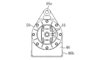
図1乃至図4に示すように、連結ピン脱着用治具40は、シリンダ連結ピン23を軸方向に移動させる油圧シリンダ41を備えている。この油圧シリンダ41のチューブ41aの先端は、円筒状の筒状部材42の基端側に結合された状態で支持されている。この筒状部材42の内部に油圧シリンダ41のロッド41bが行き来するように構成されている。筒状部材42の先端には、環状の当接部42aが形成されている。この当接部42aがシリンダ支持部22のアタッチ側ピン挿入孔22a周縁に当接可能となっている。
As shown in FIGS. 1 to 4, the connecting pin attaching / detaching
上記筒状部材42の当接部42aよりも基端側には、引張反力受部材43が取り付けられている。この引張反力受部材43は、筒状部材42の外周よりも若干大きい内径を有し、フランジが形成された一対の半円弧状断面の部材を備えている。これらの部材を筒状部材42の外周に嵌めた状態でボルト43aで締め付けることで、引張反力受部材43は、筒状部材42の先端外周に回転可能に取り付けられ、また、その前面が当接部42a後面に当接することで、抜け止めされると共に、引張反力を支持可能となっている。
A tensile reaction
一方、図5に示すように、上記シリンダ支持部22におけるアタッチ側ピン挿入孔22aの近傍には、被係止部としてのアイボルト44が取り付け可能となっている。すなわち、アタッチ側ピン挿入孔22aの周縁には、ネジ穴60aを有する一対のタップドブロック60が溶接され、このタップドブロック60にアイボルト44が取付可能となっている。タップドブロック60は、シリンダ支持部22におけるシリンダ連結ピン23の鍔部23aと反対側に設けられている。
On the other hand, as shown in FIG. 5, an
図1及び図2に示すように、上記引張反力受部材43には、係止部材45としての一対のチェーン45aの基端側が回転可能に連結されている。各チェーン45aの先端には、鉤状のフック45bが連結されている。このフック45bがアイボルト44に係止されるようになっている。
As shown in FIG.1 and FIG.2, the base end side of a pair of
図3及び図4に示すように、筒状部材42の中間部と基端には、フランジ部46が形成されている。このフランジ部46の上端には、連結ピン脱着用治具40全体を吊り上げるための吊り環46aが形成されている。フランジ部46の下端には、折り曲げられた板状の脚部46bが形成され、地面に載置したときに、連結ピン脱着用治具40全体を支持するようになっている。このように、地面に置いたときに脚部46bにより安定するので、運搬が容易である。
As shown in FIGS. 3 and 4,
上記筒状部材42の中間部の上側には、油圧シリンダ41を制御するレバー47及びコントロールバルブ48を備えたコントロールユニット55が設けられている。コントロールユニット55は、ケース56を備え、その内部に上記レバー47及びコントロールバルブ48が内蔵されている。コントロールバルブ48から油圧シリンダ41に配管49が接続され、さらに、油圧ショベル1の油圧ポンプ(図示せず)から配管49が接続可能となっている。このことで、油圧シリンダ41の操作がすぐ近くで行え、また、油圧シリンダ41への配管が容易であると共に、連結ピン脱着用治具40の運搬が容易となっている。さらに、油圧源を油圧ショベル1とすれば、油圧源を新たに用意する必要がない。
A
図1及び図2に示すように、筒状部材42の後側のフランジ部46には、筒状部材42と同径のシリンダ保護パイプ50が連結されている。このシリンダ保護パイプ50の後端に油圧シリンダ41のチューブ41aの中間部を固定することで、筒状部材42の基端から突出する油圧シリンダが保護されている。シリンダ保護パイプ50の後端には、上記フランジ部46と同様に脚部46bを有する後端フランジ50aを備えている。
As shown in FIGS. 1 and 2, a
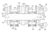
図4に示すように、油圧シリンダ41のロッド41bの先端には、連結部材51が連結されている。この連結部材51は、ロッド41bに対してその軸方向を中心に回転可能に連結されている。連結部材51は、筒状部材42の内面を摺動し、ロッド41bが安定して筒状部材42内を行き来するようになっている。連結部材51の先端には、連結孔51aが形成され、この連結孔51aにシリンダ連結ピン23よりも若干外径の小さい案内パイプ52が連結可能に構成されている。なお、案内パイプ52は、連結ピンの外径に合わせて複数用意され、いずれも連結部材51に連結可能となっている。
As shown in FIG. 4, a connecting
図7乃至図13に示すように、上記案内パイプ52は、先端及び後端が円板52aで塞がれ、両円板52aに棒状部材52bが挿入されて固定されている。この棒状部材52bの先端ネジ部には、先端に向かって細くなるアダプタ53が着脱可能に設けられている。棒状部材52bの先端は、アダプタ53を外した状態で、シリンダ連結ピン23の基端側のパイプ連結用ネジ穴23bに締結可能となっている。棒状部材52bの後端には、パイプ用アイボルト52cが締結されている。このパイプ用アイボルト52cと連結部材51の連結孔51aとにパイプ連結ピン54を挿入することで、ロッド41bの先端にピン孔に適応させた案内パイプ52が連結可能となっている。連結部材51は、このパイプ連結ピン54を中心に案内パイプ52に対して揺動可能に連結されている。このため、シリンダ連結ピン23と連結ピン脱着用治具40の軸心とが完全に一直線上に位置していなくても、案内パイプ52と連結部材51とが連結可能であり、作業が容易となる。このように、連結部材51は、案内パイプ52(シリンダ連結ピン23)に対して2つの自由度を持っている。
As shown in FIGS. 7 to 13, the
−連結ピン脱着用治具40の使用方法−
次に、本実施形態にかかる連結ピン脱着用治具40の使用方法について説明する。
-How to use the connecting pin removal jig 40-
Next, the usage method of the connection pin removal | desorption jig |
まず、シリンダ連結ピン23を抜き出す、ピン抜き作業について図7乃至図9を用いて説明する。なお、簡略化のために、コントロールユニット55、配管49等は図示していない。
First, the pin extracting operation for extracting the
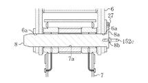
図7に示すように、回転防止部材24で挟まれたクレビス20をシリンダ支持部22に挿入した状態で、シリンダ側ピン挿入孔21aとアタッチ側ピン挿入孔22aとにシリンダ連結ピン23が挿入されている。
As shown in FIG. 7, the
まず、コントロールバルブ48に、油圧ショベル1の油圧ポンプ(図示せず)からの配管49を接続しておく。
First, a
次いで、タップドブロック60にアイボルト44を締結する。このように、シリンダ連結ピン23の抜き挿し時にのみアイボルト44を締結すればよいので、通常作業時等にアイボルト44が邪魔になることはなく、また、シリンダ支持部22側にネジ穴60a又はネジ穴60aを有するタップドブロック60を設けるだけでアイボルト44が取り付け可能となるので、構造が簡単であり、シリンダ支持部22の質量の増加も最小限に抑えられる。
Next, the
次いで、シリンダ連結ピン23の外径よりも若干小さい案内パイプ52を用意し、シリンダ連結ピン23の先端側のパイプ連結用ネジ穴23bに対し、案内パイプ52の棒状部材52bの先端を締結する。
Next, a
次いで、連結部材51を軸方向を中心に回転させ、パイプ用アイボルト52cに対して位置合わせする。このように、連結部材51がロッド41bに対して自由に回転するので、連結作業が容易である。
Next, the connecting
次いで、案内パイプ52をパイプ連結ピン54でロッド41bの先端の連結部材51に連結する。このように、案内パイプ52は、ロッド41b先端に対して取り替え可能であるので、アタッチ側ピン挿入孔22aに対応させて案内パイプ52が取り替えられる。そうすることで、案内パイプ52のみをシリンダ連結ピン23の外径に合わせて複数用意しておけば、抜き挿ししようとするシリンダ連結ピン23よりも若干外径が小さいものを選択することができる。また、案内パイプ52の外径をアタッチ側ピン挿入孔22aに対して多少の余裕を持たせることで、アタッチ側ピン挿入孔22aが多少ずれていても、案内パイプ52の抜き挿しが容易である。
Next, the
このとき、筒状部材42を吊り上げた状態で、引張反力受部材43のみが回転するので、引張反力受部材43のみを回転させて係止部材45とアイボルト44との位置合わせを行い、図8に示すように、フック45bをアイボルト44に連結する。このため、筒状部材42を吊り上げて位置決めがし易い上、油圧シリンダ41の配管が捩れない。このように、アタッチメントの連結ピンによってアイボルト44の配置が異なるが、アイボルト44に合わせて引張反力受部材43が回転可能であるので、異なる配置のアイボルト44に対しても最適な位置に係止部材45が回転され、アイボルト44に係止される。また、アイボルト44にフック45bを掛けた状態でチェーン45aを捩らせたり、撓ませたりすることができるので、異なるアイボルト44の配置に対して対応し易い。
At this time, since only the tensile reaction
次いで、鍔部23aを押さえるプレート27を取り外した後、係止部材45をアイボルト44に係止した状態で、引張反力を受けながら、レバー47を操作して油圧シリンダ41のロッド41bを伸長させる。
Next, after removing the
すると、図9に示すように、ロッド41b先端に連結された案内パイプ52によってシリンダ連結ピン23がアタッチ側ピン挿入孔22aから押し出される。このため、ロッド41bがアタッチ側ピン挿入孔22a内に入り込まず、シリンダ側ピン挿入孔21aとアタッチ側ピン挿入孔22aとがずれようとしても、油圧シリンダ41が損傷することはない。また、推力の大きいロッド41bの伸長時にシリンダ連結ピン23が押し出されるので、より大きな力を要するシリンダ連結ピン23の抜き出しが容易に行われる。
Then, as shown in FIG. 9, the
最後に、シリンダ連結ピン23を案内パイプ52から取り外し、さらに、筒状部材42の当接部42aをアタッチ側ピン挿入孔22aの周縁に当接させながら、油圧シリンダ41を短縮させて案内パイプ52を抜き出す。このことで、シリンダ連結ピン23の抜き出し作業が終了する。
Finally, the
次いで、図10乃至図13を用いて、シリンダ連結ピン23を挿入する、ピン挿し作業について説明する。
Next, a pin insertion operation for inserting the
まず、図10に示すように、先端にアダプタ53を締結した案内パイプ52をパイプ連結ピン54でロッド41b先端に連結し、油圧シリンダ41のロッド41bを短縮させて筒状部材42内に引き込んでおく。
First, as shown in FIG. 10, a
次いで、上記ピン抜き作業と同様に、フック45bをアイボルト44に係止する。そして、図11に示すように、レバー47を操作してロッド41bを伸ばし、案内パイプ52をアタッチ側ピン挿入孔22a及びシリンダ側ピン挿入孔21aに挿入する。このとき、アダプタ53によって案内パイプ52がアタッチ側ピン挿入孔22a及びシリンダ側ピン挿入孔21aに誘導されるので、2本のアームシリンダ9を連結するような場合であっても、案内パイプ52の挿入が容易に行われる。
Next, the
次いで、案内パイプ52の先端から、アダプタ53を取り外し、図12に示すように、シリンダ連結ピン23を替わりに締結し、フック45bをアイボルト44から外し、アイボルト44を取り外す。
Next, the
次いで、筒状部材42の当接部42aをアタッチ側ピン挿入孔22a周縁に当接させた状態で、圧縮反力を受けながら、油圧シリンダ41のロッド41bを短縮させてシリンダ連結ピン23を引き込む。このことで、図13に示すように、シリンダ連結ピン23がアタッチ側ピン挿入孔22a及びシリンダ側ピン挿入孔21aに挿入される。このとき、筒状部材42の内部にまで必ずしもシリンダ連結ピン23を引き込む必要はないが、案内パイプ52が筒状部材42に入り込む場合であっても、筒状部材42の内径を最大外径の案内パイプ52よりも大きくすれば、1つの筒状部材42で全ての連結ピンの抜き挿しが行える。
Next, the
次いで、鍔部23aをシリンダ支持部22にプレート27によって押さえた状態で締結する。
Next, the
最後に案内パイプ52をシリンダ連結ピン23から取り外すことによって、ピン挿し作業が終了する。
Finally, by removing the
このように、鍔部23aを有するシリンダ連結ピン23であっても、その先端側から抜き挿しを行うことから、シリンダ連結ピン23の鍔部23aが油圧シリンダ41を支持する筒状部材42の内部を通過しないので、筒状部材42を鍔部23aに合わせて大きくしたり、切欠を設けたりする必要がない。
In this way, even the
−実施形態1の効果−
したがって、本実施形態にかかる連結ピン脱着用治具40によると、引張反力受部材43をアイボルト44に対して筒状部材の軸方向を中心に回転可能に構成したことにより、アイボルト44に対して最適な位置に係止部材45を回転させ、油圧シリンダ41の推力に対する引張反力を受けることができる。このため、1つの連結ピン脱着用治具40で異なる外径のシリンダ連結ピン23の脱着を行うことができる。
-Effect of Embodiment 1-
Therefore, according to the connecting
上記実施形態によれば、油圧シリンダ41のロッド41bの先端に少なくともロッド41bの軸方向を中心に回転可能な連結部材51を設け、この連結部材51に案内パイプ52を連結するようにしたことにより、連結部材51がロッド41bに対して固定されたものに比べて連結部材51を極めて容易に案内パイプ52に連結することができる。
According to the above-described embodiment, the connecting
上記実施形態によれば、基端側に鍔部23aを有するシリンダ連結ピン23の先端側からシリンダ連結ピン23の抜き挿しを行うようにしたことにより、筒状部材42の形状の制約が小さくなり、1つの筒状部材42のみで異なる外径のシリンダ連結ピン23の脱着作業を行うことができる。また、推力の大きいロッド41bの伸長時にシリンダ連結ピン23を押し出すことができるので、シリンダ連結ピン23の脱着を容易に行うことができる。
According to the above embodiment, since the
上記実施形態によれば、引張反力受部材43を筒状部材42の先端外周に回転可能に取り付けたことにより、筒状部材42を吊った状態で、油圧シリンダ41の配管49が捩れることはないので、係止部材45とアイボルト44との位置合わせを容易に行うことができる。
According to the above-described embodiment, the tensile reaction
上記実施形態によれば、油圧シリンダ41のロッド41bの先端にシリンダ連結ピン23よりも若干外径の小さい案内パイプ52を連結可能としたことにより、油圧シリンダ41の損傷を防ぎながら外径の異なるシリンダ連結ピン23であっても、極めて容易に脱着を行うことができる。
According to the above embodiment, the
上記実施形態によれば、案内パイプ52の先端にアダプタ53を取り付けたことにより、案内パイプ52を容易にアタッチ側ピン挿入孔22a及びシリンダ側ピン挿入孔21aに誘導することができるので、さらに容易にシリンダ連結ピン23の脱着を行うことができる。
According to the above embodiment, the
上記実施形態によれば、シリンダ支持部22に締結したアイボルト44を係止部材45に係止するようにしたことにより、被係止部を取り付け取り外しが容易な簡単な構造とすることができ、アタッチメント等の設計変更を最小限とすることができる。
According to the above embodiment, the
上記実施形態によれば、係止部材45を可撓性のあるチェーン45a及びその先端に連結されたフック45bよりなるものとしたことにより、異なる配置のアイボルト44にも柔軟に対応することができるので、異なる外径のシリンダ連結ピン23の脱着をさらに効率よく行うことができる。
According to the above embodiment, since the locking
上記実施形態によれば、筒状部材42に油圧シリンダ41を制御するコントロールユニット55を設けたことにより、配管、操作及び運搬が容易な連結ピン脱着用治具40が得られる。
According to the above embodiment, by providing the
上記実施形態によれば、筒状部材42に吊り環46aと脚部46bとを設けたことにより、扱い易い連結ピン脱着用治具40が得られる。
According to the above-described embodiment, by providing the
(実施形態2)
図14乃至図16は本発明の実施形態2の連結ピン脱着用治具140を示す。主に連結ピンの鍔部側から連結ピンを抜き差しする点で上記実施形態1と異なる。なお、以下の各実施形態では、図1乃至図13と同じ部分については同じ符号を付してその詳細な説明は省略する。
(Embodiment 2)
14 to 16 show a connecting pin attaching / detaching
すなわち、上記実施形態1では、引張反力受部材43単体を回転可能としたが、本実施形態では、図16に示すように、筒状部材142ごと回転可能としている。筒状部材142は、フランジ部146(吊り環146a)に対して回動可能に構成されている。
That is, in Embodiment 1 described above, the tensile reaction
本実施形態では、図17及び図18に示すように、アーム7の後端とフロントブーム6とを連結するアーム連結ピン8について説明する。アーム連結ピン8は、第1連結体としてのフロントブーム6のアーム連結ピン挿入孔6a(ピン孔)及び第2連結体としてのアーム7のアーム側挿入孔7aに挿通されている。アーム連結ピン挿入孔6aの近傍には、アイボルト44を締結するためのネジ穴60aが設けられている。アーム連結ピン8は、基端側に鍔部8aを有し、その中心にピン連結用ネジ穴8bを備えている。
In this embodiment, as shown in FIGS. 17 and 18, an
上記実施形態1と同様に、連結部材51は、ロッド41bに対してその軸方向を中心に回転可能に連結されている。図19に示すように、ロッド41bの先端の連結部材51には、ピン連結用ネジ穴8bに締結したピン連結用アイボルト152cが直接連結されるようになっている。連結部材51は、このピン連結ピン154を中心にアーム連結ピン8に対して揺動可能に連結されている。このため、アーム連結ピン8と連結ピン脱着用治具140の軸心とが完全に一直線上に位置していなくても、両者が連結可能であり、作業が容易となる。このように、連結部材51は、アーム連結ピン8に対して2つの自由度を持っている。
As in the first embodiment, the connecting
本実施形態の引張反力受部材143は、筒状部材142の先端に溶接されている。係止部材145は、基端側がこの引張反力受部材143に回動可能に連結され、先端側がアイボルト44に連結可能な板状部材よりなる。
The tensile reaction
筒状部材142の先端には、当接部142aが形成され、その上側は、基端側に向けて開口142bが形成されている。このことで、アーム連結ピン8の鍔部8aが筒状部材142内を通過可能となっている。
A
本実施形態の連結ピン脱着用治具140の使用方法について、簡単に説明すると、上記実施形態1と異なり、案内パイプ52を使用せずに、直接アーム連結ピン8を抜き挿しする。
The use method of the connecting
すなわち、アーム連結ピン8を差し込む場合には、図15に示すように、アーム連結ピン8を筒状部材142内に納めた状態で、アーム連結ピン挿入孔6aに近付け、図16に示すように、筒状部材142をその軸方向を中心に回転させて係止部材145をアイボルト44に対して位置決めして連結し、図19に示すように、係止部材145で引張何力を受けながらアーム連結ピン8をアーム連結ピン挿入孔6aに差し込む。次いで、ピン連結ピン154を抜いた後、鍔部8aを固定し、ピン連結用アイボルト152cを抜く。
That is, when inserting the
反対に、アーム連結ピン8を引き抜く場合には、ピン連結用アイボルト152cをアーム連結ピン8のピン連結用ネジ穴8bに締結し、連結部材51を近付けながら、その軸方向を中心に回転させ、ピン連結ピン154でピン連結用アイボルト152cに連結する。そして、筒状部材142の当接部142aをアーム連結ピン挿入孔6aの周縁に当接させながら、ロッド41bを縮めて図15に示すように、アーム連結ピン8を筒状部材142内に引き込んで、アーム連結ピン8を抜き出す。このとき、アーム連結ピン8を軸方向に回転させて鍔部8aを開口142bに位置合わせすれば、鍔部8aは筒状部材142に衝突しない。
On the other hand, when pulling out the
したがって、本実施形態にかかる連結ピン脱着用治具40によっても、筒状部材142全体を回転させて係止部材145をアイボルト44に位置決めできるようにしたことにより、アイボルト44に対して最適な位置に係止部材45を回転させ、油圧シリンダ41の推力に対する引張反力を受けることができるので、1つの連結ピン脱着用治具140で異なる外径の連結ピンの脱着を行うことができる。
Therefore, the connecting
上記実施形態によれば、油圧シリンダ41のロッド41bの先端に少なくともロッド41bの軸方向を中心に回転可能な連結部材51を設け、この連結部材51にアーム連結ピン8を連結するようにしたことにより、連結部材51がロッド41bに対して固定されたものに比べて連結部材51を極めて容易にアーム連結ピン8に連結することができる。
According to the above-described embodiment, the connecting
なお、係止部材145は、板状部材で構成したが、上記実施形態1と同様にチェーン45a及びフック45bからなるものとしてもよい。
In addition, although the locking
(その他の実施形態)
本発明は、上記実施形態について、以下のような構成としてもよい。
(Other embodiments)
The present invention may be configured as follows with respect to the above embodiment.
すなわち、係止部材45,145をアイボルト44ではなく、直接第1連結体に係止させてもよい。
That is, the locking
また、上述したように、連結ピンは、シリンダ連結ピン23やアーム連結ピン8に限定されず、アタッチメント同士又はアタッチメントとそのアタッチメントを駆動する油圧シリンダとを連結する連結ピン等に本発明を適用することができる。
Further, as described above, the connecting pin is not limited to the
また、上記実施形態では、建設機械として油圧ショベルの例を示したが、クレーンや、土木機械であってもよい。 Moreover, in the said embodiment, although the example of the hydraulic shovel was shown as a construction machine, a crane and a civil engineering machine may be used.
なお、以上の実施形態は、本質的に好ましい例示であって、本発明、その適用物や用途の範囲を制限することを意図するものではない。 In addition, the above embodiment is an essentially preferable illustration, Comprising: It does not intend restrict | limiting the range of this invention, its application thing, or a use.
1 油圧ショベル(建設機械)
6 フロントブーム(第1連結体)
7 アーム(第2連結体)
8 アーム連結ピン(連結ピン)
8a 鍔部
9 アームシリンダ(第2連結体)
9a ピストンロッド
21a シリンダ側ピン挿入孔(ピン孔)
22 シリンダ支持部(第1連結体)
22a アタッチ側ピン挿入孔(ピン孔)
23 シリンダ連結ピン(連結ピン)
23a 鍔部
40 連結ピン脱着用治具
41 油圧シリンダ
42 筒状部材
42a 当接部
43 引張反力受部材
44 アイボルト
45 係止部材
45a チェーン
45b フック
46a 吊り環
46b 脚部
47 レバー
48 コントロールバルブ
51 連結部材
52 案内パイプ
53 アダプタ
55 コントロールユニット
60 タップドブロック
60a ネジ穴
140 連結ピン脱着用治具
142 筒状部材
142a 当接部
143 引張反力受部材
145 係止部材
146a 吊り環
1 Excavator (construction machine)
6 Front boom (first connected body)
7 Arm (second connected body)
8 Arm connection pin (connection pin)
22 Cylinder support (first connected body)
22a Attached side pin insertion hole (pin hole)
23 Cylinder connection pin (connection pin)
Claims (10)
上記連結ピンを軸方向に移動させる油圧シリンダと、
上記油圧シリンダのチューブが基端側に支持されると共に、内部に該油圧シリンダのロッドが行き来し、先端が第1連結体のピン孔周縁に当接可能な筒状部材と、
上記筒状部材の先端側に取り付けられ、該筒状部材にかかる引張反力を受ける引張反力受部材と、
基端側が上記引張反力受部材に連結され、先端側が上記第1連結体に係止される係止部材とを備え、
少なくとも上記引張反力受部材が上記第1連結体に対して上記筒状部材の軸方向を中心に回転可能に構成されている
ことを特徴とする連結ピン脱着用治具。 A connection pin detachment jig that is inserted into a pin hole provided in each of the first connection body and the second connection body of the construction machine and inserts and removes a connection pin that connects the first and second connection bodies,
A hydraulic cylinder for moving the connecting pin in the axial direction;
A tubular member in which the tube of the hydraulic cylinder is supported on the base end side, and the rod of the hydraulic cylinder goes back and forth inside, and the tip can be brought into contact with the peripheral edge of the pin hole of the first connecting body;
A tensile reaction force receiving member attached to the distal end side of the cylindrical member and receiving a tensile reaction force applied to the cylindrical member;
A proximal end side is coupled to the tensile reaction force receiving member, and a distal end side is latched to the first coupling body;
A connecting pin attaching / detaching jig, wherein at least the tensile reaction force receiving member is configured to be rotatable about the axial direction of the cylindrical member with respect to the first connecting body.
上記油圧シリンダのロッドの先端には、少なくとも該ロッドの軸方向を中心に回転可能な連結部材が設けられている
ことを特徴とする連結ピン脱着用治具。 In the connecting pin detaching jig according to claim 1,
A connecting pin attaching / detaching jig characterized in that a connecting member capable of rotating at least about the axial direction of the rod is provided at the tip of the rod of the hydraulic cylinder.
上記連結ピンの基端側には、鍔部が形成され、
上記係止部材は、上記第1連結体における上記連結ピンの鍔部と反対側に係止される
ことを特徴とする連結ピン脱着用治具。 In the connection pin detachment jig according to claim 1 or 2,
On the base end side of the connecting pin, a collar is formed,
The engagement pin detachment jig, wherein the engagement member is engaged with a side opposite to the flange portion of the connection pin in the first connection body.
上記引張反力受部材は、上記筒状部材の先端外周に該筒状部材の軸方向に回転可能に取り付けられている
ことを特徴とする連結ピン脱着用治具。 In the connecting pin detaching jig according to any one of claims 1 to 3,
The connecting pin attaching / detaching jig, wherein the tensile reaction force receiving member is attached to an outer periphery of a distal end of the cylindrical member so as to be rotatable in an axial direction of the cylindrical member.
上記油圧シリンダのロッドの先端側には、上記連結ピンよりも若干外径の小さい案内パイプが連結可能に構成されている
ことを特徴とする連結ピン脱着用治具。 In the connection pin removal jig according to any one of claims 1 to 4,
A connecting pin attaching / detaching jig, wherein a guide pipe having a slightly smaller outer diameter than the connecting pin is connectable to a tip end side of the rod of the hydraulic cylinder.
上記案内パイプの先端には、先端に向かって細くなるアダプタが取り付けられている
ことを特徴とする連結ピン脱着用治具。 In the connection pin removal jig according to claim 4 or 5,
An adapter for attaching and detaching a connecting pin, wherein an adapter that narrows toward the tip is attached to the tip of the guide pipe.
上記係止部材は、上記第1連結体に締結したアイボルトに係止される
ことを特徴とする連結ピン脱着用治具。 In the connecting pin detaching jig according to any one of claims 1 to 6,
The connecting pin attaching / detaching jig, wherein the locking member is locked to an eyebolt fastened to the first connecting body.
上記係止部材は、チェーン及びその先端に連結されたフックよりなる
ことを特徴とする連結ピン脱着用治具。 In the connection pin detachment jig according to any one of claims 1 to 7,
The engagement pin detachment jig is characterized in that the locking member comprises a chain and a hook connected to the tip of the chain.
上記筒状部材には、上記油圧シリンダを制御するレバー及びコントロールバルブを備えたコントロールユニットが設けられている
ことを特徴とする連結ピン脱着用治具。 In the connection pin removal jig according to any one of claims 1 to 8,
A connecting pin attaching / detaching jig, wherein the cylindrical member is provided with a control unit including a lever and a control valve for controlling the hydraulic cylinder.
上記筒状部材は、
吊り上げ用の吊り環と、
地面に載置するための脚部と
を備えている
ことを特徴とする連結ピン脱着用治具。 In the connection pin detachment jig according to any one of claims 1 to 9,
The cylindrical member is
A lifting ring for lifting;
A connecting pin detaching jig comprising a leg for placing on the ground.
Priority Applications (1)
| Application Number | Priority Date | Filing Date | Title |
|---|---|---|---|
| JP2007179280A JP2009013730A (en) | 2007-07-09 | 2007-07-09 | Connection pin attaching/detaching jig |
Applications Claiming Priority (1)
| Application Number | Priority Date | Filing Date | Title |
|---|---|---|---|
| JP2007179280A JP2009013730A (en) | 2007-07-09 | 2007-07-09 | Connection pin attaching/detaching jig |
Publications (1)
| Publication Number | Publication Date |
|---|---|
| JP2009013730A true JP2009013730A (en) | 2009-01-22 |
Family
ID=40354952
Family Applications (1)
| Application Number | Title | Priority Date | Filing Date |
|---|---|---|---|
| JP2007179280A Pending JP2009013730A (en) | 2007-07-09 | 2007-07-09 | Connection pin attaching/detaching jig |
Country Status (1)
| Country | Link |
|---|---|
| JP (1) | JP2009013730A (en) |
Cited By (3)
| Publication number | Priority date | Publication date | Assignee | Title |
|---|---|---|---|---|
| KR100997013B1 (en) | 2009-02-17 | 2010-11-25 | 주식회사 우도산기 | Conveyor Chain Link Pin Shaft Prevention Device |
| DE102017113099A1 (en) | 2016-06-17 | 2017-12-21 | Kobelco Construction Machinery Co., Ltd. | CLUTCH BOLT TAKING DEVICE AND WORK MACHINE THUS PROVIDED |
| CN110253267A (en) * | 2019-07-23 | 2019-09-20 | 山东科技大学 | It is a kind of large size pin shaft detaching equipment and its application |
-
2007
- 2007-07-09 JP JP2007179280A patent/JP2009013730A/en active Pending
Cited By (6)
| Publication number | Priority date | Publication date | Assignee | Title |
|---|---|---|---|---|
| KR100997013B1 (en) | 2009-02-17 | 2010-11-25 | 주식회사 우도산기 | Conveyor Chain Link Pin Shaft Prevention Device |
| DE102017113099A1 (en) | 2016-06-17 | 2017-12-21 | Kobelco Construction Machinery Co., Ltd. | CLUTCH BOLT TAKING DEVICE AND WORK MACHINE THUS PROVIDED |
| US10323380B2 (en) | 2016-06-17 | 2019-06-18 | Kobelco Construction Machinery Co., Ltd. | Coupling pin extracting apparatus and working machine provided with same |
| DE102017113099B4 (en) | 2016-06-17 | 2023-12-07 | Kobelco Construction Machinery Co., Ltd. | CLUTCH PIN REMOVAL DEVICE AND WORK MACHINE EQUIPPED THEREOF |
| CN110253267A (en) * | 2019-07-23 | 2019-09-20 | 山东科技大学 | It is a kind of large size pin shaft detaching equipment and its application |
| CN110253267B (en) * | 2019-07-23 | 2024-03-22 | 山东科技大学 | Dismounting device for large pin shaft and application thereof |
Similar Documents
| Publication | Publication Date | Title |
|---|---|---|
| EP2230435A1 (en) | Extendable fluid coupler | |
| JP5513820B2 (en) | Trunnion transport system and crane using the same | |
| JP2008303642A (en) | Existing pile removing device and removing method | |
| JP5004978B2 (en) | Detachment device between front components of construction machinery | |
| JP2009013730A (en) | Connection pin attaching/detaching jig | |
| US20170030048A1 (en) | Excavator Attachments Alignment Tool | |
| JP4244765B2 (en) | Work machine and its assembly / disassembly method | |
| KR200456465Y1 (en) | tongs for excavator | |
| JP2013108247A (en) | Apparatus for connecting/disconnecting upper and lower connecting pins of work machine and method for assembling/disassembling the work machine | |
| JP4492077B2 (en) | Work machine boom and its assembly / disassembly method | |
| JP4028438B2 (en) | Pin insertion / extraction method and pin insertion / extraction jig used therefor | |
| JP3956211B2 (en) | Transportation method of demolition machine and its proximal boom | |
| JP2000211888A (en) | Coupling pin mounting/removing device of construction machine | |
| JP2005133507A (en) | Work machine attaching/detaching device by means of pin | |
| CN102019550B (en) | A heavy-duty pin shaft opening device | |
| KR101870713B1 (en) | Conneting structure of quick coupler for construction machine | |
| KR101200359B1 (en) | Attachment With Interchageable Jaw | |
| JP7005059B1 (en) | How to attach / detach the cylinder cover in the crusher and the crusher | |
| JP4117882B2 (en) | Stabilizer for shaft digging bucket | |
| JP2006097348A (en) | Work tool installing device | |
| JP4535092B2 (en) | Construction machinery | |
| JP2007211583A (en) | Detachable device for connecting pin | |
| JP2002201887A (en) | Excavator | |
| JP2010159801A (en) | Two-member connecting device | |
| JP3881227B2 (en) | Connecting machine for connecting and disconnecting construction machines |