EP1978653B1 - Optical wavelength multiplexing access system - Google Patents
Optical wavelength multiplexing access system Download PDFInfo
- Publication number
- EP1978653B1 EP1978653B1 EP07707514.1A EP07707514A EP1978653B1 EP 1978653 B1 EP1978653 B1 EP 1978653B1 EP 07707514 A EP07707514 A EP 07707514A EP 1978653 B1 EP1978653 B1 EP 1978653B1
- Authority
- EP
- European Patent Office
- Prior art keywords
- optical
- wavelength
- wavelengths
- downstream
- selectable
- Prior art date
- Legal status (The legal status is an assumption and is not a legal conclusion. Google has not performed a legal analysis and makes no representation as to the accuracy of the status listed.)
- Active
Links
Images


Classifications
-
- H—ELECTRICITY
- H04—ELECTRIC COMMUNICATION TECHNIQUE
- H04B—TRANSMISSION
- H04B10/00—Transmission systems employing electromagnetic waves other than radio-waves, e.g. infrared, visible or ultraviolet light, or employing corpuscular radiation, e.g. quantum communication
- H04B10/40—Transceivers
-
- H—ELECTRICITY
- H04—ELECTRIC COMMUNICATION TECHNIQUE
- H04J—MULTIPLEX COMMUNICATION
- H04J14/00—Optical multiplex systems
- H04J14/02—Wavelength-division multiplex systems
- H04J14/0227—Operation, administration, maintenance or provisioning [OAMP] of WDM networks, e.g. media access, routing or wavelength allocation
-
- H—ELECTRICITY
- H04—ELECTRIC COMMUNICATION TECHNIQUE
- H04B—TRANSMISSION
- H04B10/00—Transmission systems employing electromagnetic waves other than radio-waves, e.g. infrared, visible or ultraviolet light, or employing corpuscular radiation, e.g. quantum communication
- H04B10/07—Arrangements for monitoring or testing transmission systems; Arrangements for fault measurement of transmission systems
- H04B10/075—Arrangements for monitoring or testing transmission systems; Arrangements for fault measurement of transmission systems using an in-service signal
- H04B10/079—Arrangements for monitoring or testing transmission systems; Arrangements for fault measurement of transmission systems using an in-service signal using measurements of the data signal
- H04B10/0793—Network aspects, e.g. central monitoring of transmission parameters
-
- H—ELECTRICITY
- H04—ELECTRIC COMMUNICATION TECHNIQUE
- H04B—TRANSMISSION
- H04B10/00—Transmission systems employing electromagnetic waves other than radio-waves, e.g. infrared, visible or ultraviolet light, or employing corpuscular radiation, e.g. quantum communication
- H04B10/07—Arrangements for monitoring or testing transmission systems; Arrangements for fault measurement of transmission systems
- H04B10/075—Arrangements for monitoring or testing transmission systems; Arrangements for fault measurement of transmission systems using an in-service signal
- H04B10/079—Arrangements for monitoring or testing transmission systems; Arrangements for fault measurement of transmission systems using an in-service signal using measurements of the data signal
- H04B10/0795—Performance monitoring; Measurement of transmission parameters
- H04B10/07957—Monitoring or measuring wavelength
-
- H—ELECTRICITY
- H04—ELECTRIC COMMUNICATION TECHNIQUE
- H04B—TRANSMISSION
- H04B10/00—Transmission systems employing electromagnetic waves other than radio-waves, e.g. infrared, visible or ultraviolet light, or employing corpuscular radiation, e.g. quantum communication
- H04B10/25—Arrangements specific to fibre transmission
- H04B10/2581—Multimode transmission
-
- H—ELECTRICITY
- H04—ELECTRIC COMMUNICATION TECHNIQUE
- H04B—TRANSMISSION
- H04B10/00—Transmission systems employing electromagnetic waves other than radio-waves, e.g. infrared, visible or ultraviolet light, or employing corpuscular radiation, e.g. quantum communication
- H04B10/27—Arrangements for networking
- H04B10/272—Star-type networks or tree-type networks
-
- H—ELECTRICITY
- H04—ELECTRIC COMMUNICATION TECHNIQUE
- H04J—MULTIPLEX COMMUNICATION
- H04J14/00—Optical multiplex systems
- H04J14/02—Wavelength-division multiplex systems
- H04J14/0227—Operation, administration, maintenance or provisioning [OAMP] of WDM networks, e.g. media access, routing or wavelength allocation
- H04J14/0241—Wavelength allocation for communications one-to-one, e.g. unicasting wavelengths
- H04J14/0242—Wavelength allocation for communications one-to-one, e.g. unicasting wavelengths in WDM-PON
- H04J14/0245—Wavelength allocation for communications one-to-one, e.g. unicasting wavelengths in WDM-PON for downstream transmission, e.g. optical line terminal [OLT] to ONU
- H04J14/0246—Wavelength allocation for communications one-to-one, e.g. unicasting wavelengths in WDM-PON for downstream transmission, e.g. optical line terminal [OLT] to ONU using one wavelength per ONU
-
- H—ELECTRICITY
- H04—ELECTRIC COMMUNICATION TECHNIQUE
- H04J—MULTIPLEX COMMUNICATION
- H04J14/00—Optical multiplex systems
- H04J14/02—Wavelength-division multiplex systems
- H04J14/0227—Operation, administration, maintenance or provisioning [OAMP] of WDM networks, e.g. media access, routing or wavelength allocation
- H04J14/0241—Wavelength allocation for communications one-to-one, e.g. unicasting wavelengths
- H04J14/0242—Wavelength allocation for communications one-to-one, e.g. unicasting wavelengths in WDM-PON
- H04J14/0249—Wavelength allocation for communications one-to-one, e.g. unicasting wavelengths in WDM-PON for upstream transmission, e.g. ONU-to-OLT or ONU-to-ONU
- H04J14/025—Wavelength allocation for communications one-to-one, e.g. unicasting wavelengths in WDM-PON for upstream transmission, e.g. ONU-to-OLT or ONU-to-ONU using one wavelength per ONU, e.g. for transmissions from-ONU-to-OLT or from-ONU-to-ONU
-
- H—ELECTRICITY
- H04—ELECTRIC COMMUNICATION TECHNIQUE
- H04J—MULTIPLEX COMMUNICATION
- H04J14/00—Optical multiplex systems
- H04J14/02—Wavelength-division multiplex systems
- H04J14/0278—WDM optical network architectures
- H04J14/0282—WDM tree architectures
-
- H—ELECTRICITY
- H04—ELECTRIC COMMUNICATION TECHNIQUE
- H04J—MULTIPLEX COMMUNICATION
- H04J14/00—Optical multiplex systems
- H04J14/02—Wavelength-division multiplex systems
- H04J14/0226—Fixed carrier allocation, e.g. according to service
Definitions
- the present invention relates to an optical transmitter (TX) and receiver (RX) device used for wavelength multiplexed optical communication and a star-type network using the device.
- TX optical transmitter
- RX receiver
- monitoring light with a different wavelength from signal light is used to transmit wavelength information of the signal light and the like as monitoring information for monitor and control of wavelengths to be used (Patent Document 1).
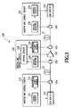
- Fig. 1 shows an exemplary configuration for monitor and control in such relay network.
- network 100 wavelength-multiplexed signal light is transmitted from WDM device A 110 to WDM device B 130 via linear optical repeater 120.
- monitoring information such as power, wavelengths in use, and the number of the wavelengths for signal light is transmitted from monitor and control circuit 112 to monitor and control circuit 132 via monitor and control circuit 122 using monitoring light with a different wavelength from the signal light.
- the monitoring information of the signal light after provided with more channels is conveyed from control circuit 114 at the transmitting side through monitoring light source 116. This monitoring light is multiplexed with the signal light at multiplexer 20a, and transmitted out to optical fiber 10.
- Monitor and control circuit 122 receives the monitoring light transmitted via optical fiber 10 at optical receiver 128 and obtains the monitoring information. At the same time, monitor and control circuit 122 monitors the total light power of the signal light at the output of linear optical repeater 120, and computes the average power per channel based on the number of in-use wavelengths of the signal light obtained from the monitoring information. Monitoring control circuit 122 controls the output power of linear optical repeater 120 so that the average power becomes a desired value. Accordingly, after provided with more channels, the light power on each channel can be kept constant at linear optical repeater 120.
- monitoring information is transmitted to monitor and control circuit 132 through monitoring light source 126, and received by optical receiver 138. Based on the monitoring information, control circuit 134 controls the output power of an optical amplifier in WDM device B 130 so as to be a desired value. As such, the signal light is transmitted from WDM device A 110 to WDM device B 130.
- the monitoring light is used in such a configuration, optical components such as light sources 116, 126, multiplexers 20a, 20c, demultiplexers 20b, 20d, and optical receivers 128, 138 are required, which are costly.
- demultiplexers and optical receivers for monitoring light are required for each subscriber terminal.
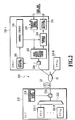
- Fig. 2 shows an exemplary configuration in which the configuration for monitor and control shown in Fig. 1 is applied to a star-type wavelength multiplexed network.
- Network 200 is composed of an optical line terminal (OLT) 210 installed at a station, an optical fiber 10 through which wavelength-multiplexed signal light and monitoring light propagate, a power splitter 30 for power-splitting the signal light and the monitoring light in the ratio of 1 to N, and N optical network units (ONUs) 230-1 to 230-N, each receiving the split signal light and the split monitoring light.
- OLT optical line terminal
- ONUs optical network units
- the monitoring information is transmitted from OLT 210 out to optical fiber 10 using monitoring light source 214.
- the monitoring light is split into N at power splitter 30, and transmitted to ONUs 230-1 to 230-N.
- Each ONU 230 receives the monitoring light with optical receiver 242, and based on in-use wavelength information transmitted as the monitoring information, tunable filter 234 and optical transmitter 238 are assigned by control circuit 244 so as to receive a predetermined channel.
- Patent Document 1 Japanese Patent Laid-Open No. 10-51057
- Document EP 0 810 752 discloses a method of controlling a wavelength of emitted light in a network system including detecting a wavelength falling within a continuous wavelength-tunable range of the light emitting means which does not interfere with any wavelengths of light being transmitted on the light transmission line, and emitting light at the detected wavelength.
- Document EP 0 438 155 discloses an optical communication equipment including a wavelength detection unit for detecting an unused first wavelength from the entire wavelength range to be commonly used.
- the present invention has been made in view of the foregoing problem, and it is an object to provide a star-type wavelength multiplexed communication network using an optical transmitter and receiver (TX/RX) device capable of assigning the wavelengths without using monitoring light.
- TX/RX optical transmitter and receiver
- an optical TX/RX device and a method according to the respective independent claims are provided. Further details are set out in the dependent claims.
- an optical TX/RX device capable of assigning the wavelengths can be provided without using monitoring light. Accordingly, the optical components relating to the transmission of the monitoring light such as a light source, a multiplexer, a demultiplexer, and an optical receiver can be eliminated. Further, the optical TX/RX device according to an aspect of the present invention is only required to monitor the signal power, and can be applied to various transmission frame formats. Still further, since the wavelengths can automatically be assigned with a simple algorithm, it is especially advantageous for network expansion with small start-ups, with which economy is critical.
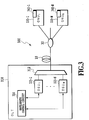
- Fig. 3 shows an exemplary configuration of a star-type network using an optical TX/RX device according to the present invention.
- Network 300 is composed of an optical line terminal (OLT) 310 for transmitting and receiving wavelength-multiplexed signal light, an optical fiber 10 through which the signal light propagates, a power splitter 30 for combining or splitting the optical signal with 1 to N, and N optical network units (ONUs) (optical TX/RX devices) 330-1 to 330-N each transmitting and receiving optical signal.
- OLT optical line terminal
- ONUs optical network units
- OLT 310 comprises N optical subscriber units (OSUs) 320-1 to 320-N each transmitting and receiving signal light with an assigned wavelength, a wavelength control circuit 314 for controlling the wavelengths of signal light used for TX and RX by the OSUs, and a wavelength multi/demultiplexer 312 for multiplexing the optical signals from the OSUs and demultiplexing the optical signals from the ONUs.
- OSUs 320-1 to 320-N are assigned with different wavelengths, respectively, by wavelength control circuit 314.
- wavelength control circuit 314 may assign these wavelengths to the OSUs in fixed or dynamic way. Alternatively, it may be configured to use an OSU with a prefixed TX and RX wavelengths and stabilize the wavelengths by the wavelength control circuit.
- An optical signal from an OSU assigned with a wavelength is wavelength-multiplexed by wavelength multi/demultiplexer 312 and then transmitted out to optical fiber 10.
- the wavelength-multiplexed signal light from OLT 310 is split into N paths of power splitter 30 via optical fiber 10, and then transmitted to ONUs 330-1 to 330-N for the subscribers on the respective paths.
- each ONU receives the optical signal with the downstream wavelength selected by wavelength control circuit 340 out of the wavelength-multiplexed signal light from the OLT.
- each ONU transmits the optical signal to the OLT using the upstream wavelength selected by wavelength control circuit 340.
- the signal light from each ONU is combined at power splitter 30, and transmitted to OLT 310 via optical fiber 10.
- the signal light from the ONUs is demultiplexed by-wavelength at wavelength multi/demultiplexer 312, and transmitted to the respective OSUs.
- Fig. 4 shows an example of wavelength allocation for upstream and downstream in such star-type network. As shown in the figure, the downstream wavelengths ⁇ d1 to ⁇ dN and the upstream wavelengths ⁇ u1 to ⁇ uN are allocated on the ITU grid. Although Fig. 4 shows an example of allocating the upstream wavelengths on the shorter wavelength side and the downstream wavelengths on the longer wavelength side, it should be noted that any arbitrary wavelength allocations may be used.
- Fig. 5 shows an exemplary configuration of the ONU according to the present invention.
- ONU 330 transmits and receives the signal light with OLT 310 over the upstream and the downstream wavelengths.
- Wavelength multi/demultiplexer 332 multiplexes and demultiplexes the upstream wavelength and the downstream wavelength.
- a desired wavelength out of the wavelength-multiplexed downstream wavelengths is selected via tunable filter (TF) 334 in accordance with the assignment of wavelength control circuit 340.
- the signal light of the selected downstream wavelength is converted into an electric signal by optical receiver 336 and demodulated as a RX data signal.
- TF tunable filter
- the TX data signal is entered into tunable optical transmitter 338, and then transmitted as optical signal with a desired wavelength in accordance with assignment of wavelength control circuit 340.
- This upstream signal light is transmitted to the OLT via wavelength multi/demultiplexer 332.
- Table 1 Correspondence between upstream and downstream wavelengths and status of use Upstream wavelength Downstream wavelength Status ⁇ u1 ⁇ d1 in use ⁇ u2 ⁇ d2 not in use ... ... ... ⁇ uk ⁇ dk not in use ... ... ... ⁇ uN ⁇ dN not in use
- Each ONU memory 342 stores this correspondence table between the upstream wavelengths and the downstream wavelengths. By using this table to determine the status of use on the downstream wavelengths, the ONU can select the pair of the upstream and the downstream wavelengths not in use and initiate communication.
- this correspondence table shows only the in-use/not-in-use status of the pairs of wavelengths, it is not limited thereto, and the table may be maintained in association with which wavelength is assigned to which OSU and ONU pair so that quick countermeasures against failure may be taken, for example. Also, the table may be maintained in association with the wavelengths and the transmission rates so that multiple services with different transmission rates can be accommodated.
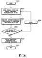
- Fig. 6 shows a process for an ONU selecting the wavelength based on this correspondence table.
- This wavelength selection process starts at S600.
- ONU 330 detects the downstream wavelengths not in use by sweeping tunable filter 334 through wavelength control circuit 340, and records them on the correspondence table in memory 342.
- the channels may be detected as the downstream wavelengths not in use, which do not exceed a predetermined signal power (P set ), for example.
- P set a predetermined signal power
- a light emitting pattern for notifying a wavelength not in use may be predetermined, and when that pattern is detected at the ONU, it may be determined as not-in-use.
- at least one downstream wavelength not in use may be detected.
- ONU 330 selects one downstream wavelength (e.g., ⁇ dk ) out of the downstream wavelengths not in use through wavelength control circuit 340, and assigns tunable filter 334 to that wavelength.
- the TX wavelength of tunable optical transmitter 338 is assigned to the upstream wavelength ( ⁇ uk ) corresponding to the downstream wavelength ( ⁇ dk ) through wavelength control circuit 340, and then transmitted.
- ONU 330 confirms presence or absence of the ACK signal back from OLT 310 on the downstream wavelength ( ⁇ dk ) assigned at tunable filter 334. If the ACK signal is not confirmed within a predetermined period of time, the detection of the downstream wavelength not in use is performed again via S608, and the optical signal with the corresponding upstream wavelength is then transmitted. In this case, the detection may be performed again including the same pair of wavelengths ( ⁇ dk and ⁇ uk ) not in use as in the previous turn, or the selection is made among the pairs of wavelengths not in use different from those in the previous turn. Further, by repeating this retransmission process after a random period of time, the probability can be reduced in selecting the same wavelength as other ONUs so that conflict at the OLT can be reduced.
- ONU 330 sets the pair of downstream and the upstream wavelengths ( ⁇ dk and ⁇ uk ) in memory 342 as the wavelengths to be used for TX and RX, and initiates communication at S610. ONU 330 then terminates the wavelength selection process at S612. After completion of the communication between the OSU and the ONU, the set pair of wavelengths may be released and the wavelength selection process may newly be performed at the time of the next communication, otherwise the set pair of wavelengths may fixedly be used between the certain OSU and ONU.
- the downstream wavelength e.g., ⁇ dk
- upstream wavelengths ⁇ dk and ⁇ uk
- the initial wavelength assignment can be performed with a simple algorithm without using monitoring light in a star-type wavelength multiplexed communication network.
- ONU 330 assigns tunable filter (TF) 334 to an initial wavelength grid by wavelength control circuit 340.
- ONU 330 monitors the RX power (P rec ) on the assigned grid.
- the monitored RX power is greater than a criterion power (P set ), and if it is greater, it is determined that the wavelength is in-use, and tunable filter 334 is assigned to the next grid by wavelength control circuit 340 and returned to S704 to monitor the RX power of this wavelength.
- P set a criterion power
- tunable filter 334 is assigned to the next grid by wavelength control circuit 340 and returned to S704 to monitor the RX power of this wavelength.
- the grid is detected as not-in-use, and a pair of upstream and downstream wavelengths corresponding to this grid is selected using the wavelength assignment table (WAT) (S710).
- WAT wavelength assignment table
- ONU 330 assigns the TX wavelength of tunable optical transmitter 338 to the upstream wavelength of the selected pair of wavelengths by wavelength control circuit 340, and transmits the optical signal towards the OLT. Further, at S714, ONU 330 assigns the RX wavelength of tunable filter 334 to the downstream wavelength of the selected pair of wavelengths by wavelength control circuit 340, and monitors the optical signal from the OLT. If a greater RX power (P rec ) than the predetermined criterion power (P set ) is detected on the selected downstream wavelength or the ACK signal from the OLT is detected, ONU 330 sets the selected pair of wavelengths for communication, and completes the wavelength selection process. Otherwise, ONU 330 stops transmission from tunable optical transmitter (LD) 338 in S718, and waits for a random period of time to elapse at S720, and then, repeats the wavelength selection process from the beginning by retuning to S702.
- LD tunable optical transmitter
- ONU #g and ONU #f access the OLT at the same time.
- the ONU #g and the ONU #f perform the detection of wavelengths not in use, and select the same pair of wavelengths ( ⁇ uj and ⁇ dj ). If the two ONUs coincidentally transmit the same upstream wavelength ( ⁇ uj ) to the OLT, a collision on the upstream wavelength occurs at the OLT.
- the occurrence of the collision may be notified to the ONU by not generating the downstream signal from the OLT, or it may take a form of action that the ONU retries if a certain light emitting pattern predetermined for notifying the occurrence of the collision is detected.
- the OLT is required to have a mechanism for detecting the occurrence of the collision, the means therefor is not limited. For example, by monitoring errors, it may be determined that the collision has occurred if the light power is greater than a predetermined value but the error is worse than a specified value, or by monitoring the clock extracted from the CDR (clock data recovery) circuit, it may be determined that the collision has occurred if the light power is greater than a predetermined value but the clock output is not normal.
- each of the two ONUs #f and #g performs the detection of the wavelengths not in use to select a pair of wavelengths not in use after a random period of time has elapsed. If the random periods of time are different between the ONUs #f and #g, the collision at the OLT would not occur, each selecting a different pair of wavelengths .
- the ONU #f selects the pair of wavelengths ⁇ uj and ⁇ dj first, and then, the ONU #g selects the pair of wavelengths ⁇ uk and ⁇ dk .
- the two ONUs having the responses can communicate with the OLT thereafter using the respective pairs of wavelengths.
- ONU 330 assigns tunable filter (TF) 334 to an initial wavelength grid by wavelength control circuit 340.
- ONU 330 monitors the RX power (P rec ) on the assigned grid, and if the greater signal than a predetermined criterion power (P set ) is detected, it is determined that the wavelength is in use.
- the monitored grid is the last grid, and if not, tunable filter 334 is assigned to the next grid by wavelength control circuit 340, and it is determined whether or not the present wavelength is now in use returning to S1004. If the monitored grid is the last grid at S1006, a pair of upstream and downstream wavelengths is randomly selected from the detected pairs of wavelengths not in use using the wavelength assignment table (WAT) (S1010).
- WAT wavelength assignment table
- ONU 330 assigns the TX wavelength for tunable optical transmitter 338 to the upstream wavelength of the selected pair of wavelengths by wavelength control circuit 340, and transmits the optical signal toward,s the OLT.
- ONU 330 assigns the RX wavelength for tunable filter 334 to the downstream wavelength of the selected pair of wavelengths by wavelength control circuit 340, and monitors the optical signal from the OLT. If a greater RX power (P rec ) than the predetermined criterion power (P set ) is detected at the selected downstream wavelength or the ACK signal from the OLT is detected, ONU 330 sets the selected pair of wavelengths for communication, and completes the wavelength selection process. Otherwise, ONU 330 stops the transmission from tunable optical transmitter (LD) 338 at S1018, and repeats the wavelength selection process from the beginning by returning to S1002. In this case, similarly to the retransmission process with the random delay described above, the retransmission process may be retried after the random period of time has elapsed.
- P rec the predetermined criterion power
- P set the predetermined criterion power
- ONU#g and ONU#f access OLT at the same time.
- the ONU#g and the ONU#f perform the detection of the wavelengths not in use, and select the same pair of wavelengths ( ⁇ uj and ⁇ dj ). If the two ONUs coincidentally transmit the same upstream wavelength ( ⁇ uj ) to the OLT, a collision on the upstream wavelength occurs at the OLT.
- the occurrence of the collision may be notified to the ONU by not generating the downstream signal from the OLT, or it may take a form of action that the ONU retries if a certain light emitting pattern predetermined for notifying the occurrence of the collision is detected.
- the OLT is required to have a mechanism for detecting the occurrence of the collision, the means therefor is not limited. For example, by monitoring errors, it may be determined that the collision has occurred if the light power is greater than a predetermined value but the error is worse than a specified value, or by monitoring the clock extracted from the CDR (clock data recovery) circuit, it may be determined that the collision has occurred if the light power is greater than a predetermined value but the clock output is not normal.
- each of the two ONUs #f and #g performs the detection of the wavelengths not in use, and each selects a pair of wavelengths randomly. If the pairs of wavelengths are different from each other, the OLT transmits the optical signals for responses with the corresponding downstream wavelengths to the ONUs, respectively.
- the ONU #f selects the pair of wavelengths ⁇ uj and ⁇ dj
- the ONU #g selects the pair of wavelengths ⁇ um and ⁇ dm .
- the two ONUs receiving the responses can communicate with the OLT thereafter using the respective pairs of wavelengths.
Description
- The present invention relates to an optical transmitter (TX) and receiver (RX) device used for wavelength multiplexed optical communication and a star-type network using the device.
- Conventionally, in a relay network using wavelength multiplexing scheme, monitoring light with a different wavelength from signal light is used to transmit wavelength information of the signal light and the like as monitoring information for monitor and control of wavelengths to be used (Patent Document 1).
-
Fig. 1 shows an exemplary configuration for monitor and control in such relay network. As shown in the figure, innetwork 100, wavelength-multiplexed signal light is transmitted fromWDM device A 110 toWDM device B 130 via linearoptical repeater 120. In this case, monitoring information such as power, wavelengths in use, and the number of the wavelengths for signal light is transmitted from monitor andcontrol circuit 112 to monitor and controlcircuit 132 via monitor andcontrol circuit 122 using monitoring light with a different wavelength from the signal light. - It is required to keep the light power constant on each channel at linear
optical repeater 120, even if more channels are provided innetwork 100 and the number of in-use wavelengths for the signal light is increased, .etc., in order to prevent degradation of the transmission characteristics in the network. In this case, the monitoring information of the signal light after provided with more channels is conveyed fromcontrol circuit 114 at the transmitting side through monitoringlight source 116. This monitoring light is multiplexed with the signal light atmultiplexer 20a, and transmitted out tooptical fiber 10. - Monitor and
control circuit 122 receives the monitoring light transmitted viaoptical fiber 10 atoptical receiver 128 and obtains the monitoring information. At the same time, monitor andcontrol circuit 122 monitors the total light power of the signal light at the output of linearoptical repeater 120, and computes the average power per channel based on the number of in-use wavelengths of the signal light obtained from the monitoring information.Monitoring control circuit 122 controls the output power of linearoptical repeater 120 so that the average power becomes a desired value. Accordingly, after provided with more channels, the light power on each channel can be kept constant at linearoptical repeater 120. - Further, this monitoring information is transmitted to monitor and control
circuit 132 through monitoringlight source 126, and received byoptical receiver 138. Based on the monitoring information,control circuit 134 controls the output power of an optical amplifier inWDM device B 130 so as to be a desired value. As such, the signal light is transmitted fromWDM device A 110 toWDM device B 130. - However, since the monitoring light is used in such a configuration, optical components such as
light sources multiplexers demultiplexers optical receivers -
Fig. 2 shows an exemplary configuration in which the configuration for monitor and control shown inFig. 1 is applied to a star-type wavelength multiplexed network.Network 200 is composed of an optical line terminal (OLT) 210 installed at a station, anoptical fiber 10 through which wavelength-multiplexed signal light and monitoring light propagate, apower splitter 30 for power-splitting the signal light and the monitoring light in the ratio of 1 to N, and N optical network units (ONUs) 230-1 to 230-N, each receiving the split signal light and the split monitoring light. - In the configuration, the monitoring information is transmitted from OLT 210 out to
optical fiber 10 usingmonitoring light source 214. The monitoring light is split into N atpower splitter 30, and transmitted to ONUs 230-1 to 230-N. Each ONU 230 receives the monitoring light withoptical receiver 242, and based on in-use wavelength information transmitted as the monitoring information,tunable filter 234 andoptical transmitter 238 are assigned bycontrol circuit 244 so as to receive a predetermined channel. - However, since the monitoring light is used in this configuration,
light source 214 andmultiplexer 22a are required in OLT 210, and the optical components such asdemultiplexer 22b andoptical receiver 242 are required in each ONU, which overall cost more. - Patent Document 1: Japanese Patent Laid-Open No.
10-51057 - Document
US 2004/0179855 discloses a wavelength division multiplexing transmission system and apparatuses used therein in which a remote apparatus to be newly added to a station apparatus autonomously sets a wavelength to be used in the remote apparatus. - Document
EP 0 810 752 discloses a method of controlling a wavelength of emitted light in a network system including detecting a wavelength falling within a continuous wavelength-tunable range of the light emitting means which does not interfere with any wavelengths of light being transmitted on the light transmission line, and emitting light at the detected wavelength. - Document
EP 0 438 155 discloses an optical communication equipment including a wavelength detection unit for detecting an unused first wavelength from the entire wavelength range to be commonly used. - The present invention has been made in view of the foregoing problem, and it is an object to provide a star-type wavelength multiplexed communication network using an optical transmitter and receiver (TX/RX) device capable of assigning the wavelengths without using monitoring light.
- To achieve such an object, according to the present invention, an optical TX/RX device and a method according to the respective independent claims are provided. Further details are set out in the dependent claims.
- According to the various aspects of the present invention, in a star-type network including a power splitter network, an optical TX/RX device capable of assigning the wavelengths can be provided without using monitoring light. Accordingly, the optical components relating to the transmission of the monitoring light such as a light source, a multiplexer, a demultiplexer, and an optical receiver can be eliminated. Further, the optical TX/RX device according to an aspect of the present invention is only required to monitor the signal power, and can be applied to various transmission frame
formats. Still further, since the wavelengths can automatically be assigned with a simple algorithm, it is especially advantageous for network expansion with small start-ups, with which economy is critical. -
- [
Fig. 1] Fig. 1 is a diagram showing an exemplary configuration for monitor and control in a relay system of a conventional wavelength multiplexed communication network; - [
Fig. 2] Fig. 2 is a diagram showing an exemplary configuration in which the configuration for monitor and control shown inFig. 1 is applied to a star-type wavelength multiplexed communication network; - [
Fig. 3] Fig. 3 is a diagram showing an exemplary configuration of a star-type wavelength multiplexed communication network according to an embodiment of the present invention; - [
Fig. 4] Fig. 4 is a diagram showing an example of wavelength allocation for upstream and downstream in a star-type wavelength multiplexed communication network according to an embodiment of the present invention; - [
Fig. 5] Fig. 5 is a diagram showing an exemplary configuration of ONU according to an embodiment of the present invention; - [
Fig. 6] Fig. 6 is a flowchart showing a wavelength selection process between ONU and OLT according to an embodiment of the present invention; - [
Fig. 7] Fig. 7 is a flowchart showing a wavelength selection process for randomly selecting a delay time between ONU and OLT according to an embodiment of the present invention; - [
Fig. 8] Fig. 8 is a time chart showing a wavelength selection process for randomly selecting a delay time between ONU and OLT according to an embodiment of the present invention; - [
Fig. 9] Fig. 9 is another time chart showing a wavelength selection process for randomly selecting a delay time between ONU and OLT according to an embodiment of the present invention; - [
Fig. 10] Fig. 10 is a flowchart showing a wavelength selection process for randomly selecting a wavelength between ONU and OLT according to an embodiment of the present invention; - [
Fig. 11] Fig. 11 is a time chart showing a wavelength selection process for randomly selecting a wavelength between ONU and OLT according to an embodiment of the present invention; and - [
Fig. 12] Fig. 12 is another time chart showing a wavelength selection process for randomly selecting a wavelength between ONU and OLT according to an embodiment of the present invention. - Hereinafter, embodiments of the present invention will be described in detail with reference to the drawings.
-
Fig. 3 shows an exemplary configuration of a star-type network using an optical TX/RX device according to the present invention.Network 300 is composed of an optical line terminal (OLT) 310 for transmitting and receiving wavelength-multiplexed signal light, anoptical fiber 10 through which the signal light propagates, apower splitter 30 for combining or splitting the optical signal with 1 to N, and N optical network units (ONUs) (optical TX/RX devices) 330-1 to 330-N each transmitting and receiving optical signal. - OLT 310 comprises N optical subscriber units (OSUs) 320-1 to 320-N each transmitting and receiving signal light with an assigned wavelength, a
wavelength control circuit 314 for controlling the wavelengths of signal light used for TX and RX by the OSUs, and a wavelength multi/demultiplexer 312 for multiplexing the optical signals from the OSUs and demultiplexing the optical signals from the ONUs. OSUs 320-1 to 320-N are assigned with different wavelengths, respectively, bywavelength control circuit 314. In this case,wavelength control circuit 314 may assign these wavelengths to the OSUs in fixed or dynamic way. Alternatively, it may be configured to use an OSU with a prefixed TX and RX wavelengths and stabilize the wavelengths by the wavelength control circuit. An optical signal from an OSU assigned with a wavelength is wavelength-multiplexed by wavelength multi/demultiplexer 312 and then transmitted out tooptical fiber 10. - The wavelength-multiplexed signal light from OLT 310 is split into N paths of
power splitter 30 viaoptical fiber 10, and then transmitted to ONUs 330-1 to 330-N for the subscribers on the respective paths. Here, each ONU receives the optical signal with the downstream wavelength selected bywavelength control circuit 340 out of the wavelength-multiplexed signal light from the OLT. Also, each ONU transmits the optical signal to the OLT using the upstream wavelength selected bywavelength control circuit 340. The signal light from each ONU is combined atpower splitter 30, and transmitted to OLT 310 viaoptical fiber 10. The signal light from the ONUs is demultiplexed by-wavelength at wavelength multi/demultiplexer 312, and transmitted to the respective OSUs. -
Fig. 4 shows an example of wavelength allocation for upstream and downstream in such star-type network. As shown in the figure, the downstream wavelengths λd1 to λdN and the upstream wavelengths λu1 to λuN are allocated on the ITU grid. AlthoughFig. 4 shows an example of allocating the upstream wavelengths on the shorter wavelength side and the downstream wavelengths on the longer wavelength side, it should be noted that any arbitrary wavelength allocations may be used. -
Fig. 5 shows an exemplary configuration of the ONU according to the present invention.ONU 330 transmits and receives the signal light withOLT 310 over the upstream and the downstream wavelengths. Wavelength multi/demultiplexer 332 multiplexes and demultiplexes the upstream wavelength and the downstream wavelength. A desired wavelength out of the wavelength-multiplexed downstream wavelengths is selected via tunable filter (TF) 334 in accordance with the assignment ofwavelength control circuit 340. The signal light of the selected downstream wavelength is converted into an electric signal byoptical receiver 336 and demodulated as a RX data signal. - On the other hand, the TX data signal is entered into tunable
optical transmitter 338, and then transmitted as optical signal with a desired wavelength in accordance with assignment ofwavelength control circuit 340. This upstream signal light is transmitted to the OLT via wavelength multi/demultiplexer 332. - Next, a procedure to assign the upstream and the downstream wavelengths between the OLT and the ONUs will be described in the exemplary configuration shown in
Figs. 3 and5 . Firstly, in the wavelength allocation of the upstream and the downstream inFig. 4 , assume that a pair of the upstream and the downstream wavelengths is assigned for each OSU and ONU as in the following wavelength assignment table (WAT). -
Table 1: Correspondence between upstream and downstream wavelengths and status of use Upstream wavelength Downstream wavelength Status λu1 λd1 in use λu2 λd2 not in use ... ... ... λuk λdk not in use ... ... ... λuN λdN not in use - Each
ONU memory 342 stores this correspondence table between the upstream wavelengths and the downstream wavelengths. By using this table to determine the status of use on the downstream wavelengths, the ONU can select the pair of the upstream and the downstream wavelengths not in use and initiate communication. Although this correspondence table shows only the in-use/not-in-use status of the pairs of wavelengths, it is not limited thereto, and the table may be maintained in association with which wavelength is assigned to which OSU and ONU pair so that quick countermeasures against failure may be taken, for example. Also, the table may be maintained in association with the wavelengths and the transmission rates so that multiple services with different transmission rates can be accommodated. -
Fig. 6 shows a process for an ONU selecting the wavelength based on this correspondence table. This wavelength selection process starts at S600. At S602,ONU 330 detects the downstream wavelengths not in use by sweepingtunable filter 334 throughwavelength control circuit 340, and records them on the correspondence table inmemory 342. Here, in detecting the wavelengths not in use, the channels may be detected as the downstream wavelengths not in use, which do not exceed a predetermined signal power (Pset), for example. Alternatively, a light emitting pattern for notifying a wavelength not in use may be predetermined, and when that pattern is detected at the ONU, it may be determined as not-in-use. Further, while all of the downstream wavelengths not in use may be detected, at least one downstream wavelength not in use may be detected. Then, at S604,ONU 330 selects one downstream wavelength (e.g., λdk) out of the downstream wavelengths not in use throughwavelength control circuit 340, and assignstunable filter 334 to that wavelength. In conjunction therewith, the TX wavelength of tunableoptical transmitter 338 is assigned to the upstream wavelength (λuk) corresponding to the downstream wavelength (λdk) throughwavelength control circuit 340, and then transmitted. - At S606,
ONU 330 confirms presence or absence of the ACK signal back fromOLT 310 on the downstream wavelength (λdk) assigned attunable filter 334. If the ACK signal is not confirmed within a predetermined period of time, the detection of the downstream wavelength not in use is performed again via S608, and the optical signal with the corresponding upstream wavelength is then transmitted. In this case, the detection may be performed again including the same pair of wavelengths (λdk and λuk) not in use as in the previous turn, or the selection is made among the pairs of wavelengths not in use different from those in the previous turn. Further, by repeating this retransmission process after a random period of time, the probability can be reduced in selecting the same wavelength as other ONUs so that conflict at the OLT can be reduced. - If the ACK signal from the OLT is received on the downstream wavelength (e.g., λdk) assigned at
tunable filter 334,ONU 330 sets the pair of downstream and the upstream wavelengths (λdk and λuk) inmemory 342 as the wavelengths to be used for TX and RX, and initiates communication at S610.ONU 330 then terminates the wavelength selection process at S612. After completion of the communication between the OSU and the ONU, the set pair of wavelengths may be released and the wavelength selection process may newly be performed at the time of the next communication, otherwise the set pair of wavelengths may fixedly be used between the certain OSU and ONU. - As described hereinabove, according to the wavelength selection process of the present invention, the initial wavelength assignment can be performed with a simple algorithm without using monitoring light in a star-type wavelength multiplexed communication network.
- Next, as a retransmission process in the case of no response, a method for selecting a pair of wavelengths not in use after a random delay will be described.
Fig. 7 shows this process. Firstly, at S702,ONU 330 assigns tunable filter (TF) 334 to an initial wavelength grid bywavelength control circuit 340. At S704,ONU 330 monitors the RX power (Prec) on the assigned grid. - Then, at S706, it is determined whether or not the monitored RX power is greater than a criterion power (Pset), and if it is greater, it is determined that the wavelength is in-use, and
tunable filter 334 is assigned to the next grid bywavelength control circuit 340 and returned to S704 to monitor the RX power of this wavelength. At S706, if the monitored RX power is weaker than the predetermined criterion power, the grid is detected as not-in-use, and a pair of upstream and downstream wavelengths corresponding to this grid is selected using the wavelength assignment table (WAT) (S710). - At S712,
ONU 330 assigns the TX wavelength of tunableoptical transmitter 338 to the upstream wavelength of the selected pair of wavelengths bywavelength control circuit 340, and transmits the optical signal towards the OLT. Further, at S714,ONU 330 assigns the RX wavelength oftunable filter 334 to the downstream wavelength of the selected pair of wavelengths bywavelength control circuit 340, and monitors the optical signal from the OLT. If a greater RX power (Prec) than the predetermined criterion power (Pset) is detected on the selected downstream wavelength or the ACK signal from the OLT is detected,ONU 330 sets the selected pair of wavelengths for communication, and completes the wavelength selection process. Otherwise,ONU 330 stops transmission from tunable optical transmitter (LD) 338 in S718, and waits for a random period of time to elapse at S720, and then, repeats the wavelength selection process from the beginning by retuning to S702. - Next, with reference to
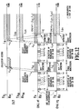
Figs. 8 and9 , the operation is described in which ONU #g and ONU #f access the OLT at the same time. Assume that the ONU #g and the ONU #f perform the detection of wavelengths not in use, and select the same pair of wavelengths (λuj and λdj). If the two ONUs coincidentally transmit the same upstream wavelength (λuj) to the OLT, a collision on the upstream wavelength occurs at the OLT. When the collision occurs, the occurrence of the collision may be notified to the ONU by not generating the downstream signal from the OLT, or it may take a form of action that the ONU retries if a certain light emitting pattern predetermined for notifying the occurrence of the collision is detected. The OLT is required to have a mechanism for detecting the occurrence of the collision, the means therefor is not limited. For example, by monitoring errors, it may be determined that the collision has occurred if the light power is greater than a predetermined value but the error is worse than a specified value, or by monitoring the clock extracted from the CDR (clock data recovery) circuit, it may be determined that the collision has occurred if the light power is greater than a predetermined value but the clock output is not normal. In the example ofFigs. 8 and9 , if the collision occurs, each of the two ONUs #f and #g performs the detection of the wavelengths not in use to select a pair of wavelengths not in use after a random period of time has elapsed. If the random periods of time are different between the ONUs #f and #g, the collision at the OLT would not occur, each selecting a different pair of wavelengths . InFigs. 8 and9 , the ONU #f selects the pair of wavelengths λuj and λdj first, and then, the ONU #g selects the pair of wavelengths λuk and λdk. The two ONUs having the responses can communicate with the OLT thereafter using the respective pairs of wavelengths. - Next, as a retransmission process in the case of no response, a method will be described, which randomly selects a pair of wavelengths to use out of pairs of wavelengths not in use.
Fig. 10 shows this process. Firstly, at S1002,ONU 330 assigns tunable filter (TF) 334 to an initial wavelength grid bywavelength control circuit 340. At S1004,ONU 330 monitors the RX power (Prec) on the assigned grid, and if the greater signal than a predetermined criterion power (Pset) is detected, it is determined that the wavelength is in use. - Then, at S1006, it is determined whether or not the monitored grid is the last grid, and if not,
tunable filter 334 is assigned to the next grid bywavelength control circuit 340, and it is determined whether or not the present wavelength is now in use returning to S1004. If the monitored grid is the last grid at S1006, a pair of upstream and downstream wavelengths is randomly selected from the detected pairs of wavelengths not in use using the wavelength assignment table (WAT) (S1010). - At S1012,
ONU 330 assigns the TX wavelength for tunableoptical transmitter 338 to the upstream wavelength of the selected pair of wavelengths bywavelength control circuit 340, and transmits the optical signal toward,s the OLT. - Further, at S1014,
ONU 330 assigns the RX wavelength fortunable filter 334 to the downstream wavelength of the selected pair of wavelengths bywavelength control circuit 340, and monitors the optical signal from the OLT. If a greater RX power (Prec) than the predetermined criterion power (Pset) is detected at the selected downstream wavelength or the ACK signal from the OLT is detected,ONU 330 sets the selected pair of wavelengths for communication, and completes the wavelength selection process. Otherwise,ONU 330 stops the transmission from tunable optical transmitter (LD) 338 at S1018, and repeats the wavelength selection process from the beginning by returning to S1002. In this case, similarly to the retransmission process with the random delay described above, the retransmission process may be retried after the random period of time has elapsed. - Next, with reference to
Figs. 11 and12 , the operation is described in which ONU#g and ONU#f access OLT at the same time. Assume that the ONU#g and the ONU#f perform the detection of the wavelengths not in use, and select the same pair of wavelengths (λuj and λdj). If the two ONUs coincidentally transmit the same upstream wavelength (λuj) to the OLT, a collision on the upstream wavelength occurs at the OLT. - When the collision occurs, the occurrence of the collision may be notified to the ONU by not generating the downstream signal from the OLT, or it may take a form of action that the ONU retries if a certain light emitting pattern predetermined for notifying the occurrence of the collision is detected. The OLT is required to have a mechanism for detecting the occurrence of the collision, the means therefor is not limited. For example, by monitoring errors, it may be determined that the collision has occurred if the light power is greater than a predetermined value but the error is worse than a specified value, or by monitoring the clock extracted from the CDR (clock data recovery) circuit, it may be determined that the collision has occurred if the light power is greater than a predetermined value but the clock output is not normal. In the example of
Figs. 11 and12 , each of the two ONUs #f and #g performs the detection of the wavelengths not in use, and each selects a pair of wavelengths randomly. If the pairs of wavelengths are different from each other, the OLT transmits the optical signals for responses with the corresponding downstream wavelengths to the ONUs, respectively. InFigs. 11 and12 , the ONU #f selects the pair of wavelengths λuj and λdj, and the ONU #g selects the pair of wavelengths λum and λdm. The two ONUs receiving the responses can communicate with the OLT thereafter using the respective pairs of wavelengths. - Hereinabove, the present invention is specifically described with certain embodiments. However, in view of many embodiments applicable for the principle of the present invention, the embodiments described herein are merely examples and are not intended to limit the scope of the invention. The embodiments illustrated herein may be modified in the configurations and details without departing from the scope of the present invention. Further, components and procedures for the purpose of descriptions may be modified, supplemented, or reordered without departing from the scope of the present invention.
Claims (10)
- An optical TX/RX device for transmitting and receiving wavelength-multiplexed signal light, comprising:an optical RX means (336) capable of varying a RX wavelength;an optical TX means (338) capable of varying a TX wavelength;characterized bya storage means (342) provided with a correspondence table between RX wavelengths selectable for the optical RX means and TX wavelengths selectable for the optical TX meansa detection means for detecting RX wavelengths not in use among the RX wavelengths selectable for the optical RX means; anda wavelength control means (340) for assigning the RX wavelength of the optical RX means to one of the RX wavelengths not in use detected by the detection means and for selecting one of the selectable TX wavelengths corresponding to the assigned RX wavelength based on the correspondence table.
- The optical TX/RX device according to Claim 1, wherein the optical RX means includes:a tunable filter capable of tuning the RX wavelength, andan optical receiver for receiving the RX wavelength through the tunable filter.
- The optical TX/RX device according to Claim 1 or 2, wherein
the detection means scans the RX wavelengths selectable for the optical RX means and detects the RX wavelengths not in use by measuring RX power on each RX wavelengths. - The optical TX/RX device according to any one of Claims 1 to 3, whereinthe optical TX means transmits optical signals on the assigned TX wavelength,the optical RX means receives response signals to the optical signal on the assigned RX wavelength,the optical TX/RX device initiates communication via the optical TX means and the optical RX means using the assigned TX wavelength and RX wavelength if the optical RX means receives the response signal, andthe optical TX/RX device is configured to detect the wavelength not in use by the detection means, to assign the RX wavelength of the optical RX means to one of the detected RX wavelengths by the wavelength control means and to assign the TX wavelength of the optical TX means to a TX wavelength corresponding to the RX wavelength, after a random period of time has elapsed, if the optical RX means receives no response signal.
- The optical TX/RX device according to any one of Claims 1 to 3, whereinthe optical TX means transmits optical signals on the assigned TX wavelength,the optical RX means receives response signals to the optical signal on the assigned RX wavelength,the optical TX/RX device initiates communication via the optical TX means and the optical RX means using the assigned TX wavelength and RX wavelength if the optical RX means receives the response signal, andthe optical TX/RX device is configured to detect the wavelengths not in use by the detection means, to randomly assign the RX wavelength of the optical RX means to one of the detected RX wavelengths by the wavelength control means and to assign the TX wavelength of the optical TX means to a TX wavelength corresponding to the RX wavelength, if the optical RX means receives no response signal.
- A network comprising:a plurality of the optical TX/RX devices according to any one of Claims 1 to 5; andan optical line terminal connected with the plurality of the optical TX/RX devices via a power splitter.
- A method of assigning wavelengths for an optical TX/RX device characterized by having a correspondence table between RX wavelengths selectable for the optical TX/RX device and TX wavelengths selectable for the optical TX/RX device, the optical TX/RX device connects to a network including a plurality of optical TX/RX devices capable of varying respective upstream and downstream wavelengths, and an optical line terminal connected with the plurality of optical TX/RX devices via a power splitter, the method includes:(a) detecting (S602) downstream wavelengths not in use among the RX wavelengths selectable for the optical TX/RX device by detecting presence or absence of the downstream wavelengths from the optical line terminal via the power splitter;(b) selecting (S604) one of the detected downstream wavelengths;(c) selecting one of the selectable TX wavelengths corresponding to the selected downstream wavelength as an upstream wavelength based on the correspondence table;(d) transmitting a signal light on the selected upstream wavelength;(e) detecting (S606) a response to the transmitted signal light on the selected downstream wavelength; and(f) initiating (S610) communication with the optical line terminal using the selected downstream wavelength and the selected upstream wavelength if the response is detected.
- The method of assigning wavelengths according to Claim 7, comprising:(g) repeating the steps (a) to (e) if the response is not detected.
- The method of assigning wavelengths according to one of Claims 7 and 8, wherein
the repeating step (g) repeats the steps (a) to (e) after a random period of time has elapsed. - The method of assigning wavelengths according to any one of Claims 7 to 9, wherein
selecting step (b) selects a downstream wavelength randomly out of the detected downstream wavelengths.
Applications Claiming Priority (2)
| Application Number | Priority Date | Filing Date | Title |
|---|---|---|---|
| JP2006019043 | 2006-01-27 | ||
| PCT/JP2007/051282 WO2007086514A1 (en) | 2006-01-27 | 2007-01-26 | Optical wavelength multiplexing access system |
Publications (3)
| Publication Number | Publication Date |
|---|---|
| EP1978653A1 EP1978653A1 (en) | 2008-10-08 |
| EP1978653A4 EP1978653A4 (en) | 2011-03-16 |
| EP1978653B1 true EP1978653B1 (en) | 2018-06-20 |
Family
ID=38309300
Family Applications (1)
| Application Number | Title | Priority Date | Filing Date |
|---|---|---|---|
| EP07707514.1A Active EP1978653B1 (en) | 2006-01-27 | 2007-01-26 | Optical wavelength multiplexing access system |
Country Status (7)
| Country | Link |
|---|---|
| US (1) | US8014672B2 (en) |
| EP (1) | EP1978653B1 (en) |
| JP (1) | JP4827850B2 (en) |
| KR (1) | KR100917852B1 (en) |
| CN (1) | CN101213776A (en) |
| CA (1) | CA2601559C (en) |
| WO (1) | WO2007086514A1 (en) |
Cited By (1)
| Publication number | Priority date | Publication date | Assignee | Title |
|---|---|---|---|---|
| WO2023217380A1 (en) * | 2022-05-12 | 2023-11-16 | Telefonaktiebolaget Lm Ericsson (Publ) | Optical transceiver and method of setting operating wavelengths |
Families Citing this family (54)
| Publication number | Priority date | Publication date | Assignee | Title |
|---|---|---|---|---|
| US7903973B1 (en) | 2005-12-23 | 2011-03-08 | Lockheed Martin Corporation | Dynamic temporal duration optical transmission privacy |
| US7792427B1 (en) | 2006-01-30 | 2010-09-07 | Lockheed Martin Corporation | Optical code division multiple access data storage and retrieval |
| US7991288B1 (en) * | 2006-02-07 | 2011-08-02 | Lockheed Martin Corporation | Optical code division multiple access data storage encryption and retrieval |
| JP4388556B2 (en) | 2007-01-09 | 2009-12-24 | 株式会社日立コミュニケーションテクノロジー | Passive optical network system and wavelength allocation method |
| JP2009060532A (en) * | 2007-09-03 | 2009-03-19 | Nippon Telegr & Teleph Corp <Ntt> | Variable-wavelength optical transceiver, and optical transmission system |
| JP5053121B2 (en) * | 2008-02-22 | 2012-10-17 | 日本電信電話株式会社 | Optical transceiver on the optical terminal side (OSU) |
| JP4994300B2 (en) * | 2008-05-29 | 2012-08-08 | 日本電信電話株式会社 | Optical termination device |
| JP5144564B2 (en) * | 2009-03-12 | 2013-02-13 | 富士通テレコムネットワークス株式会社 | Wavelength multiplexing transmission system and wavelength multiplexing transmission control method |
| WO2010107350A1 (en) * | 2009-03-20 | 2010-09-23 | Telefonaktiebolaget Lm Ericsson (Publ) | Method and devices for automatic tuning in wdm-pon |
| DE102009021010B4 (en) | 2009-05-12 | 2012-03-01 | Adva Ag Optical Networking | Optical WDM transceiver and optical transceiver unit therefor |
| JP4909376B2 (en) * | 2009-05-19 | 2012-04-04 | 株式会社日立製作所 | Passive optical network system and wavelength allocation method |
| US8811819B2 (en) * | 2009-06-16 | 2014-08-19 | Hitachi, Ltd. | Optical multiplexing terminal device, wavelength multiplexing passive optical network system and downlink wavelength transmission method |
| JP5511233B2 (en) * | 2009-06-18 | 2014-06-04 | Nttエレクトロニクス株式会社 | Optical signal determination device, terminal device connection method, terminal device, and fixed wavelength light source selection method |
| JP5457557B2 (en) * | 2009-07-31 | 2014-04-02 | テレフオンアクチーボラゲット エル エム エリクソン(パブル) | Apparatus and method for operating a wavelength division multiple access network |
| KR20110018826A (en) | 2009-08-18 | 2011-02-24 | 한국전자통신연구원 | The system of open optical access network |
| US9174191B2 (en) * | 2009-08-19 | 2015-11-03 | Telefonaktiebolaget L M Ericsson (Publ) | Optical networks |
| ES2396185T3 (en) * | 2009-08-21 | 2013-02-19 | Nokia Siemens Networks Oy | Data processing in an optical network |
| JP5435223B2 (en) * | 2009-10-13 | 2014-03-05 | 日本電気株式会社 | Wavelength division multiplexing transmission apparatus and signal light monitoring method thereof |
| WO2011050855A1 (en) * | 2009-11-02 | 2011-05-05 | Nokia Siemens Networks Oy | Method and device for processing data in an optical network |
| CN102065343B (en) * | 2009-11-16 | 2013-10-02 | 华为技术有限公司 | Wavelength selection method, device and system |
| EP2388935A1 (en) * | 2010-05-19 | 2011-11-23 | Nokia Siemens Networks Oy | Optical network unit, method for processing data in an optical network and communication system |
| US8971704B2 (en) | 2009-12-03 | 2015-03-03 | Telefonaktiebolaget L M Ericsson (Publ) | Optical networks |
| JP5351008B2 (en) * | 2009-12-28 | 2013-11-27 | 日本電信電話株式会社 | Optical communication system, station side device, subscriber side device, and optical communication method |
| JP5600028B2 (en) * | 2010-04-15 | 2014-10-01 | 日本電信電話株式会社 | Subscriber side apparatus, station side apparatus, optical communication system, and optical communication method |
| EP2564531B2 (en) * | 2010-04-28 | 2017-03-01 | Telefonaktiebolaget LM Ericsson (publ) | Optical access network |
| EP2538591B1 (en) * | 2011-06-21 | 2013-08-07 | Telefonaktiebolaget L M Ericsson (publ) | Wavelength division multiplexed passive optical network apparatus and methods of configuration |
| JP5150758B2 (en) * | 2011-09-05 | 2013-02-27 | 株式会社日立製作所 | Optical termination device and optical network unit |
| US9485026B2 (en) * | 2011-09-16 | 2016-11-01 | OE Solutions Co., Ltd. | Scheme for remote control of the wavelength of a tunable transmitter in a smart transceiver |
| KR101571987B1 (en) * | 2011-12-21 | 2015-12-04 | 니폰 덴신 덴와 가부시끼가이샤 | Bandwidth allocation device and bandwidth allocation method |
| WO2013170907A1 (en) * | 2012-05-14 | 2013-11-21 | Telefonaktiebolaget L M Ericsson (Publ) | Passive optical networks and method of configuring transmission wavelengths therein |
| US9191110B2 (en) * | 2012-06-11 | 2015-11-17 | Verizon Patent And Licensing Inc. | Reducing coherent noise in single fiber transceivers |
| EP2863564A4 (en) * | 2012-06-13 | 2015-04-29 | Huawei Tech Co Ltd | Wavelength configuration method, system, and device for multi-wavelength passive optical network |
| AU2012385350B2 (en) * | 2012-07-13 | 2016-02-04 | Huawei Technologies Co., Ltd. | Wavelength negotiation method and apparatus of multi-wavelength passive optical network, and multi-wavelength passive optical network system |
| US20140233954A1 (en) * | 2013-02-21 | 2014-08-21 | Electronics And Telecommunications Research Institute | Link establishment method for multi-wavelength passive optical network system |
| US9118984B2 (en) * | 2013-03-15 | 2015-08-25 | International Business Machines Corporation | Control plane for integrated switch wavelength division multiplexing |
| WO2015027486A1 (en) | 2013-08-30 | 2015-03-05 | 华为技术有限公司 | Uplink signal transmission method, processing device and system |
| DE102013110804B3 (en) | 2013-09-30 | 2014-12-18 | Deutsche Telekom Ag | Central network entity for a wavelength division multiplex communication network |
| US9768908B2 (en) * | 2013-10-25 | 2017-09-19 | Nippon Telegraph And Telephone Corporation | Protection method and optical communication system |
| KR101489470B1 (en) | 2013-12-02 | 2015-02-04 | 주식회사 쏠리드 | Optical time domain reflectometer using polymer-based wavelength tunable laser diode |
| JP6178264B2 (en) * | 2014-03-07 | 2017-08-09 | 日本電信電話株式会社 | Wavelength monitoring method, wavelength monitoring system, and parent node |
| JP5761415B1 (en) * | 2014-03-26 | 2015-08-12 | 沖電気工業株式会社 | Subscriber side device registration method |
| WO2015186194A1 (en) * | 2014-06-03 | 2015-12-10 | 三菱電機株式会社 | Master station device, slave station device, optical communication system, and wavelength allocation method |
| WO2016070353A1 (en) * | 2014-11-05 | 2016-05-12 | 华为技术有限公司 | Optical port auto-negotiation method, optical module, office side device, and terminal device |
| WO2016114199A1 (en) * | 2015-01-16 | 2016-07-21 | 日本電信電話株式会社 | Station-side device and wavelength control method |
| US10014938B2 (en) * | 2015-10-23 | 2018-07-03 | Calix, Inc. | Optical network terminal wavelength notification |
| CN106817167B (en) * | 2015-11-27 | 2019-06-28 | 菲尼萨公司 | The optical wavelength of transceiver adapts to automatically |
| JP6491800B2 (en) * | 2016-06-20 | 2019-03-27 | 日本電信電話株式会社 | Optical transceiver and control method |
| US10397672B2 (en) * | 2016-06-20 | 2019-08-27 | Cable Television Laboratories, Inc. | Systems and methods for intelligent edge to edge optical system and wavelength provisioning |
| US10200123B2 (en) * | 2016-06-20 | 2019-02-05 | Cable Television Laboratories, Inc. | System and methods for distribution of heterogeneous wavelength multiplexed signals over optical access network |
| WO2017221878A1 (en) * | 2016-06-20 | 2017-12-28 | 日本電信電話株式会社 | Optical transceiver and control method |
| WO2018009649A1 (en) * | 2016-07-06 | 2018-01-11 | Google Llc | Battery fast-charging system |
| US10476625B2 (en) * | 2016-10-31 | 2019-11-12 | Electronics And Telecommunications Research Institute | Optical network system using wavelength channels included in O-band |
| US11039229B2 (en) * | 2017-08-29 | 2021-06-15 | Cable Television Laboratories, Inc. | Systems and methods for coherent optics ranging and sensing |
| JP2019097108A (en) * | 2017-11-27 | 2019-06-20 | 富士通株式会社 | Optical transmission device, optical transmission system and optical transmission method |
Family Cites Families (21)
| Publication number | Priority date | Publication date | Assignee | Title |
|---|---|---|---|---|
| US4797879A (en) * | 1987-06-05 | 1989-01-10 | American Telephone And Telegraph Company At&T Bell Laboratories | Packet switched interconnection protocols for a star configured optical lan |
| US5212577A (en) * | 1990-01-19 | 1993-05-18 | Canon Kabushiki Kaisha | Optical communication equipment and optical communication method |
| JP2833661B2 (en) * | 1990-01-19 | 1998-12-09 | キヤノン株式会社 | Optical communication equipment |
| EP0438155B1 (en) * | 1990-01-19 | 1997-05-02 | Canon Kabushiki Kaisha | Optical communication equipment |
| DE69434078T2 (en) * | 1993-03-11 | 2005-11-03 | At & T Corp. | Optical network with remote terminal query and optical network unit that transforms wavelengths |
| US5838470A (en) * | 1995-07-27 | 1998-11-17 | University Technology Corporation | Optical wavelength tracking receiver |
| FR2739510A1 (en) * | 1995-10-02 | 1997-04-04 | Canon Kk | Digital communication converter for frame transmission system |
| JP3368126B2 (en) * | 1995-12-21 | 2003-01-20 | キヤノン株式会社 | Communication method, communication device, and network system |
| US6025947A (en) * | 1996-05-02 | 2000-02-15 | Fujitsu Limited | Controller which controls a variable optical attenuator to control the power level of a wavelength-multiplexed optical signal when the number of channels are varied |
| JP3306700B2 (en) | 1996-05-02 | 2002-07-24 | 富士通株式会社 | Optical amplifier and wavelength division multiplexing optical transmission system |
| JP3566496B2 (en) * | 1996-05-27 | 2004-09-15 | キヤノン株式会社 | Wavelength control method and network system using the same |
| JP3214831B2 (en) | 1998-03-13 | 2001-10-02 | カネボウ株式会社 | Data processing device |
| US6822743B2 (en) * | 2001-03-07 | 2004-11-23 | Paul Trinh | Integrated-optic channel monitoring |
| JP2003174432A (en) * | 2001-12-06 | 2003-06-20 | Fujitsu Ltd | Light wavelength multiplex transmission system |
| JP4955189B2 (en) * | 2003-03-12 | 2012-06-20 | 日本電気株式会社 | Wavelength division multiplexing transmission system and remote device and station device used in the system |
| WO2004093352A1 (en) * | 2003-04-15 | 2004-10-28 | Fujitsu Limited | Optical transmission device |
| JP4642623B2 (en) * | 2005-09-30 | 2011-03-02 | 富士通株式会社 | Wavelength division multiplexer |
| JP4704842B2 (en) * | 2005-08-01 | 2011-06-22 | 株式会社日立製作所 | WDM type PON system |
| US7590353B2 (en) * | 2005-08-31 | 2009-09-15 | Fujitsu Limited | System and method for bandwidth allocation in an optical light-trail |
| JP4410789B2 (en) * | 2006-12-08 | 2010-02-03 | 株式会社日立コミュニケーションテクノロジー | Passive optical network system, optical termination device and optical network unit |
| JP4388556B2 (en) * | 2007-01-09 | 2009-12-24 | 株式会社日立コミュニケーションテクノロジー | Passive optical network system and wavelength allocation method |
-
2007
- 2007-01-26 CA CA2601559A patent/CA2601559C/en active Active
- 2007-01-26 US US11/815,031 patent/US8014672B2/en active Active
- 2007-01-26 EP EP07707514.1A patent/EP1978653B1/en active Active
- 2007-01-26 KR KR1020077017555A patent/KR100917852B1/en active IP Right Grant
- 2007-01-26 WO PCT/JP2007/051282 patent/WO2007086514A1/en active Application Filing
- 2007-01-26 CN CNA2007800000461A patent/CN101213776A/en active Pending
- 2007-01-26 JP JP2007535942A patent/JP4827850B2/en active Active
Non-Patent Citations (1)
| Title |
|---|
| None * |
Cited By (1)
| Publication number | Priority date | Publication date | Assignee | Title |
|---|---|---|---|---|
| WO2023217380A1 (en) * | 2022-05-12 | 2023-11-16 | Telefonaktiebolaget Lm Ericsson (Publ) | Optical transceiver and method of setting operating wavelengths |
Also Published As
| Publication number | Publication date |
|---|---|
| EP1978653A4 (en) | 2011-03-16 |
| KR100917852B1 (en) | 2009-09-18 |
| CA2601559C (en) | 2013-04-30 |
| KR20070101296A (en) | 2007-10-16 |
| JPWO2007086514A1 (en) | 2009-06-25 |
| US20090016726A1 (en) | 2009-01-15 |
| WO2007086514A1 (en) | 2007-08-02 |
| CA2601559A1 (en) | 2007-08-02 |
| US8014672B2 (en) | 2011-09-06 |
| JP4827850B2 (en) | 2011-11-30 |
| CN101213776A (en) | 2008-07-02 |
| EP1978653A1 (en) | 2008-10-08 |
Similar Documents
| Publication | Publication Date | Title |
|---|---|---|
| EP1978653B1 (en) | Optical wavelength multiplexing access system | |
| KR101885372B1 (en) | System and method of onu power levelling for time and wavelength division multiplexing passive optical network | |
| US7831118B2 (en) | Coarse wavelength division multiplexing optical transmission system, and coarse wavelength division multiplexing optical transmission method | |
| JP3060994B2 (en) | Output port switching device in N-WDM system | |
| US9525507B2 (en) | Method of tuning wavelength in time and wavelength division multiplexing-passive optical network (TWDM-PON) | |
| JP4499576B2 (en) | Optical wavelength division multiplexing system, optical termination device and optical network unit | |
| US9768862B2 (en) | Slave station apparatus, master station apparatus, control device, communication system, and wavelength switching method | |
| EP1347590A2 (en) | Wavelength division multiplexing passive optical network system | |
| CN102577428B (en) | For regulating the method and apparatus of the laser in light net | |
| JP2019097108A (en) | Optical transmission device, optical transmission system and optical transmission method | |
| US20150055957A1 (en) | Method of determining physical layer wavelength of tunable optical network unit (onu) in time and wavelength division multiplexed passive optical network (twdm-pon) | |
| WO2011122700A1 (en) | Wavelength-division-multiplexing passive-optical-network system, subscriber-side termination apparatus, and wavelength changing method | |
| JP5261164B2 (en) | Optical transmission system | |
| JP4994300B2 (en) | Optical termination device | |
| KR20140127167A (en) | Controlling method for mitigating rogue ONU in a hybrid system | |
| US20040096214A1 (en) | Method and apparatus for using optical idler tones for performance monitoring in a WDM optical transmission system | |
| US7660529B2 (en) | System and method for providing failure protection in optical networks | |
| KR20070081908A (en) | Time-division-multiplexed passive optical network and dynamic bandwidth allocation method thereof | |
| JP5053121B2 (en) | Optical transceiver on the optical terminal side (OSU) | |
| KR102017882B1 (en) | Wavelength tuning sequences in time and wavelength division multiplexing - passive optical network | |
| KR20140103014A (en) | Method and apparatus for controlling of optical signal, optical transmission system for the same | |
| Suzuki et al. | A remote wavelength setting procedure based on wavelength sense random access (λ-RA) for power-splitter-based WDM-PON | |
| EP3748880B1 (en) | Full duplex optical communication with improved spectral efficiency | |
| WO2008031261A1 (en) | System and method for providing failure protection in optical networks | |
| KR101369871B1 (en) | Apparatus for equalizing power in wdm-pon system |
Legal Events
| Date | Code | Title | Description |
|---|---|---|---|
| PUAI | Public reference made under article 153(3) epc to a published international application that has entered the european phase |
Free format text: ORIGINAL CODE: 0009012 |
|
| 17P | Request for examination filed |
Effective date: 20070731 |
|
| AK | Designated contracting states |
Kind code of ref document: A1 Designated state(s): DE FR GB IT |
|
| RBV | Designated contracting states (corrected) |
Designated state(s): DE FR GB IT |
|
| A4 | Supplementary search report drawn up and despatched |
Effective date: 20110216 |
|
| DAX | Request for extension of the european patent (deleted) | ||
| 17Q | First examination report despatched |
Effective date: 20151110 |
|
| REG | Reference to a national code |
Ref country code: DE Ref legal event code: R079 Ref document number: 602007055154 Country of ref document: DE Free format text: PREVIOUS MAIN CLASS: H04B0010080000 Ipc: H04J0014020000 |
|
| GRAP | Despatch of communication of intention to grant a patent |
Free format text: ORIGINAL CODE: EPIDOSNIGR1 |
|
| RIC1 | Information provided on ipc code assigned before grant |
Ipc: H04J 14/02 20060101AFI20171128BHEP |
|
| INTG | Intention to grant announced |
Effective date: 20180104 |
|
| GRAS | Grant fee paid |
Free format text: ORIGINAL CODE: EPIDOSNIGR3 |
|
| GRAA | (expected) grant |
Free format text: ORIGINAL CODE: 0009210 |
|
| AK | Designated contracting states |
Kind code of ref document: B1 Designated state(s): DE FR GB IT |
|
| REG | Reference to a national code |
Ref country code: GB Ref legal event code: FG4D |
|
| REG | Reference to a national code |
Ref country code: DE Ref legal event code: R096 Ref document number: 602007055154 Country of ref document: DE |
|
| REG | Reference to a national code |
Ref country code: DE Ref legal event code: R097 Ref document number: 602007055154 Country of ref document: DE |
|
| PLBE | No opposition filed within time limit |
Free format text: ORIGINAL CODE: 0009261 |
|
| STAA | Information on the status of an ep patent application or granted ep patent |
Free format text: STATUS: NO OPPOSITION FILED WITHIN TIME LIMIT |
|
| 26N | No opposition filed |
Effective date: 20190321 |
|
| PGFP | Annual fee paid to national office [announced via postgrant information from national office to epo] |
Ref country code: FR Payment date: 20230124 Year of fee payment: 17 |
|
| PGFP | Annual fee paid to national office [announced via postgrant information from national office to epo] |
Ref country code: IT Payment date: 20230120 Year of fee payment: 17 Ref country code: GB Payment date: 20230119 Year of fee payment: 17 Ref country code: DE Payment date: 20230123 Year of fee payment: 17 |