EP0810752A2 - Wavelength controlling method enabling use of wider wavelength range and network system using the method - Google Patents
Wavelength controlling method enabling use of wider wavelength range and network system using the method Download PDFInfo
- Publication number
- EP0810752A2 EP0810752A2 EP97108458A EP97108458A EP0810752A2 EP 0810752 A2 EP0810752 A2 EP 0810752A2 EP 97108458 A EP97108458 A EP 97108458A EP 97108458 A EP97108458 A EP 97108458A EP 0810752 A2 EP0810752 A2 EP 0810752A2
- Authority
- EP
- European Patent Office
- Prior art keywords
- light
- wavelength
- tunable
- optical
- transmission line
- Prior art date
- Legal status (The legal status is an assumption and is not a legal conclusion. Google has not performed a legal analysis and makes no representation as to the accuracy of the status listed.)
- Withdrawn
Links
Images


Classifications
-
- H—ELECTRICITY
- H04—ELECTRIC COMMUNICATION TECHNIQUE
- H04J—MULTIPLEX COMMUNICATION
- H04J14/00—Optical multiplex systems
- H04J14/02—Wavelength-division multiplex systems
- H04J14/0224—Irregular wavelength spacing, e.g. to accommodate interference to all wavelengths
Definitions
- the present invention relates to a method of controlling wavelength used in wavelength multiplex communication networks and also to a network system using the wavelength controlling method.
- a wavelength multiplex communication network system employs a multiplicity of independent channels arranged in a single transmission line such that each channel performs communication independently of other channels.
- Such a wavelength multiplex communication network system does not necessitate frame synchronization or other multiplexing processing along the time axis and, hence, does not require coincidence of transmission rates of different channels.
- This type of communication network system therefore, is suitable for use in multi-media communications in which flexibility or adaptability of the network is an important requisite.
- a wavelength multiplex communication network system has, for example, a number of terminal stations, each having a combination of a wavelength tunable optical transmitter and receiver.
- the transmitting terminal station controls the wavelength tunable optical transmitter such that the transmitter transmits light of a wavelength which is not being used on the network communication transmission line
- the receiving station controls a tunable optical filter of the optical receiver such that the central wavelength of the spectrum passed by the filter coincides with the wavelength of the light to be received.
- the range of wavelength which can be used in the wavelength multiplex communication network system is governed by the ranges over which the wavelengths of the optical transmitter and receiver are variable.
- the wavelength spacing of the channels (referred to as "channel spacing", hereinafter) is determined by the width of the spectrum transmitted through the optical filter of the optical receiver.
- a semiconductor laser (referred to as "LD”, hereinafter) of the wavelength tunable type can be used as the wavelength tunable light source.
- LD semiconductor laser
- Research in recent years has been aimed towards widening the range of wavelength variation.
- LDs of the multi-electrode DBR (Distributed Bragg Reflector) type and the multi-electrode DFB (Distributed Feedback) type have been put to practical use. These LDs have wavelength tunable ranges on the order of several nanometers (nm).
- the tunable optical filter may also be a Fabry-Perot resonator-type filter.
- This type of filter which has been put to practical use, has a wavelength tunable range of several tens of nm and a spectral width of 0.1 nm.
- An example of this type of filter is shown in "A field-worthy, high-performance, tunable fiber Fabry-Perot filter" preprint, ECOC (European Conference on Optical Communication) '90-605.
- the number of channels in a wavelength multiplex communication network system having a given range of wavelength variation can be increased by reducing the channel spacing.
- the channel spacing In order to reduce the channel spacing to a value which is not greater than the width of fluctuation caused by drifting of wavelengths of the tunable LD and tunable optical filter, it is necessary that the influence of drift is suppressed by a suitable control. To this end, it is necessary to stabilize the wavelength both absolutely and relatively. However, it is not easy to obtain an absolute reference for wavelength. Relative wavelength stabilization is also difficult to achieve, particularly in a communication network such as a LAN in which optical transmitters are located at remote places.
- the state of the art is such that the continuous wavelength tunable range afforded by tunable optical filters is greater than that of tunable LDs.
- the continuous wavelength tunable range of a typical tunable LD is on the order of several nm, the range over which the wavelength transmissible through the tunable optical filter well exceeds 10 nm. Therefore, in a system in which tunable LD is used as light-emitting means while a tunable optical filter is used as detecting means, the continuous wavelength tunable range of tunable LD is one factor limiting the number of the channels.
- a type of light-emitting means which can materially expand the range of wavelength variation of the emitted light, on condition that discontinuities of wavelength are allowed to be present in the wavelength tunable range.
- a certain type of tunable LD can exhibit an expanded wavelength tunable range of 10 nm or greater when discontinuities of wavelength are permitted.
- An example of such tunable LD is disclosed in IEEE Photonics Technology Letters, "A Three-Electrode Distributed Bragg Reflector Laser With 22 nm Wavelength Tuning Range," Vol. 3, No. 4, pp 299 - 301, (1991).
- this LD is a three-electrode DBR-LD which has a gain-current supply electrode, a phase-current supply electrode and a Bragg-current supply electrode. It is reported that an expanded range of luminescent wavelength spanning about 22 nm between 1512 nm and 1534 nm, when the current supplied to the Bragg electrode is varied between - 120 mA and + 120 mA, while the gain-current supply electrode is supplied with a constant current of 175 mA. It is also reported that there are about 20 discontinuities within the above-mentioned expanded range.
- An object of the present invention is to provide a wavelength controlling method in which the number of channels is not limited by the width of a single continuous variable range of wavelength of emitted light.
- the present invention provides a wavelength controlling method which enables the use of advantages of light emitting means, such as the means described above, having a plurality of discrete continuous wavelength tunable ranges.
- an emission light wavelength controlling method for use in a network system having a light transmission line for transmitting light, a light-emitting device having a number of discrete continuous-wavelength-tunable ranges and outputting light to the light transmission line, and a detector for detecting light on the light transmission line.
- the method includes a step of detecting, using the detecting means, a wavelength which falls within any one of the continuous-wavelength-tunable ranges of the light-emitting device and which does not interfere with any other light when delivered by the light-emitting device to the light transmission line.
- the method also includes a step of delivering, to the light transmission line, the output light from the light-emitting device at the wavelength which falls within one of the continuous-wavelength-tunable ranges of the light-emitting device and which does not interfere with other light.
- this controlling method it is possible to control the wavelength of light emitted from a light-emitting device having a plurality of discrete continuous wavelength tunable ranges, without the risk of interference with other light.
- the step of detecting the wavelength which falls within any one of the continuous-wavelength-tunable ranges of the light-emitting device and which does not interfere with other light may include: a first sub-step of detecting, using the detecting means, a wavelength which does not interfere with other light; a second sub-step of controlling the detecting means such that the detecting means can detect light of the detected wavelength which does not interfere with other light; and a third sub-step of varying the wavelength of the output light from the light-emitting device and discriminating whether or not the detecting means detects the output light from the light-emitting device.
- Executing such sub-steps enables detection of a wavelength which falls within one of the continuous-wavelength-tunable ranges of the light-emitting device and which does not interfere with other light, even when the wavelength tunable range of the light-emitting device is unknown.
- the method may be carried out by repeating the second and third sub-steps.
- the second sub-step controls the detecting means to enable the detecting means to detect another wavelength from among the wavelengths which do not interfere with the other light.
- This second sub-step is followed by the third sub-step. The second and third sub-steps are repeated until the detecting means detects the output light from the light-emitting device.
- the step of detecting the wavelength which falls within one of the continuous-wavelength-tunable ranges of the light-emitting device and which does not interfere with other light may be carried out by executing a sub-step of detecting, using the detecting means, a wavelength which does not interfere with other light, and a sub-step of discriminating whether or not the detected wavelength falls within one of the continuous-wavelength-tunable ranges of the light-emitting means which have been stored.
- the method may further include a step of controlling, after the execution of the delivering step, the wavelength of the output light so that the wavelength is spaced a predetermined amount from an adjacent wavelength or is maintained at an end of the continuous-wavelength-tunable range.
- the predetermined spacing may be preserved by a process including controlling the detecting means to vary the wavelength detectable by the detecting means, by changing the value of a parameter which determines the detectable wavelength.
- the process also includes detecting, by the detecting means thus controlled, both the wavelength of the output light from the light-emitting means and the above-mentioned adjacent wavelength.
- the process includes comparing the values of the parameter with which the wavelength of the output light and the wavelength of the adjacent wavelength were detected, thereby detecting the difference between the parameter values.
- the parameter may be, for instance, a voltage or current for controlling a tunable optical filter for varying the wavelength selectable by the tunable optical filter when such a filter is used as the detecting means.
- the process also includes controlling the light-emitting means to increase the spacing between the wavelength of the output light and the adjacent wavelength when the difference in the parameter value is small, and to decrease the spacing when the difference in the parameter value is large. It is to be noted, however, the relationship between the parameter value and the detectable wavelength is not always linear. The process, therefore, may be carried out while effecting any necessary compensation for each of the wavelength ranges to be detected.
- first and second detecting means which are in fixed wavelength relationship with each other.
- the first detecting means is adapted to detect the wavelength of the output light from the light-emitting means, while the second detecting means detects the adjacent wavelength. Then, while the second detecting means is detecting the adjacent wavelength, a servo control is performed to vary the wavelength of the output light from the light-emitting means until the wavelength of the output light is detected by the first detecting means. In this way, the required spacing is preserved between the wavelength of the output light and the adjacent wavelength.
- the method also may be carried out such that the delivery of the output light from the light-emitting means to the transmitting line is prohibited until the wavelength of the output light is set not to interfere with the other light.
- the method may be carried out such that the delivery of the output light from the light-emitting means to part of the transmitting line is prohibited until the wavelength of the output light is set not to interfere with the other light.
- the delivery of the output light is controlled to avoid any interference which otherwise may be caused by delivering light of a wavelength which risks interference.
- a device controllable to selectively deliver output light or, alternatively, a device which performs change-over of a light path, may be used as the means for selectively delivering the output light to the transmission line or as the means for delivering the output light only to a selected portion of the transmission line. Both types of device are known and available as optical switches.
- the method of the invention does not exclude delivery to such a portion of output light which has not been controlled to avoid interference with any other light.
- the arrangement may be such that the light-emitting means is provided in an optical node which also accommodates the detecting means and output control means for selectively delivering the output light of the light-emitting means to the transmission line.
- the output light from the light-emitting means is delivered to the detecting means and is controlled to a wavelength which does not interfere with any other light, before the output light is actually delivered to any portion of the transmission line through the optical node.
- the network has a star-type arrangement, in particular when the light-emitting means and the light detecting means are far away from each other and communicable only through the transmission line which is inherently intended for communication, i.e., when there is no other separate line between the light emitting and receiving means.
- the light from the light-emitting means reaches the detecting means along the transmission line which is intended for use in communication.
- An advisable arrangement for such case involves disposing a device, such as an optical switch, in the star coupler of the star connection.
- the optical switch permits light from the light-emitting means to reach the detecting means but not to reach other output ports which are connected to other light-emitting means and other light-receiving means, while performing control to set the output light to a wavelength which does not interfere with any other light.
- the portion of the transmission line between the light-emitting means and the star coupler is a portion which permits interference. Thus, the delivery of the output light to that portion of the transmitting line does not matter, even if the wavelength of the output light potentially risks interference with other light.
- the network system in accordance with the present invention may be constructed such that the transmission line has a number of transmission sub-lines which are coupled through a optical-coupler.
- the optical-coupler has at least one input port and a number of output ports to which the light inputted from the input port is passed.
- a star coupler can suitably be used as the optical-coupler.
- JP '092 Japanese Patent Application No. 8-163092
- this method shown in JP '092 when transmissions are performed by a plurality of optical transmitters, the wavelengths of the light outputs from the optical transmitters are disposed at a predetermined spacing from the longer-wavelength end towards the shorter-wavelength end or vice versa, in accordance with the order of the timing of commencement of the transmission.
- This method therefore does not require any absolute wavelength reference. Spacing between each channel and adjacent channels is maintained based on the result of sweeping of wavelength region around the wavelength of each optical transmitter performed by a tunable optical filter.
- Fig. 4 illustrates an example of wavelength-division-multiplexing (WDM) communication network system incorporating an optical transmitter which is controlled in accordance with the above-described wavelength controlling method of JP '092.
- WDM wavelength-division-multiplexing
- the WDM communication network system has optical nodes 401, 402, 403, terminal stations 411, 412, 413, a star coupler 420, and optical fibers 431, 432, 433, 441, 442, and 443.
- Each optical node 401, 402, 403, has an optical transmitter 451, an optical receiver 452, and an optical branching device 453.
- the components of the optical nodes are only illustrated for node 401.
- the arrangement for only three terminal stations is shown for the purpose of simplification of illustration, several tens of terminal stations are actually connectable in this network system.
- the terminal stations 411, 412, and 413 are respectively joined to the network via the optical nodes 401, 402, and 403, respectively.
- the optical node 401 is connected to the star coupler 420 both through a transmitting optical fiber 431 and an optical fiber 441 through which the node 401 receives light.
- the optical nodes 402 and 403, respectively are connected to the star coupler 420 via transmitting and receiving optical fibers 432, 442 and 433, 443, respectively.
- the light signals from the respective optical transmitters 451 are sent to the star coupler 420 via the optical fibers 431, 432, 433.
- the star coupler equally distributes the light from each optical transmitter 451 to all the optical nodes 401, 402, 403 via the optical fibers 441, 442 and 443.
- each optical node the light incident through the receiving optical fiber 441 (or 442 or 443) is split by the optical branching device 453 into two parts which are delivered respectively to the optical transmitter 451 and the optical receiver 452.
- the tunable optical filters of the optical transmitter and the optical receiver of each terminal station receive the light transmitted from its respective terminal station, together with the light signals transmitted from other terminal stations.
- the optical transmitter has a wavelength control system 501, a tunable LD 502, a tunable optical filter 503, a tunable LD driver circuit 504, a tunable optical filter driver circuit 505, a light-receiving element 506, an amplifier 507, a discriminator 508, an optical modulator 509, an optical switch 510 and an optical confluence device 511.
- the wavelength control system 501 controls the tunable LD driver circuit 504 and the tunable optical filter driver circuit 505 based on a signal outputted from the discriminator 508, thereby performing the control of the wavelength. Operations including starting of the wavelength control are controlled from the terminal station which is connected to the wavelength control system 501.
- the wavelength control system includes, for example, an arithmetic processing circuit, storage device, an A/D converter, a D/A converter, and so forth.
- the storage device stores parameters which are used in the wavelength controlling operation, as well as operation sequence program.
- the tunable LD 502 may be a DBR-type LD, while a Fabry-Perot tunable optical filter may be used as the tunable optical filter 503.
- the half amplitude width of the transmissive spectrum of the tunable optical filter 503 is a main factor which determines the channel spacing ⁇ . The half amplitude width, therefore, should be determined to be a suitable value which is not greater than the channel spacing ⁇ .
- the wavelength tunable range of the tunable optical filter 503 is greater than the wavelength tunable range of any tunable LD 502 in the network.
- the optical modulator 509 performs intensity modulation of the output light from the tunable LD 502 with the transmitted signal.
- the modulation is conducted directly with the current injected into the tunable LD 502, chirp over 0.1 nm or so inevitably takes place. Therefore, the described method employs an external intensity modulation system by optical modulator.
- the tunable LD driver circuit 504 drives the tunable LD 502, i.e., injects current into the tunable LD 502, such that the wavelength of light emitted from the tunable LD 502 coincides with the wavelength corresponding to the tunable LD control voltage (referred to as VL, hereinafter) derived from the wavelength control system 501.
- VL tunable LD control voltage
- the tunable optical filter driver circuit 505 drives the tunable optical filter 503 such that the wavelength of transmitted through the tunable optical filter 503 coincides with the wavelength corresponding to the tunable optical filter control voltage (referred to as VF, hereinafter) derived from the wavelength control system 501.
- VF tunable optical filter control voltage
- the discriminator 508 has a threshold value which is not greater than the output of the amplifier 507 as obtained when the wavelength of light of each channel coming into the tunable optical filter 503 from the transmission line coincides with the wavelength transmissive through the tunable optical filter 503.
- the threshold value is set to the level of the half amplitude of the output from the amplifier 507.
- the discriminator 508 produces a signal H (digital signal "1") when the level of the input signal is not smaller than the threshold value, otherwise it produces a signal L (digital signal "0").
- the optical transmitter 451 associated with each terminal station receives, as a result of the sweeping of the tunable optical filter 503, wavelength-multiplexed light signal including the signal of the wavelength of the associated terminal station, through the receiving optical fiber 441 (or 442 or 443).
- the optical transmitter detects the wavelength disposition in the multiplexed light signal and performs the wavelength control operation based on the detected wavelength disposition.
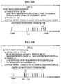
- Figs. 6A through 6E illustrate the wavelength control operation performed in the described network system of JP '092.
- a series of steps (1) to (5) of operation are performed by the optical transmitter 451 in each of the nodes 401 to 403.
- Each of the steps (1) to (5) is shown by means of a waveform chart illustrative of the wavelength disposition in which the abscissa indicates the wavelength, while vertical lines show wavelengths provided by the tunable LD 502. Wedge-form regions show the transmission bands of the tunable optical filter 503.
- Table 1 below outlines the operations of the tunable optical filter 503 and tunable LD 502 of the optical transmitter, as well the status of the optical switch 510, in each of steps (1) to (5).
- Step (1) in Fig. 6A shows the operation for detecting the wavelength disposition, performed immediately before the light emission from the optical node which has been instructed by the associated terminal station to transmit data.
- Sweeping of the transmissive wavelength of the tunable optical filter 503 is performed over the entire range of wavelength tuning, i.e., from the minimum wavelength ⁇ Fmin to the maximum wavelength ⁇ Fmax.
- the tunable LD 502 is kept off, while the optical switch 510 has been turned to select the optical confluence device 511.
- the wavelength control system 501 can grasp the disposition of all wavelengths present on the transmission line. It is therefore understood that the wavelength ⁇ a1 is the wavelength which is on the short-wavelength end of the wavelength disposition on the transmission line.
- Step (2) shown in Fig. 6B performs, subsequent to Step (1), setting of the wavelength to be transmitted from the tunable LD 502. More specifically, this step sets the wavelength of the tunable optical filter 503 to ⁇ Fs which is spaced by ⁇ from the above-mentioned wavelength ⁇ a1.
- the optical switch 501 remains in the same state as that in Step (1), i.e., it is connected to the optical confluence device 511. In this state, sweeping of the wavelength of the tunable LD 502 is performed, starting from the minimum wavelength ⁇ Lmin of the wavelength tunable range of the tunable LD 502. Sweeping ceases when the output of the discriminator 508 is turned to "H".
- the wavelength of the light emitted from the tunable LD 502 coincides with the set wavelength ⁇ Fs of the tunable optical filter 503, and is set to a wavelength position which is on the short-wavelength side of the adjacent wavelength ⁇ a1 and spaced therefrom by ⁇ which is the intended channel spacing.
- Step (3) shown in Fig. 6C performs, subsequent to Step (2), an operation for maintaining the wavelength spacing. Sweeping of the transmissive wavelength band of the tunable optical filter 503 is performed starting from ( ⁇ L - d ⁇ ) to ( ⁇ L + ⁇ + d ⁇ ) , where ⁇ L represents the luminescent wavelength of the tunable LD, while d ⁇ is a margin which is preserved to ensure detection of the wavelengths ⁇ L and ⁇ a1 when the channel spacing is held at ⁇ .
- the wavelength ⁇ L of the light from the tunable LD 502 is so controlled that the wavelength spacing between the wavelengths ⁇ a1 and ⁇ L as monitored through the sweeping of the wavelength of the tunable optical filter 503 is maintained equal to the above-mentioned channel spacing ⁇ . If the wavelength spacing is smaller than the channel spacing ⁇ , a control is performed to shift the transmission wavelength ⁇ L towards the shortest wavelength end, whereas, if the wavelength spacing is greater than the channel spacing ⁇ , a control is performed to shift the same towards the longest wavelength end, thus maintaining the wavelength spacing equal to the channel spacing ⁇ .
- the optical switch 510 is turned to select the transmission line, so that the light from the tunable LD 502 is delivered to the transmission line.
- Step (4) shown in Fig. 6D performs a wavelength shifting operation of the tunable LD 502 when the adjacent wavelength ⁇ a1 is extinguished in the preceding Step (3).
- the operations and states of the tunable optical filter 503, tunable LD 502, and the optical switch 510 are the same as those in Step (3).
- this step (4) repeatedly performs the detection of the wavelength disposition through the sweeping of the transmissive wavelength band of the tunable optical filter 503 from ( ⁇ L - d ⁇ ) to ( ⁇ L + ⁇ + d ⁇ ) and subsequent shifting of the transmission wavelength ⁇ L of the tunable LD 502 towards the long-wavelength end.
- Step (5) shown in Fig. 6E performs an operation for maintaining the wavelength spacing, after the repetition of the operation in Step (4). Sweeping of the transmissive wavelength band of the tunable optical filter 503 from ( ⁇ L - d ⁇ ) to ( ⁇ L + ⁇ + d ⁇ ) is performed to detect an adjacent wavelength ⁇ a2, and the shifting of the transmission wavelength ⁇ L of the tunable LD 502 is ceased when the adjacent wavelength ⁇ a2 is detected.
- the operation in Step (5) is the same as that in Step (3), except that the adjacent channel has been changed from ⁇ a1 to ⁇ a2.
- each sending terminal station performs sweeping to detect any transmission wavelength of another station which may exist on the transmission line, and performs transmission of data by setting its transmission wavelength to the shortest end of the tunable wavelength range. Then, if the transmission from another station which has been executed at a longer transmission wavelength is ceased, the above-mentioned sending station shifts its transmission wavelength to a longer wavelength. The same shifting operation is performed when the transmission from still another station which has been executed at a longer transmission wavelength is ceased.
- the transmitted data contains address data identifying the destination.
- the optical receiver of each station reads, via the light-receiving element, the header portion of the data while performing sweeping of its tunable optical filter at a predetermined time interval, and receives the data when the header portion of the data identifies this station as being the destination station.
- a wavelength multiplex communication network system in accordance with the first embodiment has a construction as shown in Fig. 4.
- Each of the optical nodes incorporated in the system has a construction shown by the block diagram in Fig. 5. The operation and function of the blocks are not described in order to eliminate duplication of explanation.
- Fig. 1 is a chart showing wavelength disposition illustrative of the wavelength control in accordance with the present invention. Wavelength is measured along the abscissa. Vertical lines indicate wavelengths of light signals from operating tunable LDs 502. Horizontal lines above these vertical lines show the continuous wavelength tunable ranges of the tunable LD 502 in the optical node which will be specifically mentioned in the following description of the wavelength control in accordance with the present invention. This optical node, therefore, will be referred to as the "subject optical node". In the illustrated case, there are three continuous wavelength tunable ranges #1, #2, and #3.
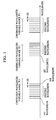
- Figs. 2A - 2D illustrate the operation of the first embodiment of the wavelength control method of the present invention.
- a process is executed for the purpose of setting the transmission wavelength of the tunable LD 502, including four steps (I) to (IV), shown in Figs. 2A-2D, respectively.
- steps (I) to (IV) have reference to Steps (1) and (2) of the operation performed in the network system of JP '092, described before in connection with Fig. 6. Steps I - IV are outlined in Table 2 below.
- Fig. 2A shows wavelength disposition on a wavelength multiplex transmission line, with the distance along the abscissa indicating spread of wavelength.
- Fig. 2A shows an enlarged part of Fig. 1; that is, only the continuous wavelength tunable ranges #1 and #2, among the three ranges #1 to #3 available on the tunable LD 502, are shown.
- Solid vertical lines show the existing wavelengths, while broken vertical lines show the candidate wavelengths.
- Wedge-shaped region ⁇ Fmax represents the longest transmissive wavelength of the tunable optical filter 503, while ⁇ Fmin represents the shortest transmissive wavelength of the same.
- tunable optical filter 503 and tunable LD 502 of the optical transmitter are also shown in each of the steps (I) to (IV) of Figs. 2A - 2D, respectively.
- the state of the optical switch 510 is not specifically shown in Figs. 2A - 2D, because the optical switch 510 constantly selects the optical confluence device 510 throughout the steps (I) to (IV).
- ⁇ indicates the channel spacing to be maintained under the wavelength control of the invention
- ⁇ Lmin indicates the shortest wavelength in the wavelength tunable range available on the tunable LD 502 of the optical transmitter in the subject optical node
- ⁇ L indicates the transmission wavelength under the control
- ⁇ Fmin and ⁇ Fmax respectively indicate the shortest and longest wavelengths of the wavelength tunable range of the tunable optical filter 503
- ⁇ Fs1, ⁇ Fs2 and ⁇ Fs3 respectively indicate the wavelengths of the tunable optical filter 503 as obtained in the course of setting of the wavelength of the tunable LD 502
- ⁇ a1, ⁇ a2, and ⁇ a3 respectively indicate adjacent wavelengths which are mentioned in the following description as being reference wavelengths from which the transmission wavelength to be obtained has to be spaced in order to avoid interference.
- the tunable LD 502 of the optical transmitter used in the present invention has a certain wavelength tunable range which contains a plurality of discrete continuous wavelength tunable ranges. Only three, i.e., #1, #2, and #3, of these discrete continuous wavelength tunable ranges are shown in Fig. 1.
- the wavelength control is performed so as to set the transmission wavelength of the tunable LD 502 such that the transmission wavelength coincides with one of the candidate wavelengths each of which is within any one of the continuous wavelength tunable ranges #1 to #3 and is spaced by the required channel spacing ⁇ from any existing wavelength which is on one end of any group of existing wavelengths (solid vertical lines) in the illustrated wavelength disposition. Referring to Fig.
- the characteristic of the tunable LD 502 in terms of the current injected into the LD and the wavelength of light emitted therefrom has not been stored in the wavelength control system 501 of the optical transmitter.
- the wavelength control system 501 detects the wavelength disposition of the existing wavelengths, through sweeping of the wavelength of the tunable optical filter 503, in order to find a wavelength which is within any one of the continuous wavelength tunable ranges and which is spaced by the required channel spacing ⁇ from any existing wavelength on one end of any group of existing wavelengths.
- Step (I) conducts detection of the wavelength disposition on the optical fiber transmission line of the network system.
- the transmissive wavelength range of the tunable optical filter 502 is swept from ⁇ Fmin to ⁇ Fmax, thereby detecting disposition of existing wavelengths.
- Wavelengths indicated by broken vertical lines are located as the candidates of the transmission wavelength to be set, based on the wavelength spacing described above.
- Step (II), shown in Fig. 2B, conducts first cycle of a wavelength setting operation for setting the wavelength of the tunable LD 502.
- the wavelength of the tunable optical filter 503 is set to the longest wavelength ⁇ Fs1 from among the candidate wavelengths, and the luminescent wavelength of the tunable LD 502 is swept from ⁇ Lmin to ⁇ Fs1.
- the wavelength Fs1 is between the continuous wavelength tunable range #1 and the continuous wavelength tunable range #2, so that the wavelength of the tunable LD 502 never coincides with the wavelength Fs1, despite the sweeping up to the wavelength ⁇ Lmax.
- the first cycle of operation for setting the wavelength of the tunable LD 502 fails to hit.
- Step (III) shown in Fig. 2C, performs a second cycle of the operation for setting the wavelength of the tunable LD 502.
- This operation is substantially the same as that in Step (II) except that the wavelength of the tunable optical filter 503 is set to the candidate wavelength ⁇ Fs2 which is second to the longest.
- the wavelength ⁇ Fs2 is between the continuous wavelength tunable range #1 and the continuous wavelength tunable range #2, so that the wavelength of the tunable LD 502 never coincides with the wavelength Fs2, despite the sweeping up to the wavelength ⁇ Lmax.
- the second cycle of the operation for setting the wavelength of the tunable LD 502 also fails to hit.
- Step (IV) performs a third cycle of the operation for setting the wavelength of the tunable LD 502.
- This operation is substantially the same as that in Step (II) except that the wavelength of the tunable optical filter 503 is set to the candidate wavelength ⁇ Fs3 which is third to the longest.
- the wavelength ⁇ Fs3 falls within the continuous wavelength tunable range #2. Therefore, when the wavelength of the light emitted from the tunable LD 502 coincides with ⁇ Fs3 during the sweeping of the wavelength of the tunable LD 502, the tunable optical filter 502 passes this light of the wavelength ⁇ Fs3 to the light-receiving element 506.
- the output from the light-receiving element 506 exceeds the threshold level of the discriminator 508, thus confirming that the wavelength of the light from the tunable LD 502 has coincided with the candidate wavelength ⁇ Fs3.
- the luminescent wavelength of the tunable LD 502, therefore, is set to ⁇ Ls3.
- the optical switch 510 is turned to select the transmission line, and an operation for maintaining the wavelength spacing from the adjacent wavelength is conducted in the same manner as that in the network system described before as a reference.
- the luminescent wavelength of the tunable LD 502 is set in the third cycle of the setting operation, this is only illustrative and the setting may be done in the first or second cycle, or fourth or further cycle, of the setting operation, depending on the wavelength disposition and the disposition of the continuous wavelength tunable ranges.
- the described embodiment of the present invention permits the use of a tunable LD having a wavelength tunable range which is as wide as several tens of nm, although this range contains discontinuities, thus making it possible to implement a wavelength division multiplexing communication network having a greater number of wavelength multiplexing.
- One advantage of the described embodiment is that the wavelength characteristic of the tunable LD 502 need not be adjusted when fabricating an optical transmitter or when replacing a tunable LD 502.
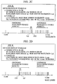
- Figs. 3A and 3B are illustrations of the operation of the second embodiment of the wavelength control method in accordance with the present invention. These Figures show steps which correspond to the steps of the first embodiment described before in connection with Figs. 2A - 2D. Thus, symbols appearing in this Figure represent the same things as those in Figs. 2A - 2D. More specifically, Figs. 3A and 3B show a series of Steps (i) and (ii) for setting the luminescent wavelength of the tunable LD.
- the wavelength control system 501 of the optical transmitter stores beforehand the relationship between the electrical current injected to the tunable LD 502 and the wavelength of the light emitted therefrom, as well as the relationship between the voltage applied to the tunable optical filter 503 and the wavelength selected by this filter. It is also to be understood that the second embodiment only requires determining in which one of the plurality of discrete continuous wavelength tunable ranges the wavelength which does not interfere with other wavelength is contained or, in which discrete continuous wavelength tunable ranges the wavelengths which do not interfere with other wavelength are contained. In this embodiment, therefore, any error on the order of ⁇ in the relationships between the wavelengths and the control variables is permissible.
- a wavelength is looked for which falls within any one of the continuous wavelength tunable ranges and which is spaced ⁇ from a wavelength which is on one end of a group of existing wavelengths, in a manner which will now be described with reference to Figs. 3A and 3B.
- Step (i) performs detection of the wavelength disposition. More specifically, the transmissive wavelength of the tunable optical filter 503 is swept over a range from ⁇ Fmin to ⁇ Fmax, whereby the disposition of existing wavelengths on the transmission line is detected. Then, candidate wavelengths for emission from the tunable LD 502 are searched for within the continuous wavelength tunable ranges, based on the transmissive wavelength characteristic of the tunable optical filter 503 and the luminescent wavelength characteristic of the tunable LD 502. As a result, the wavelength indicated by broken vertical line is determined as the set wavelength.
- Step (ii) shown in Fig. 3B executes an operation for setting the luminescent wavelength of the tunable LD 502.
- This operation is preceded by setting the transmissive wavelength of the tunable optical filter 503 to the above-mentioned set wavelength which is indicated by ⁇ Fs.
- the luminescent wavelength of the tunable LD 502 is swept starting from ⁇ Lmin2, until coincidence with the wavelength ⁇ Fs is obtained. Consequently, the tunable LD 502 is set to illuminate at the set wavelength which is on the short-wavelength side of the group of existing wavelengths and which is spaced by the required channel spacing ⁇ from the existing wavelength which is at the short-wavelength end of the group of existing wavelengths.
- the second embodiment of the present invention it is possible to set the luminescent wavelength of the tunable LD 502 only by one cycle of the wavelength setting operation, with the result that the time required for the wavelength setting operation is shortened, by virtue of the fact that the wavelength characteristics of the tunable LD 502 and the tunable optical filter 503 are stored in the wavelength control system 501.
- the first and second embodiments as described are not exclusive and may be modified provided that the luminescent wavelength of the tunable LD can be performed equally well.
- the wavelength control method of the present invention may be carried out in such a manner that each cycle of wavelength setting operation is necessarily preceded by the wavelength disposition detecting operation.
- optical transmitter as well as the constructions of other components of the system, also is illustrative.
- control of the luminescent wavelength of the tunable LD 502 may be performed by controlling the temperature of the semiconductor laser element of the tunable LD 502, instead of controlling the electrical current injected by an tunable LD driver circuit 504 as done in the described embodiments.
- a filter of a type other than Fabry-Perot resonator type as the tunable optical filter 503.
- the described external intensity modulation may be substituted by other suitable modulation method.
- a direct intensity modulation which directly modulates the tunable laser diode may be used, provided that no chirping takes place.
- FSK Frequency Shift Keying
- Direct polarization modulation method also can be adopted, using a device of the type described in Applied Physics Letters, Vol. 67, No. 23, 1995, "Polarization switching in AlGaAs/GaAs distributed feedback lasers between the stable single longitudinal modes".
- the embodiments and modifications described above employ such a system arrangement that the tunable optical filter serving as the detecting means for the purpose of wavelength control is provided in each of the optical nodes.
- the detecting means is not provided in individual optical nodes.
- a center node 701 is used in place of the star coupler incorporated in the preceding embodiments.
- Optical nodes 711, 712, ..., 71n, associated with terminal stations 721, 722, ..., 72n, respectively, are connected to the center node 701.
- the third embodiment has a common detecting means provided in the center node. The detecting means in the center node produces wavelength control information. Based on such wavelength control information, the wavelength control is performed through mutual communication between the center node and each optical node.
- the third embodiment conducts wavelength multiplexing of two types of communication: (1) the wavelength division multiplexing communication of the type performed in each of the preceding embodiments, and (2) the communication for exchanging the wavelength control information between the optical nodes and the center node.
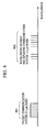
- Fig. 8 illustrates wavelength disposition under such wavelength division multiplexing of the two types of communication.
- a group of wavelengths collectively denoted by 802 corresponds to the wavelength division multiplexing communication of the type performed in the preceding embodiments.
- a high-density wavelength division multiplexing is conducted by using 1.5 ⁇ m band.
- 801 denotes a wavelength region for packet communication of the wavelength control information.
- a 1.3 ⁇ m-wave band is allocated for this purpose.
- This wavelength region for packet communication is commonly used by all the optical nodes, for the purpose of mutual communication between the optical nodes and the center node, executed by using a known technique such as CSMA/CD.
- the wavelength control means in the center node and the optical nodes connected to the center node have means which enable packet communication between the center node and the optical nodes.
- Fig. 9 shows the construction of the center node 701.
- detecting means used for the purpose of wavelength control is provided in the center node.
- the detection of wavelength is performed in the center node and is transmitted from there to each optical node.
- Numeral 901 denotes a wavelength division multiplexing communication control system for processing the wavelength control information.
- Numerals 902 and 903 respectively denote an optical transmitter and an optical receiver which transmits and receives signals in the packet communication system.
- Numeral 904 denotes a wavelength detection system for detecting the wavelength disposition in the wavelength division multiplexing communication system.
- An optical branching device 905 is operative to separate the wavelength of the light signal of the wavelength multiplex communication control system and the wavelength of the light in the packet communication system from each other, and to deliver the light of the wavelength multiplex communication control system and the light of the packet communication system to the wavelength disposition detecting system 904 and the optical receiver 903, respectively.
- Numerals 906 and 907 denote input ports to which are connected the optical nodes through the transmission line, while 908 and 909 denote output ports to which also are connected to the optical nodes through the transmission line.
- the light inputted from one of the input ports is distributed to the output ports through a optical-coupler 910 having (N + 1) input terminals and (N + 1) output terminals.
- Numerals 911 and 912 denote optical switches, each being capable of selecting one of two states: namely, a state in which it passes the light from the input port to the optical-coupler 910 so as to allow the light to be distributed to the output ports, and a state in which it blocks the input light so as to prohibit the distribution of the light to the output ports.
- the optical switch used in this embodiment is of a light-path change-over type and is operative in such a manner that, when it does not pass the input light to the optical-coupler 910, it delivers the light to the optical-coupler 913, whereas, when it does not pass the input light to the optical-coupler 913, it delivers the light to the optical-coupler 910.
- the light input through the optical-coupler 913, optical-coupler 914, and the optical branching device 905 is led to the wavelength disposition detecting system 904 or the optical receiver 903.
- the optical switch used in this embodiment is of the light-path change-over type. Therefore, in order that the output from the optical switch is received also by the wavelength disposition detecting system even when the same output is being led to the optical-coupler 910, one of the outputs of the optical-coupler 910 is led to the optical branching device 905 via the optical-coupler 914. Furthermore, the output from the optical transmitter 902 is led to one of the input terminals of the optical-coupler 910 so that it can reach the optical node.
- the third embodiment is basically the same as the preceding embodiments insofar as it performs the wavelength control based on the result of detection of the wavelength of light emission from the optical node.
- the third embodiment is different from the preceding embodiments in that the mutual exchange of the wavelength control information is conducted through the packet communication system. More specifically, when an optical node demands signal transmission, such a transmission demand is sent to the wavelength division multiplexing communication control system 901 of the center node. In response to the transmission demand, the wavelength disposition detecting system 904 of the wavelength division multiplexing communication control system 901 performs the wavelength detecting operation, so as to find a wavelength which does not interfere with other wavelengths.
- the detecting means of the wavelength disposition detecting means is set to be able to detect light of a wavelength which falls with any one of the continuous wavelength tunable ranges and which does not interfere with other wavelengths.
- the wavelength multiplex communication control system 901 then delivers to the optical node demanding the transmission an instruction to perform sweeping of the wavelength of the optical node.
- a control is performed to preserve the predetermined spacing from the adjacent wavelength, as in the second embodiment. Namely, when the spacing from the adjacent wavelength has become too small, an instruction for shifting the luminescent wavelength in a direction to increase the spacing is given through the packet communication system.
- the wavelength control may be executed in the same way as that in the first embodiment.
- the present invention it is possible to increase the degree of wavelength multiplexing in a wavelength division multiplexing communication network, by making a full use of overall discontinuous wavelength tunable range of a tunable LD in which a plurality of discrete continuous wavelength tunable ranges exist. This means that the communication efficiency can markedly improve using a tunable LD having an overall wavelength tunable range which is wide but includes discontinuities.
- the luminescent wavelength of the tunable LD is set to one of the candidate wavelengths which are adjacent to existing wavelengths on the transmission line, through setting of the transmissive wavelength of a tunable optical filter to successive one of the candidate wavelengths. It is therefore possible to densely arrange a plurality of transmission channels, while preserving the required channel spacing ⁇ between the adjacent channels, with an inexpensive arrangement which does not require any storage means for storing information to be used in the wavelength control system.
- a candidate wavelength to which the luminescent wavelength of the optical transmitter is to be set can be detected quickly, so setting of the luminescent wavelength to such a wavelength can be achieved quickly, thus enabling faster data communication.
- a method of controlling a wavelength of emitted light in a network system having a light transmission line for transmitting light, light-emitting means having a plurality of discrete continuous-wavelength-tunable ranges and emitting the light to the light transmission line, and detecting means for detecting light on the light transmission line includes detecting, by the detecting means, a wavelength falling within one of the plurality of continuous-wavelength-tunable ranges of the light-emitting means which does not interfere with any wavelengths of light being transmitted on the light transmission line, and emitting, to the light transmission line, light from the light-emitting means at the wavelength detected in said detecting step.
Abstract
Description
- The present invention relates to a method of controlling wavelength used in wavelength multiplex communication networks and also to a network system using the wavelength controlling method.
- In general, a wavelength multiplex communication network system employs a multiplicity of independent channels arranged in a single transmission line such that each channel performs communication independently of other channels. Such a wavelength multiplex communication network system does not necessitate frame synchronization or other multiplexing processing along the time axis and, hence, does not require coincidence of transmission rates of different channels. This type of communication network system, therefore, is suitable for use in multi-media communications in which flexibility or adaptability of the network is an important requisite.
- A wavelength multiplex communication network system has, for example, a number of terminal stations, each having a combination of a wavelength tunable optical transmitter and receiver. In operation, the transmitting terminal station controls the wavelength tunable optical transmitter such that the transmitter transmits light of a wavelength which is not being used on the network communication transmission line, while the receiving station controls a tunable optical filter of the optical receiver such that the central wavelength of the spectrum passed by the filter coincides with the wavelength of the light to be received. Thus, the range of wavelength which can be used in the wavelength multiplex communication network system is governed by the ranges over which the wavelengths of the optical transmitter and receiver are variable. Meanwhile, the wavelength spacing of the channels (referred to as "channel spacing", hereinafter) is determined by the width of the spectrum transmitted through the optical filter of the optical receiver.
- A semiconductor laser (referred to as "LD", hereinafter) of the wavelength tunable type can be used as the wavelength tunable light source. Research in recent years has been aimed towards widening the range of wavelength variation. At present, LDs of the multi-electrode DBR (Distributed Bragg Reflector) type and the multi-electrode DFB (Distributed Feedback) type have been put to practical use. These LDs have wavelength tunable ranges on the order of several nanometers (nm). An example of such multi-electrode LD is shown in TRI-ELECTRODE RESONATOR λ/4 SHIFT MQW-DFB LASER, Technical Report of the Institute of Electronics, Information and Communication Engineers, OQE (Optical and Quantum Electronics), 89-116. The tunable optical filter may also be a Fabry-Perot resonator-type filter. This type of filter, which has been put to practical use, has a wavelength tunable range of several tens of nm and a spectral width of 0.1 nm. An example of this type of filter is shown in "A field-worthy, high-performance, tunable fiber Fabry-Perot filter" preprint, ECOC (European Conference on Optical Communication) '90-605.
- The number of channels in a wavelength multiplex communication network system having a given range of wavelength variation can be increased by reducing the channel spacing. In order to reduce the channel spacing to a value which is not greater than the width of fluctuation caused by drifting of wavelengths of the tunable LD and tunable optical filter, it is necessary that the influence of drift is suppressed by a suitable control. To this end, it is necessary to stabilize the wavelength both absolutely and relatively. However, it is not easy to obtain an absolute reference for wavelength. Relative wavelength stabilization is also difficult to achieve, particularly in a communication network such as a LAN in which optical transmitters are located at remote places.
- The state of the art is such that the continuous wavelength tunable range afforded by tunable optical filters is greater than that of tunable LDs. For instance, while the continuous wavelength tunable range of a typical tunable LD is on the order of several nm, the range over which the wavelength transmissible through the tunable optical filter well exceeds 10 nm. Therefore, in a system in which tunable LD is used as light-emitting means while a tunable optical filter is used as detecting means, the continuous wavelength tunable range of tunable LD is one factor limiting the number of the channels.
- It has been known that there is a type of light-emitting means which can materially expand the range of wavelength variation of the emitted light, on condition that discontinuities of wavelength are allowed to be present in the wavelength tunable range. For instance, a certain type of tunable LD can exhibit an expanded wavelength tunable range of 10 nm or greater when discontinuities of wavelength are permitted. An example of such tunable LD is disclosed in IEEE Photonics Technology Letters, "A Three-Electrode Distributed Bragg Reflector Laser With 22 nm Wavelength Tuning Range," Vol. 3, No. 4, pp 299 - 301, (1991). More specifically, this LD is a three-electrode DBR-LD which has a gain-current supply electrode, a phase-current supply electrode and a Bragg-current supply electrode. It is reported that an expanded range of luminescent wavelength spanning about 22 nm between 1512 nm and 1534 nm, when the current supplied to the Bragg electrode is varied between - 120 mA and + 120 mA, while the gain-current supply electrode is supplied with a constant current of 175 mA. It is also reported that there are about 20 discontinuities within the above-mentioned expanded range.
- An object of the present invention is to provide a wavelength controlling method in which the number of channels is not limited by the width of a single continuous variable range of wavelength of emitted light.
- The present invention provides a wavelength controlling method which enables the use of advantages of light emitting means, such as the means described above, having a plurality of discrete continuous wavelength tunable ranges.
- According to one aspect of the present invention, there is provided an emission light wavelength controlling method for use in a network system having a light transmission line for transmitting light, a light-emitting device having a number of discrete continuous-wavelength-tunable ranges and outputting light to the light transmission line, and a detector for detecting light on the light transmission line. The method includes a step of detecting, using the detecting means, a wavelength which falls within any one of the continuous-wavelength-tunable ranges of the light-emitting device and which does not interfere with any other light when delivered by the light-emitting device to the light transmission line. The method also includes a step of delivering, to the light transmission line, the output light from the light-emitting device at the wavelength which falls within one of the continuous-wavelength-tunable ranges of the light-emitting device and which does not interfere with other light.
- According to this controlling method, it is possible to control the wavelength of light emitted from a light-emitting device having a plurality of discrete continuous wavelength tunable ranges, without the risk of interference with other light.
- The step of detecting the wavelength which falls within any one of the continuous-wavelength-tunable ranges of the light-emitting device and which does not interfere with other light may include: a first sub-step of detecting, using the detecting means, a wavelength which does not interfere with other light; a second sub-step of controlling the detecting means such that the detecting means can detect light of the detected wavelength which does not interfere with other light; and a third sub-step of varying the wavelength of the output light from the light-emitting device and discriminating whether or not the detecting means detects the output light from the light-emitting device. Executing such sub-steps enables detection of a wavelength which falls within one of the continuous-wavelength-tunable ranges of the light-emitting device and which does not interfere with other light, even when the wavelength tunable range of the light-emitting device is unknown. When there are a number of wavelengths which do not interfere with other the other light, while the detecting means fails to detect the output light from the light-emitting device despite execution of the second and third sub-steps, the method may be carried out by repeating the second and third sub-steps. In such a situation, the second sub-step controls the detecting means to enable the detecting means to detect another wavelength from among the wavelengths which do not interfere with the other light. This second sub-step is followed by the third sub-step. The second and third sub-steps are repeated until the detecting means detects the output light from the light-emitting device.
- On the other hand, when the wavelength tunable range of the light-emitting device is known, the step of detecting the wavelength which falls within one of the continuous-wavelength-tunable ranges of the light-emitting device and which does not interfere with other light may be carried out by executing a sub-step of detecting, using the detecting means, a wavelength which does not interfere with other light, and a sub-step of discriminating whether or not the detected wavelength falls within one of the continuous-wavelength-tunable ranges of the light-emitting means which have been stored.
- The method may further include a step of controlling, after the execution of the delivering step, the wavelength of the output light so that the wavelength is spaced a predetermined amount from an adjacent wavelength or is maintained at an end of the continuous-wavelength-tunable range.
- Various methods are available for preserving predetermined spacing between the adjacent wavelengths. For instance, the predetermined spacing may be preserved by a process including controlling the detecting means to vary the wavelength detectable by the detecting means, by changing the value of a parameter which determines the detectable wavelength. The process also includes detecting, by the detecting means thus controlled, both the wavelength of the output light from the light-emitting means and the above-mentioned adjacent wavelength. In addition, the process includes comparing the values of the parameter with which the wavelength of the output light and the wavelength of the adjacent wavelength were detected, thereby detecting the difference between the parameter values. The parameter may be, for instance, a voltage or current for controlling a tunable optical filter for varying the wavelength selectable by the tunable optical filter when such a filter is used as the detecting means. The process also includes controlling the light-emitting means to increase the spacing between the wavelength of the output light and the adjacent wavelength when the difference in the parameter value is small, and to decrease the spacing when the difference in the parameter value is large. It is to be noted, however, the relationship between the parameter value and the detectable wavelength is not always linear. The process, therefore, may be carried out while effecting any necessary compensation for each of the wavelength ranges to be detected.
- Another way of preserving the predetermined spacing between the wavelengths employs first and second detecting means which are in fixed wavelength relationship with each other. The first detecting means is adapted to detect the wavelength of the output light from the light-emitting means, while the second detecting means detects the adjacent wavelength. Then, while the second detecting means is detecting the adjacent wavelength, a servo control is performed to vary the wavelength of the output light from the light-emitting means until the wavelength of the output light is detected by the first detecting means. In this way, the required spacing is preserved between the wavelength of the output light and the adjacent wavelength.
- The method also may be carried out such that the delivery of the output light from the light-emitting means to the transmitting line is prohibited until the wavelength of the output light is set not to interfere with the other light. Alternatively, the method may be carried out such that the delivery of the output light from the light-emitting means to part of the transmitting line is prohibited until the wavelength of the output light is set not to interfere with the other light. Thus, the delivery of the output light is controlled to avoid any interference which otherwise may be caused by delivering light of a wavelength which risks interference. A device controllable to selectively deliver output light or, alternatively, a device which performs change-over of a light path, may be used as the means for selectively delivering the output light to the transmission line or as the means for delivering the output light only to a selected portion of the transmission line. Both types of device are known and available as optical switches.
- When the network system has a portion in which interference is permissible, the method of the invention does not exclude delivery to such a portion of output light which has not been controlled to avoid interference with any other light. For instance, the arrangement may be such that the light-emitting means is provided in an optical node which also accommodates the detecting means and output control means for selectively delivering the output light of the light-emitting means to the transmission line. With this arrangement, the output light from the light-emitting means is delivered to the detecting means and is controlled to a wavelength which does not interfere with any other light, before the output light is actually delivered to any portion of the transmission line through the optical node.
- The situation, however, is different when the network has a star-type arrangement, in particular when the light-emitting means and the light detecting means are far away from each other and communicable only through the transmission line which is inherently intended for communication, i.e., when there is no other separate line between the light emitting and receiving means. Thus, the light from the light-emitting means reaches the detecting means along the transmission line which is intended for use in communication. An advisable arrangement for such case involves disposing a device, such as an optical switch, in the star coupler of the star connection. The optical switch permits light from the light-emitting means to reach the detecting means but not to reach other output ports which are connected to other light-emitting means and other light-receiving means, while performing control to set the output light to a wavelength which does not interfere with any other light. The portion of the transmission line between the light-emitting means and the star coupler is a portion which permits interference. Thus, the delivery of the output light to that portion of the transmitting line does not matter, even if the wavelength of the output light potentially risks interference with other light.
- The network system in accordance with the present invention may be constructed such that the transmission line has a number of transmission sub-lines which are coupled through a optical-coupler. The optical-coupler has at least one input port and a number of output ports to which the light inputted from the input port is passed. Practically, a star coupler can suitably be used as the optical-coupler.
-
- Fig. 1 is an illustration of wavelength disposition along a transmission line under a wavelength control method of the present invention;
- Figs. 2A through 2D are illustrations of the operation of a first embodiment of the wavelength controlling method in accordance with the present invention;
- Figs. 3A and 3B are illustrations of the operation of a second embodiment of the wavelength controlling method in accordance with the present invention;
- Fig. 4 is an illustration of the construction of a WDM network system;
- Fig. 5 is an illustration of the construction of an optical transmitter incorporated in an optical node of the WDM network system;
- Figs. 6A through 6E are illustrations of operation of a wavelength controlling method, shown by way of reference example;
- Fig. 7 is an illustration of operation of a second embodiment of the wavelength controlling method in accordance with a third embodiment of the present invention;
- Fig. 8 is an illustration of wavelength disposition in accordance with the third embodiment, shown by way of example;
and - Fig. 9 is an illustration of the construction of a center node incorporated in the third embodiment of the present invention.
- Before turning to the detailed description of the invention, a reference is made to a wavelength controlling method based on a technique disclosed in a co-pending Japanese Patent Application No. 8-163092 (JP '092) filed by the same applicant in order to facilitate understanding of the present invention. According to this method shown in JP '092, when transmissions are performed by a plurality of optical transmitters, the wavelengths of the light outputs from the optical transmitters are disposed at a predetermined spacing from the longer-wavelength end towards the shorter-wavelength end or vice versa, in accordance with the order of the timing of commencement of the transmission. This method therefore does not require any absolute wavelength reference. Spacing between each channel and adjacent channels is maintained based on the result of sweeping of wavelength region around the wavelength of each optical transmitter performed by a tunable optical filter.
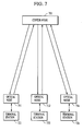
- Fig. 4 illustrates an example of wavelength-division-multiplexing (WDM) communication network system incorporating an optical transmitter which is controlled in accordance with the above-described wavelength controlling method of JP '092. This system has a star-type network topology. As will be seen from this Figure, the WDM communication network system has
optical nodes terminal stations star coupler 420, andoptical fibers optical node optical transmitter 451, anoptical receiver 452, and an optical branchingdevice 453. To simplify the drawing figure, the components of the optical nodes are only illustrated fornode 401. Moreover, although the arrangement for only three terminal stations is shown for the purpose of simplification of illustration, several tens of terminal stations are actually connectable in this network system. - The
terminal stations optical nodes optical node 401 is connected to thestar coupler 420 both through a transmittingoptical fiber 431 and anoptical fiber 441 through which thenode 401 receives light. Similarly, theoptical nodes star coupler 420 via transmitting and receivingoptical fibers optical transmitters 451 are sent to thestar coupler 420 via theoptical fibers optical transmitter 451 to all theoptical nodes optical fibers device 453 into two parts which are delivered respectively to theoptical transmitter 451 and theoptical receiver 452. As a consequence, the tunable optical filters of the optical transmitter and the optical receiver of each terminal station receive the light transmitted from its respective terminal station, together with the light signals transmitted from other terminal stations. - Referring to Fig. 5, the optical transmitter has a
wavelength control system 501, atunable LD 502, a tunableoptical filter 503, a tunableLD driver circuit 504, a tunable opticalfilter driver circuit 505, a light-receivingelement 506, anamplifier 507, adiscriminator 508, anoptical modulator 509, anoptical switch 510 and anoptical confluence device 511. - The
wavelength control system 501 controls the tunableLD driver circuit 504 and the tunable opticalfilter driver circuit 505 based on a signal outputted from thediscriminator 508, thereby performing the control of the wavelength. Operations including starting of the wavelength control are controlled from the terminal station which is connected to thewavelength control system 501. The wavelength control system includes, for example, an arithmetic processing circuit, storage device, an A/D converter, a D/A converter, and so forth. The storage device stores parameters which are used in the wavelength controlling operation, as well as operation sequence program. - The
tunable LD 502 may be a DBR-type LD, while a Fabry-Perot tunable optical filter may be used as the tunableoptical filter 503. The half amplitude width of the transmissive spectrum of the tunableoptical filter 503 is a main factor which determines the channel spacing Δλ. The half amplitude width, therefore, should be determined to be a suitable value which is not greater than the channel spacing Δλ. The wavelength tunable range of the tunableoptical filter 503 is greater than the wavelength tunable range of anytunable LD 502 in the network. - The
optical modulator 509 performs intensity modulation of the output light from thetunable LD 502 with the transmitted signal. When the modulation is conducted directly with the current injected into thetunable LD 502, chirp over 0.1 nm or so inevitably takes place. Therefore, the described method employs an external intensity modulation system by optical modulator. - The tunable
LD driver circuit 504 drives thetunable LD 502, i.e., injects current into thetunable LD 502, such that the wavelength of light emitted from thetunable LD 502 coincides with the wavelength corresponding to the tunable LD control voltage (referred to as VL, hereinafter) derived from thewavelength control system 501. - The tunable optical
filter driver circuit 505 drives the tunableoptical filter 503 such that the wavelength of transmitted through the tunableoptical filter 503 coincides with the wavelength corresponding to the tunable optical filter control voltage (referred to as VF, hereinafter) derived from thewavelength control system 501. - The
discriminator 508 has a threshold value which is not greater than the output of theamplifier 507 as obtained when the wavelength of light of each channel coming into the tunableoptical filter 503 from the transmission line coincides with the wavelength transmissive through the tunableoptical filter 503. For instance, the threshold value is set to the level of the half amplitude of the output from theamplifier 507. Thediscriminator 508 produces a signal H (digital signal "1") when the level of the input signal is not smaller than the threshold value, otherwise it produces a signal L (digital signal "0"). - The
optical transmitter 451 associated with each terminal station receives, as a result of the sweeping of the tunableoptical filter 503, wavelength-multiplexed light signal including the signal of the wavelength of the associated terminal station, through the receiving optical fiber 441 (or 442 or 443). The optical transmitter then detects the wavelength disposition in the multiplexed light signal and performs the wavelength control operation based on the detected wavelength disposition. - Figs. 6A through 6E illustrate the wavelength control operation performed in the described network system of JP '092. A series of steps (1) to (5) of operation are performed by the
optical transmitter 451 in each of thenodes 401 to 403. Each of the steps (1) to (5) is shown by means of a waveform chart illustrative of the wavelength disposition in which the abscissa indicates the wavelength, while vertical lines show wavelengths provided by thetunable LD 502. Wedge-form regions show the transmission bands of the tunableoptical filter 503. - Table 1 below outlines the operations of the tunable
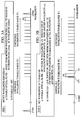
optical filter 503 andtunable LD 502 of the optical transmitter, as well the status of theoptical switch 510, in each of steps (1) to (5). - Detect wavelength disposition
- a) Tunable optical filter: Sweep from minimum wavelength end (λFmin) to maximum wavelength end (λFmax) of wavelength range
- b) Tunable LD: Off
- c) Optical switch: Turned to select optical confluence device
- Set wavelength of tunable LD
- a) Tunable optical filter: Set filter to wavelength λFs which is one of wavelength points spaced Δλ from another wavelength λa1.
- b) Tunable LD: LD is turned on. Sweep from minimum wavelength λLmin till wavelength accords with λFs.
- c) Optical switch: Turned to select optical confluence device.
- Deliver light to transmission line, while maintaining constant wavelength spacing from adjacent wavelength
- a) Tunable optical filter: Sweep from

- b) Tunable optical filter: Maintain wavelength spacing Δλ from adjacent wavelength λa1.
- c) Optical switch: Turned to select transmission line.
- Shift wavelength to longer side, since wavelength spacing has been increased due to extinction of adjacent wavelength
- a) Tunable optical filter: Sweep from

- b) Tunable LD: Maintain wavelength spacing Δλ from adjacent wavelength λa1.
- c) Optical switch: Turned to select tansmission line.
- Set wavelength of tunable LD.
- a) Tunable optical filter: Sweep from

- b) Tunable LD: Maintain wavelength spacing Δλ from adjacent wavelength λa2.
- c) Optical switch: Turned to select transmission line.
- More specifically, Step (1) in Fig. 6A shows the operation for detecting the wavelength disposition, performed immediately before the light emission from the optical node which has been instructed by the associated terminal station to transmit data. Sweeping of the transmissive wavelength of the tunable
optical filter 503 is performed over the entire range of wavelength tuning, i.e., from the minimum wavelength λFmin to the maximum wavelength λFmax. Meanwhile, thetunable LD 502 is kept off, while theoptical switch 510 has been turned to select theoptical confluence device 511. As a result of the sweeping, thewavelength control system 501 can grasp the disposition of all wavelengths present on the transmission line. It is therefore understood that the wavelength λa1 is the wavelength which is on the short-wavelength end of the wavelength disposition on the transmission line. - Step (2) shown in Fig. 6B performs, subsequent to Step (1), setting of the wavelength to be transmitted from the
tunable LD 502. More specifically, this step sets the wavelength of the tunableoptical filter 503 to λFs which is spaced by λΔ from the above-mentioned wavelength λa1. Theoptical switch 501 remains in the same state as that in Step (1), i.e., it is connected to theoptical confluence device 511. In this state, sweeping of the wavelength of thetunable LD 502 is performed, starting from the minimum wavelength λLmin of the wavelength tunable range of thetunable LD 502. Sweeping ceases when the output of thediscriminator 508 is turned to "H". Consequently, the wavelength of the light emitted from thetunable LD 502 coincides with the set wavelength λFs of the tunableoptical filter 503, and is set to a wavelength position which is on the short-wavelength side of the adjacent wavelength λa1 and spaced therefrom by Δλ which is the intended channel spacing. - Step (3) shown in Fig. 6C performs, subsequent to Step (2), an operation for maintaining the wavelength spacing. Sweeping of the transmissive wavelength band of the tunable
optical filter 503 is performed starting from
tunable LD 502 is so controlled that the wavelength spacing between the wavelengths λa1 and λL as monitored through the sweeping of the wavelength of the tunableoptical filter 503 is maintained equal to the above-mentioned channel spacing Δλ. If the wavelength spacing is smaller than the channel spacing Δλ, a control is performed to shift the transmission wavelength λL towards the shortest wavelength end, whereas, if the wavelength spacing is greater than the channel spacing Δλ, a control is performed to shift the same towards the longest wavelength end, thus maintaining the wavelength spacing equal to the channel spacing Δλ. When the wavelength of thetunable LD 502 is set to λFs, theoptical switch 510 is turned to select the transmission line, so that the light from thetunable LD 502 is delivered to the transmission line. - Step (4) shown in Fig. 6D performs a wavelength shifting operation of the
tunable LD 502 when the adjacent wavelength λa1 is extinguished in the preceding Step (3). The operations and states of the tunableoptical filter 503,tunable LD 502, and theoptical switch 510 are the same as those in Step (3). Thus, this step (4) repeatedly performs the detection of the wavelength disposition through the sweeping of the transmissive wavelength band of the tunableoptical filter 503 from
tunable LD 502 towards the long-wavelength end. - Step (5) shown in Fig. 6E performs an operation for maintaining the wavelength spacing, after the repetition of the operation in Step (4). Sweeping of the transmissive wavelength band of the tunable
optical filter 503 from
tunable LD 502 is ceased when the adjacent wavelength λa2 is detected. Thus, the operation in Step (5) is the same as that in Step (3), except that the adjacent channel has been changed from λa1 to λa2. - As will be seen from the foregoing description, in the network system shown as a reference example, each sending terminal station performs sweeping to detect any transmission wavelength of another station which may exist on the transmission line, and performs transmission of data by setting its transmission wavelength to the shortest end of the tunable wavelength range. Then, if the transmission from another station which has been executed at a longer transmission wavelength is ceased, the above-mentioned sending station shifts its transmission wavelength to a longer wavelength. The same shifting operation is performed when the transmission from still another station which has been executed at a longer transmission wavelength is ceased. The transmitted data contains address data identifying the destination. The optical receiver of each station reads, via the light-receiving element, the header portion of the data while performing sweeping of its tunable optical filter at a predetermined time interval, and receives the data when the header portion of the data identifies this station as being the destination station.
- Description will now be given of embodiments of the present invention. It is to be noted that features of the embodiments which are the same or equivalent to those in the foregoing description may not be fully described again in the following.
- A first embodiment of the present invention will be described with reference to the drawings. A wavelength multiplex communication network system in accordance with the first embodiment has a construction as shown in Fig. 4. Each of the optical nodes incorporated in the system has a construction shown by the block diagram in Fig. 5. The operation and function of the blocks are not described in order to eliminate duplication of explanation.
- Fig. 1 is a chart showing wavelength disposition illustrative of the wavelength control in accordance with the present invention. Wavelength is measured along the abscissa. Vertical lines indicate wavelengths of light signals from operating
tunable LDs 502. Horizontal lines above these vertical lines show the continuous wavelength tunable ranges of thetunable LD 502 in the optical node which will be specifically mentioned in the following description of the wavelength control in accordance with the present invention. This optical node, therefore, will be referred to as the "subject optical node". In the illustrated case, there are three continuous wavelength tunable ranges #1, #2, and #3. There are two types of vertical lines: solid vertical lines indicative of the wavelengths which have been excited and present on the transmission line in advance of the start of light emission from the subject optical node, referred to as "existing wavelengths"; and broken vertical lines indicative of candidate set wavelengths to which the transmission wavelength from the subject optical node can be set in accordance with the wavelength control method of the present invention. - Figs. 2A - 2D illustrate the operation of the first embodiment of the wavelength control method of the present invention. Before the optical transmitter associated with the subject optical node is commenced, a process is executed for the purpose of setting the transmission wavelength of the
tunable LD 502, including four steps (I) to (IV), shown in Figs. 2A-2D, respectively. These steps (I) to (IV) have reference to Steps (1) and (2) of the operation performed in the network system of JP '092, described before in connection with Fig. 6. Steps I - IV are outlined in Table 2 below. - Detect wavelength disposition
- a) Tunable optical filter: Sweep from minimum wavelength end λFmin to maximum wavelength end λFmax of wavelength range.
- b) Tunable LD: off
- Set wavelength of tunable LD
- a) Tunable optical filter: Set filter to wavelength λFs1 which is one of wavelength points spaced Δλ from another wavelength λa1.
- b) Tunable LD: LD is turned on. Sweep from minimum wavelength λLmin till wavelength accords with λFs1 or till λLmax is reached.
- Set wavelength of tunable LD
- a) Tunable optical filter: Set filter to wavelength λFs2 which is one of wavelength points spaced Δλ from another wavelength λa2.
- b) Tunable LD: LD is turned on. Sweep from minimum wavelength λLmin till wavelength accords with λFs2 or till λLmax is reached.
- Set wavelength of tunable LD
- a) Tunable optical filter: Set filter to wavelength λFs3 which is one of wavelength points spaced Δλ from another wavelength λa3.
- b) Tunable LD: LD is turned on. Sweep from minimum wavelength λLmin till wavelength accords with λFs3 or till λLmax is reached.
- Fig. 2A shows wavelength disposition on a wavelength multiplex transmission line, with the distance along the abscissa indicating spread of wavelength. For the purpose of simplification of the drawings, Fig. 2A shows an enlarged part of Fig. 1; that is, only the continuous wavelength tunable ranges #1 and #2, among the three
ranges # 1 to #3 available on thetunable LD 502, are shown. Solid vertical lines show the existing wavelengths, while broken vertical lines show the candidate wavelengths. Wedge-shaped region λFmax represents the longest transmissive wavelength of the tunableoptical filter 503, while λFmin represents the shortest transmissive wavelength of the same. Also shown are the operations or states of the tunableoptical filter 503 andtunable LD 502 of the optical transmitter in each of the steps (I) to (IV) of Figs. 2A - 2D, respectively. The state of theoptical switch 510 is not specifically shown in Figs. 2A - 2D, because theoptical switch 510 constantly selects theoptical confluence device 510 throughout the steps (I) to (IV). - In Figs. 2A - 2D, Δλ indicates the channel spacing to be maintained under the wavelength control of the invention, λLmin indicates the shortest wavelength in the wavelength tunable range available on the
tunable LD 502 of the optical transmitter in the subject optical node, λL indicates the transmission wavelength under the control, λFmin and λFmax respectively indicate the shortest and longest wavelengths of the wavelength tunable range of the tunableoptical filter 503, λFs1, λFs2 and λFs3 respectively indicate the wavelengths of the tunableoptical filter 503 as obtained in the course of setting of the wavelength of thetunable LD 502, and λa1, λa2, and λa3 respectively indicate adjacent wavelengths which are mentioned in the following description as being reference wavelengths from which the transmission wavelength to be obtained has to be spaced in order to avoid interference. - The
tunable LD 502 of the optical transmitter used in the present invention has a certain wavelength tunable range which contains a plurality of discrete continuous wavelength tunable ranges. Only three, i.e., #1, #2, and #3, of these discrete continuous wavelength tunable ranges are shown in Fig. 1. According to the present invention, the wavelength control is performed so as to set the transmission wavelength of thetunable LD 502 such that the transmission wavelength coincides with one of the candidate wavelengths each of which is within any one of the continuous wavelength tunable ranges #1 to #3 and is spaced by the required channel spacing Δλ from any existing wavelength which is on one end of any group of existing wavelengths (solid vertical lines) in the illustrated wavelength disposition. Referring to Fig. 1, there is no such candidate wavelength in the continuous wavelengthtunable range # 1. The single broken vertical line in therange # 2 and a couple of broken vertical lines in therange # 3 are the candidate wavelengths. The transmission of the light from thetunable LD 502 is conducted at a wavelength which coincides with one of these candidate wavelengths. The operation for setting the transmission wavelength will be more fully described with reference to Figs. 2A - 2D. - It is assumed here that, in this embodiment, the characteristic of the
tunable LD 502 in terms of the current injected into the LD and the wavelength of light emitted therefrom has not been stored in thewavelength control system 501 of the optical transmitter. Thewavelength control system 501 detects the wavelength disposition of the existing wavelengths, through sweeping of the wavelength of the tunableoptical filter 503, in order to find a wavelength which is within any one of the continuous wavelength tunable ranges and which is spaced by the required channel spacing Δλ from any existing wavelength on one end of any group of existing wavelengths. - Referring to Fig. 2A, Step (I) conducts detection of the wavelength disposition on the optical fiber transmission line of the network system. The transmissive wavelength range of the tunable
optical filter 502 is swept from λFmin to λFmax, thereby detecting disposition of existing wavelengths. Wavelengths indicated by broken vertical lines are located as the candidates of the transmission wavelength to be set, based on the wavelength spacing described above. - Subsequently, Step (II), shown in Fig. 2B, conducts first cycle of a wavelength setting operation for setting the wavelength of the
tunable LD 502. In this operation, the wavelength of the tunableoptical filter 503 is set to the longest wavelength λFs1 from among the candidate wavelengths, and the luminescent wavelength of thetunable LD 502 is swept from λLmin to λFs1. In the illustrated case, the wavelength Fs1 is between the continuous wavelengthtunable range # 1 and the continuous wavelengthtunable range # 2, so that the wavelength of thetunable LD 502 never coincides with the wavelength Fs1, despite the sweeping up to the wavelength λLmax. Thus, the first cycle of operation for setting the wavelength of thetunable LD 502 fails to hit. - Step (III), shown in Fig. 2C, performs a second cycle of the operation for setting the wavelength of the
tunable LD 502. This operation is substantially the same as that in Step (II) except that the wavelength of the tunableoptical filter 503 is set to the candidate wavelength λFs2 which is second to the longest. In this case, since the wavelength λFs2 is between the continuous wavelengthtunable range # 1 and the continuous wavelengthtunable range # 2, so that the wavelength of thetunable LD 502 never coincides with the wavelength Fs2, despite the sweeping up to the wavelength λLmax. Thus, the second cycle of the operation for setting the wavelength of thetunable LD 502 also fails to hit. - Subsequently, Step (IV) performs a third cycle of the operation for setting the wavelength of the
tunable LD 502. This operation is substantially the same as that in Step (II) except that the wavelength of the tunableoptical filter 503 is set to the candidate wavelength λFs3 which is third to the longest. In this case, the wavelength λFs3 falls within the continuous wavelengthtunable range # 2. Therefore, when the wavelength of the light emitted from thetunable LD 502 coincides with λFs3 during the sweeping of the wavelength of thetunable LD 502, the tunableoptical filter 502 passes this light of the wavelength λFs3 to the light-receivingelement 506. Consequently, the output from the light-receivingelement 506 exceeds the threshold level of thediscriminator 508, thus confirming that the wavelength of the light from thetunable LD 502 has coincided with the candidate wavelength λFs3. The luminescent wavelength of thetunable LD 502, therefore, is set to λLs3. - After the luminescent wavelength of the
tunable LD 502 has been set to a wavelength which is spaced λΔ from an end of a group of existing wavelengths, i.e., to the wavelength λFs3 in the illustrated case, theoptical switch 510 is turned to select the transmission line, and an operation for maintaining the wavelength spacing from the adjacent wavelength is conducted in the same manner as that in the network system described before as a reference. - It will be understood that, although in the illustrated case the luminescent wavelength of the
tunable LD 502 is set in the third cycle of the setting operation, this is only illustrative and the setting may be done in the first or second cycle, or fourth or further cycle, of the setting operation, depending on the wavelength disposition and the disposition of the continuous wavelength tunable ranges. - The described embodiment of the present invention permits the use of a tunable LD having a wavelength tunable range which is as wide as several tens of nm, although this range contains discontinuities, thus making it possible to implement a wavelength division multiplexing communication network having a greater number of wavelength multiplexing.
- One advantage of the described embodiment is that the wavelength characteristic of the
tunable LD 502 need not be adjusted when fabricating an optical transmitter or when replacing atunable LD 502. - A second embodiment of the present invention will now be described with reference to the drawings.
- Figs. 3A and 3B are illustrations of the operation of the second embodiment of the wavelength control method in accordance with the present invention. These Figures show steps which correspond to the steps of the first embodiment described before in connection with Figs. 2A - 2D. Thus, symbols appearing in this Figure represent the same things as those in Figs. 2A - 2D. More specifically, Figs. 3A and 3B show a series of Steps (i) and (ii) for setting the luminescent wavelength of the tunable LD.
-
- a) Tunable optical filter: Sweep from minimum wavelength end λFmin to maximum wavelength end λFmax of wavelength range.
- b) Tunable LD: off
-
- a) Tunable optical filter: Set filter to wavelength λFs which is one of wavelength points spaced Δλ from another wavelength λa.
- b) Tunable LD: LD is turned on. Sweep from minimum wavelength λLmin2 of continuous wavelength
tunable range # 2 till wavelength accords with λFs. - In this second embodiment, the
wavelength control system 501 of the optical transmitter stores beforehand the relationship between the electrical current injected to thetunable LD 502 and the wavelength of the light emitted therefrom, as well as the relationship between the voltage applied to the tunableoptical filter 503 and the wavelength selected by this filter. It is also to be understood that the second embodiment only requires determining in which one of the plurality of discrete continuous wavelength tunable ranges the wavelength which does not interfere with other wavelength is contained or, in which discrete continuous wavelength tunable ranges the wavelengths which do not interfere with other wavelength are contained. In this embodiment, therefore, any error on the order of Δλ in the relationships between the wavelengths and the control variables is permissible. Thus, in this second embodiment, a wavelength is looked for which falls within any one of the continuous wavelength tunable ranges and which is spaced Δλ from a wavelength which is on one end of a group of existing wavelengths, in a manner which will now be described with reference to Figs. 3A and 3B. - Referring to Fig. 3A, Step (i) performs detection of the wavelength disposition. More specifically, the transmissive wavelength of the tunable
optical filter 503 is swept over a range from λFmin to λFmax, whereby the disposition of existing wavelengths on the transmission line is detected. Then, candidate wavelengths for emission from thetunable LD 502 are searched for within the continuous wavelength tunable ranges, based on the transmissive wavelength characteristic of the tunableoptical filter 503 and the luminescent wavelength characteristic of thetunable LD 502. As a result, the wavelength indicated by broken vertical line is determined as the set wavelength. - Subsequently, Step (ii) shown in Fig. 3B executes an operation for setting the luminescent wavelength of the
tunable LD 502. This operation is preceded by setting the transmissive wavelength of the tunableoptical filter 503 to the above-mentioned set wavelength which is indicated by λFs. Then, the luminescent wavelength of thetunable LD 502 is swept starting from λLmin2, until coincidence with the wavelength λFs is obtained. Consequently, thetunable LD 502 is set to illuminate at the set wavelength which is on the short-wavelength side of the group of existing wavelengths and which is spaced by the required channel spacing Δλ from the existing wavelength which is at the short-wavelength end of the group of existing wavelengths. - As will be understood from the foregoing description, according to the second embodiment of the present invention, it is possible to set the luminescent wavelength of the
tunable LD 502 only by one cycle of the wavelength setting operation, with the result that the time required for the wavelength setting operation is shortened, by virtue of the fact that the wavelength characteristics of thetunable LD 502 and the tunableoptical filter 503 are stored in thewavelength control system 501. - The first and second embodiments as described are not exclusive and may be modified provided that the luminescent wavelength of the tunable LD can be performed equally well.
- For instance, although in the first embodiment a plurality of cycles of the wavelength setting operation are executed as required after the single cycle of wavelength disposition detecting operation, the wavelength control method of the present invention may be carried out in such a manner that each cycle of wavelength setting operation is necessarily preceded by the wavelength disposition detecting operation.
- It is also possible to conduct the examination of the candidate wavelengths for the purpose of setting of the luminescent wavelength, starting from the shortest one or any suitable one of the candidate wavelengths, although in the described first embodiment the longest one of the candidate wavelengths is examined first.
- The described construction of the optical transmitter, as well as the constructions of other components of the system, also is illustrative.
- For instance, the control of the luminescent wavelength of the
tunable LD 502 may be performed by controlling the temperature of the semiconductor laser element of thetunable LD 502, instead of controlling the electrical current injected by an tunableLD driver circuit 504 as done in the described embodiments. - It is also possible to use a filter of a type other than Fabry-Perot resonator type, as the tunable
optical filter 503. The described external intensity modulation may be substituted by other suitable modulation method. For instance, a direct intensity modulation which directly modulates the tunable laser diode may be used, provided that no chirping takes place. It is also possible to directly apply an FSK (Frequency Shift Keying) technique. Direct polarization modulation method also can be adopted, using a device of the type described in Applied Physics Letters, Vol. 67, No. 23, 1995, "Polarization switching in AlGaAs/GaAs distributed feedback lasers between the stable single longitudinal modes". - The embodiments and modifications described above employ such a system arrangement that the tunable optical filter serving as the detecting means for the purpose of wavelength control is provided in each of the optical nodes. In the third embodiment which will now be described, the detecting means is not provided in individual optical nodes.
- Referring to Fig. 7 showing the network structure of this embodiment, a
center node 701 is used in place of the star coupler incorporated in the preceding embodiments.Optical nodes terminal stations center node 701. In contrast to the preceding embodiments in which the detecting means for the wavelength control are provided in respective optical nodes, the third embodiment has a common detecting means provided in the center node. The detecting means in the center node produces wavelength control information. Based on such wavelength control information, the wavelength control is performed through mutual communication between the center node and each optical node. It is to be understood that the third embodiment conducts wavelength multiplexing of two types of communication: (1) the wavelength division multiplexing communication of the type performed in each of the preceding embodiments, and (2) the communication for exchanging the wavelength control information between the optical nodes and the center node. - Fig. 8 illustrates wavelength disposition under such wavelength division multiplexing of the two types of communication. A group of wavelengths collectively denoted by 802 corresponds to the wavelength division multiplexing communication of the type performed in the preceding embodiments. A high-density wavelength division multiplexing is conducted by using 1.5 µm band. Meanwhile, 801 denotes a wavelength region for packet communication of the wavelength control information. A 1.3 µm-wave band is allocated for this purpose. This wavelength region for packet communication is commonly used by all the optical nodes, for the purpose of mutual communication between the optical nodes and the center node, executed by using a known technique such as CSMA/CD. To this end, the wavelength control means in the center node and the optical nodes connected to the center node have means which enable packet communication between the center node and the optical nodes.
- Fig. 9 shows the construction of the
center node 701. As stated before, detecting means used for the purpose of wavelength control is provided in the center node. Thus, the detection of wavelength is performed in the center node and is transmitted from there to each optical node.Numeral 901 denotes a wavelength division multiplexing communication control system for processing the wavelength control information.Numerals Numeral 904 denotes a wavelength detection system for detecting the wavelength disposition in the wavelength division multiplexing communication system. An optical branchingdevice 905 is operative to separate the wavelength of the light signal of the wavelength multiplex communication control system and the wavelength of the light in the packet communication system from each other, and to deliver the light of the wavelength multiplex communication control system and the light of the packet communication system to the wavelengthdisposition detecting system 904 and theoptical receiver 903, respectively.Numerals coupler 910 having (N + 1) input terminals and (N + 1) output terminals.Numerals coupler 910 so as to allow the light to be distributed to the output ports, and a state in which it blocks the input light so as to prohibit the distribution of the light to the output ports. The optical switch used in this embodiment is of a light-path change-over type and is operative in such a manner that, when it does not pass the input light to the optical-coupler 910, it delivers the light to the optical-coupler 913, whereas, when it does not pass the input light to the optical-coupler 913, it delivers the light to the optical-coupler 910. The light input through the optical-coupler 913, optical-coupler 914, and the optical branchingdevice 905 is led to the wavelengthdisposition detecting system 904 or theoptical receiver 903. As stated before, the optical switch used in this embodiment is of the light-path change-over type. Therefore, in order that the output from the optical switch is received also by the wavelength disposition detecting system even when the same output is being led to the optical-coupler 910, one of the outputs of the optical-coupler 910 is led to the optical branchingdevice 905 via the optical-coupler 914. Furthermore, the output from theoptical transmitter 902 is led to one of the input terminals of the optical-coupler 910 so that it can reach the optical node. - The third embodiment is basically the same as the preceding embodiments insofar as it performs the wavelength control based on the result of detection of the wavelength of light emission from the optical node. The third embodiment, however, is different from the preceding embodiments in that the mutual exchange of the wavelength control information is conducted through the packet communication system. More specifically, when an optical node demands signal transmission, such a transmission demand is sent to the wavelength division multiplexing
communication control system 901 of the center node. In response to the transmission demand, the wavelengthdisposition detecting system 904 of the wavelength division multiplexingcommunication control system 901 performs the wavelength detecting operation, so as to find a wavelength which does not interfere with other wavelengths. When wavelength tunable ranges of the respective light-emitting means have been known as in the second embodiment, the detecting means of the wavelength disposition detecting means is set to be able to detect light of a wavelength which falls with any one of the continuous wavelength tunable ranges and which does not interfere with other wavelengths. The wavelength multiplexcommunication control system 901 then delivers to the optical node demanding the transmission an instruction to perform sweeping of the wavelength of the optical node. After the output light from the light-emitting means has been detected by the detecting means, a control is performed to preserve the predetermined spacing from the adjacent wavelength, as in the second embodiment. Namely, when the spacing from the adjacent wavelength has become too small, an instruction for shifting the luminescent wavelength in a direction to increase the spacing is given through the packet communication system. When the wavelength tunable ranges of the light-emitting means of the respective optical nodes are unknown, the wavelength control may be executed in the same way as that in the first embodiment. - It will be clear that the third embodiment as described effectively reduces costs because it does not require installation of the detecting means in all the optical nodes.
- As will be understood from the foregoing description, according to the present invention, it is possible to increase the degree of wavelength multiplexing in a wavelength division multiplexing communication network, by making a full use of overall discontinuous wavelength tunable range of a tunable LD in which a plurality of discrete continuous wavelength tunable ranges exist. This means that the communication efficiency can markedly improve using a tunable LD having an overall wavelength tunable range which is wide but includes discontinuities.
- In addition, when the plurality of discrete continuous wavelength tunable ranges of the tunable LD are not known, the luminescent wavelength of the tunable LD is set to one of the candidate wavelengths which are adjacent to existing wavelengths on the transmission line, through setting of the transmissive wavelength of a tunable optical filter to successive one of the candidate wavelengths. It is therefore possible to densely arrange a plurality of transmission channels, while preserving the required channel spacing Δλ between the adjacent channels, with an inexpensive arrangement which does not require any storage means for storing information to be used in the wavelength control system.
- In addition, when a plurality of continuous wavelength tunable ranges are known in advance to be the existing wavelengths, a candidate wavelength to which the luminescent wavelength of the optical transmitter is to be set can be detected quickly, so setting of the luminescent wavelength to such a wavelength can be achieved quickly, thus enabling faster data communication.
- A method of controlling a wavelength of emitted light in a network system having a light transmission line for transmitting light, light-emitting means having a plurality of discrete continuous-wavelength-tunable ranges and emitting the light to the light transmission line, and detecting means for detecting light on the light transmission line, includes detecting, by the detecting means, a wavelength falling within one of the plurality of continuous-wavelength-tunable ranges of the light-emitting means which does not interfere with any wavelengths of light being transmitted on the light transmission line, and emitting, to the light transmission line, light from the light-emitting means at the wavelength detected in said detecting step.
Claims (16)
- A method of controlling a wavelength of emitted light in a network system having a light transmission line for transmitting light, light-emitting means having a plurality of discrete continuous-wavelength-tunable ranges and emitting the light to the light transmission line, and detecting means for detecting light on the light transmission line, said method comprising the steps of:detecting, by the detecting means, a wavelength falling within one of the plurality of continuous-wavelength-tunable ranges of the light-emitting means which does not interfere with any wavelengths of light being transmitted on the light transmission line; andemitting to the light transmission line, light from the light-emitting means at the wavelength detected in said detecting step.
- A method according to Claim 1, said detecting step comprising:identifying, using the detecting means, a wavelength which does not interfere with other light;controlling the detecting means such that the detecting means can detect light of the detected wavelength which does not interfere with other light; andtuning the wavelength of the light from the light-emitting means and discriminating whether the detecting means detects the light from the light-emitting means.
- A method according to Claim 2, wherein when the detecting means detects a plurality of wavelengths which do not interfere with other light in said identifying step, while said detecting means controlled to detect the wavelength which does not interfere with other light fails to detect the light from the light-emitting means despite execution of said controlling and tuning steps, the controlling and tuning steps are repeated such that said controlling step controls the detecting means to enable the detecting means to detect another wavelength from among the plurality of wavelengths which do not interfere with other light, followed by said tuning step, the repetition of said controlling and tuning steps being performed until the detecting means controlled to detect the wavelengths which do not interfere with other light detects the light from the light-emitting means.
- A method according to Claim 1, said detecting step comprising:identifying using the detecting means, a wavelength which does not interfere with other light; anddiscriminating whether the identified wavelength falls within one of the continuous-wavelength-tunable ranges, which have been stored, of the light-emitting means.
- A method according to Claim 1, further comprising the step of:controlling, after said emitting step, the wavelength of the light so that said wavelength is one of spaced apart a predetermined amount from an adjacent wavelength and maintained at an end of the continuous-wavelength-tunable range.
- A method according to Claim 1, further comprising the step of prohibiting said emitting step until the wavelength of the light from the light-emitting means is set not to interfere with other light.
- A method according to Claim 6, said prohibiting step prohibiting said emitting step to a part of the transmitting line.
- A network system, comprising:a light transmission line along which light is transmitted;light-emitting means having a plurality of discrete continuous-wavelength-tunable ranges, for emitting output light to said light transmission line; anddetecting means for detecting a wavelength falling within one of the plurality of continuous-wavelength-tunable ranges of said light-emitting means which does not interfere with any other light when delivered by said light-emitting means to said light transmission line.
- A network system according to Claim 8, further comprising an optical node, said optical node including said light-emitting means and said detecting means, and said optical node being connected to said light transmission line.
- A network system according to Claim 9, said optical node further comprising output controlling means for controlling operation between a mode in which the output light from said light-emitting means is emitted to said light transmission line and a mode in which the output light from said light-emitting means is not emitted to said light transmission line.
- A network system according to claim 8, further comprising an optical coupler having a plurality of output ports, said light transmission line comprising a plurality of transmission sub-lines which are connected through said optical coupler which delivers light inputted through at least one input port to the plurality of output ports.
- A network system according to Claim 11, further comprising a control node, said control node including said optical coupler, said detecting means, and said control node further comprising output controlling means for controlling the control node to operate in one of a mode in which the output light from said light-emitting means is connected to said plurality output ports of said optical coupler and a mode in which the output light from said light emitting means is not connected to said plurality of output ports of said optical coupler.
- A network system according to Claim 11, said optical coupler coupling said light-emitting means and said detecting means.
- A network system according to Claim 11, further comprising output controlling means for controlling between a mode in which the output light from said light-emitting means is delivered to said plurality of output ports of said optical coupler and a mode in which the output light from said light-emitting means is not delivered to said plurality of output ports of said optical coupler.
- A network system according to Claim 8, wherein said detecting means comprises a tunable optical filter for controlling the wavelength to be selected.
- A network system according to Claim 8, wherein said light-emitting means comprises a semiconductor laser.
Applications Claiming Priority (4)
| Application Number | Priority Date | Filing Date | Title |
|---|---|---|---|
| JP13186296 | 1996-05-27 | ||
| JP131862/96 | 1996-05-27 | ||
| JP12820297A JP3566496B2 (en) | 1996-05-27 | 1997-05-19 | Wavelength control method and network system using the same |
| JP128202/97 | 1997-05-19 |
Publications (2)
| Publication Number | Publication Date |
|---|---|
| EP0810752A2 true EP0810752A2 (en) | 1997-12-03 |
| EP0810752A3 EP0810752A3 (en) | 1998-12-02 |
Family
ID=26463935
Family Applications (1)
| Application Number | Title | Priority Date | Filing Date |
|---|---|---|---|
| EP97108458A Withdrawn EP0810752A3 (en) | 1996-05-27 | 1997-05-26 | Wavelength controlling method enabling use of wider wavelength range and network system using the method |
Country Status (3)
| Country | Link |
|---|---|
| US (1) | US6101014A (en) |
| EP (1) | EP0810752A3 (en) |
| JP (1) | JP3566496B2 (en) |
Cited By (7)
| Publication number | Priority date | Publication date | Assignee | Title |
|---|---|---|---|---|
| WO2002060105A1 (en) * | 2001-01-24 | 2002-08-01 | Marconi Uk Intellectual Property Ltd | Grooming of channels in wavelength division multiplexed optical communication systems |
| EP1255365A2 (en) * | 1998-10-05 | 2002-11-06 | Profile Optische Systeme GmbH | Arrangement and method for monitoring the performance of DWDM multiwavelenght systems |
| EP1978653A1 (en) * | 2006-01-27 | 2008-10-08 | Nippon Telegraph and Telephone Corporation | Optical wavelength multiplexing access system |
| WO2012143046A1 (en) * | 2011-04-20 | 2012-10-26 | Telefonaktiebolaget L M Ericsson (Publ) | Passive optical network optical network terminal apparatus and configuration method |
| EP2643939A1 (en) * | 2010-11-24 | 2013-10-02 | Alcatel Lucent | Method and apparatus of performing ont wavelength tuning via a heat source |
| EP2720396A3 (en) * | 2012-10-12 | 2017-05-10 | Fujitsu Limited | Optical transmission system, method of testing optical transmission system, and program of testing optical transmission system |
| US9660754B2 (en) | 2009-03-20 | 2017-05-23 | Telefonaktiebolaget Lm Ericsson (Publ) | Method and devices for automatic tuning in WDM-PON |
Families Citing this family (17)
| Publication number | Priority date | Publication date | Assignee | Title |
|---|---|---|---|---|
| US6597822B1 (en) * | 1999-04-02 | 2003-07-22 | Ifos, Inc. | Multiplexable fiber-optic strain sensor system with temperature compensation capability |
| US6760475B1 (en) * | 1999-10-13 | 2004-07-06 | Cambridge Research & Instrumentation Inc. | Colorimetric imaging system |
| JP4174345B2 (en) * | 2003-03-03 | 2008-10-29 | キヤノン株式会社 | Optical deflector and optical deflector control method |
| JP4955189B2 (en) * | 2003-03-12 | 2012-06-20 | 日本電気株式会社 | Wavelength division multiplexing transmission system and remote device and station device used in the system |
| JP4174420B2 (en) * | 2003-12-15 | 2008-10-29 | キヤノン株式会社 | Optical deflector |
| US7848644B2 (en) | 2004-02-23 | 2010-12-07 | Dynamic Method Enterprises Limited | Method and an apparatus to provide optical equipment protection |
| US20090034965A1 (en) * | 2004-02-23 | 2009-02-05 | Look Christopher M | Method and an apparatus to automatically verify connectivity within an optical network node |
| JP4643645B2 (en) * | 2004-08-11 | 2011-03-02 | タイコ エレクトロニクス サブシー コミュニケーションズ エルエルシー | System and method for applying spectral load to an optical transmission system |
| US8345339B2 (en) * | 2007-06-21 | 2013-01-01 | Canon Kabushiki Kaisha | Optical deflector |
| WO2009113975A1 (en) * | 2008-03-10 | 2009-09-17 | Hewlett-Packard Development Company, L.P. | Two-phase optical communication methods and optical bus systems for implementing the same |
| SE534444C2 (en) * | 2008-10-28 | 2011-08-23 | Syntune Ab | Communication system comprising a tunable laser. |
| JP5636684B2 (en) * | 2010-01-29 | 2014-12-10 | 富士通株式会社 | Coherent optical communication device and coherent optical communication method |
| US8805189B2 (en) | 2010-09-09 | 2014-08-12 | Hewlett-Packard Development Company, L.P. | Two-phase optical communication methods and optical bus systems for implementing the same |
| US9240856B2 (en) * | 2011-07-29 | 2016-01-19 | Nec Corporation | Network system, network apparatus, and method of controlling network |
| JP2016500472A (en) * | 2012-11-30 | 2016-01-12 | ソーラボ クアンタム エレクトロニクス インコーポレイテッドThorlabs Quantum Electronics, Inc. | Monolithic mid-infrared laser source with wide wavelength tuning range |
| WO2015003144A1 (en) * | 2013-07-05 | 2015-01-08 | Huawei Technologies Co., Ltd. | Optical network unit (onu) wavelength self-tuning |
| JP6244706B2 (en) * | 2013-07-11 | 2017-12-13 | 富士通株式会社 | Multiplex optical communication device, multiple optical communication method, and multiple optical communication program |
Citations (3)
| Publication number | Priority date | Publication date | Assignee | Title |
|---|---|---|---|---|
| EP0438155A2 (en) * | 1990-01-19 | 1991-07-24 | Canon Kabushiki Kaisha | Optical communication equipment and optical communication method |
| US5379318A (en) * | 1994-01-31 | 1995-01-03 | Telefonaktiebolaget L M Ericsson | Alternating grating tunable DBR laser |
| US5390043A (en) * | 1991-02-12 | 1995-02-14 | Gte Laboratories Incorporated | Compressed channel spacing for optical heterodyne communication systems |
Family Cites Families (4)
| Publication number | Priority date | Publication date | Assignee | Title |
|---|---|---|---|---|
| JP3256713B2 (en) * | 1992-06-27 | 2002-02-12 | キヤノン株式会社 | Wavelength tunable filter control method, control device, and optical communication system using the same |
| JPH06224882A (en) * | 1992-10-03 | 1994-08-12 | Canon Inc | Optical fsk receiver and optical fdm-fsk transmission system using the same |
| JP3226067B2 (en) * | 1992-10-03 | 2001-11-05 | キヤノン株式会社 | Optical communication method and optical communication system |
| JP3305137B2 (en) * | 1994-11-30 | 2002-07-22 | キヤノン株式会社 | Optical transmission device, optical transmission / reception device, optical communication system, transmission wavelength control method, and optical communication method |
-
1997
- 1997-05-19 JP JP12820297A patent/JP3566496B2/en not_active Expired - Fee Related
- 1997-05-23 US US08/862,369 patent/US6101014A/en not_active Expired - Lifetime
- 1997-05-26 EP EP97108458A patent/EP0810752A3/en not_active Withdrawn
Patent Citations (3)
| Publication number | Priority date | Publication date | Assignee | Title |
|---|---|---|---|---|
| EP0438155A2 (en) * | 1990-01-19 | 1991-07-24 | Canon Kabushiki Kaisha | Optical communication equipment and optical communication method |
| US5390043A (en) * | 1991-02-12 | 1995-02-14 | Gte Laboratories Incorporated | Compressed channel spacing for optical heterodyne communication systems |
| US5379318A (en) * | 1994-01-31 | 1995-01-03 | Telefonaktiebolaget L M Ericsson | Alternating grating tunable DBR laser |
Cited By (14)
| Publication number | Priority date | Publication date | Assignee | Title |
|---|---|---|---|---|
| EP1255365A2 (en) * | 1998-10-05 | 2002-11-06 | Profile Optische Systeme GmbH | Arrangement and method for monitoring the performance of DWDM multiwavelenght systems |
| EP1255365A3 (en) * | 1998-10-05 | 2005-05-18 | THORLABS GmbH | Arrangement and method for monitoring the performance of DWDM multiwavelenght systems |
| US7041959B1 (en) | 1998-10-05 | 2006-05-09 | Thorlabs Gmbh | System and method for monitoring the performance of dense wavelength division multiplexing optical communications systems |
| WO2002060105A1 (en) * | 2001-01-24 | 2002-08-01 | Marconi Uk Intellectual Property Ltd | Grooming of channels in wavelength division multiplexed optical communication systems |
| CN100385841C (en) * | 2001-01-24 | 2008-04-30 | 爱立信股份有限公司 | Grooming of channels in WDM aptical communication systems |
| EP1978653A4 (en) * | 2006-01-27 | 2011-03-16 | Nippon Telegraph & Telephone | Optical wavelength multiplexing access system |
| EP1978653A1 (en) * | 2006-01-27 | 2008-10-08 | Nippon Telegraph and Telephone Corporation | Optical wavelength multiplexing access system |
| US8014672B2 (en) | 2006-01-27 | 2011-09-06 | Nippon Telegraph And Telephone Corporation | Optical wavelength multiplexing access system |
| US9660754B2 (en) | 2009-03-20 | 2017-05-23 | Telefonaktiebolaget Lm Ericsson (Publ) | Method and devices for automatic tuning in WDM-PON |
| EP2643939A1 (en) * | 2010-11-24 | 2013-10-02 | Alcatel Lucent | Method and apparatus of performing ont wavelength tuning via a heat source |
| US9634792B2 (en) | 2010-11-24 | 2017-04-25 | Alcatel Lucent | Method and apparatus of performing ONT wavelength tuning via a heat source |
| WO2012143046A1 (en) * | 2011-04-20 | 2012-10-26 | Telefonaktiebolaget L M Ericsson (Publ) | Passive optical network optical network terminal apparatus and configuration method |
| US9231725B2 (en) | 2011-04-20 | 2016-01-05 | Telefonaktiebolaget L M Ericsson (Publ) | Passive optical network optical network terminal apparatus and configuration method |
| EP2720396A3 (en) * | 2012-10-12 | 2017-05-10 | Fujitsu Limited | Optical transmission system, method of testing optical transmission system, and program of testing optical transmission system |
Also Published As
| Publication number | Publication date |
|---|---|
| US6101014A (en) | 2000-08-08 |
| JPH1056441A (en) | 1998-02-24 |
| EP0810752A3 (en) | 1998-12-02 |
| JP3566496B2 (en) | 2004-09-15 |
Similar Documents
| Publication | Publication Date | Title |
|---|---|---|
| US6101014A (en) | Wavelength controlling method enabling use of wider wavelength range and network system using the method | |
| US7106974B2 (en) | Low-cost WDM source with an incoherent light injected fabry-perot laser diode | |
| KR100515259B1 (en) | Wavelength-tunable light source and wavelength-division multiplexed transmission system with the sources | |
| US5801861A (en) | Communication system for performing wavelength division multiplexing communications, and wavelength control method used in the system | |
| US6404522B1 (en) | Optical communication method and system using wavelength division multiplexing | |
| US5875273A (en) | Laser wavelength control under direct modulation | |
| EP0734130B1 (en) | Wavelength allocation in an optical communication system | |
| US20100111533A1 (en) | Wdm pon system | |
| KR101600014B1 (en) | Wavelength division multiplexing passive optical network and optical output signal performance measuring method for the network | |
| US5774243A (en) | Control method of selecting wavelength of optical filter, wavelength control method of output light from light outputting apparatus, wavelength division multiplexing method in optical communication system and method for correcting relation between control | |
| US5815296A (en) | Optical communication method for performing communication using a plurality of wavelengths, and optical communication system for performing communication using a plurality of wavelengths | |
| JPH06315010A (en) | Optical transmitter | |
| JP3352294B2 (en) | Wavelength control method and communication terminal station using the same | |
| JP3262475B2 (en) | Wavelength control method used for wavelength multiplex communication and optical communication system | |
| JPH0983492A (en) | Wavelength control method and communication system | |
| JPH1084332A (en) | Communication system and wavelength control method used for it | |
| US11245475B2 (en) | Optical system and method for seeding an optical transmitter | |
| JPH0974381A (en) | Wavelength control method and optical communication equipment and optical communication system using the same | |
| JPH09260790A (en) | Light source apparatus including semiconductor laser capable of multimode oscillation | |
| JPH09312631A (en) | Optical transmitter and its control method | |
| Lin et al. | A radio-on-hybrid WDM transport system based on mutually injection-locked FP LDs | |
| JPH08265298A (en) | Optical transmitter for performing wavelength multiplex communication, optical communication system and emission wavelength control method | |
| JPH08331100A (en) | Optical communication system for optical frequency multiplex communication, optical transmitter and optical frequency control method | |
| JP2000332730A (en) | Wavelength control system of communication network, and wavelength multiplex communication network | |
| JPH0851398A (en) | Optical communication network |
Legal Events
| Date | Code | Title | Description |
|---|---|---|---|
| PUAI | Public reference made under article 153(3) epc to a published international application that has entered the european phase |
Free format text: ORIGINAL CODE: 0009012 |
|
| AK | Designated contracting states |
Kind code of ref document: A2 Designated state(s): DE FR GB |
|
| PUAL | Search report despatched |
Free format text: ORIGINAL CODE: 0009013 |
|
| AK | Designated contracting states |
Kind code of ref document: A3 Designated state(s): DE FR GB |
|
| 17P | Request for examination filed |
Effective date: 19990422 |
|
| 17Q | First examination report despatched |
Effective date: 20050217 |
|
| STAA | Information on the status of an ep patent application or granted ep patent |
Free format text: STATUS: THE APPLICATION IS DEEMED TO BE WITHDRAWN |
|
| 18D | Application deemed to be withdrawn |
Effective date: 20050628 |