EP1978637A2 - Télévision à écran plat et équipement audio - Google Patents
Télévision à écran plat et équipement audio Download PDFInfo
- Publication number
- EP1978637A2 EP1978637A2 EP08006378A EP08006378A EP1978637A2 EP 1978637 A2 EP1978637 A2 EP 1978637A2 EP 08006378 A EP08006378 A EP 08006378A EP 08006378 A EP08006378 A EP 08006378A EP 1978637 A2 EP1978637 A2 EP 1978637A2
- Authority
- EP
- European Patent Office
- Prior art keywords
- signal
- output
- audio
- microcomputer
- abnormal state
- Prior art date
- Legal status (The legal status is an assumption and is not a legal conclusion. Google has not performed a legal analysis and makes no representation as to the accuracy of the status listed.)
- Withdrawn
Links
Images

Classifications
-
- H—ELECTRICITY
- H03—ELECTRONIC CIRCUITRY
- H03F—AMPLIFIERS
- H03F1/00—Details of amplifiers with only discharge tubes, only semiconductor devices or only unspecified devices as amplifying elements
- H03F1/52—Circuit arrangements for protecting such amplifiers
Definitions
- the present invention relates to a flat-panel television and audio equipment, more particularly, to audio equipment, which outputs an error signal when an abnormal operation occurs, and a flat-panel television provided with the audio equipment
- a flat-panel television apparatus includes, for example, audio equipment, which outputs a sound from a speaker based on a sound signal that is input in an audio output amplifier IC.
- Some type of this audio output amplifier IC outputs a high signal as an error signal when abnormalities, such as output short, thermal shutdown, reduced voltage detection, and instantaneous interruption detection, for example, occur. It is well known that such an error signal is used for a countermeasure against heating or the like for protecting the audio output amplifier IC and other devices when an abnormal operation occurs, by shutting off the power supplied to the audio equipment to turn off the power of the flat-panel television apparatus when the high signal is output.
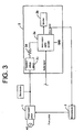
- Fig. 3 is a schematic diagram showing an example of a portion related to shutting off the power that is supplied to the audio equipment when an abnormal operation occurs in the flat-panel television apparatus.
- a power supply circuit 1 is a partial resonance power supply circuit; it converts an external power, for example, a commercial AC power into a plurality of types of predetermined voltages, and outputs the operating power voltages to all portions of the flat-panel television apparatus.
- Audio equipment 2 comprises mainly an audio output amplifier IC 2a that outputs a sound from a speaker 2b based on an audio signal and a constant voltage circuit 2c that output a constant voltage to the audio output amplifier IC 2a.
- This audio output amplifier IC 2a outputs a high signal as an error signal when abnormalities, such as output short, thermal shutdown, reduced voltage detection, and instantaneous interruption detection, for example, occur.
- a microcomputer 3 judges that the system is in an abnormal state, and outputs an OFF signal Poff in place of an ON signal Pon as a signal to order ON/OFF of the power supply circuit 1. Thereby, the power supply circuit 1 is turned off, and the outputs of all the operating voltages are stopped, enabling to protect the audio output amplifier IC and other parts from heating due to the abnormal state.
- Japanese Unexamined Patent Application Publication No. Hei7 (1995) -78941 discloses a system of an overheat protection circuit by means of a semiconductor integrated circuit (IC), wherein it includes a shutoff circuit that stops the operations of a temperature monitoring circuit and other main circuits in the IC chip according to the output of the detected temperature, and the shutoff circuit includes a timer circuit section, whereby the system judges whether or not the signal of the temperature monitoring circuit is high for more than a predetermined time, and stops the operation of the the main circuit after judging that the signal is high for more than a predetermined time.
- IC semiconductor integrated circuit
- Japanese Unexamined Patent Application Publication No. Hei7 (1995)-13643 discloses a system of an overheat protection circuit, wherein it does not output a shutoff signal even if a malfunction occurs in the shutoff circuit when it turns on or off the power under a high temperature condition due to the degradation of the heat dissipation efficiency.
- Japanese Unexamined Patent Application Publication No. 2000-47848 discloses an audio output control system, wherein it automatically returns to the normal operation without performing any external manipulations even if the sound synthesis IC runs out of control.
- a signal processing unit of audio equipment comprising: a multi-channel decoder (MCD) or a digital interface receiver (DIR), a digital signal processor (DSP), and a microcomputer as an integrated circuit (IC); wherein a forcible mute circuit, which acts like an AND circuit by forcibly zeroing the output signal of the DSP according to the error detection data that is output from the MCD or DIR and muting the circuit, is provided in the latter part of the DSP.
- MCD multi-channel decoder
- DIR digital interface receiver
- DSP digital signal processor
- IC integrated circuit
- the present invention is made by taking the above-described problem into consideration, and it presents audio equipment that can prevent the continuation of the halfway abnormal operations and a flat-panel television provided with the audio equipment.
- one embodiment of the present invention includes an audio equipment, comprising:an audio output amplifier and a speaker, with a sound output from the speaker based on an audio signal that is input in the audio output amplifier, and with a high signal output as an error signal to protect the audio output amplifier when an abnormal operation occurs.
- the audio equipment further comprising a rectifier circuit to stabilize the error signal.
- FIG. 1 is a block diagram illustrating the configuration of a liquid crystal television apparatus 10 as a flat-panel television to which the present invention is applied.
- the liquid crystal television apparatus includes a tuner 11, a front end 12, a decoder 13, an OSD circuit 14, an audio output section 15, an image display section 16, a remote control receiver 17, a microcomputer 18, and a power supply circuit 19.
- the tuner 11 which is connected, for example, to an antenna 20, gets a television broadcast signal corresponding to one channel (for example, a channel selected by the user) among the television broadcast signals received by the antenna 20 following the control signal that is input from the microcomputer 18, and outputs the signal to the front end 12.
- the front end 12 converts the television broadcast signal, which is output from the tuner 11 following the control signal that is input, for example, from the microcomputer 18, into an intermediate frequency signal, and outputs the signal to the decoder 13.
- the decoder 13 separates the intermediate frequency signal into the audio signal and the image signal, and decodes them by applying the processing according to the predetermined file format (for example, the well-known MPEG-2 format or the like) for the intermediate frequency signal that is output from the front end 12 following the control signal that is input, for example, from the microcomputer 18. And, the decoder outputs the decoded audio signal to the audio output section 15, as well as outputs the decoded image signal to the image display section 16.
- the predetermined file format for example, the well-known MPEG-2 format or the like
- the OSD circuit 14 merges the OSD display signal for performing a predetermined OSD display (on-screen display) on the image display section 16 into the image signal that is output from the decoder 13 to the image display section 16 following the control signal that is input, for example, from the microcomputer 18.
- the audio output section 15 functions as audio equipment that outputs a sound according to the audio data based on the audio signal that is output from the decoder 13.
- the image display section 16 includes, for example, a panel drive circuit 16a, a liquid crystal panel 16b, and other devices; and it displays an image according to the image data based on the image signal that is output from the decoder 13, and an image according to the image data based on the image signal that is output from the decoder 13 and merged with the OSD display signal by the OSD circuit 14.
- the remote control receiver 17 receives various signals (control commands) that are transmitted, for example, from a remote controller 21, and outputs various data to the microcomputer 18 based on the various signals.
- the remote controller 21 is operated, for example, by the user, and it transmits the signal corresponding to the operation to the remote control receiver 17. More specifically, the remote controller 21 includes channel keys, up/down keys, and other keys, which are used when the user specifies a channel to select or other purposes.
- the microcomputer 18 includes, for example, CPU18a, RAM18b, ROM18c, and other parts; and it controls the liquid crystal television apparatus 10. For example, the microcomputer 18 controls the channel switching and the volume up/down based on the control commands received by the remote control receiver 17.
- CPU18a performs various control operations following the various processing programs recorded in ROM18c for the liquid crystal television apparatus 10.
- RAM18b includes a program storage area for unfolding the processing program to be executed by CPU18a, securing a data storage area for input data, and storing the processed results and other data that are produced when the processing programs are executed.
- ROM18c records a system program that can be executed in the liquid crystal television apparatus 10, various processing programs that can be executed in the system program, data that can be used when executing these various processing programs, the data of various results that are processed by CPU1 8a, and other data.
- the programs are recorded in ROM18c in the format of loadable program code.
- the power supply circuit 19 is, for example, a partial resonance power supply circuit; it converts a commercial AC power into a plurality of types of predetermined voltages and outputs the operating power voltages to all portions of the liquid crystal television apparatus.
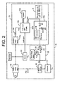
- FIG. 2 is a schematic configuration diagram illustrating in more concrete form the portion on the audio output section 15 as audio equipment in the liquid crystal television apparatus 10 shown in Fig. 1 .
- the audio output section 15 includes an audio output amplifier IC (D-AMP) 15a, a speaker 15b, a constant voltage circuit 15c that supplies a constant voltage Vcc to the audio output amplifier IC 158a based on the output voltage from the power supply circuit 19, a resistor 15d, a rectifier circuit 15e, and other devices.
- D-AMP audio output amplifier
- the audio output amplifier IC 15a applies a predetermined processing such as power amplification to the audio signal that is input from the decoder 13, outputs the audio signal to the speaker 15b to output a sound from the speaker 15b.
- this audio output amplifier IC 15a outputs a high signal "H" as an error signal Error to protect the audio output amplifier IC 15a itself when abnormalities, such as output short, thermal shutdown, reduced voltage detection, and instantaneous interruption detection, for example, occur.
- the audio output section 15 in the present embodiment includes the rectifier circuit 15e to stabilize the error signal Error.
- the rectifier circuit 15e includes a diode D1 and a capacitor C1 whose one terminal is connected to the cathode side of the diode D1 and the other terminal is grounded.
- the rectifier circuit 15e stabilizes the error signal Error by smoothing the signal and outputs the error signal after stabilization FError to the diode D1.
- the averaged value of the error signal Error is output to the error signal after stabilization FError as shown at B in Fig. 2 .
- the error signal after stabilization FError which is output from the rectifier circuit 15e, becomes a signal to activate an abnormality signal output circuit 22 that outputs an abnormal state detection signal Se to the microcomputer 18, for example, to turn off the power supply circuit 19 when the abnormal state occurs.
- the abnormality signal output circuit 22 includes a first transistor Tr1 whose base is connected to the cathode side of the diode D1, and a second transistor Tr2 whose emitter is connected to a signal voltage source 23 of the abnormal state detection signal Se to detect the abnormal state and the collector is connected to the microcomputer 18; when the voltage of the error signal after stabilization FError becomes more than a predetermined voltage and the first transistor Tr1 is turn on, the second transistor Tr2 is also turned on and the error signal is output to the microcomputer 18 as the abnormal state detection signal Se.
- the microcomputer 18 judges that the audio equipment is in an abnormal state, and outputs the OFF signal Poff replaced with the ON signal Pon as a signal to direct on or off of the power supply circuit 19. Thereby, the power supply circuit 19 is turned off to shut off the power supplied to the audio output amplifier IC 15a and other devices, enabling to protect the audio output amplifier IC 15a and other devices from heating due to the abnormal state.
- the rectifier circuit 15e smoothes the error signal Error to convert it into the error signal after stabilization FError even if the error signal Error that might oscillate irregularly between high and low is input in the rectifier circuit 15e; thereby enabling it to properly detect an abnormal state even when a halfway abnormal operation occurs such as when the error signal oscillates irregularly between high and low, and the power supplied to the audio output amplifier IC 15a is definitely shut off.
- the error signal Error is stabilized, it becomes also possible to shorten the required time when the microcomputer 18 judges the abnormal state.
- the system can detect the abnormal state of the audio output section 15 quickly and definitely, and prevent the continuation of the halfway abnormal operations. Therefore, it is possible to easily prevent the durability and quality of the parts of the audio output section 15 from degrading due to the continuation of the halfway abnormal operations without performing the measures against heating that become excessive quality except when the halfway abnormal operations occur. In addition, because the power supply control becomes able to be done with few false operations, the continuation of the halfway abnormal operations can easily be prevented.
- the rectifier circuit 15e consists of the diode D1 and capacitor C1, it can easily smooth the error signal Error to covert it into the error signal after stabilization FError. It can easily convert the error signal Error that might oscillate between high and low, in particular, into a stable signal output
- the abnormal state detection signal Se which is detected based on the condition that the error signal after stabilization FError for which the rectifier circuit 15e stabilizes the error signal Error is more than a predetermined voltage, is output to the microcomputer 18, when the microcomputer shuts off the power supplied to the audio output amplifier IC 15a based on the condition that the abnormal state detection signal Se are continuously input for a predetermined time, the microcomputer 18 can perform a stable power supply control with few false operations when a halfway abnormal operation occurs, and can easily prevent the continuation of the halfway abnormal operations.
- the microcomputer 18 stably judges the abnormal state. Therefore, the stable abnormal state detection signal Se is output to the microcomputer 18 by the abnormality signal output circuit 22 when a halfway abnormal operation occurs, thereby enabling the microcomputer 18 to perform the power supply control with few false operations, and to easily prevent the continuation of the halfway abnormal operations.
- the audio equipment of the present invention even if an error signal that might oscillate between a high signal and a low signal is input in the rectifier circuit, it can, for example, smooth the error signal to convert it into a stable signal. And because the error signal can be stabilized by the rectifier circuit, the system can properly detect the abnormal state even when a halfway abnormal operation occurs such as when the error signal oscillates between a high signal and a low signal. Therefore, the system can detect the abnormal state of the audio equipment quickly and definitely, and prevent the continuation of the halfway abnormal operations. With this, it is possible to easily prevent the durability and quality of the parts of the audio equipment from degrading due to the continuation of the halfway abnormal operations without performing the measures against heating that become excessive quality except when the halfway abnormal operations occur.
- the rectifier circuit includes a diode and a capacitor with one terminal connected to a cathode side of the diode and an other terminal grounded; and when the error signal is input in an anode side of the diode, the error signal is rectified and output from the cathode side of the diode. According to this invention, even if an error signal that might oscillate between a high signal and a low signal is input in the rectifier circuit, it can easily rectify the error signal to convert it into a stable signal.
- the power supplied to the audio output amplifier is shut off based on the output from the rectifier circuit.
- the power supplied to the audio output amplifier is definitely shut off even when a halfway abnormal operation occurs such as when the error signal oscillates between a high signal and a low signal. Therefore, as it becomes possible to perform the power supply control with few false operations, the continuation of the halfway abnormal operations can easily be prevented.
- the abnormal state detection signal based on the condition that the output from the rectifier circuit is more than a predetermined voltage is output to the microcomputer.
- This microcomputer shuts off the power supplied to the audio output amplifier when the abnormal state detection signal is input continuously for a predetermined time. According to this invention, it becomes possible to perform the power supply control by means of the microcomputer stably even when a halfway abnormal operation occurs such as when the error signal oscillates between a high signal and a low signal. Therefore, as it becomes possible to perform the power supply control by means of the microcomputer stably with few false operations when a halfway abnormal operation occurs, the continuation of the halfway abnormal operations can easily be prevented.
- the error signal rectified by the rectifier circuit is output to the abnormality signal output circuit.
- This abnormality signal output circuit includes a first transistor with a base coupled with the cathode side of the diode, and a second transistor with a base grounded through the first transistor, an emitter coupled with a signal voltage source of the abnormal state detection signal, and a collector coupled with the microcomputer.
- the microcomputer shuts off the power supplied to the audio output amplifier by judging that the audio equipment is in an abnormal state.
- the judgment of an abnormal state by means of the microcomputer is stably performed even when a halfway abnormal operation occurs such as when the error signal oscillates between a high signal and a low signal. Therefore, when a halfway abnormal operation occurs, the stable above-described abnormal state detection signal is output to the microcomputer by means of the abnormality signal detection circuit; and as it becomes possible to perform the power supply control by means of the microcomputer with few false operations, the continuation of the halfway abnormal operations can easily be prevented.
- the present invention can also be realized by using a flat-panel television for which the above-mentioned configuration takes a further concrete form; as a concrete example of the configuration, the flat-panel television of the present invention outputs a sound from a speaker based on an audio signal inputted in an audio output amplifier, and includes audio equipment that outputs a high signal as an error signal to protect the audio output amplifier when an abnormal operation occurs.
- This audio equipment includes a rectifier circuit to stabilize the error signal.
- This rectifier circuit includes a diode and a capacitor with one terminal connected to a cathode side of the diode and another terminal grounded; and when the error signal is input in an anode side of the diode, a stabilized signal is output by smoothing the error signal from the cathode side of the diode; the stabilized signal is output to an abnormality signal output circuit.
- This abnormality signal output circuit includes a first transistor with a base coupled with the cathode side of the diode, and a second transistor witha base grounded through the first transistor; an emitter coupled with a signal voltage source of an abnormal state detection signal to detect an abnormal state; and a collector coupled with a microcomputer; and when the voltage of the stabilized signal becomes more than a predetermined voltage and the first transistor is turn on, the second transistor is also turned on, and a high signal as the abnormal state detection signal is output to the microcomputer.
- this microcomputer judges that the audio equipment is in an abnormal state, and shuts off the power supplied to the audio output amplifier.
- the rectifier circuit can smooth the error signal to convert it into a stable signal output.
- the error signal can be stabilized by the rectifier circuit, even when a halfway abnormal operation occurs such as when the error signal oscillates between a high signal and a low signal, the voltage of the signal after stabilization becomes more than a predetermined voltage; and when the first transistor is turn on, the second transistor is also turned on, and a high signal as the abnormal state detection signal is output to the microcomputer, thereby enabling it to detect the abnormal state properly. And the power supplied to the audio output amplifier is shut off definitely.
- the system can detect the abnormal state of the audio equipment quickly and definitely, and prevent the continuation of the halfway abnormal operations. With this, it is possible to easily prevent the durability and quality of the parts of the audio equipment from degrading due to the continuation of the halfway abnormal operations without performing the measures against heating that become excessive quality except when the halfway abnormal operations occur. Also, it is possible to convert the error signal that might oscillate between a high signal and a low signal into a stable signal output. Also, it becomes possible to perform the power supply control with few false operations, so the continuation of the halfway abnormal operations can easily be prevented.
- the power supply circuit 19 was turned off when the microcomputer 18 judged that the system is in a abnormal state; however, it is allowed that the power supply circuit 19 remains on, and, for example, only the constant voltage circuit 15c is turned off to shut off the power supplied to the audio output amplifier IC 15a.
- the power supply circuit 19 remains on, it is also possible to perform the OSD display using the OSD circuit 14 showing that the power of the audio system is off and the audio output is presently stopped.
- the power supplied to the audio output amplifier IC 15a was turned off by the power supply control using the microcomputer 18; however, it is allowed that the power supplied to the audio output amplifier IC 15a is turned off, for example, by activating the switching transistor based on the error signal after stabilization FError and directly controlling the power supply circuit 19 and the constant voltage circuit 15c. If this modification is applied to the embodiment described above, even when the microcomputer 18 becomes abnormal, the power supplied to the audio output amplifier IC 15a can be turned off definitely.
Landscapes
- Engineering & Computer Science (AREA)
- Power Engineering (AREA)
- Television Receiver Circuits (AREA)
- Amplifiers (AREA)
Applications Claiming Priority (1)
| Application Number | Priority Date | Filing Date | Title |
|---|---|---|---|
| JP2007096465A JP2008258749A (ja) | 2007-04-02 | 2007-04-02 | 薄型テレビジョン、および音響装置 |
Publications (2)
| Publication Number | Publication Date |
|---|---|
| EP1978637A2 true EP1978637A2 (fr) | 2008-10-08 |
| EP1978637A3 EP1978637A3 (fr) | 2014-07-16 |
Family
ID=39665855
Family Applications (1)
| Application Number | Title | Priority Date | Filing Date |
|---|---|---|---|
| EP08006378.7A Withdrawn EP1978637A3 (fr) | 2007-04-02 | 2008-03-31 | Télévision à écran plat et équipement audio |
Country Status (3)
| Country | Link |
|---|---|
| US (1) | US8243968B2 (fr) |
| EP (1) | EP1978637A3 (fr) |
| JP (1) | JP2008258749A (fr) |
Families Citing this family (5)
| Publication number | Priority date | Publication date | Assignee | Title |
|---|---|---|---|---|
| JP5533101B2 (ja) * | 2010-03-23 | 2014-06-25 | ヤマハ株式会社 | オーディオアンプ装置 |
| CN106412761B (zh) | 2011-12-30 | 2020-02-14 | 意法半导体研发(深圳)有限公司 | 用于汽车音频功率放大器的嵌入式扬声器保护 |
| CN102868850B (zh) * | 2012-08-16 | 2015-10-14 | 浙江宇视科技有限公司 | 一种摄像机加热装置 |
| US9503033B2 (en) * | 2013-03-28 | 2016-11-22 | Hewlett-Packard Development Company, L.P. | Audio amplifier mode transition |
| TWI745801B (zh) * | 2019-12-17 | 2021-11-11 | 廣達電腦股份有限公司 | 音訊輸出裝置及其保護方法 |
Citations (4)
| Publication number | Priority date | Publication date | Assignee | Title |
|---|---|---|---|---|
| JPH0713643A (ja) | 1993-06-29 | 1995-01-17 | Mitsubishi Electric Corp | 半導体集積回路の過熱保護回路 |
| JPH0778941A (ja) | 1993-06-30 | 1995-03-20 | Mitsubishi Electric Corp | 半導体集積回路における過熱保護回路 |
| JP2000047848A (ja) | 1998-07-28 | 2000-02-18 | Matsushita Electric Works Ltd | 音声出力制御システム |
| JP2002150723A (ja) | 2000-11-07 | 2002-05-24 | Victor Co Of Japan Ltd | 音響機器の信号処理装置 |
Family Cites Families (9)
| Publication number | Priority date | Publication date | Assignee | Title |
|---|---|---|---|---|
| US3731153A (en) * | 1970-08-27 | 1973-05-01 | Sansui Electric Co | Protective device for loudspeaker |
| GB1433334A (en) * | 1972-06-20 | 1976-04-28 | Nat Res Dev | Single side-band radio |
| US3825697A (en) * | 1973-07-27 | 1974-07-23 | Gen Motors Corp | Phase-lock-loop fm-stereo decoder including stereophonic/monophonic blend system for reducing audio distortion |
| US3894201A (en) * | 1974-05-31 | 1975-07-08 | Rca Corp | System for dynamic and static muting |
| US3959735A (en) * | 1975-06-16 | 1976-05-25 | Gte Sylvania Incorporated | Loudspeaker and amplifier protection circuit |
| US5103675A (en) * | 1989-12-20 | 1992-04-14 | Komninos Nikolaos I | Signal detector and method for detecting signals having selected frequency characteristics |
| JP2004312401A (ja) * | 2003-04-08 | 2004-11-04 | Sony Corp | 再生装置および再生方法 |
| JP4251111B2 (ja) * | 2004-05-28 | 2009-04-08 | ソニー株式会社 | 電源制御装置、電源回路の制御方法 |
| JP2007274812A (ja) * | 2006-03-31 | 2007-10-18 | Brother Ind Ltd | スピーカ付装置 |
-
2007
- 2007-04-02 JP JP2007096465A patent/JP2008258749A/ja active Pending
-
2008
- 2008-03-28 US US12/079,653 patent/US8243968B2/en not_active Expired - Fee Related
- 2008-03-31 EP EP08006378.7A patent/EP1978637A3/fr not_active Withdrawn
Patent Citations (4)
| Publication number | Priority date | Publication date | Assignee | Title |
|---|---|---|---|---|
| JPH0713643A (ja) | 1993-06-29 | 1995-01-17 | Mitsubishi Electric Corp | 半導体集積回路の過熱保護回路 |
| JPH0778941A (ja) | 1993-06-30 | 1995-03-20 | Mitsubishi Electric Corp | 半導体集積回路における過熱保護回路 |
| JP2000047848A (ja) | 1998-07-28 | 2000-02-18 | Matsushita Electric Works Ltd | 音声出力制御システム |
| JP2002150723A (ja) | 2000-11-07 | 2002-05-24 | Victor Co Of Japan Ltd | 音響機器の信号処理装置 |
Also Published As
| Publication number | Publication date |
|---|---|
| JP2008258749A (ja) | 2008-10-23 |
| EP1978637A3 (fr) | 2014-07-16 |
| US20080240469A1 (en) | 2008-10-02 |
| US8243968B2 (en) | 2012-08-14 |
Similar Documents
| Publication | Publication Date | Title |
|---|---|---|
| US6593975B1 (en) | Method for controlling a power saving mode of a video display device with respect to a predetermined one of a plurality of applied signal sources | |
| US7145609B2 (en) | Method and apparatus of processing input signals of display appliance | |
| KR950005216B1 (ko) | 컴퓨터 주변장치의 전원절약장치 | |
| EP1978637A2 (fr) | Télévision à écran plat et équipement audio | |
| US6650376B1 (en) | Controller of tuner apparatus and method for controlling power supply to tuner of tuner apparatus | |
| US7779283B2 (en) | Computer and method for realizing household appliance application with low power consumption | |
| US20090237384A1 (en) | Display device and method of automatically powering on and powering off the same | |
| US20060282693A1 (en) | Device and method for power management in a display device | |
| US20050060122A1 (en) | Method and device for monitoring | |
| US5341179A (en) | Source voltage control switching circuit | |
| US6424875B1 (en) | Method and circuit for controlling power of audio processor in monitor | |
| US7203856B2 (en) | Mobile computer with desktop type processor | |
| JP2001125556A (ja) | 電子機器 | |
| US6448963B1 (en) | Device for and method of coding error generated in processing sync signals | |
| KR100710259B1 (ko) | 영상기기의 전원 관리 방법 및 그 영상기기 | |
| KR100744508B1 (ko) | 절전(Display Power Management)모드 기능을 구비한 영상기기 및 그 제어방법 | |
| US8077879B2 (en) | Audio output apparatus and television broadcast receiver | |
| US20090055664A1 (en) | Communication Device | |
| KR20030042045A (ko) | 모니터와 티브이화면의 전환 시스템 | |
| KR100732165B1 (ko) | 영상기기의 전원 관리 방법 및 장치 | |
| US8542001B2 (en) | Power circuit for reducing standby power consumption | |
| KR100755860B1 (ko) | 오디오잭 감지를 통한 소비전력 절감 장치 및 방법 | |
| KR970073046A (ko) | 스탠바이상태에서의 티브이(tv) 전력소모 절감회로 | |
| KR19990034115U (ko) | 멀티미디어용 모니터의 전원 절전 회로 | |
| JPH11119842A (ja) | 保護回路、保護処理制御方法および保護処理制御プログラムを記録した媒体 |
Legal Events
| Date | Code | Title | Description |
|---|---|---|---|
| PUAI | Public reference made under article 153(3) epc to a published international application that has entered the european phase |
Free format text: ORIGINAL CODE: 0009012 |
|
| AK | Designated contracting states |
Kind code of ref document: A2 Designated state(s): AT BE BG CH CY CZ DE DK EE ES FI FR GB GR HR HU IE IS IT LI LT LU LV MC MT NL NO PL PT RO SE SI SK TR |
|
| AX | Request for extension of the european patent |
Extension state: AL BA MK RS |
|
| PUAL | Search report despatched |
Free format text: ORIGINAL CODE: 0009013 |
|
| AK | Designated contracting states |
Kind code of ref document: A3 Designated state(s): AT BE BG CH CY CZ DE DK EE ES FI FR GB GR HR HU IE IS IT LI LT LU LV MC MT NL NO PL PT RO SE SI SK TR |
|
| AX | Request for extension of the european patent |
Extension state: AL BA MK RS |
|
| RIC1 | Information provided on ipc code assigned before grant |
Ipc: H03F 1/52 20060101AFI20140612BHEP |
|
| AKY | No designation fees paid | ||
| AXX | Extension fees paid |
Extension state: MK Extension state: BA Extension state: RS Extension state: AL |
|
| REG | Reference to a national code |
Ref country code: DE Ref legal event code: R108 |
|
| REG | Reference to a national code |
Ref country code: DE Ref legal event code: R108 Effective date: 20150325 |
|
| STAA | Information on the status of an ep patent application or granted ep patent |
Free format text: STATUS: THE APPLICATION IS DEEMED TO BE WITHDRAWN |
|
| 18D | Application deemed to be withdrawn |
Effective date: 20150117 |