EP1978537B1 - Contactor with duct and load branch with such a contactor - Google Patents
Contactor with duct and load branch with such a contactor Download PDFInfo
- Publication number
- EP1978537B1 EP1978537B1 EP07006733A EP07006733A EP1978537B1 EP 1978537 B1 EP1978537 B1 EP 1978537B1 EP 07006733 A EP07006733 A EP 07006733A EP 07006733 A EP07006733 A EP 07006733A EP 1978537 B1 EP1978537 B1 EP 1978537B1
- Authority
- EP
- European Patent Office
- Prior art keywords
- additional
- contactor
- central area
- main
- main connector
- Prior art date
- Legal status (The legal status is an assumption and is not a legal conclusion. Google has not performed a legal analysis and makes no representation as to the accuracy of the status listed.)
- Active
Links
Images

Classifications
-
- H—ELECTRICITY
- H01—ELECTRIC ELEMENTS
- H01H—ELECTRIC SWITCHES; RELAYS; SELECTORS; EMERGENCY PROTECTIVE DEVICES
- H01H71/00—Details of the protective switches or relays covered by groups H01H73/00 - H01H83/00
- H01H71/08—Terminals; Connections
-
- H—ELECTRICITY
- H01—ELECTRIC ELEMENTS
- H01H—ELECTRIC SWITCHES; RELAYS; SELECTORS; EMERGENCY PROTECTIVE DEVICES
- H01H71/00—Details of the protective switches or relays covered by groups H01H73/00 - H01H83/00
- H01H71/08—Terminals; Connections
- H01H2071/086—Low power connections for auxiliary switches, e.g. shunt trip
-
- H—ELECTRICITY
- H01—ELECTRIC ELEMENTS
- H01H—ELECTRIC SWITCHES; RELAYS; SELECTORS; EMERGENCY PROTECTIVE DEVICES
- H01H89/00—Combinations of two or more different basic types of electric switches, relays, selectors and emergency protective devices, not covered by any single one of the other main groups of this subclass
- H01H89/06—Combination of a manual reset circuit with a contactor, i.e. the same circuit controlled by both a protective and a remote control device
Definitions
- Such contactors and such load branches are well known. Often, in the contactor main actuators, by means of which the main terminals are actuated, accessible from the edge regions. Furthermore, additional operating elements by means of which the additional terminals can be actuated are often accessible from the central area.
- cables are clamped in the additional terminals of both additional connection areas. At least those additional lines, which are clamped in an additional terminal facing the accessory, must therefore be performed either over the central region and the side facing away from the attachment edge region or on the attachment.
- This approach is disadvantageous because it affects access to the contactor or the attachment and the view of the contactor or the attachment. Furthermore, this embodiment is unaesthetic.
- a low-voltage circuit breaker having a front and a rear wall having housing, the front wall of the rear wall opposite and is formed as an operating side.
- the housing further comprises two side and a bottom and a top surface, which connect the front and the rear wall.
- the side surfaces are on the one hand opposite each other and the bottom and the top surface are on the other hand opposite each other.
- a cable channel is integrated, which extends substantially over the entire width of the low-voltage circuit breaker and in the direction of the housing front wall has one or more passages for passing connecting lines between current transformers and a front electronic trip unit.
- the object of the present invention is to provide a way to avoid the disadvantages mentioned above.
- the object is achieved in a contactor of the type mentioned above in that in the central region a duct is introduced, which extends from the one of the edge regions to the other of the edge regions.
- the object for the load branch described above is achieved in that the contactor is designed as described last and the at least one additional line is guided through the duct.
- the duct runs parallel to the side surfaces. It can be arranged centrally in relation to the side surfaces. Preferably, however, the duct is located closer to one side surface than to the other side surface.
- the duct has one of the side wall facing a channel wall and the other side surface facing channel wall.
- the channel wall facing the other side surface is arranged closer to the one side surface than to the other side surface.
- the contactor has a plunger.
- the plunger is accessible from the central area.
- the plunger is arranged closer to the other side surface than on the one side surface.
- the duct can be covered by a flap. It is possible that the flap covers the duct and other elements - for example, the entire central area. Preferably, however, by means of the flap only the duct can be covered.
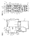
- FIG. 1 has a load feeder on a contactor 1 and an accessory 2.
- the load branch is arranged between a power grid 3 and a load 4.
- the attachment 2 is according to FIG. 1 designed as a circuit breaker. It is upstream of the contactor 1.
- the contactor 1 has a housing 5.
- the housing 5 has a mounting side 6, an operating side 7, two main connection surfaces 8, 8 'and two side surfaces 9, 9'.
- the operator side 7 is opposite to the mounting side 6.
- the main connection surfaces 8, 8 ' are opposite each other.
- the side surfaces 9, 9 ' face each other.
- the operating side 7 has a raised central region 10 and two edge regions 11, 11 'adjoining the middle region 10 on both sides of the middle region 10.
- FIG. 1 Schematically illustrated main terminals 13, 13 ', which are connected to load contacts 14 of the contactor 1, have main receiving openings 15, 15'.
- the main receiving openings 15, 15 ' are main lines 16, 16' insertable.
- the insertability is in this case given by one of the main connection surfaces 8, 8 '.
- the contactor 1 further comprises schematically indicated additional terminals 17, 17 '.
- the additional terminals 17, 17 'additional lines 18, 18' to the contactor 1 can be connected.
- the additional terminals 17, 17' have additional receiving openings 19, 19 ', in which the additional lines 18, 18th 'are insertable.
- the additional lines 18, 18 'are in this case of one of the additional connection surfaces 12, 12' from in the additional receiving openings 19, 19 'insertable.
- main terminals 13, 13 ' are designed as screw terminals.
- main operating elements 20, 20 '(namely screws), by means of which the main clamps 13, 13' are actuated, are accessible from the edge regions 11, 11 '.
- the additional terminals 17, 17 ' are also designed as screw terminals.
- additional operating elements 21, 21 ' (namely screws again), by means of which the additional terminals 17, 17' are actuated, accessible from the central region 10 from.
- the attachment 2 is mechanically and electrically connected to the contactor 1 on one of the main connection surfaces 8, 8 '.
- an intermediate element 22 may be arranged, which causes the electrical and mechanical connection of the auxiliary device 2 with the contactor 1.
- a duct 23 is introduced, which extends from the one of the edge regions 11, 11 'to the other of the edge regions 11, 11'. Through the duct 23 through at least one of the additional lines 18 is guided, which is clamped in one of the auxiliary device 2 facing additional terminals 17.
- the reference numeral 24 denotes a center line, which runs centrally between the side surfaces 9. As can be seen, the duct 23 extends parallel to the side surfaces 9, but is arranged off-center, namely closer to one side surface 9 than to the other side surface 9 '.
- the duct 23 has two channel walls 25, 25 '.
- the one channel wall 25 faces the one side surface 9, the other channel wall 25 'of the other side surface 9'.
- the other side surface 9 'facing channel wall 25' is arranged closer to the one side surface 9 than on the other side surface 9 '.
- the duct 23 is in the embodiment of FIGS. 2 and 3 thus completely closer to the one side surface 9 arranged as on the other side surface 9 '.
- the duct 23 is preferably coverable by means of a flap 26.
- the conduit 23 can be covered. It would be, however alternatively possible to cover also other elements - in particular the entire central region 10 - with the flap 26.
- the contactor 1 has a plunger 27.
- the plunger 27 is according to FIG. 3 accessible from the central area 10.
- the plunger 27 is in this case arranged closer to the other side surface 9 'than on the one side surface 9. It is thus also arranged off-center.
- an auxiliary device can be actuated, the operator side of the contactor 1 can be attached.
Abstract
Description
Die vorliegende Erfindung betrifft ein Schütz, das wie folgt aufgebaut ist:
- Es weist ein Gehäuse auf, das eine Montageseite, eine Bedienseite, zwei Hauptanschlussflächen und zwei Seitenflächen aufweist.
- Die Bedienseite liegt der Montageseite gegenüber und ist mit der Montageseite über die Hauptanschlussflächen und die Seitenflächen verbunden, wobei die Hauptanschlussflächen einander gegenüber liegen und die Seitenflächen einander gegenüber liegen.
- Die Bedienseite weist einen erhabenen Mittelbereich und zwei beidseits des Mittelbereichs an den Mittelbereich angrenzende Randbereiche auf, wobei die Randbereiche an die Hauptanschlussflächen angrenzen und mit dem Mittelbereich über je eine Zusatzanschlussfläche verbunden sind.
- Hauptklemmen, die mit Lastkontakten des Schützes verbunden sind, weisen Hauptaufnahmeöffnungen auf, in die von je einer der Hauptanschlussflächen aus Hauptleitungen einführbar sind.
- Zusatzklemmen, über die Zusatzleitungen an das Schütz anschließbar sind, weisen Zusatzaufnahmeöffnungen auf, in die von je einer der Zusatzanschlussflächen aus die Zusatzleitungen einführbar sind.
- It has a housing which has a mounting side, an operating side, two main connection surfaces and two side surfaces.
- The operating side faces the mounting side and is connected to the mounting side via the main connection surfaces and the side surfaces, with the main connection surfaces facing each other and the side surfaces facing each other.
- The operating side has a raised center region and two edge regions adjoining the middle region on both sides of the middle region, wherein the edge regions adjoin the main connection surfaces and are connected to the middle region via an additional connection surface each.
- Main terminals, which are connected to load contacts of the contactor, have main receiving openings, in each of which one of the main connection surfaces of main lines can be inserted.
- Additional terminals, via the additional cables can be connected to the contactor, have additional receiving openings, in each of which one of the additional connection surfaces from the additional lines can be inserted.
Die vorliegende Erfindung betrifft weiterhin einen Lastabzweig, bestehend aus einem Schütz der obenstehend beschriebenen Art und einem Zusatzgerät,
- wobei das Zusatzgerät mit dem Schütz an einer der Hauptanschlussflächen mechanisch und elektrisch verbunden ist,
- wobei mindestens eine Zusatzleitung in einer der dem Zusatzgerät zugewandten Zusatzklemmen geklemmt ist.
- wherein the attachment is mechanically and electrically connected to the contactor on one of the main connection pads,
- wherein at least one additional line is clamped in one of the auxiliary device facing additional terminals.
Derartige Schütze und derartige Lastabzweige sind allgemein bekannt. Oftmals sind bei dem Schütz Hauptbetätigungselemente, mittels derer die Hauptklemmen betätigbar sind, von den Randbereichen aus zugänglich. Weiterhin sind oftmals Zusatzbetätigungselemente, mittels derer die Zusatzklemmen betätigbar sind, vom Mittelbereich aus zugänglich.Such contactors and such load branches are well known. Often, in the contactor main actuators, by means of which the main terminals are actuated, accessible from the edge regions. Furthermore, additional operating elements by means of which the additional terminals can be actuated are often accessible from the central area.
In der Regel werden in den Zusatzklemmen beider Zusatzanschlussbereiche Leitungen geklemmt. Zumindest diejenigen Zusatzleitungen, die in einer dem Zusatzgerät zugewandten Zusatzklemme geklemmt sind, müssen daher entweder über den Mittelbereich und den vom Zusatzgerät abgewandten Randbereich geführt werden oder über das Zusatzgerät. Diese Vorgehensweise ist nachteilig, weil sie den Zugang zu dem Schütz oder dem Zusatzgerät und den Einblick auf das Schütz oder das Zusatzgerät beeinträchtigt. Ferner ist diese Ausgestaltung unästhetisch.As a rule, cables are clamped in the additional terminals of both additional connection areas. At least those additional lines, which are clamped in an additional terminal facing the accessory, must therefore be performed either over the central region and the side facing away from the attachment edge region or on the attachment. This approach is disadvantageous because it affects access to the contactor or the attachment and the view of the contactor or the attachment. Furthermore, this embodiment is unaesthetic.
Weiter ist aus dem Dokument
Die Aufgabe der vorliegenden Erfindung besteht darin, eine Möglichkeit zu schaffen, die oben genannten Nachteile zu vermeiden.The object of the present invention is to provide a way to avoid the disadvantages mentioned above.
Die Aufgabe wird bei einem Schütz der eingangs genannten Art dadurch gelöst, dass in den Mittelbereich ein Leitungskanal eingebracht ist, der sich von dem einen der Randbereiche zum anderen der Randbereiche erstreckt.The object is achieved in a contactor of the type mentioned above in that in the central region a duct is introduced, which extends from the one of the edge regions to the other of the edge regions.
Hiermit korrespondierend wird die Aufgabe für den obenstehend beschriebenen Lastabzweig dadurch gelöst, dass das Schütz wie zuletzt beschrieben ausgebildet ist und die mindestens eine Zusatzleitung durch den Leitungskanal geführt ist.Correspondingly, the object for the load branch described above is achieved in that the contactor is designed as described last and the at least one additional line is guided through the duct.
In der Regel verläuft der Leitungskanal parallel zu den Seitenflächen. Er kann hierbei, bezogen auf die Seitenflächen, mittig angeordnet sein. Vorzugsweise jedoch ist der Leitungskanal näher an der einen Seitenfläche angeordnet als an der anderen Seitenfläche.As a rule, the duct runs parallel to the side surfaces. It can be arranged centrally in relation to the side surfaces. Preferably, however, the duct is located closer to one side surface than to the other side surface.
Der Leitungskanal weist eine der einen Seitenfläche zugewandte Kanalwand und eine der anderen Seitenfläche zugewandte Kanalwand auf. Vorzugsweise ist sogar die der anderen Seitenfläche zugewandte Kanalwand näher an der einen Seitenfläche angeordnet als an der anderen Seitenfläche.The duct has one of the side wall facing a channel wall and the other side surface facing channel wall. Preferably, even the channel wall facing the other side surface is arranged closer to the one side surface than to the other side surface.
Das Schütz weist einen Stößel auf. In vielen Fällen ist der Stößel vom Mittelbereich aus zugänglich. Vorzugsweise ist bei dem erfindungsgemäßen Schütz der Stößel näher an der anderen Seitenfläche angeordnet als an der einen Seitenfläche.The contactor has a plunger. In many cases, the plunger is accessible from the central area. Preferably, in the contactor according to the invention, the plunger is arranged closer to the other side surface than on the one side surface.
Der Leitungskanal kann mittels einer Klappe abdeckbar sein. Hierbei ist es möglich, dass die Klappe den Leitungskanal und weitere Elemente - beispielsweise den gesamten Mittelbereich - abdeckt. Vorzugsweise jedoch ist mittels der Klappe ausschließlich der Leitungskanal abdeckbar.The duct can be covered by a flap. It is possible that the flap covers the duct and other elements - for example, the entire central area. Preferably, however, by means of the flap only the duct can be covered.
Weitere Vorteile und Einzelheiten ergeben sich aus der nachfolgenden Beschreibung von Ausführungsbeispielen in Verbindung mit den Zeichnungen. Es zeigen in Prinzipdarstellung:
- FIG 1
- schematisch einen ersten Lastabzweig,
- FIG 2
- den Lastabzweig von
FIG 1 von der Seite, - FIG 3
- den Lastabzweig von FIG von vorne,
- FIG 4
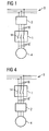
- schematisch einen weiteren Lastabzweig,
- FIG 5
- den Lastabzweig von
FIG 4 von der Seite und - FIG 6
- den Lastabzweig von
FIG 4 von vorne.
- FIG. 1
- schematically a first load branch,
- FIG. 2
- the load branch of
FIG. 1 of the page, - FIG. 3
- the load branch of FIG from the front,
- FIG. 4
- schematically another load branch,
- FIG. 5
- the load branch of
FIG. 4 from the side and - FIG. 6
- the load branch of
FIG. 4 from the front.
Gemäß
Gemäß den
Sie ist mit der Montageseite 6 über die Hauptanschlussflächen 8, 8' und die Seitenflächen 9, 9' verbunden. Die Hauptanschlussflächen 8, 8' liegen einander gegenüber. Ebenso liegen die Seitenflächen 9, 9' einander gegenüber.It is connected to the mounting
Die Bedienseite 7 weist einen erhabenen Mittelbereich 10 und zwei beidseits des Mittelbereichs 10 an den Mittelbereich 10 angrenzende Randbereiche 11, 11' auf. Die Randbereiche 11, 11' grenzen an die Hauptanschlussflächen 8, 8' an. Sie sind mit dem Mittelbereich 10 über je eine Zusatzanschlussfläche 12, 12' verbunden.The
Schematisch dargestellte Hauptklemmen 13, 13', die mit Lastkontakten 14 des Schützes 1 verbunden sind, weisen Hauptaufnahmeöffnungen 15, 15' auf. In die Hauptaufnahmeöffnungen 15, 15' sind Hauptleitungen 16, 16' einführbar. Die Einführbarkeit ist hierbei von je einer der Hauptanschlussflächen 8, 8' aus gegeben.Schematically illustrated
Das Schütz 1 weist weiterhin schematisch angedeutete Zusatzklemmen 17, 17' auf. Über die Zusatzklemmen 17, 17' sind Zusatzleitungen 18, 18' an das Schütz 1 anschließbar. Die Zusatzleitungen 18, 18' dienen beispielsweise dem Abgreifen von Hilfssignalen, dem Zuführen einer Energieversorgung und gegebenenfalls dem separaten Zuführen eines Steuersignals für das Schütz 1. Die Zusatzklemmen 17, 17' weisen Zusatzaufnahmeöffnungen 19, 19' auf, in welche die Zusatzleitungen 18, 18' einführbar sind. Die Zusatzleitungen 18, 18' sind hierbei von je einer der Zusatzanschlussflächen 12, 12' aus in die Zusatzaufnahmeöffnungen 19, 19' einführbar.The
In vielen Fällen sind die Hauptklemmen 13, 13' als Schraubklemmen ausgebildet. Insbesondere in diesem Fall sind Hauptbetätigungselemente 20, 20' (nämlich Schrauben), mittels derer die Hauptklemmen 13, 13' betätigbar sind, von den Randbereichen 11, 11' aus zugänglich.In many cases, the
In vielen Fällen sind weiterhin die Zusatzklemmen 17, 17' ebenfalls als Schraubklemmen ausgebildet. Insbesondere in diese Fall sind Zusatzbetätigungselemente 21, 21' (nämlich wieder Schrauben), mittels derer die Zusatzklemmen 17, 17' betätigbar sind, vom Mittelbereich 10 aus zugänglich.In many cases, the
Das Zusatzgerät 2 ist mit dem Schütz 1 an einer der Hauptanschlussflächen 8, 8' mechanisch und elektrisch verbunden. Gegebenenfalls kann hierbei zwischen dem Schütz 1 und dem Zusatzgerät 2 ein Zwischenelement 22 angeordnet sein, welches die elektrische und mechanische Verbindung des Zusatzgeräts 2 mit dem Schütz 1 bewirkt.The
Gemäß
Mit dem Bezugszeichen 24 ist eine Mittellinie bezeichnet, welche mittig zwischen den Seitenflächen 9 verläuft. Ersichtlich verläuft der Leitungskanal 23 parallel zu den Seitenflächen 9, ist jedoch außermittig angeordnet, nämlich näher an der einen Seitenfläche 9 als an der anderen Seitenfläche 9'.The
Der Leitungskanal 23 weist zwei Kanalwände 25, 25' auf. Die eine Kanalwand 25 ist der einen Seitenfläche 9 zugewandt, die andere Kanalwand 25' der anderen Seitenfläche 9'. Die der anderen Seitenfläche 9' zugewandte Kanalwand 25' ist näher an der einen Seitenfläche 9 angeordnet als an der anderen Seitenfläche 9'. Der Leitungskanal 23 ist in der Ausgestaltung der
Der Leitungskanal 23 ist vorzugsweise mittels einer Klappe 26 abdeckbar. Hierbei ist vorzugsweise mittels der Klappe 26 ausschließlich der Leitungskanal 23 abdeckbar. Es wäre jedoch alternativ möglich, auch weitere Elemente - insbesondere den gesamten Mittelbereich 10 - mit der Klappe 26 abzudecken.The
Das Schütz 1 weist einen Stößel 27 auf. Der Stößel 27 ist gemäß
Die Ausgestaltung gemäß den
dass das Zusatzgerät 2 nicht als Leistungsschalter, sondern als Überlastrelais ausgebildet ist unddass das Zusatzgerät 2dem Schütz 1 nicht vorgeschaltet, sondern nachgeschaltet ist.
- that the
attachment 2 is not designed as a circuit breaker, but as an overload relay and - that the
attachment 2 is not upstream of thecontactor 1, but downstream.
Die beiden Unterschiede der Ausgestaltung der
Die obige Beschreibung dient ausschließlich der Erläuterung der vorliegenden Erfindung. Der Schutzumfang der vorliegenden Erfindung soll hingegen ausschließlich durch die beigefügten Ansprüche bestimmt sein.The above description is only for explanation of the present invention. The scope of the present invention, however, is intended to be determined solely by the appended claims.
Claims (10)
- Contactor, which is constructed as follows:- It has a housing (5), which has a mounting side (6), an operating side (7), two main connector surfaces (8, 8') and two side surfaces (9, 9').- The operating side (7) lies opposite the mounting side (6) and is connected to the mounting side (6) by means of the main connector surfaces (8, 8') and the side surfaces (9, 9'), wherein the main connector surfaces (8, 8') lie opposite one another and the side surfaces (9, 9') lie opposite one another.- The operating side (7) has a raised central area (10) and two edge areas (11, 11'), which border the central area (10) on both sides of the central area (10), wherein the edge areas (11, 11') border the main connector areas (8, 8') and are connected to the central area (10) by means of an additional connector area (12, 12') in each case.- Main terminals (13, 13'), which are connected to the load contacts (14) of the contactor, have main receptacle openings (15, 15') into which main conductors (16, 16') can be fed from one of the main connector surfaces (8, 8') in each case.- Additional terminals (17, 17'), by means of which additional conductors (18, 18') can be connected to the contactor, have additional receptacle openings (19, 19') into which the additional conductors (18, 18') can be fed from one of the additional connector surfaces (12, 12') in each case.- A conductor channel (23), which extends from one of the edge areas (11, 11') to the other edge area (11, 11'), is introduced in the central area (10).
- Contactor according to Claim 1, characterized in that the conductor channel (23) runs parallel to the side surfaces (9, 9') .
- Contactor according to Claim 2, characterized in that the conductor channel (23) is arranged closer to the one side surface (9) than to the other side surface (9').
- Contactor according to Claim 3, characterized in that the conductor channel (23) has a channel wall (25) facing the one side surface (9) and a channel wall (25') facing the other side surface (9') and that the channel wall (25') facing the other side surface (9') is arranged closer to the one side surface (9) than to the other side surface (9').
- Contactor according to Claim 3 or 4, characterized in that the contactor has a plunger (27), that the plunger (27) is accessible from the central area (10), and that the plunger (27) is arranged closer to the other side surface (9') than to the one side surface (9).
- Contactor according to one of the above claims, characterized in that the conductor channel (23) can be covered by means of a flap (26).
- Contactor according to Claim 6, characterized in that only the conductor channel (23) can be covered by means of the flap (26).
- Contactor according to one of the above claims, characterized in that main actuating elements (20, 20'), by means of which the main terminals (13, 13') can be actuated, are accessible from the edge areas (11, 11').
- Contactor according to one of the above claims, characterized in that additional actuating elements (21, 21'), by means of which the additional terminals (17, 17') can be actuated, are accessible from the central area (10).
- Load branch circuit consisting of a contactor (1) according to one of the above claims and an additional device (2),- wherein the additional device (2) is mechanically and electrically connected to the contactor (1) to one of the main connector surfaces (8, 8'),- wherein at least one additional conductor (18, 18') is clamped in one of the additional terminals (17, 17') facing the additional device (2) and is fed through the conductor channel (23).
Priority Applications (5)
| Application Number | Priority Date | Filing Date | Title |
|---|---|---|---|
| AT07006733T ATE538484T1 (en) | 2007-03-30 | 2007-03-30 | CONTACTOR WITH LINE CHANNEL AND LOAD BRANCH WITH SUCH A CONTACTOR |
| EP07006733A EP1978537B1 (en) | 2007-03-30 | 2007-03-30 | Contactor with duct and load branch with such a contactor |
| ES07006733T ES2378695T3 (en) | 2007-03-30 | 2007-03-30 | Contactor with channel for conductors and branch for load with one such contactor |
| CN2007101959631A CN101276703B (en) | 2007-03-30 | 2007-12-07 | Contactor with conductor channel and load branch circuit with a contactor of this type |
| US12/000,225 US7936241B2 (en) | 2007-03-30 | 2007-12-11 | Contactor with conductor channel and load branch circuit with a contactor of this type |
Applications Claiming Priority (1)
| Application Number | Priority Date | Filing Date | Title |
|---|---|---|---|
| EP07006733A EP1978537B1 (en) | 2007-03-30 | 2007-03-30 | Contactor with duct and load branch with such a contactor |
Publications (2)
| Publication Number | Publication Date |
|---|---|
| EP1978537A1 EP1978537A1 (en) | 2008-10-08 |
| EP1978537B1 true EP1978537B1 (en) | 2011-12-21 |
Family
ID=38190735
Family Applications (1)
| Application Number | Title | Priority Date | Filing Date |
|---|---|---|---|
| EP07006733A Active EP1978537B1 (en) | 2007-03-30 | 2007-03-30 | Contactor with duct and load branch with such a contactor |
Country Status (5)
| Country | Link |
|---|---|
| US (1) | US7936241B2 (en) |
| EP (1) | EP1978537B1 (en) |
| CN (1) | CN101276703B (en) |
| AT (1) | ATE538484T1 (en) |
| ES (1) | ES2378695T3 (en) |
Families Citing this family (3)
| Publication number | Priority date | Publication date | Assignee | Title |
|---|---|---|---|---|
| CN107591289B (en) * | 2016-07-08 | 2019-12-27 | 浙江正泰电器股份有限公司 | Contactor |
| FR3075460B1 (en) * | 2017-12-14 | 2020-01-10 | Schneider Electric Industries Sas | ELECTRICAL PROTECTION APPARATUS HAVING A PYROTECHNIC ACTUATION SYSTEM |
| US11581159B2 (en) * | 2019-09-03 | 2023-02-14 | Eaton Intelligent Power Limited | Circuit interrupters with ground fault modules and related methods |
Family Cites Families (16)
| Publication number | Priority date | Publication date | Assignee | Title |
|---|---|---|---|---|
| US3296565A (en) * | 1965-01-06 | 1967-01-03 | Gen Electric | Motor-driven switch operating mechanism with indicating means |
| EP0036027B1 (en) * | 1980-03-13 | 1985-07-24 | Square D Starkstrom GmbH | Contactor |
| FR2643503B1 (en) * | 1989-02-21 | 1991-05-10 | Telemecanique Electrique | CONTACTOR APPARATUS WITH PROTECTED SWITCHES |
| JP2566346B2 (en) * | 1991-06-25 | 1996-12-25 | 松下電工株式会社 | Circuit breaker |
| JPH05258657A (en) * | 1992-03-16 | 1993-10-08 | Mitsubishi Electric Corp | Circuit breaker |
| JPH08250013A (en) * | 1995-03-08 | 1996-09-27 | Toshiba Corp | Earth leakage breaker |
| US5652420A (en) * | 1995-11-14 | 1997-07-29 | Eaton Corporation | Modular contactor control system |
| DE19611997A1 (en) * | 1996-03-26 | 1997-10-02 | Siemens Ag | Electromagnetic relay |
| US5875885A (en) * | 1997-05-28 | 1999-03-02 | Eaton Corporation | Combined wire lead and interphase barrier for power switches |
| DE19729595C1 (en) * | 1997-07-10 | 1998-10-22 | Siemens Ag | Capacitor switching contactor arrangement |
| US6034584A (en) * | 1997-08-06 | 2000-03-07 | Allen-Bradley Company, Llc | Arrangement for mechanically coupling an overload relay to a contactor |
| DZ2952A1 (en) * | 1998-12-01 | 2004-03-15 | Schneider Electric Ind Sa | Electromechanical collector housing an electromagnet and a movable contact carrier in a body. |
| FR2793948B1 (en) | 1999-05-20 | 2001-06-29 | Schneider Electric Sa | PROTECTION RELAY AND PROTECTED CONTROL ASSEMBLY WITH FRONT WIRING |
| JP2000340093A (en) * | 1999-05-25 | 2000-12-08 | Fuji Electric Co Ltd | Overcurrent trip device for circuit breaker |
| DE19958943A1 (en) * | 1999-11-26 | 2001-05-31 | Siemens Ag | Low-voltage (LV) circuit-breaker esp. three-pole LV circuit |
| ES2164593B1 (en) * | 2000-03-17 | 2003-05-16 | Ge Power Controls Iberica S L | DETECTION DEVICE FROM GROUND TO EARTH. |
-
2007
- 2007-03-30 EP EP07006733A patent/EP1978537B1/en active Active
- 2007-03-30 AT AT07006733T patent/ATE538484T1/en active
- 2007-03-30 ES ES07006733T patent/ES2378695T3/en active Active
- 2007-12-07 CN CN2007101959631A patent/CN101276703B/en active Active
- 2007-12-11 US US12/000,225 patent/US7936241B2/en active Active
Also Published As
| Publication number | Publication date |
|---|---|
| ES2378695T3 (en) | 2012-04-17 |
| US7936241B2 (en) | 2011-05-03 |
| CN101276703B (en) | 2012-04-04 |
| ATE538484T1 (en) | 2012-01-15 |
| US20080238590A1 (en) | 2008-10-02 |
| EP1978537A1 (en) | 2008-10-08 |
| CN101276703A (en) | 2008-10-01 |
Similar Documents
| Publication | Publication Date | Title |
|---|---|---|
| EP2107587B1 (en) | Plug adapter for an electric switching device | |
| EP1917672B1 (en) | Connecting system comprising an electromagnetic switchgear, especially contactor, and a connector | |
| EP1412957B1 (en) | Switching device comprising a uniform control tile | |
| EP2546856B1 (en) | Bar for NH fuses | |
| DE102008057754B4 (en) | Assembly of at least two juxtaposed separating terminals and at least two interconnected terminal plugs | |
| EP2070161A2 (en) | Installation switching device | |
| DE102007027522B3 (en) | switchgear | |
| EP2975708B1 (en) | Adapter system with an adapter for bus bars and an adapter connection module | |
| DE10152347C1 (en) | Switchgear with adapted multi-phase busbar system | |
| EP1978537B1 (en) | Contactor with duct and load branch with such a contactor | |
| EP2023364B1 (en) | Electromagnetic switching device with several areas graded relative to one another | |
| EP1787358B1 (en) | Power feed module with cage clamp terminals | |
| EP2671286A1 (en) | Distributor block | |
| EP1353350B1 (en) | Auxiliary switch | |
| DE10061564B4 (en) | Connection unit for multi-pole switch | |
| DE10340212B4 (en) | manifold assembly | |
| DE10224976A1 (en) | Unit for electrically connecting base electrical switching device to auxiliary switching device has auxiliary surface with edge next to base surface, flexible conductor auxiliary connecting elements | |
| DE102014118759B4 (en) | Installation switching device with two connection terminals of different types on one side of the housing | |
| EP1296426A2 (en) | Electrical distribution installation | |
| EP1846944A1 (en) | Electromagnetic switch device in particular a contactor | |
| EP3281215B1 (en) | Power converter system and load interrupter comprising such a power converter system | |
| EP1508949A1 (en) | Low-voltage high-power fuse device | |
| DE102021107539A1 (en) | Protective device for a high-voltage cable, high-voltage cable, high-voltage vehicle electrical system and motor vehicle | |
| DE102005005081B4 (en) | Contacting device and method for connecting electrical conductors, contact element and electrical line system | |
| DE102007013052B3 (en) | Electromagnetic switching device for e.g. switching on and switching off branch, has connection units freely accessible on sides in one end position, and staying in electrical connection with respective coil contacts in two end positions |
Legal Events
| Date | Code | Title | Description |
|---|---|---|---|
| PUAI | Public reference made under article 153(3) epc to a published international application that has entered the european phase |
Free format text: ORIGINAL CODE: 0009012 |
|
| 17P | Request for examination filed |
Effective date: 20070910 |
|
| AK | Designated contracting states |
Kind code of ref document: A1 Designated state(s): AT BE BG CH CY CZ DE DK EE ES FI FR GB GR HU IE IS IT LI LT LU LV MC MT NL PL PT RO SE SI SK TR |
|
| AX | Request for extension of the european patent |
Extension state: AL BA HR MK RS |
|
| 17Q | First examination report despatched |
Effective date: 20081210 |
|
| AKX | Designation fees paid |
Designated state(s): AT BE BG CH CY CZ DE DK EE ES FI FR GB GR HU IE IS IT LI LT LU LV MC MT NL PL PT RO SE SI SK TR |
|
| GRAP | Despatch of communication of intention to grant a patent |
Free format text: ORIGINAL CODE: EPIDOSNIGR1 |
|
| GRAS | Grant fee paid |
Free format text: ORIGINAL CODE: EPIDOSNIGR3 |
|
| GRAA | (expected) grant |
Free format text: ORIGINAL CODE: 0009210 |
|
| AK | Designated contracting states |
Kind code of ref document: B1 Designated state(s): AT BE BG CH CY CZ DE DK EE ES FI FR GB GR HU IE IS IT LI LT LU LV MC MT NL PL PT RO SE SI SK TR |
|
| REG | Reference to a national code |
Ref country code: GB Ref legal event code: FG4D Free format text: NOT ENGLISH |
|
| REG | Reference to a national code |
Ref country code: CH Ref legal event code: EP |
|
| REG | Reference to a national code |
Ref country code: AT Ref legal event code: REF Ref document number: 538484 Country of ref document: AT Kind code of ref document: T Effective date: 20120115 |
|
| REG | Reference to a national code |
Ref country code: IE Ref legal event code: FG4D |
|
| REG | Reference to a national code |
Ref country code: DE Ref legal event code: R096 Ref document number: 502007008880 Country of ref document: DE Effective date: 20120308 |
|
| REG | Reference to a national code |
Ref country code: NL Ref legal event code: VDEP Effective date: 20111221 |
|
| REG | Reference to a national code |
Ref country code: ES Ref legal event code: FG2A Ref document number: 2378695 Country of ref document: ES Kind code of ref document: T3 Effective date: 20120417 |
|
| PG25 | Lapsed in a contracting state [announced via postgrant information from national office to epo] |
Ref country code: LT Free format text: LAPSE BECAUSE OF FAILURE TO SUBMIT A TRANSLATION OF THE DESCRIPTION OR TO PAY THE FEE WITHIN THE PRESCRIBED TIME-LIMIT Effective date: 20111221 |
|
| LTIE | Lt: invalidation of european patent or patent extension |
Effective date: 20111221 |
|
| PG25 | Lapsed in a contracting state [announced via postgrant information from national office to epo] |
Ref country code: SE Free format text: LAPSE BECAUSE OF FAILURE TO SUBMIT A TRANSLATION OF THE DESCRIPTION OR TO PAY THE FEE WITHIN THE PRESCRIBED TIME-LIMIT Effective date: 20111221 Ref country code: SI Free format text: LAPSE BECAUSE OF FAILURE TO SUBMIT A TRANSLATION OF THE DESCRIPTION OR TO PAY THE FEE WITHIN THE PRESCRIBED TIME-LIMIT Effective date: 20111221 Ref country code: LV Free format text: LAPSE BECAUSE OF FAILURE TO SUBMIT A TRANSLATION OF THE DESCRIPTION OR TO PAY THE FEE WITHIN THE PRESCRIBED TIME-LIMIT Effective date: 20111221 Ref country code: GR Free format text: LAPSE BECAUSE OF FAILURE TO SUBMIT A TRANSLATION OF THE DESCRIPTION OR TO PAY THE FEE WITHIN THE PRESCRIBED TIME-LIMIT Effective date: 20120322 Ref country code: NL Free format text: LAPSE BECAUSE OF FAILURE TO SUBMIT A TRANSLATION OF THE DESCRIPTION OR TO PAY THE FEE WITHIN THE PRESCRIBED TIME-LIMIT Effective date: 20111221 |
|
| PG25 | Lapsed in a contracting state [announced via postgrant information from national office to epo] |
Ref country code: CY Free format text: LAPSE BECAUSE OF FAILURE TO SUBMIT A TRANSLATION OF THE DESCRIPTION OR TO PAY THE FEE WITHIN THE PRESCRIBED TIME-LIMIT Effective date: 20111221 |
|
| REG | Reference to a national code |
Ref country code: IE Ref legal event code: FD4D |
|
| PG25 | Lapsed in a contracting state [announced via postgrant information from national office to epo] |
Ref country code: IS Free format text: LAPSE BECAUSE OF FAILURE TO SUBMIT A TRANSLATION OF THE DESCRIPTION OR TO PAY THE FEE WITHIN THE PRESCRIBED TIME-LIMIT Effective date: 20120421 Ref country code: SK Free format text: LAPSE BECAUSE OF FAILURE TO SUBMIT A TRANSLATION OF THE DESCRIPTION OR TO PAY THE FEE WITHIN THE PRESCRIBED TIME-LIMIT Effective date: 20111221 Ref country code: BG Free format text: LAPSE BECAUSE OF FAILURE TO SUBMIT A TRANSLATION OF THE DESCRIPTION OR TO PAY THE FEE WITHIN THE PRESCRIBED TIME-LIMIT Effective date: 20120321 Ref country code: EE Free format text: LAPSE BECAUSE OF FAILURE TO SUBMIT A TRANSLATION OF THE DESCRIPTION OR TO PAY THE FEE WITHIN THE PRESCRIBED TIME-LIMIT Effective date: 20111221 Ref country code: IE Free format text: LAPSE BECAUSE OF FAILURE TO SUBMIT A TRANSLATION OF THE DESCRIPTION OR TO PAY THE FEE WITHIN THE PRESCRIBED TIME-LIMIT Effective date: 20111221 |
|
| PG25 | Lapsed in a contracting state [announced via postgrant information from national office to epo] |
Ref country code: PL Free format text: LAPSE BECAUSE OF FAILURE TO SUBMIT A TRANSLATION OF THE DESCRIPTION OR TO PAY THE FEE WITHIN THE PRESCRIBED TIME-LIMIT Effective date: 20111221 Ref country code: RO Free format text: LAPSE BECAUSE OF FAILURE TO SUBMIT A TRANSLATION OF THE DESCRIPTION OR TO PAY THE FEE WITHIN THE PRESCRIBED TIME-LIMIT Effective date: 20111221 Ref country code: PT Free format text: LAPSE BECAUSE OF FAILURE TO SUBMIT A TRANSLATION OF THE DESCRIPTION OR TO PAY THE FEE WITHIN THE PRESCRIBED TIME-LIMIT Effective date: 20120423 |
|
| BERE | Be: lapsed |
Owner name: SIEMENS A.G. Effective date: 20120331 |
|
| PLBE | No opposition filed within time limit |
Free format text: ORIGINAL CODE: 0009261 |
|
| STAA | Information on the status of an ep patent application or granted ep patent |
Free format text: STATUS: NO OPPOSITION FILED WITHIN TIME LIMIT |
|
| PG25 | Lapsed in a contracting state [announced via postgrant information from national office to epo] |
Ref country code: DK Free format text: LAPSE BECAUSE OF FAILURE TO SUBMIT A TRANSLATION OF THE DESCRIPTION OR TO PAY THE FEE WITHIN THE PRESCRIBED TIME-LIMIT Effective date: 20111221 Ref country code: MC Free format text: LAPSE BECAUSE OF NON-PAYMENT OF DUE FEES Effective date: 20120331 |
|
| REG | Reference to a national code |
Ref country code: CH Ref legal event code: PL |
|
| 26N | No opposition filed |
Effective date: 20120924 |
|
| REG | Reference to a national code |
Ref country code: DE Ref legal event code: R097 Ref document number: 502007008880 Country of ref document: DE Effective date: 20120924 |
|
| PG25 | Lapsed in a contracting state [announced via postgrant information from national office to epo] |
Ref country code: LI Free format text: LAPSE BECAUSE OF NON-PAYMENT OF DUE FEES Effective date: 20120331 Ref country code: CH Free format text: LAPSE BECAUSE OF NON-PAYMENT OF DUE FEES Effective date: 20120331 Ref country code: BE Free format text: LAPSE BECAUSE OF NON-PAYMENT OF DUE FEES Effective date: 20120331 |
|
| REG | Reference to a national code |
Ref country code: AT Ref legal event code: MM01 Ref document number: 538484 Country of ref document: AT Kind code of ref document: T Effective date: 20120330 |
|
| PG25 | Lapsed in a contracting state [announced via postgrant information from national office to epo] |
Ref country code: FI Free format text: LAPSE BECAUSE OF FAILURE TO SUBMIT A TRANSLATION OF THE DESCRIPTION OR TO PAY THE FEE WITHIN THE PRESCRIBED TIME-LIMIT Effective date: 20111221 |
|
| PG25 | Lapsed in a contracting state [announced via postgrant information from national office to epo] |
Ref country code: MT Free format text: LAPSE BECAUSE OF FAILURE TO SUBMIT A TRANSLATION OF THE DESCRIPTION OR TO PAY THE FEE WITHIN THE PRESCRIBED TIME-LIMIT Effective date: 20111221 Ref country code: AT Free format text: LAPSE BECAUSE OF NON-PAYMENT OF DUE FEES Effective date: 20120330 |
|
| PG25 | Lapsed in a contracting state [announced via postgrant information from national office to epo] |
Ref country code: TR Free format text: LAPSE BECAUSE OF FAILURE TO SUBMIT A TRANSLATION OF THE DESCRIPTION OR TO PAY THE FEE WITHIN THE PRESCRIBED TIME-LIMIT Effective date: 20111221 |
|
| PG25 | Lapsed in a contracting state [announced via postgrant information from national office to epo] |
Ref country code: LU Free format text: LAPSE BECAUSE OF NON-PAYMENT OF DUE FEES Effective date: 20120330 |
|
| PG25 | Lapsed in a contracting state [announced via postgrant information from national office to epo] |
Ref country code: HU Free format text: LAPSE BECAUSE OF FAILURE TO SUBMIT A TRANSLATION OF THE DESCRIPTION OR TO PAY THE FEE WITHIN THE PRESCRIBED TIME-LIMIT Effective date: 20070330 |
|
| REG | Reference to a national code |
Ref country code: FR Ref legal event code: PLFP Year of fee payment: 10 |
|
| REG | Reference to a national code |
Ref country code: FR Ref legal event code: PLFP Year of fee payment: 11 |
|
| REG | Reference to a national code |
Ref country code: FR Ref legal event code: PLFP Year of fee payment: 12 |
|
| REG | Reference to a national code |
Ref country code: DE Ref legal event code: R039 Ref document number: 502007008880 Country of ref document: DE Ref country code: DE Ref legal event code: R008 Ref document number: 502007008880 Country of ref document: DE |
|
| REG | Reference to a national code |
Ref country code: DE Ref legal event code: R040 Ref document number: 502007008880 Country of ref document: DE |
|
| PGFP | Annual fee paid to national office [announced via postgrant information from national office to epo] |
Ref country code: FR Payment date: 20230317 Year of fee payment: 17 Ref country code: CZ Payment date: 20230320 Year of fee payment: 17 |
|
| PGFP | Annual fee paid to national office [announced via postgrant information from national office to epo] |
Ref country code: IT Payment date: 20230321 Year of fee payment: 17 |
|
| P01 | Opt-out of the competence of the unified patent court (upc) registered |
Effective date: 20230512 |
|
| PGFP | Annual fee paid to national office [announced via postgrant information from national office to epo] |
Ref country code: ES Payment date: 20230627 Year of fee payment: 17 Ref country code: DE Payment date: 20230519 Year of fee payment: 17 |
|
| PGFP | Annual fee paid to national office [announced via postgrant information from national office to epo] |
Ref country code: GB Payment date: 20230403 Year of fee payment: 17 |