EP1978349A2 - Blutprobenanalysator - Google Patents
Blutprobenanalysator Download PDFInfo
- Publication number
- EP1978349A2 EP1978349A2 EP20080006060 EP08006060A EP1978349A2 EP 1978349 A2 EP1978349 A2 EP 1978349A2 EP 20080006060 EP20080006060 EP 20080006060 EP 08006060 A EP08006060 A EP 08006060A EP 1978349 A2 EP1978349 A2 EP 1978349A2
- Authority
- EP
- European Patent Office
- Prior art keywords
- measurement
- light
- section
- measurement mode
- intensity
- Prior art date
- Legal status (The legal status is an assumption and is not a legal conclusion. Google has not performed a legal analysis and makes no representation as to the accuracy of the status listed.)
- Granted
Links
- 210000004369 blood Anatomy 0.000 title claims description 63
- 239000008280 blood Substances 0.000 title claims description 63
- 238000005259 measurement Methods 0.000 claims abstract description 280
- 230000001678 irradiating effect Effects 0.000 claims abstract description 46
- 239000012472 biological sample Substances 0.000 claims abstract description 26
- 238000002360 preparation method Methods 0.000 claims abstract description 21
- 238000004458 analytical method Methods 0.000 claims abstract description 16
- 239000003153 chemical reaction reagent Substances 0.000 claims abstract description 13
- 210000004027 cell Anatomy 0.000 claims description 30
- 239000002245 particle Substances 0.000 claims description 25
- 210000001772 blood platelet Anatomy 0.000 claims description 23
- 210000000265 leukocyte Anatomy 0.000 claims description 21
- 230000010355 oscillation Effects 0.000 claims description 20
- 210000001995 reticulocyte Anatomy 0.000 claims description 18
- 238000001514 detection method Methods 0.000 claims description 11
- 238000006243 chemical reaction Methods 0.000 claims description 9
- 210000000601 blood cell Anatomy 0.000 claims description 7
- 210000002700 urine Anatomy 0.000 claims description 6
- 230000024245 cell differentiation Effects 0.000 claims description 5
- 238000013459 approach Methods 0.000 claims description 4
- 210000003743 erythrocyte Anatomy 0.000 claims description 3
- 241000894006 Bacteria Species 0.000 claims description 2
- 210000001339 epidermal cell Anatomy 0.000 claims description 2
- 239000000523 sample Substances 0.000 abstract description 8
- 238000000034 method Methods 0.000 description 30
- 230000008569 process Effects 0.000 description 24
- 238000012545 processing Methods 0.000 description 21
- 230000006870 function Effects 0.000 description 13
- 238000004590 computer program Methods 0.000 description 8
- 238000004364 calculation method Methods 0.000 description 7
- 238000005070 sampling Methods 0.000 description 7
- 239000007788 liquid Substances 0.000 description 6
- 230000007246 mechanism Effects 0.000 description 6
- 239000012470 diluted sample Substances 0.000 description 5
- 238000000684 flow cytometry Methods 0.000 description 5
- 239000012530 fluid Substances 0.000 description 4
- 238000010186 staining Methods 0.000 description 4
- 230000003321 amplification Effects 0.000 description 3
- 238000010586 diagram Methods 0.000 description 3
- 238000003199 nucleic acid amplification method Methods 0.000 description 3
- 210000003651 basophil Anatomy 0.000 description 1
- 238000009534 blood test Methods 0.000 description 1
- 230000008859 change Effects 0.000 description 1
- 238000004891 communication Methods 0.000 description 1
- 210000003979 eosinophil Anatomy 0.000 description 1
- 210000004698 lymphocyte Anatomy 0.000 description 1
- 238000000691 measurement method Methods 0.000 description 1
- 239000000203 mixture Substances 0.000 description 1
- 238000012986 modification Methods 0.000 description 1
- 230000004048 modification Effects 0.000 description 1
- 210000001616 monocyte Anatomy 0.000 description 1
- 230000007935 neutral effect Effects 0.000 description 1
- 210000000440 neutrophil Anatomy 0.000 description 1
- 230000003287 optical effect Effects 0.000 description 1
Images






Classifications
-
- G—PHYSICS
- G01—MEASURING; TESTING
- G01N—INVESTIGATING OR ANALYSING MATERIALS BY DETERMINING THEIR CHEMICAL OR PHYSICAL PROPERTIES
- G01N15/00—Investigating characteristics of particles; Investigating permeability, pore-volume or surface-area of porous materials
- G01N15/10—Investigating individual particles
- G01N15/14—Optical investigation techniques, e.g. flow cytometry
-
- G—PHYSICS
- G01—MEASURING; TESTING
- G01N—INVESTIGATING OR ANALYSING MATERIALS BY DETERMINING THEIR CHEMICAL OR PHYSICAL PROPERTIES
- G01N15/00—Investigating characteristics of particles; Investigating permeability, pore-volume or surface-area of porous materials
- G01N15/10—Investigating individual particles
- G01N15/14—Optical investigation techniques, e.g. flow cytometry
- G01N15/1425—Optical investigation techniques, e.g. flow cytometry using an analyser being characterised by its control arrangement
- G01N15/1427—Optical investigation techniques, e.g. flow cytometry using an analyser being characterised by its control arrangement with the synchronisation of components, a time gate for operation of components, or suppression of particle coincidences
-
- G—PHYSICS
- G01—MEASURING; TESTING
- G01N—INVESTIGATING OR ANALYSING MATERIALS BY DETERMINING THEIR CHEMICAL OR PHYSICAL PROPERTIES
- G01N15/00—Investigating characteristics of particles; Investigating permeability, pore-volume or surface-area of porous materials
- G01N15/10—Investigating individual particles
- G01N15/14—Optical investigation techniques, e.g. flow cytometry
- G01N15/1456—Optical investigation techniques, e.g. flow cytometry without spatial resolution of the texture or inner structure of the particle, e.g. processing of pulse signals
- G01N15/1459—Optical investigation techniques, e.g. flow cytometry without spatial resolution of the texture or inner structure of the particle, e.g. processing of pulse signals the analysis being performed on a sample stream
-
- G—PHYSICS
- G01—MEASURING; TESTING
- G01N—INVESTIGATING OR ANALYSING MATERIALS BY DETERMINING THEIR CHEMICAL OR PHYSICAL PROPERTIES
- G01N15/00—Investigating characteristics of particles; Investigating permeability, pore-volume or surface-area of porous materials
- G01N15/10—Investigating individual particles
- G01N15/14—Optical investigation techniques, e.g. flow cytometry
- G01N15/1429—Signal processing
-
- G—PHYSICS
- G01—MEASURING; TESTING
- G01N—INVESTIGATING OR ANALYSING MATERIALS BY DETERMINING THEIR CHEMICAL OR PHYSICAL PROPERTIES
- G01N15/00—Investigating characteristics of particles; Investigating permeability, pore-volume or surface-area of porous materials
- G01N15/01—Investigating characteristics of particles; Investigating permeability, pore-volume or surface-area of porous materials specially adapted for biological cells, e.g. blood cells
- G01N2015/012—Red blood cells
- G01N2015/014—Reticulocytes
-
- G—PHYSICS
- G01—MEASURING; TESTING
- G01N—INVESTIGATING OR ANALYSING MATERIALS BY DETERMINING THEIR CHEMICAL OR PHYSICAL PROPERTIES
- G01N15/00—Investigating characteristics of particles; Investigating permeability, pore-volume or surface-area of porous materials
- G01N15/01—Investigating characteristics of particles; Investigating permeability, pore-volume or surface-area of porous materials specially adapted for biological cells, e.g. blood cells
- G01N2015/016—White blood cells
-
- G—PHYSICS
- G01—MEASURING; TESTING
- G01N—INVESTIGATING OR ANALYSING MATERIALS BY DETERMINING THEIR CHEMICAL OR PHYSICAL PROPERTIES
- G01N15/00—Investigating characteristics of particles; Investigating permeability, pore-volume or surface-area of porous materials
- G01N15/01—Investigating characteristics of particles; Investigating permeability, pore-volume or surface-area of porous materials specially adapted for biological cells, e.g. blood cells
- G01N2015/018—Platelets
-
- G—PHYSICS
- G01—MEASURING; TESTING
- G01N—INVESTIGATING OR ANALYSING MATERIALS BY DETERMINING THEIR CHEMICAL OR PHYSICAL PROPERTIES
- G01N15/00—Investigating characteristics of particles; Investigating permeability, pore-volume or surface-area of porous materials
- G01N15/10—Investigating individual particles
- G01N2015/1006—Investigating individual particles for cytology
-
- G—PHYSICS
- G01—MEASURING; TESTING
- G01N—INVESTIGATING OR ANALYSING MATERIALS BY DETERMINING THEIR CHEMICAL OR PHYSICAL PROPERTIES
- G01N15/00—Investigating characteristics of particles; Investigating permeability, pore-volume or surface-area of porous materials
- G01N15/10—Investigating individual particles
- G01N15/14—Optical investigation techniques, e.g. flow cytometry
- G01N2015/1477—Multiparameters
-
- G—PHYSICS
- G01—MEASURING; TESTING
- G01N—INVESTIGATING OR ANALYSING MATERIALS BY DETERMINING THEIR CHEMICAL OR PHYSICAL PROPERTIES
- G01N15/00—Investigating characteristics of particles; Investigating permeability, pore-volume or surface-area of porous materials
- G01N15/10—Investigating individual particles
- G01N15/14—Optical investigation techniques, e.g. flow cytometry
- G01N2015/1486—Counting the particles
-
- G—PHYSICS
- G01—MEASURING; TESTING
- G01N—INVESTIGATING OR ANALYSING MATERIALS BY DETERMINING THEIR CHEMICAL OR PHYSICAL PROPERTIES
- G01N15/00—Investigating characteristics of particles; Investigating permeability, pore-volume or surface-area of porous materials
- G01N15/10—Investigating individual particles
- G01N15/14—Optical investigation techniques, e.g. flow cytometry
- G01N2015/1488—Methods for deciding
-
- G—PHYSICS
- G01—MEASURING; TESTING
- G01N—INVESTIGATING OR ANALYSING MATERIALS BY DETERMINING THEIR CHEMICAL OR PHYSICAL PROPERTIES
- G01N15/00—Investigating characteristics of particles; Investigating permeability, pore-volume or surface-area of porous materials
- G01N15/10—Investigating individual particles
- G01N15/14—Optical investigation techniques, e.g. flow cytometry
- G01N2015/1493—Particle size
Definitions
- the present invention relates to analyzers, in particular, to an analyzer for measuring components of a biological sample.
- An analyzer for measuring components of a biological sample is conventionally known (see e.g., Japanese Laid-Open Patent Publication No. 2000-275163 ).
- Japanese Laid-Open Patent Publication No. 2000-275163 discloses a particle analyzer, including a measurement section for performing measurement through electrical resistance method and a measurement section for performing measurement through flow cytometry method, for measuring platelets in the blood (biological sample).
- the irradiating intensity of the irradiator is increased to enhance the measurement accuracy of small particles such as platelet, it is sometimes difficult to measure other particles (particles larger than platelet) such as white blood cells.
- a first analyzer for analyzing a biological sample embodying features of the present invention includes: a measurement specimen preparation section for preparing a measurement specimen by using a reagent and the biological sample; a irradiator for irradiating the measurement specimen with a light; a first light receiving section for receiving a light from the measurement specimen and converting the received light into an electrical signal; a analysis section for analyzing the measurement specimen based on the electrical signal output by the first light receiving section; and a selection section for selecting an intensity of light to be irradiated by the irradiator, wherein the irradiator is configured to irradiate with a light of an intensity corresponding to the light intensity selected by the selection section.
- a second analyzer for analyzing a biological sample embodying features of the present invention includes: a measurement specimen preparation section for preparing a measurement specimen by using a reagent and the biological sample; an irradiator for irradiating the measurement specimen with a light; a light receiving section for receiving a light from the measurement specimen and converting the received light into an electrical signal; an analysis section for analyzing the measurement specimen based on the electrical signal output by the light receiving section; an accepting section for accepting specification of a measurement mode; and a control unit for controlling the irradiator to irradiate the light of the intensity corresponding to the specified measurement mode.
- a third analyzer for analyzing a biological sample embodying features of the present invention includes: a measurement specimen preparation section for preparing a measurement specimen by using a reagent and the biological sample; an irradiator for irradiating the measurement specimen with a light; a photoelectric conversion element for photoelectric converting the light from the measurement specimen; an analysis section for analyzing the measurement specimen based on an electrical signal output by the photoelectric conversion element; and an accepting section for accepting specification of a measurement mode to be executed; wherein the measurement specimen preparation section prepares the measurement specimen corresponding to the specified measurement mode; the irradiator irradiates the measurement specimen with the light of intensity corresponding to the specified measurement mode; and the analysis section conducts the analysis corresponding to the specified measurement mode.
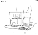
- Fig. 1 is a perspective view showing a blood analyzer according to one embodiment of the present invention.
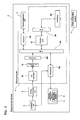
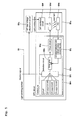
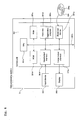
- Figs. 2 to 6 are views for describing a configuration of the blood analyzer according to one embodiment shown in Fig. 1 .
- the configuration of the blood analyzer 1 according to one embodiment of the present invention will be described with reference to Figs. 1 to 6 .
- the blood analyzer 1 is configured as a multiple automatic blood cell analyzer for performing blood test, where only the measurement of white blood cells, reticulocytes, and platelets in the blood will be described below.
- the blood analyzer 1 is configured by a measurement section 2 having a function of measuring the blood or the biological sample, and a data processing section 3 for analyzing the measurement result output from the measurement section 2 and obtaining an analysis result.
- the measurement section 2 is configured to measure the white blood cells, the reticulocytes, and the platelets in the blood through the flow cytometry method.
- the flow cytometry method used in this embodiment is a measurement method of forming a sample flow including the measurement specimen and irradiating a laser light onto the sample flow to measure the particles (blood cells) for detecting forward scattered light, lateral scattered light, and lateral fluorescence emitted by the particles (blood cells) in the measurement specimen.
- the measurement section 2 includes a device mechanism unit 4, a detection unit 5 for measuring the measurement specimen, an analog processing unit 6 on the output of the detection unit 5, a display/operation unit 7, and a microcomputer 8 for controlling the measurement section 2.
- the device mechanism unit 4 is arranged with a specimen preparation section 41 for preparing the measurement specimen from a reagent and the blood.
- the specimen preparation section 41 is arranged to prepare a white blood cell measurement specimen, a reticulocyte measurement specimen, and a platelet measurement specimen.
- the blood analyzer 1 has a plurality of measurement modes including a white blood cell differentiation measurement mode of preparing and measuring the white blood cell measurement specimen, a reticulocyte measurement mode of preparing and measuring the reticulocyte measurement specimen, and a platelet measurement mode of preparing and measuring the platelet measurement specimen. As shown in Fig.
- the specimen preparation section 41 includes a blood collection tube 41a filled with a predetermined amount of blood, a sampling valve 41b to which the blood is aspirated, and a reaction chamber 41c.
- the blood collection tube 41a is replaceable, and is configured to enable replacement of blood.
- the sampling valve 41b has a function of quantitating the blood of the blood collection tube 41a aspirated by an aspiration pipette (not shown) by a predetermined amount.
- the sampling valve 41b is configured to mix a predetermined reagent to the aspirated blood. That is, the sampling valve 41b is configured to generate a diluted sample in which a predetermined amount of reagent is mixed to a predetermined amount of blood.
- the reaction chamber 41c is configured to further mix a predetermined staining fluid to the diluted sample supplied from the sampling valve 41b and react the same for a predetermined time.
- the specimen preparation section 41 then has a function of preparing a measurement specimen in which the white blood cells are stained and the red blood cells are hemolyzed as a white blood cell measurement specimen.
- the specimen preparation section 41 also has a function of preparing the measurement specimen in which the reticulocyte is stained as the reticulocyte measurement specimen, and preparing a measurement specimen in which the platelet is stained as the platelet measurement specimen.
- the device mechanism unit 4 is configured to supply a white blood cell measurement specimen to a sheath flow cell 503 (see Fig. 4 ), to be described later, from the specimen preparation section 41 along with sheath liquid in the white blood cell differentiation measurement (hereinafter referred to as "DIFF measurement") mode.
- the device mechanism unit 4 is configured to supply the reticulocyte measurement specimen to the sheath flow cell 503 from the specimen preparation section 41 along with the sheath liquid in the reticulocyte measurement (hereinafter referred to as "RET measurement”) mode.
- the device mechanism unit 4 is configured to supply the platelet measurement specimen to the sheath flow cell 503 from the specimen preparation section 41 along with the sheath liquid in the platelet measurement (hereinafter referred to as "PLT measurement”) mode.
- the detection unit 5 includes a light emitting section 501 for irradiating a laser light, an irradiation lens unit 502, a sheath flow cell 503 to be irradiated with the laser light, a light collecting lens 504 arranged on an extending line in a direction the laser light irradiated from the light emitting section 501 advances, a pin hole 505 and a PD (photodiode) 506, a light collecting lens 507 arranged in a direction intersecting the direction the laser light irradiated from the light emitting section 501 advances, a dichroic mirror 508, an optical filter 509, a pin hole 510 and a PD 511, and an APD (avalanche photodiode) 512 arranged on the side of the dichroic mirror 508.
- a light emitting section 501 for irradiating a laser light
- an irradiation lens unit 502 for irradiating a laser light
- the light emitting section 501 is arranged to irradiate the light on the sample flow including the measurement specimen passing through the inside of the sheath flow cell 503.
- the irradiation lens unit 502 is arranged to convert the light irradiated from the light emitting section 501 to parallel light.
- the PD 506 is arranged to receive the forward scattered light irradiated from the sheath flow cell 503. Information on the size of the particle (blood cell) in the measurement specimen can be obtained by the forward scattered light irradiated from the sheath flow cell 503.
- the dichroic mirror 508 is arranged to separate the lateral scattered light and the lateral fluorescence irradiated from the sheath flow cell 503. Specifically, the dichroic mirror 508 is arranged to enter the lateral scattered light irradiated from the sheath flow cell 503 to the PD 511 and to enter the lateral fluorescence irradiated from the sheath flow cell 503 to the APD 512.
- the PD 511 is arranged to receive the lateral scattered light. Internal information such as the size of the core of the particle (blood cell) in the measurement specimen can be obtained by the lateral scattered light irradiated from the sheath flow cell 503.
- the APD 512 is arranged to receive the lateral fluorescence.
- Information on the degree of stain of the particle (blood cell) in the measurement specimen can be obtained by the lateral fluorescence irradiated from the sheath flow cell 503.
- the PDs 506, 511 and the APD 512 respectively have functions of converting the received light signal to an electrical signal.
- the light emitting section 501 is configured to irradiate light at an output of 3.4 mW in the DIFF measurement mode.
- the light emitting section 501 is configured to irradiate light at an output of 6 mW in the RET measurement mode.
- the light emitting section 501 is configured to irradiate light at an output of 10 mW in the PLT measurement mode.
- the light emitting section 501 includes a light emitting body 501a, an APC (Automatic Power Control) circuit 501b for controlling the irradiating intensity irradiated from the light emitting body 501a, and a high frequency bias voltage adjustment circuit 501c.
- APC Automatic Power Control
- the light emitting body 501a includes an LD (laser diode) 501d for irradiating light to the sample flow of the sheath flow cell 503, a PD 501e for receiving the light irradiated from the LD 501d, and a high frequency oscillation circuit 501f.
- the PD 501e has a function of converting the received light signal to an electrical signal.
- the high frequency oscillation circuit 501f is arranged to generate a signal superimposed on a' drive current supplied to the LD 501d. That is, the high frequency oscillation circuit 501f is arranged to have the light irradiated from the LD 501d in multimode in which a great number of oscillation wavelengths are present.
- the APC circuit 501b includes a drive circuit 501g for supplying the drive current to the LD 501d, and a control unit 501h for controlling the drive current supplied from the drive circuit 501g to the LD 501d.
- the control unit 501h includes a selection circuit 501i, an LD output detection unit 501j or a current-voltage conversion unit, and an error amplification unit 501k.
- a control signal from the microcomputer 8 (see Fig. 2 ) is provided to the selection circuit 501i.
- the selection circuit 501i is arranged to select the irradiating intensity irradiated from the LD 501d according to the control signal.
- the selection circuit 501i is configured to set the output of the LD 501d to 3.4 mW in the DIFF measurement mode.
- the selection circuit 501i is configured to set the output of the LD 501d to 6 mW in the RET measurement mode.
- the selection circuit 501i is configured to set the output of the LD 501d to 10 mW in the PLT measurement mode.
- the selection circuit 501i is configured to set the LD 501d in the OFF state other than in the measurement modes.
- the LD output detection unit 501j is arranged to detect the irradiating intensity irradiated from the LD 501d based on the electrical signal output from the PD 501e.
- the error amplification unit 501k is arranged to compare the irradiating intensity irradiated from the LD 501d detected by the LD output detection unit 501j and the irradiating intensity selected by the selection circuit 501i, and control the drive circuit 501g so that the irradiating intensity irradiated from the LD 501d approaches the irradiating intensity selected by the selection circuit 501i.
- the control signal from the microcomputer 8 (see Fig. 2 ) is provided to the high frequency bias voltage adjustment circuit 501c.
- the high frequency bias voltage adjustment circuit 501c is arranged to adjust the bias voltage to be supplied to the high frequency oscillation circuit 501f according to the control signal.
- the high frequency bias voltage adjustment circuit 501c is configured so that the bias voltage becomes larger as the output of the LD 501d becomes larger.
- the analog processing unit 6 includes amplifiers 61, 62, and 63.
- the amplifiers 61, 62, and 63 are respectively arranged to perform amplification and waveform processing on the electrical signal output from the PDs 506, 511 and the APD 512.
- the microcomputer 8 includes a control unit 81 with a control processor and a memory for operating the control processor, an A/D converter 82 for converting the signal output from the analog processing unit 6 to a digital signal, and a calculation unit 83 for performing a predetermined process on the digital signal output from the A/D converter 82.
- the control unit 81 has a function of controlling the device mechanism unit 4 and the detection unit 5 by way of a bus 84a and an interface 85a.
- the control unit 81 is connected to the display/operation unit 7 by way of the bus 84a and the interface 85b, and is connected to the data processing section 3 by way of a bus 84b and an interface 85c.
- the calculation unit 83 has a function of outputting the calculation result to the control unit 81 via the interface 85d and the bus 84a.
- the control unit 81 also has a function of transmitting the calculation result (measurement data) to the data processing section 3.
- the data processing section 3 is configured by a personal computer (PC), and has a function of analyzing the measurement data of the measurement section 2 and displaying the analysis result.
- the data processing section 3 includes a control unit 301, a display 302, and an input device 303.
- the control unit 301 has a function of transmitting a measurement start signal including measurement mode information and a shutdown signal to the measurement section 2.
- the control unit 301 is configured by a CPU 301a, a ROM 301b, a RAM 301c, a hard disc 301d, a read-out device 301e, an input/output interface 301f, and an image output interface 301g.
- the CPU 301a, the ROM 301b, the RAM 301c, the hard disc 301d, the read-out device 301e, the input/output interface 301f, and the image output interface 301g are connected by a bus 301h.
- the CPU 301a is arranged to execute the computer program stored in the ROM 301b and the computer program loaded in the RAM 301c.
- ROM 301b is configured by mask ROM, PROM, EPROM, EEPROM, and the like, and is recorded with the computer program to be executed by the CPU 301a, data used for the same, and the like.
- the RAM 301c is configured by SRAM, DRAM, or the like.
- the RAM 301c is used to read out the computer program recorded on the ROM 301b and the hard disc 301d. When executing such computer program, the RAM 301c is used as a work region of the CPU 301a.
- the hard disc 301d is installed with various computer programs for the CPU 301a to execute such as operating system and application program, and data used in execution of the computer programs.
- the application program 304a to be described later is also installed in the hard disc 301d.
- the read-out device 301e is configured by flexible disc drive, CD-ROM drive, DVD-ROM, or the like, and reads computer program or data recorded on a portable recording medium 304.
- the application program 304a for the computer to realize a predetermined function is stored in the portable recording medium 304, and the computer serving as the data processing section 3 reads out the application program 304a from the portable recording medium 304 and installs the application program 304a in the hard disc 301d.
- the application program 304a is not only provided by the portable recording medium 304, but also provided through the electric telecommunication line from the external equipment communicably connected to the data processing section 3 by the electric telecommunication line (wired or wireless).
- the application program 304a may be stored in the hard disc of the server computer on the Internet, and the data processing section 3 may download the application program 304a by accessing the server computer, and install the application program 304a in the hard disc 301d.
- the operating system that provides graphical user interface environment such as Windows (Registered trademark) manufactured and sold by US Microsoft Co., Ltd. is installed in the hard disc 301d.
- the application program 304a according to the present embodiment operates on the operating system.
- the input/output interface 301f is configured by serial interface such as USB, IEEE1394, RS-232C; parallel interface such as SCSI, IDE, IEEE1284; analog interface including D/A converter, A/D converter and the like.
- the input device 303 including keyboard and mouse is connected to the input/output interface 301f, so that the user can use the input device 303 to input data to the data processing section 3.
- the input device 303 is used to input specification of the measurement mode. Specifically, the user uses the input device 303 to specify whether or not to perform each of the DIFF measurement, the RET measurement, and the PLT measurement on a predetermined blood, and the control unit 301 accepts the result of specification.
- the image output interface 301g is connected to the display 302 configured by LCD, CRT, or the like, and outputs an image signal corresponding to the image data provided from the CPU 301a to the display 302.
- the display 302 displays the image (screen) according to the input image signal.
- Fig. 7 is a flowchart describing the blood analyzing operation of the blood analyzer according to one embodiment of the present invention.
- the blood analyzing operation of the blood analyzer 1 according to one embodiment of the present invention will be described with reference to Figs. 1 to 3 , 6 , and 7 .
- step S2 the control unit 81 (see fig. 2 ) is initialized and the operation check of each unit of the measurement section 2 is performed. The process thereafter proceeds to step S2.
- step S21 of Fig. 7 the control unit 301 (see Fig. 6 ) is initialized (initialization of program).
- the menu screen (not shown) is displayed on the display 302 (see Fig. 1 ) by the control unit 301.
- the menu screen is a screen for the user to select whether or not to set each of the DIFF measurement mode, the RET measurement mode, and the PLT measurement mode. Options corresponding to each of the DIFF measurement mode, the RET measurement mode, and the PLT measurement mode are displayed on the menu screen.
- the user selects arbitrary one or a plurality of options from the above options using the input device 303.
- the measurement mode to be executed on the blood sample to be analyzed is specified.
- the menu screen is a screen for accepting measurement start instruction and shutdown instruction from the user.
- step S22 determination is made on whether or not the input (specification) of the measurement mode is accepted by the control unit 301. If determined that the input of the measurement mode is accepted by the control unit 301, setting change of the measurement mode is performed by the control unit 301 in step S23. Specifically, the measurement mode accepted by the input device 303 (see Fig. 1 ) is set. If determined that the input of the measurement mode is accepted by the control unit 301, the process proceeds to step S24.
- step S24 determination is made on whether or not the measurement start instruction is accepted by the control unit 301. If determined that the measurement start instruction is accepted by the control unit 301, the process proceeds to step S25. If determined that the measurement start instruction is not accepted by the control unit 301, the process proceeds to step S31. In step S25, the measurement start signal including the measurement mode information is transmitted to the measurement section 2 by the control unit 301. The process thereafter proceeds to step S26.
- step S2 determination is made on whether or not the measurement start signal from the data processing section 3 is received by the control unit 81 in step S2. If determined that the measurement start signal is received by the control unit 81, the process proceeds to step 3. If determined that the measurement start signal is not received by the control unit 81; the process proceeds to step S13.
- step S3 the measurement mode in the measurement start information is stored by the control unit 81. Specifically, whether or not the DIFF measurement mode, the RET measurement mode, and the PLT measurement mode is set is stored.
- step S4 the blood for the set measurement mode is aspirated. Specifically, the blood in the blood collection tube 11 (see fig. 3 ) is aspirated to the sampling valve 12 (see Fig. 3 ) by the aspiration pipette.
- step S5 the measurement specimen for the set measurement mode is prepared. Specifically, a predetermined reagent is supplied to the sampling valve 12, whereby a predetermined amount of blood and a predetermined amount of reagent are mixed to produce diluted sample.
- the diluted sample is then supplied to the reaction chamber 13 (see Fig. 3 ), and a predetermined amount of staining fluid is supplied to the reaction chamber 13.
- the diluted sample and the staining fluid are then mixed and reacted for a predetermined time.
- the measurement specimen corresponding to each measurement mode is thereby prepared from one blood sample contained in the blood collecting tube 11. For instance, when all the measurement modes of the DIFF measurement, the RET measurement, and the PLT measurement are set for the analysis on the blood sample contained in the blood collecting tube 11, the blood necessary for preparing the measurement specimen of each measurement mode is divided from the blood contained in the blood collecting tube 11, and the divided blood is mixed with the predetermined reagent and the staining fluid to prepare the measurement specimen for each measurement mode measurement.
- step S6 determination is made on whether or not the DIFF measurement mode is set by the control unit 81. If determined that the DIFF measurement mode is set by the control unit 81, the DIFF measurement is performed in step S7. The operation of the DIFF measurement will be described later in detail. If determined that the DIFF measurement mode is not set by the control unit 81, the process proceeds to step S8.
- step S8 determination is made on whether or not the RET measurement mode is set by the control unit 81. If determined that the RET measurement mode is set by the control unit 81, the RET measurement is performed in step S9. The operation of the RET measurement will be described later in detail. If determined that the RET measurement mode is not set by the control unit 81, the process proceeds to step S10.
- step S10 determination is made on whether or not the PLT measurement mode is set by the control unit 81. If determined that the PLT measurement mode is set by the control unit 81, the PLT measurement is performed in step S11. The operation of the PLT measurement will be described later in detail. If determined that the PLT measurement mode is not set by the control unit 81, the process proceeds to step S12.
- step S12 the measurement result (measurement data) of the set measurement mode is transmitted to the data processing section 3 via the bus 84b (see Fig. 3 ) and the interface 85c (see Fig. 3 ) by the control unit 81. The process thereafter proceeds to step S13.
- step S26 determination is made on whether or not the measurement result (measurement data) is received from the measurement section 2 by the control unit 301 in step S26. If determined that the measurement data is received by the control unit 301, the process proceeds to step S27. If determined that the measurement data is not received by the control unit 301, step S26 is repeated until determined that the measurement data is received.
- step S27 the received measurement data is stored in the hard disc 301d (see Fig. 6 ) by the CPU 301a (see Fig. 6 ). Thereafter, in step S28, the measurement data is read out to the RAM 301c (see Fig. 6 ) by the CPU 301a. In step S29, the measurement data read out to the RAM 301c is performed with analyzing process by the CPU 301a. In step S30, the analyzing processed data is output to the display 302 via the image output interface 301g by the CPU 301a.
- the analyzing process of classifying and counting the lymphocytes, the monocytes, the neutrophils, the basophils, and the eosinophils in the blood is performed, and thereafter a scattergram as shown in Fig. 8 is displayed.
- the RET measurement is performed in step S9
- the analyzing process of classifying and counting the reticulocyte in the blood is performed, and thereafter a scattergram as shown in Fig. 9 is displayed.
- the PLT measurement is performed in step S11
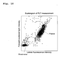
- the analyzing process of classifying and counting the platelet in the blood is performed, and thereafter, a scattergram as shown in Fig. 10 is displayed.
- the measurement result measured with the irradiating intensity suited to each measuring target can be visibly recognized by the user in each measurement mode.
- step S31 determination is made on whether or not the shutdown instruction is accepted by the control unit 301. If determined that the shutdown instruction is accepted by the control unit 301, the shutdown signal is transmitted to the measurement section 2 in step S32, and the process is terminated. If determined that the shutdown instruction is not accepted by the control unit 301, the process returns to step S22.
- step S13 determination is made on whether or not the shutdown signal is received from the data processing section 3 by the control unit 81. If determined that the shutdown signal is received by the control unit 81, the measurement section 2 is shutdown in step S14, and the process is terminated. If determined that the shutdown signal is not received by the control unit 81 in step S13, the process returns to step S2.
- Fig. 11 is a flowchart for describing the operation in the DIFF measurement of the blood analyzer according to one embodiment of the present invention. The details of the DIFF measurement of step S7 shown in Fig. 7 will be described with reference to Figs. 2 , 4 , 5 , and 11 .
- step S41 of Fig. 11 the output of the LD501d (see Fig. 5 ) is set to 3.4 mW by the control unit 81 (see Fig. 2 ).
- step S42 the laser light is irradiated on the sheath flow cell 503 (see Fig. 4 ).
- the control signal is provided from the control unit 81 to the selection circuit 501i (see Fig. 5 ).
- the control unit 501h controls the drive circuit 501g (see Fig. 5 ) to output the drive current of having the output of the LD 501d to 3.4 mW.
- a predetermined bias voltage is supplied to the high frequency oscillation circuit 501f by providing the control signal from the control unit 81 to the high frequency bias voltage adjustment circuit 501c.
- the signal corresponding to the drive current is superimposed from the high frequency oscillation circuit 501f on the drive current output from the drive circuit 501g.
- step S43 the white blood cell measurement specimen is supplied with the sheath liquid to the sheath flow cell 503 by the control unit 81.
- step S44 the counting is started by the control unit 81.
- laser light is irradiated on the white blood cells passing through the sheath flow cell. 503
- the forward,scattered light, the lateral scattered light, and the lateral fluorescence are emitted from the white blood cells.
- the lateral scattered light and the lateral fluorescence emitted from the white blood cells are respectively received by the PD 511 and the APD 512 (see Fig. 4 ), and converted to an analog electrical signal.
- the electrical signal of the lateral scattered light and the electrical signal of the lateral fluorescence are respectively transmitted to the A/D converter 82 (see Fig. 2 ) through the amplifiers 62 and 63 (see Fig. 4 ).
- step S45 the characteristic parameter of the lateral scattered light and the lateral fluorescence is acquired by the calculation unit 83 (see Fig. 2 ).
- step S46 determination is made on whether or not a predetermined time has elapsed from the start of counting by the control unit 81. If determined that the predetermined time has not elapsed from the start of counting by the control unit 81, the process returns to step S45. That is, the operation of step S45 is repeatedly performed until the predetermined time has elapsed from the start of counting. If determined that the predetermined time has elapsed from the start of counting in step S46, irradiation of the laser light is stopped in step S47.
- control signal is provided from the control unit 81 to the selection circuit 501i, whereby the control unit 501h controls the drive circuit 501g to turn OFF the LD 501d. That is, the drive current supplied from the drive circuit 501g to the LD 501d is stopped by the control unit 501h.
- step S48. supply of white blood cell measurement specimen is stopped.
- step S49 the sheath flow cell 503 is washed.
- Fig. 12 is a flowchart for describing the operation in the RET measurement of the blood analyzer according to one embodiment of the present invention. The details of the RET measurement of step S9 shown in Fig. 7 will be described with reference to Figs. 2 , 4 , 5 , and 12 .
- step S51 of Fig. 12 the output of the LD501d (see Fig. 5 ) is set to 6 mW by the control unit 81 (see Fig. 2 ).
- step S52 the laser light is irradiated on the sheath flow cell 503 (see Fig. 4 ).
- the control signal is provided from the control unit 81 to the selection circuit 501i (see Fig. 5 ).
- the control unit 501h controls the drive circuit 501g (see Fig. 5 ) to output the drive current of having the output of the LD 501d to 6 mW.
- a predetermined bias voltage is supplied to the high frequency oscillation circuit 501f by providing the control signal from the control unit 81 to the high frequency bias voltage adjustment circuit 501c.
- the signal corresponding to the drive current is superimposed from the high frequency oscillation circuit 501f on the drive current output from the drive circuit 501g.
- step S53 the reticulocyte measurement specimen is supplied with the sheath liquid to the sheath flow cell 503 by the control unit 81.
- step S54 the counting is started by the control unit 81.
- the forward scattered light, the lateral scattered light, and the lateral fluorescence are emitted from the reticulocyte.
- the forward scattered light and the lateral fluorescence emitted from the reticulocyte are respectively received by the PD 506 and the APD 512 (see Fig. 4 ), and converted to an analog electrical signal.
- the electrical signal of the forward scattered light and the electrical signal of the lateral fluorescence are respectively transmitted to the A/D converter 82 (see Fig. 2 ) through the amplifiers 61 and 63 (see Fig. 4 ).
- step S55 the characteristic parameter of the forward scattered light and the lateral fluorescence is acquired by the calculation unit 83 (see Fig. 2 ).
- step S56 determination is made on whether or not a predetermined time has elapsed from the start of counting by the control unit 81. If determined that the predetermined time has not elapsed from the start of counting by the control unit 81, the process returns to step S55. That is, the operation of step S55 is repeatedly performed until the predetermined time has elapsed from the start of counting. If determined that the predetermined time has elapsed from the start of counting in step S56, irradiation of the laser light is stopped in step S57.
- control signal is provided from the control unit 81 to the selection circuit 501i, whereby the control unit 501h controls the drive circuit 501g to turn OFF the LD 501d. That is, the drive current supplied from the drive circuit 501g to the LD 501d is stopped by the control unit 501h.
- step S58 supply of reticulocyte measurement specimen is stopped. Thereafter, in step 559,' the sheath flow cell 503 is washed.
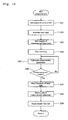
- Fig. 13 is a flowchart for describing the operation in the PLT measurement of the blood analyzer according to one embodiment of the present invention. The details of the PLT measurement of step S11 shown in Fig. 7 will be described with reference to Figs. 2 , 4 , 5 , and 13 .
- step S61 of Fig. 13 the output of the LD501d (see Fig. 5 ) is set to 10 mW by the control unit 81 (see Fig. 2 ).
- step S62 the laser light is irradiated on the sheath flow cell 503 (see Fig. 4 ).
- the control signal is provided from the control unit 81 to the selection circuit 501i (see Fig. 5 ).
- the control unit 501h controls the drive circuit 501g (see Fig. 5 ) to output the drive current of having the output of the LD 501d to 10 mW.
- a predetermined bias voltage is supplied to the high frequency oscillation circuit 501f by providing the control signal from the control unit 81 to the high frequency bias voltage adjustment circuit 501c.
- the signal corresponding to the drive current is superimposed from the high frequency oscillation circuit 501f on the drive current output from the drive circuit 501g.
- step S63 the platelet measurement specimen is supplied with the sheath liquid to the sheath flow cell 503 by the control unit 81.
- step S64 the counting is started by the control unit 81.
- the forward scattered light, the lateral scattered light, and the lateral fluorescence are emitted from the platelet.
- the forward scattered light and the lateral fluorescence emitted from the platelet are respectively received by the PD 506 and the APD 512 (see Fig. 4 ), and converted to an analog electrical signal.
- the electrical signal of the forward scattered light and the electrical signal of the lateral fluorescence are respectively transmitted to the A/D converter 82 (see Fig. 2 ) through the amplifiers 61 and 63 (see Fig. 4 ).
- step S65 the characteristic parameter of the forward scattered light and the lateral fluorescence is acquired by the calculation unit 83 (see Fig. 2 ).
- step S66 determination is made on whether or not a predetermined time has elapsed from the start of counting by the control unit 81. If determined that the predetermined time has not elapsed from the start of counting by the control unit 81, the process returns to step S65. That is, the operation of step S65 is repeatedly performed until the predetermined time has elapsed from the start of counting. If determined that the predetermined time has elapsed from the start of counting in step S66, irradiation of the laser light is stopped in step S67.
- control signal is provided from the control unit 81 to the selection circuit 501i, whereby the control unit 501h controls the drive circuit 501g to turn OFF the LD 501d. That is, the drive current supplied from the drive circuit 501g to the LD 501d is stopped by the control unit 501h.
- step S68 supply of platelet measurement specimen is stopped.
- step S69 the sheath flow cell 503 is washed.
- the irradiating intensity is adjusted according to the measurement mode by the selection circuit 501i by arranging the selection circuit 501i for selecting the irradiating intensity to be irradiated from the LD501d, as described above.
- the irradiating intensity is set to 3.4 mW in the DIFF measurement, the irradiating intensity is set to 10 mW in the PLT measurement, and the accuracy is enhanced in both the DIFF measurement and the PLT measurement.
- the blood analyzer lo f the present embodiment is an analyzer in which the irradiating intensity can be adjusted according to the measurement target. Specifically, the irradiating intensity is made small when measuring large particles such as white blood cells, and the irradiating intensity is made large when measuring small particles such as platelet. The measurement accuracy of small particles then can be enhanced while suppressing the measurement of large particles from becoming difficult.
- whether or not to perform the DIFF measurement, the RET measurement, and the PLT measurement can be easily accepted by arranging the input device 303 for accepting the measurement mode.
- the drive current corresponding to the irradiating intensity selected by the selection circuit 501i is supplied from the drive circuit 501g to the LD 501d by the control unit 501h by arranging the drive circuit 501g for supplying the drive current to the LD 501d and the control unit 501h for controlling the drive circuit 501g, whereby the irradiating intensity can be easily adjusted according to the measurement mode. If irradiation of light from the LD 501d is not necessary, the irradiation of the laser light from the LD 501d can be stopped, and the lifetime of the LD 501d can be extended.
- control unit 501h is configured to compare the irradiating intensity selected by the selection circuit 501i and the irradiating intensity irradiated from the LD 501d, and to control the drive circuit 501g so that the irradiating intensity irradiated from the LD 501d approaches the irradiating intensity selected by the selection circuit 501i, so that the irradiating intensity irradiated from the LD 501d approaches the irradiating intensity selected by the selection circuit 501i when the irradiating intensity irradiated from the LD 501d differs from the irradiating intensity selected by the selection circuit 501i due to environment temperature etc. Therefore, variation is suppressed from occurring in the irradiating intensity irradiated from the LD 501d and the irradiating intensity selected by the selection circuit 501i, and thus the measurement accuracy is suppressed from lowering.
- the drive current supplied from the drive circuit 501g to the LD 501d is adjusted based on the irradiating intensity irradiated from the LD 501d detected by the LD output detection unit 501i by arranging the PD 501e for receiving the laser light irradiated from the LD 501d and converting the same to the electrical signal and the LD output detection unit 501j for detecting the irradiating intensity irradiated from the LD 501d based on the electrical signal output from the PD 501e, and thus the irradiating intensity irradiated from the LD 501d can be easily approached to the irradiating intensity selected by the selection circuit 501i.
- the signal to be superimposed on the drive current by the high frequency oscillation circuit 501f can be adjusted according to the selected irradiating intensity by the high frequency bias voltage adjustment circuit 501c by arranging the high frequency oscillation circuit 501f for generating the signal to be superimposed on the drive current supplied to the LD 501d and the high frequency bias voltage adjustment circuit 501c for adjusting the bias voltage to supply to the high frequency oscillation circuit 501f according to the irradiating intensity selected by the selection circuit 501i, and thus the light irradiated from the LD 501d is in multimode including a great number of oscillation wavelengths regardless of the selected irradiating intensity.
- the analyzer having urine as the biological sample includes a device of measuring, classifying, and counting particle components such as bacteria, red blood cells, white blood cells, casts, and epidermal cells in the urine through the flow cytometry method.
- the particles in the urine differ in size depending on the type of particles, and thus the intensity of the light to be irradiated on the particles is changed according to the type of particles to be measured.
- the present invention is not limited thereto, and whether or not to perform the DIFF measurement, the RET measurement, and the PLT measurement may be accepted through an electrical communication line from the server computer etc.
- the selection circuit 501i for selecting the output of the LD 501d by controlling the drive current to be supplied to the LD 501d is described, but the present invention is not limited thereto, and the selection circuit for selecting the output of the LD may be arranged by arranging a predetermined neutral density filter on the path of the laser light.
- the present invention is not limited thereto, and the measurement section and the data processing section may be configured as an integrated device.
- the present invention is not limited thereto, and the output of the LD may be set to other values.
Landscapes
- Chemical & Material Sciences (AREA)
- Biochemistry (AREA)
- Physics & Mathematics (AREA)
- Health & Medical Sciences (AREA)
- Life Sciences & Earth Sciences (AREA)
- Analytical Chemistry (AREA)
- Dispersion Chemistry (AREA)
- General Health & Medical Sciences (AREA)
- General Physics & Mathematics (AREA)
- Immunology (AREA)
- Pathology (AREA)
- Investigating Or Analysing Biological Materials (AREA)
- Investigating Or Analysing Materials By Optical Means (AREA)
- Investigating, Analyzing Materials By Fluorescence Or Luminescence (AREA)
Applications Claiming Priority (1)
| Application Number | Priority Date | Filing Date | Title |
|---|---|---|---|
| JP2007086957A JP4861874B2 (ja) | 2007-03-29 | 2007-03-29 | 分析装置 |
Publications (3)
| Publication Number | Publication Date |
|---|---|
| EP1978349A2 true EP1978349A2 (de) | 2008-10-08 |
| EP1978349A3 EP1978349A3 (de) | 2013-07-03 |
| EP1978349B1 EP1978349B1 (de) | 2017-03-15 |
Family
ID=39540571
Family Applications (1)
| Application Number | Title | Priority Date | Filing Date |
|---|---|---|---|
| EP08006060.1A Not-in-force EP1978349B1 (de) | 2007-03-29 | 2008-03-28 | Blutprobenanalysator |
Country Status (4)
| Country | Link |
|---|---|
| US (1) | US7981662B2 (de) |
| EP (1) | EP1978349B1 (de) |
| JP (1) | JP4861874B2 (de) |
| CN (2) | CN102608017B (de) |
Families Citing this family (16)
| Publication number | Priority date | Publication date | Assignee | Title |
|---|---|---|---|---|
| EP4027130B1 (de) * | 2007-02-01 | 2022-11-02 | Sysmex Corporation | Probenanalysator |
| JP5441466B2 (ja) * | 2009-03-24 | 2014-03-12 | シスメックス株式会社 | 動物用血球測定装置 |
| JP5670052B2 (ja) * | 2009-03-26 | 2015-02-18 | シスメックス株式会社 | 血液分析装置、血液分析方法及びコンピュータプログラム |
| CN102087198A (zh) * | 2010-11-18 | 2011-06-08 | 苏州生物医学工程技术研究所 | 一种流式细胞仪 |
| CN102095686A (zh) * | 2010-12-21 | 2011-06-15 | 无锡荣兴科技有限公司 | 一种蓝藻的检测分析方法 |
| EP2702133B1 (de) * | 2011-04-29 | 2017-08-23 | Becton Dickinson and Company | Zellsortiersystem und -verfahren |
| US9746412B2 (en) | 2012-05-30 | 2017-08-29 | Iris International, Inc. | Flow cytometer |
| CN103048441B (zh) * | 2012-12-21 | 2014-08-20 | 深圳市锦瑞电子有限公司 | 血细胞分析仪的电路布置方法及该电路 |
| JP5877810B2 (ja) * | 2013-03-26 | 2016-03-08 | シスメックス株式会社 | 粒子分析装置、粒子分析装置用光学系および粒子分析装置用レンズ |
| JP5976589B2 (ja) * | 2013-03-29 | 2016-08-23 | シスメックス株式会社 | 検体分析方法及び検体分析システム |
| US9835640B2 (en) | 2015-02-13 | 2017-12-05 | Abbott Laboratories | Automated storage modules for diagnostic analyzer liquids and related systems and methods |
| CN106855515B (zh) * | 2017-01-22 | 2023-11-24 | 武汉璟泓科技股份有限公司 | 胶体金荧光定量分析一体机及其控制方法 |
| EP3789757B1 (de) * | 2018-04-28 | 2025-11-05 | Shenzhen Mindray Bio-Medical Electronics Co., Ltd. | Blutanalysegerät und analyseverfahren |
| JP7583401B2 (ja) | 2020-04-13 | 2024-11-14 | 国立大学法人大阪大学 | 血液分析装置 |
| CN114678765A (zh) * | 2020-12-24 | 2022-06-28 | 深圳市帝迈生物技术有限公司 | 一种激光器控制电路、样本检测方法及样本检测装置 |
| US12584902B2 (en) | 2023-12-10 | 2026-03-24 | Instrumentation Laboratory Company | Acoustic separation of a test sample |
Citations (1)
| Publication number | Priority date | Publication date | Assignee | Title |
|---|---|---|---|---|
| JP2000275163A (ja) | 1999-01-21 | 2000-10-06 | Sysmex Corp | 粒子分析装置 |
Family Cites Families (21)
| Publication number | Priority date | Publication date | Assignee | Title |
|---|---|---|---|---|
| JPS59230139A (ja) * | 1983-06-13 | 1984-12-24 | Hitachi Ltd | 粒子計数装置 |
| JPS63300940A (ja) * | 1987-05-30 | 1988-12-08 | Canon Inc | 粒子解析装置 |
| US5073029A (en) * | 1990-02-16 | 1991-12-17 | Eqm Research, Inc. | Multisource device for photometric analysis and associated chromogens |
| JPH04172632A (ja) * | 1990-11-05 | 1992-06-19 | Nec Gumma Ltd | レーザ駆動装置 |
| JPH075093A (ja) * | 1993-06-16 | 1995-01-10 | Hitachi Ltd | フロー式粒子画像解析装置 |
| US5745308A (en) * | 1996-07-30 | 1998-04-28 | Bayer Corporation | Methods and apparatus for an optical illuminator assembly and its alignment |
| DE19859211C2 (de) * | 1998-12-21 | 2001-04-26 | Grimm Aerosol Technik Gmbh & C | Einrichtung und Verfahren zum Bestimmen der Korngrößenverteilung und der Gesamtkonzentration von Partikeln in einem Probengasstrom |
| US6784981B1 (en) * | 2000-06-02 | 2004-08-31 | Idexx Laboratories, Inc. | Flow cytometry-based hematology system |
| US7641856B2 (en) * | 2004-05-14 | 2010-01-05 | Honeywell International Inc. | Portable sample analyzer with removable cartridge |
| US6979570B2 (en) * | 2001-07-26 | 2005-12-27 | Sysmex Corporation | Particle analyzer and particle analyzing method |
| EP1291659A3 (de) * | 2001-09-06 | 2008-05-21 | Sysmex Corporation | Analyseautomat und seine Komponenten |
| JP2003287491A (ja) * | 2002-01-28 | 2003-10-10 | Sysmex Corp | 粒子分析装置および粒子分析方法 |
| US9429509B2 (en) * | 2002-01-28 | 2016-08-30 | Sysmex Corporation | Particle analyzer and particle analysis method |
| JP2005024472A (ja) * | 2003-07-04 | 2005-01-27 | Sysmex Corp | 幼若血小板測定装置 |
| KR100608498B1 (ko) * | 2003-07-19 | 2006-08-08 | 주식회사 디지탈바이오테크놀러지 | 미세입자 계수 장치 |
| US7002682B2 (en) * | 2004-02-13 | 2006-02-21 | Hach Ultra Analytics, Inc. | Method and apparatus for operating a laser in an extinction-type optical particle detector |
| CN1934445A (zh) * | 2004-03-18 | 2007-03-21 | 富士胶片株式会社 | 在样品检验方法中使用的分析元件 |
| CN1677109A (zh) * | 2004-03-30 | 2005-10-05 | 希森美康株式会社 | 子宫颈癌的筛选方法 |
| JP2006105905A (ja) * | 2004-10-08 | 2006-04-20 | Fuji Electric Systems Co Ltd | 微粒子測定装置 |
| US7580120B2 (en) * | 2005-04-07 | 2009-08-25 | Sysmex Corporation | Blood analyzer, sample analyzer, and flow cytometer |
| JP5025388B2 (ja) * | 2007-08-27 | 2012-09-12 | シスメックス株式会社 | 試料分析装置及び試料分析方法 |
-
2007
- 2007-03-29 JP JP2007086957A patent/JP4861874B2/ja not_active Expired - Fee Related
-
2008
- 2008-03-28 CN CN201210065059.XA patent/CN102608017B/zh active Active
- 2008-03-28 US US12/079,650 patent/US7981662B2/en active Active
- 2008-03-28 EP EP08006060.1A patent/EP1978349B1/de not_active Not-in-force
- 2008-03-28 CN CN200810084889.0A patent/CN101275898B/zh active Active
Patent Citations (1)
| Publication number | Priority date | Publication date | Assignee | Title |
|---|---|---|---|---|
| JP2000275163A (ja) | 1999-01-21 | 2000-10-06 | Sysmex Corp | 粒子分析装置 |
Also Published As
| Publication number | Publication date |
|---|---|
| US20080241911A1 (en) | 2008-10-02 |
| CN102608017B (zh) | 2014-10-29 |
| CN101275898B (zh) | 2012-05-23 |
| JP2008241672A (ja) | 2008-10-09 |
| CN102608017A (zh) | 2012-07-25 |
| EP1978349A3 (de) | 2013-07-03 |
| JP4861874B2 (ja) | 2012-01-25 |
| EP1978349B1 (de) | 2017-03-15 |
| US7981662B2 (en) | 2011-07-19 |
| CN101275898A (zh) | 2008-10-01 |
Similar Documents
| Publication | Publication Date | Title |
|---|---|---|
| EP1978349B1 (de) | Blutprobenanalysator | |
| CN101382485B (zh) | 试样分析仪及试样分析方法 | |
| US7943383B2 (en) | Apparatus and method for automatically determining the validity of white blood sample measurements based on the characteristics of optical scattering data | |
| US8790577B2 (en) | Sample analyzer | |
| JP5203889B2 (ja) | 検体分析装置及び検体分析方法 | |
| EP1953525B1 (de) | Teilchenanalysegerät und Teilchenanalyseverfahren | |
| CN101403739B (zh) | 细胞分析仪及细胞分析方法 | |
| US9322834B2 (en) | Sample analyzer, blood analyzer and displaying method | |
| EP2045595A2 (de) | Zellanalysator und Zellanalyseverfahren | |
| US20070179715A1 (en) | Analyzer, information processing device and computer program product | |
| EP2784480A2 (de) | Blutzellenanalysator und Blutzellenanalyseverfahren | |
| CN107525758A (zh) | 控制血液分析仪测定血小板的方法 | |
| CN101995456B (zh) | 检测体分析装置以及控制系统 | |
| US20090248318A1 (en) | Sample analyzer, sample analyzing method and computer program product | |
| JP5543512B2 (ja) | 試料分析装置及び試料分析方法 | |
| JP2008241644A (ja) | 粒子分析装置 |
Legal Events
| Date | Code | Title | Description |
|---|---|---|---|
| PUAI | Public reference made under article 153(3) epc to a published international application that has entered the european phase |
Free format text: ORIGINAL CODE: 0009012 |
|
| AK | Designated contracting states |
Kind code of ref document: A2 Designated state(s): AT BE BG CH CY CZ DE DK EE ES FI FR GB GR HR HU IE IS IT LI LT LU LV MC MT NL NO PL PT RO SE SI SK TR |
|
| AX | Request for extension of the european patent |
Extension state: AL BA MK RS |
|
| RIC1 | Information provided on ipc code assigned before grant |
Ipc: G01N 15/14 20060101AFI20130415BHEP |
|
| PUAL | Search report despatched |
Free format text: ORIGINAL CODE: 0009013 |
|
| AK | Designated contracting states |
Kind code of ref document: A3 Designated state(s): AT BE BG CH CY CZ DE DK EE ES FI FR GB GR HR HU IE IS IT LI LT LU LV MC MT NL NO PL PT RO SE SI SK TR |
|
| AX | Request for extension of the european patent |
Extension state: AL BA MK RS |
|
| RIC1 | Information provided on ipc code assigned before grant |
Ipc: G01N 15/14 20060101AFI20130528BHEP |
|
| 17P | Request for examination filed |
Effective date: 20131217 |
|
| RBV | Designated contracting states (corrected) |
Designated state(s): AT BE BG CH CY CZ DE DK EE ES FI FR GB GR HR HU IE IS IT LI LT LU LV MC MT NL NO PL PT RO SE SI SK TR |
|
| AKX | Designation fees paid |
Designated state(s): AT BE BG CH CY CZ DE DK EE ES FI FR GB GR HR HU IE IS IT LI LT LU LV MC MT NL NO PL PT RO SE SI SK TR |
|
| 17Q | First examination report despatched |
Effective date: 20140527 |
|
| GRAP | Despatch of communication of intention to grant a patent |
Free format text: ORIGINAL CODE: EPIDOSNIGR1 |
|
| INTG | Intention to grant announced |
Effective date: 20161026 |
|
| GRAS | Grant fee paid |
Free format text: ORIGINAL CODE: EPIDOSNIGR3 |
|
| GRAA | (expected) grant |
Free format text: ORIGINAL CODE: 0009210 |
|
| REG | Reference to a national code |
Ref country code: FR Ref legal event code: PLFP Year of fee payment: 10 |
|
| AK | Designated contracting states |
Kind code of ref document: B1 Designated state(s): AT BE BG CH CY CZ DE DK EE ES FI FR GB GR HR HU IE IS IT LI LT LU LV MC MT NL NO PL PT RO SE SI SK TR |
|
| REG | Reference to a national code |
Ref country code: CH Ref legal event code: EP Ref country code: GB Ref legal event code: FG4D |
|
| REG | Reference to a national code |
Ref country code: IE Ref legal event code: FG4D |
|
| REG | Reference to a national code |
Ref country code: AT Ref legal event code: REF Ref document number: 876073 Country of ref document: AT Kind code of ref document: T Effective date: 20170415 |
|
| REG | Reference to a national code |
Ref country code: DE Ref legal event code: R096 Ref document number: 602008049168 Country of ref document: DE |
|
| REG | Reference to a national code |
Ref country code: NL Ref legal event code: MP Effective date: 20170315 |
|
| REG | Reference to a national code |
Ref country code: LT Ref legal event code: MG4D |
|
| PG25 | Lapsed in a contracting state [announced via postgrant information from national office to epo] |
Ref country code: HR Free format text: LAPSE BECAUSE OF FAILURE TO SUBMIT A TRANSLATION OF THE DESCRIPTION OR TO PAY THE FEE WITHIN THE PRESCRIBED TIME-LIMIT Effective date: 20170315 Ref country code: NO Free format text: LAPSE BECAUSE OF FAILURE TO SUBMIT A TRANSLATION OF THE DESCRIPTION OR TO PAY THE FEE WITHIN THE PRESCRIBED TIME-LIMIT Effective date: 20170615 Ref country code: LT Free format text: LAPSE BECAUSE OF FAILURE TO SUBMIT A TRANSLATION OF THE DESCRIPTION OR TO PAY THE FEE WITHIN THE PRESCRIBED TIME-LIMIT Effective date: 20170315 Ref country code: GR Free format text: LAPSE BECAUSE OF FAILURE TO SUBMIT A TRANSLATION OF THE DESCRIPTION OR TO PAY THE FEE WITHIN THE PRESCRIBED TIME-LIMIT Effective date: 20170616 Ref country code: FI Free format text: LAPSE BECAUSE OF FAILURE TO SUBMIT A TRANSLATION OF THE DESCRIPTION OR TO PAY THE FEE WITHIN THE PRESCRIBED TIME-LIMIT Effective date: 20170315 |
|
| REG | Reference to a national code |
Ref country code: AT Ref legal event code: MK05 Ref document number: 876073 Country of ref document: AT Kind code of ref document: T Effective date: 20170315 |
|
| PG25 | Lapsed in a contracting state [announced via postgrant information from national office to epo] |
Ref country code: LV Free format text: LAPSE BECAUSE OF FAILURE TO SUBMIT A TRANSLATION OF THE DESCRIPTION OR TO PAY THE FEE WITHIN THE PRESCRIBED TIME-LIMIT Effective date: 20170315 Ref country code: SE Free format text: LAPSE BECAUSE OF FAILURE TO SUBMIT A TRANSLATION OF THE DESCRIPTION OR TO PAY THE FEE WITHIN THE PRESCRIBED TIME-LIMIT Effective date: 20170315 Ref country code: BG Free format text: LAPSE BECAUSE OF FAILURE TO SUBMIT A TRANSLATION OF THE DESCRIPTION OR TO PAY THE FEE WITHIN THE PRESCRIBED TIME-LIMIT Effective date: 20170615 |
|
| PG25 | Lapsed in a contracting state [announced via postgrant information from national office to epo] |
Ref country code: NL Free format text: LAPSE BECAUSE OF FAILURE TO SUBMIT A TRANSLATION OF THE DESCRIPTION OR TO PAY THE FEE WITHIN THE PRESCRIBED TIME-LIMIT Effective date: 20170315 |
|
| PG25 | Lapsed in a contracting state [announced via postgrant information from national office to epo] |
Ref country code: IT Free format text: LAPSE BECAUSE OF FAILURE TO SUBMIT A TRANSLATION OF THE DESCRIPTION OR TO PAY THE FEE WITHIN THE PRESCRIBED TIME-LIMIT Effective date: 20170315 Ref country code: RO Free format text: LAPSE BECAUSE OF FAILURE TO SUBMIT A TRANSLATION OF THE DESCRIPTION OR TO PAY THE FEE WITHIN THE PRESCRIBED TIME-LIMIT Effective date: 20170315 Ref country code: EE Free format text: LAPSE BECAUSE OF FAILURE TO SUBMIT A TRANSLATION OF THE DESCRIPTION OR TO PAY THE FEE WITHIN THE PRESCRIBED TIME-LIMIT Effective date: 20170315 Ref country code: SK Free format text: LAPSE BECAUSE OF FAILURE TO SUBMIT A TRANSLATION OF THE DESCRIPTION OR TO PAY THE FEE WITHIN THE PRESCRIBED TIME-LIMIT Effective date: 20170315 Ref country code: AT Free format text: LAPSE BECAUSE OF FAILURE TO SUBMIT A TRANSLATION OF THE DESCRIPTION OR TO PAY THE FEE WITHIN THE PRESCRIBED TIME-LIMIT Effective date: 20170315 Ref country code: ES Free format text: LAPSE BECAUSE OF FAILURE TO SUBMIT A TRANSLATION OF THE DESCRIPTION OR TO PAY THE FEE WITHIN THE PRESCRIBED TIME-LIMIT Effective date: 20170315 Ref country code: CZ Free format text: LAPSE BECAUSE OF FAILURE TO SUBMIT A TRANSLATION OF THE DESCRIPTION OR TO PAY THE FEE WITHIN THE PRESCRIBED TIME-LIMIT Effective date: 20170315 |
|
| REG | Reference to a national code |
Ref country code: CH Ref legal event code: PL |
|
| PG25 | Lapsed in a contracting state [announced via postgrant information from national office to epo] |
Ref country code: PL Free format text: LAPSE BECAUSE OF FAILURE TO SUBMIT A TRANSLATION OF THE DESCRIPTION OR TO PAY THE FEE WITHIN THE PRESCRIBED TIME-LIMIT Effective date: 20170315 Ref country code: IS Free format text: LAPSE BECAUSE OF FAILURE TO SUBMIT A TRANSLATION OF THE DESCRIPTION OR TO PAY THE FEE WITHIN THE PRESCRIBED TIME-LIMIT Effective date: 20170715 Ref country code: PT Free format text: LAPSE BECAUSE OF FAILURE TO SUBMIT A TRANSLATION OF THE DESCRIPTION OR TO PAY THE FEE WITHIN THE PRESCRIBED TIME-LIMIT Effective date: 20170717 |
|
| REG | Reference to a national code |
Ref country code: DE Ref legal event code: R097 Ref document number: 602008049168 Country of ref document: DE |
|
| REG | Reference to a national code |
Ref country code: IE Ref legal event code: MM4A |
|
| PLBE | No opposition filed within time limit |
Free format text: ORIGINAL CODE: 0009261 |
|
| STAA | Information on the status of an ep patent application or granted ep patent |
Free format text: STATUS: NO OPPOSITION FILED WITHIN TIME LIMIT |
|
| PG25 | Lapsed in a contracting state [announced via postgrant information from national office to epo] |
Ref country code: DK Free format text: LAPSE BECAUSE OF FAILURE TO SUBMIT A TRANSLATION OF THE DESCRIPTION OR TO PAY THE FEE WITHIN THE PRESCRIBED TIME-LIMIT Effective date: 20170315 Ref country code: MC Free format text: LAPSE BECAUSE OF FAILURE TO SUBMIT A TRANSLATION OF THE DESCRIPTION OR TO PAY THE FEE WITHIN THE PRESCRIBED TIME-LIMIT Effective date: 20170315 Ref country code: LU Free format text: LAPSE BECAUSE OF NON-PAYMENT OF DUE FEES Effective date: 20170328 |
|
| 26N | No opposition filed |
Effective date: 20171218 |
|
| REG | Reference to a national code |
Ref country code: FR Ref legal event code: PLFP Year of fee payment: 11 |
|
| PG25 | Lapsed in a contracting state [announced via postgrant information from national office to epo] |
Ref country code: IE Free format text: LAPSE BECAUSE OF NON-PAYMENT OF DUE FEES Effective date: 20170328 Ref country code: LI Free format text: LAPSE BECAUSE OF NON-PAYMENT OF DUE FEES Effective date: 20170331 Ref country code: CH Free format text: LAPSE BECAUSE OF NON-PAYMENT OF DUE FEES Effective date: 20170331 Ref country code: SI Free format text: LAPSE BECAUSE OF FAILURE TO SUBMIT A TRANSLATION OF THE DESCRIPTION OR TO PAY THE FEE WITHIN THE PRESCRIBED TIME-LIMIT Effective date: 20170315 |
|
| REG | Reference to a national code |
Ref country code: BE Ref legal event code: MM Effective date: 20170331 |
|
| PG25 | Lapsed in a contracting state [announced via postgrant information from national office to epo] |
Ref country code: BE Free format text: LAPSE BECAUSE OF NON-PAYMENT OF DUE FEES Effective date: 20170331 |
|
| PG25 | Lapsed in a contracting state [announced via postgrant information from national office to epo] |
Ref country code: MT Free format text: LAPSE BECAUSE OF NON-PAYMENT OF DUE FEES Effective date: 20170328 |
|
| PG25 | Lapsed in a contracting state [announced via postgrant information from national office to epo] |
Ref country code: HU Free format text: LAPSE BECAUSE OF FAILURE TO SUBMIT A TRANSLATION OF THE DESCRIPTION OR TO PAY THE FEE WITHIN THE PRESCRIBED TIME-LIMIT; INVALID AB INITIO Effective date: 20080328 |
|
| PG25 | Lapsed in a contracting state [announced via postgrant information from national office to epo] |
Ref country code: CY Free format text: LAPSE BECAUSE OF NON-PAYMENT OF DUE FEES Effective date: 20170315 |
|
| PG25 | Lapsed in a contracting state [announced via postgrant information from national office to epo] |
Ref country code: TR Free format text: LAPSE BECAUSE OF FAILURE TO SUBMIT A TRANSLATION OF THE DESCRIPTION OR TO PAY THE FEE WITHIN THE PRESCRIBED TIME-LIMIT Effective date: 20170315 |
|
| PGFP | Annual fee paid to national office [announced via postgrant information from national office to epo] |
Ref country code: FR Payment date: 20230208 Year of fee payment: 16 |
|
| PGFP | Annual fee paid to national office [announced via postgrant information from national office to epo] |
Ref country code: GB Payment date: 20230202 Year of fee payment: 16 Ref country code: DE Payment date: 20230131 Year of fee payment: 16 |
|
| REG | Reference to a national code |
Ref country code: DE Ref legal event code: R119 Ref document number: 602008049168 Country of ref document: DE |
|
| GBPC | Gb: european patent ceased through non-payment of renewal fee |
Effective date: 20240328 |
|
| PG25 | Lapsed in a contracting state [announced via postgrant information from national office to epo] |
Ref country code: DE Free format text: LAPSE BECAUSE OF NON-PAYMENT OF DUE FEES Effective date: 20241001 |
|
| PG25 | Lapsed in a contracting state [announced via postgrant information from national office to epo] |
Ref country code: GB Free format text: LAPSE BECAUSE OF NON-PAYMENT OF DUE FEES Effective date: 20240328 |
|
| PG25 | Lapsed in a contracting state [announced via postgrant information from national office to epo] |
Ref country code: FR Free format text: LAPSE BECAUSE OF NON-PAYMENT OF DUE FEES Effective date: 20240331 |
|
| PG25 | Lapsed in a contracting state [announced via postgrant information from national office to epo] |
Ref country code: GB Free format text: LAPSE BECAUSE OF NON-PAYMENT OF DUE FEES Effective date: 20240328 Ref country code: FR Free format text: LAPSE BECAUSE OF NON-PAYMENT OF DUE FEES Effective date: 20240331 Ref country code: DE Free format text: LAPSE BECAUSE OF NON-PAYMENT OF DUE FEES Effective date: 20241001 |