EP1978337B1 - Ultraschallzähler zur Bestimmung der Durchflussmenge eines strömenden Mediums - Google Patents
Ultraschallzähler zur Bestimmung der Durchflussmenge eines strömenden Mediums Download PDFInfo
- Publication number
- EP1978337B1 EP1978337B1 EP08009694.4A EP08009694A EP1978337B1 EP 1978337 B1 EP1978337 B1 EP 1978337B1 EP 08009694 A EP08009694 A EP 08009694A EP 1978337 B1 EP1978337 B1 EP 1978337B1
- Authority
- EP
- European Patent Office
- Prior art keywords
- deflection mirror
- housing
- ultrasound
- ultrasonic
- ultrasound meter
- Prior art date
- Legal status (The legal status is an assumption and is not a legal conclusion. Google has not performed a legal analysis and makes no representation as to the accuracy of the status listed.)
- Expired - Lifetime
Links
- 238000002604 ultrasonography Methods 0.000 title claims description 18
- 238000005259 measurement Methods 0.000 claims description 6
- 238000007789 sealing Methods 0.000 claims description 6
- 239000007788 liquid Substances 0.000 claims description 2
- 239000002184 metal Substances 0.000 description 4
- 238000013461 design Methods 0.000 description 3
- 230000007774 longterm Effects 0.000 description 3
- 238000004519 manufacturing process Methods 0.000 description 3
- 238000011144 upstream manufacturing Methods 0.000 description 3
- 230000015572 biosynthetic process Effects 0.000 description 2
- 238000010276 construction Methods 0.000 description 2
- 238000011109 contamination Methods 0.000 description 2
- 230000000694 effects Effects 0.000 description 2
- 238000010137 moulding (plastic) Methods 0.000 description 2
- XLYOFNOQVPJJNP-UHFFFAOYSA-N water Substances O XLYOFNOQVPJJNP-UHFFFAOYSA-N 0.000 description 2
- 229920000049 Carbon (fiber) Polymers 0.000 description 1
- 229920002430 Fibre-reinforced plastic Polymers 0.000 description 1
- 239000004696 Poly ether ether ketone Substances 0.000 description 1
- 229920002873 Polyethylenimine Polymers 0.000 description 1
- 229920000491 Polyphenylsulfone Polymers 0.000 description 1
- JUPQTSLXMOCDHR-UHFFFAOYSA-N benzene-1,4-diol;bis(4-fluorophenyl)methanone Chemical compound OC1=CC=C(O)C=C1.C1=CC(F)=CC=C1C(=O)C1=CC=C(F)C=C1 JUPQTSLXMOCDHR-UHFFFAOYSA-N 0.000 description 1
- 239000004917 carbon fiber Substances 0.000 description 1
- 238000005516 engineering process Methods 0.000 description 1
- 239000011151 fibre-reinforced plastic Substances 0.000 description 1
- 239000003365 glass fiber Substances 0.000 description 1
- 238000009434 installation Methods 0.000 description 1
- 238000012423 maintenance Methods 0.000 description 1
- 239000000463 material Substances 0.000 description 1
- 238000000465 moulding Methods 0.000 description 1
- 239000004033 plastic Substances 0.000 description 1
- 229920003023 plastic Polymers 0.000 description 1
- 229920003208 poly(ethylene sulfide) Polymers 0.000 description 1
- 229920002492 poly(sulfone) Polymers 0.000 description 1
- 229920006393 polyether sulfone Polymers 0.000 description 1
- 229920002530 polyetherether ketone Polymers 0.000 description 1
- 229920001601 polyetherimide Polymers 0.000 description 1
- 229920006375 polyphtalamide Polymers 0.000 description 1
- 238000012545 processing Methods 0.000 description 1
- 230000005236 sound signal Effects 0.000 description 1
- 125000006850 spacer group Chemical group 0.000 description 1
- 238000012360 testing method Methods 0.000 description 1
- 238000003260 vortexing Methods 0.000 description 1
Images


Classifications
-
- G—PHYSICS
- G01—MEASURING; TESTING
- G01F—MEASURING VOLUME, VOLUME FLOW, MASS FLOW OR LIQUID LEVEL; METERING BY VOLUME
- G01F1/00—Measuring the volume flow or mass flow of fluid or fluent solid material wherein the fluid passes through a meter in a continuous flow
- G01F1/66—Measuring the volume flow or mass flow of fluid or fluent solid material wherein the fluid passes through a meter in a continuous flow by measuring frequency, phase shift or propagation time of electromagnetic or other waves, e.g. using ultrasonic flowmeters
- G01F1/662—Constructional details
-
- G—PHYSICS
- G01—MEASURING; TESTING
- G01F—MEASURING VOLUME, VOLUME FLOW, MASS FLOW OR LIQUID LEVEL; METERING BY VOLUME
- G01F1/00—Measuring the volume flow or mass flow of fluid or fluent solid material wherein the fluid passes through a meter in a continuous flow
- G01F1/66—Measuring the volume flow or mass flow of fluid or fluent solid material wherein the fluid passes through a meter in a continuous flow by measuring frequency, phase shift or propagation time of electromagnetic or other waves, e.g. using ultrasonic flowmeters
- G01F1/667—Arrangements of transducers for ultrasonic flowmeters; Circuits for operating ultrasonic flowmeters
Definitions
- the present invention relates to an ultrasonic meter for determining the flow rate of a flowing medium, in particular liquid or gas, with an elongated housing, which is flowed through by the medium, a arranged within the housing measuring path, along which a transit time measurement, in particular differential transit time measurement, is feasible, at least an ultrasonic transducer, at least one deflection mirror which is upstream of the flowing medium, by means of which the ultrasonic wave of the ultrasonic transducer is deflected towards the measuring tube, and a Umlenkspiegelhalter is provided.
- the opposite measurement takes place either via reflection of the ultrasound signal of the ultrasound transducer or via an ultrasound signal sent by a further ultrasound transducer at the opposite end of the test section.
- the ultrasonic counter comprises an integral part which has as its integral part the same reflecting surfaces. The part is fixed by means of resilient spacers within the housing.
- the EP-A-0 392 294 describes a flow meter in which a plurality of deflection mirrors is fixed to ensure multiple reflection along the inside of the measuring tube.
- the EP-A-0 477 418 describes an ultrasonic counter, in which a reflector assembly is arranged on the bottom of a trough-shaped sheet metal construction.
- the trough-shaped sheet metal construction is preferably formed in one piece.
- the DE 195 33 814 A1 describes an ultrasonic counter with a cylindrical housing in which an annular measuring section is arranged with a plurality of arranged on the outer and inner wall of the measuring section deflecting mirror.
- the measuring section is formed by a housing insert, which comprises two identically formed, assemblable internal parts whose separating plane is oriented transversely to the housing longitudinal axis. Since the internal parts surround the ultrasonic measuring heads, the internal parts must be inserted successively into the housing.
- the DE 201 07 894 U 1 discloses an ultrasonic flowmeter of the generic type.
- the upper edge of the deflecting mirror facing away from the medium flows around, whereby a recirculation zone or zones of reduced flow velocity in the region of the surface of the first deflecting mirror form, causing contamination on the deflecting mirror. This suffers the long-term stability of the ultrasonic flowmeter.
- the DE 199 30 278 A1 describes an ultrasonic counter with a first deflection mirror, which includes aligned parallel to the flow path holes that are intended to counteract contamination of the deflection mirror.
- the deflecting mirrors described therein are very expensive in their production, since a large number of holes, which are not perpendicular to the mirror plane, must be introduced.
- the object of the present invention is to provide a novel ultrasonic meter, which is simple and inexpensive to manufacture.
- the Umlenkapthalter is composed of two separate longitudinally to the housing halves, which can be conveniently assembled along a longitudinal dividing line. This facilitates on the one hand the use of the mirror and on the other hand the production of the Umlenkapthalters as elaborately shaped plastic molding. Also, identical halves may be provided for additional deflection mirrors in the ultrasonic meter. This idea allows optimal fixation of the deflection mirror, which is an important prerequisite for ensuring a long-term stability of the ultrasonic meter.
- the Umlenkapthalter has means for fixing the measuring tube, advantageously no housing processing is necessary.
- thermal expansion coefficients of mirror holder, housing and / or mirror can be adjusted.
- the deflection mirror expediently has parallel holding surfaces. He can z. B. polygonal, in particular octagonal, whereby better fixation accuracy can be achieved during installation. The fixation of the mirror takes place here z. B. form-fitting either over the four rectangular surfaces or over the four diagonal surfaces.
- the mirror can be held positively by corresponding pockets in the holder, which increases the long-term stability.
- the holding webs on Umlenkapthalter may be formed in a sieve or as a flow straightener.
- the subject matter of claim 4 has the advantage that - due to the special fixation - a reduced tolerance of the components is possible.
- a further expedient embodiment of the present invention is characterized in that Umlenkapthalter, deflecting mirrors and
- Measuring tube as a unit out of the housing of the ultrasonic meter or in this hineinschiebbar and in particular without disassembly of the respective ultrasonic transducer. This greatly simplifies maintenance and service.
- the ultrasound transducer (s) are or are located in the housing of the ultrasound counter, for example running flush with the inner surface of the measuring tube or further offset inwards into the housing of the ultrasound counter.
- the Umlenkapthalter is surrounded by at least one, preferably two sealing rings, on the one hand cause a sealing effect of Umlenkapthalters to the housing of the ultrasonic meter, on the other hand, the unit consisting Umlenkapthalter, deflecting mirror and measuring tube together, so that it is particularly easy to handle when inserting or pulling ,
- FIG. 1 shows a generic ultrasonic meter with a housing 1, an ultrasonic transducer 2 and a further ultrasonic transducer 3, which are respectively inserted through this provided housing openings in the side wall of the housing 1 and held by associated covers with seals in the wall of the housing 1.
- the ultrasonic transducer 2 is a deflection mirror 5, the further ultrasonic transducer 3, a further deflecting mirror 6 assigned.
- the measuring section 4 (ie the path of the sound signals) runs from the ultrasonic transducer 2 to the deflection mirror 5, from the latter to the further deflection mirror 6 and from this to the further transducer 3 and from this in opposite directions.
- the measuring section 4 therefore has a U-shape.
- other mirrors (not shown) and a diagonally extending sound guide may also be present within the scope of the invention (not shown).
- the area between the two deflecting mirrors 5 and 6 of the measuring section 4 is surrounded by a measuring tube 7, which is held in the housing 1 via a measuring tube holder 9.
- the medium for. As service water flows through an inlet, not shown, in the representation of Fig. 1 from the left, flows around the deflection mirror 5, flows along the measuring section 4, flows around the further deflection mirror 6 and leaves the ultrasonic counter in the region of the (also not shown) outlet.
- the deflection mirrors 5 and 6 are each fixed by a UmlenkLitehalter 8, of which only UmlenkLitehalter 8 in the region of the deflection mirror 5 in Fig. 1 is shown.
- Fig. 2 is located in the region of Umlenkapthalters 8, a nozzle 12 for generating a partial flow, which is directed in the upper region of the surface of the first deflection mirror 5 parallel to the surface thereof.
- This partial flow prevents the formation of recirculation vortices 20 and thus a recirculation zone.
- the nozzle has a slightly curved course and extends towards the mirror surface with a continuously tapering cross section.
- the nozzle 12 is expediently flat, so that the partial flow covers a wider surface area of the deflection mirror 5.
- the Umlenkapthalter 8 is sleeve-shaped and is inserted axially into the housing 1 of the ultrasonic meter.
- the holder 8 expediently - as in Fig. 2 shown - circumferentially arranged, large-scale openings on.
- the holder of the deflecting mirror 5 opposite region of Umlenkapthalters 8 is a circumferential recess, which serves as a receptacle 10 for a in Fig. 2 not shown measuring tube holder (reference numeral 9 in Fig. 3 A) serves.
- the deflecting mirror 5 is fixed by a plurality of opposing retaining projections 13 on two mutually parallel surfaces, of which in Fig. 2 only two are shown for clarity.
- the Umlenkapthalter is suitably made of a material with a high modulus of elasticity, in particular of plastic, for.
- Fiber reinforced plastics such as PES, PSU, PPSU, PPA, PEI, PEEK / PEAK including their derivatives PPS or PPE.
- the thermal expansion of the housing typically metal can be adjusted.
- the holding webs 11 of Umlenkapthalters 8 are kept small in cross-section, for example, less than 4 mm 2 (eg., 2 x 2 mm) to keep the pressure loss at the Spiegelumströmung low and the webs acoustically neglect.
- the cross-sectional geometry of the webs of Umlenkapthalters 8 has expediently a vortexing of the medium favoring form, as will be explained in more detail later.
- the webs 11 of the Umlenkapthalters 8 - see. Fig. 6 - But also have a rectifying effect on the flow, in particular on the inlet flow.
- the webs 11 of the Umlenkapthalters 8 may alternatively be formed in a sieve-shaped.
- the in Fig. 3 A shown Umlenkapthalter 8 corresponds to the Umlenkapthalter 8 of the embodiment according to Fig. 2 , Instead of the nozzle is at the embodiment according to Fig. 3 A an arrangement of guide vanes 14 is provided. These guide vanes 14 also ensure the formation of a corresponding partial flow, which occurs directed at the upper end of the deflection mirror 5 parallel to the surface thereof.
- the Umlenkapthalter 8 of the embodiment according to Fig. 2 such as Fig. 3 formed in the form of two longitudinally cut halves, as is apparent from Fig. 3B results.
- the two halves are mirror-symmetrical to each other.
- the guide vanes 14 of each half of Umlenkapthalters 8 may be arranged as an additional part provided or integrated into the molding.
- Fig. 3 A the attachment of the measuring tube 7 via its measuring tube holder 9 and the receptacle 10 for the measuring tube holder 9 can be seen.
- Fig. 3B identical features of the two halves of Umlenkapthalters 8 are drawn only once.
- the deflection mirror 5 is octagonal and is held on corresponding retaining projections 13 which engage diametrically opposite parallel edges. As a result, a particularly secure fixation of the deflection mirror 5 is ensured.
- the first deflection mirror 5 is expediently made of a sheet metal part, which is either stamped or cut water jet.
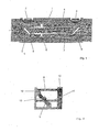
- Fig. 4 shows a further embodiment of the ultrasonic counter according to the invention in longitudinal section.
- the Umlenkapthalter 8 is formed over the entire length of the measuring section 4 molded part and includes the recording of the deflecting mirror 5, the holding webs 11 and the receptacle 10 for the measuring tube holder 9 of the measuring tube. 7 ,
- the Umlenkapthalter 8 is formed over the entire length of the measuring section 4, that carries both the one deflecting mirror 5 and the other deflection mirror 6.
- the Umlenkapthalter 8 is held by a centrally mounted fixing member 22 in position, whereby the components (due to the symmetrical fixation ) can be manufactured with a reduced tolerance.
- the deflecting mirror holder 8 receives the measuring tube 7.
- the Umlenkapthalter 8 - viewed transversely to the measuring section 4 - divided into two, so that between the two shells of UmlenkLitehalters 8 of the respective deflection mirror 5 and 6 and the measuring tube 7 is inserted and the measuring insert 25 formed thereby, see. Fig. 5 , is held together by circumferential sealing rings 23, 24.
- the measuring insert 25 can be inserted or removed in a simple manner in the housing 1 of the ultrasonic counter.
- the sealing rings 23, 24 are also used for Sealing of that portion of the measuring insert 25 to which the fixing element 22 engages.
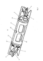
- the Umlenkapthalter 8 has, according to FIG.
- the deflection mirror holder 8 comprises a plurality of openings 28 in the area of the measuring tube 7.
- the ultrasonic transducers 2, 3 are arranged in the housing 1 of the ultrasonic counter, parallel to the flow direction. As a result, the measuring insert 25 can be pushed out of the housing 1 or pushed into it without the ultrasonic transducers 2, 3 having to be dismounted.
- FIG. 6 shows a plan view of the Umlenkapthalter 8 from the upstream view.
- the Umlenkapthalter 8 comprises two crossed holding webs 11, with which a flow rectification is achieved.
- the deflection mirror 5 is positioned in the middle region of Umlenkapthalters 8.
- a novel ultrasonic counter is provided, which is to produce in a simple and cost-effective manner.
- the invention therefore represents a very significant contribution in the relevant field of technology.
Landscapes
- Physics & Mathematics (AREA)
- Electromagnetism (AREA)
- Fluid Mechanics (AREA)
- General Physics & Mathematics (AREA)
- Investigating Or Analyzing Materials By The Use Of Ultrasonic Waves (AREA)
- Measuring Volume Flow (AREA)
Priority Applications (1)
| Application Number | Priority Date | Filing Date | Title |
|---|---|---|---|
| PL08009694T PL1978337T3 (pl) | 2003-06-13 | 2004-06-08 | Licznik ultradźwiękowy do określania przepływu płynącego medium |
Applications Claiming Priority (3)
| Application Number | Priority Date | Filing Date | Title |
|---|---|---|---|
| DE2003127076 DE10327076B3 (de) | 2003-06-13 | 2003-06-13 | Ultraschallzähler zur Bestimmung der Durchflussmenge eines strömenden Mediums |
| DE200410010408 DE102004010408A1 (de) | 2004-03-01 | 2004-03-01 | Ultraschallzähler zur Bestimmung der Durchflussmenge eines strömenden Mediums |
| EP04013456.1A EP1493998B1 (de) | 2003-06-13 | 2004-06-08 | Ultraschallzähler zur Bestimmung der Durchflussmenge eines strömenden Mediums |
Related Parent Applications (3)
| Application Number | Title | Priority Date | Filing Date |
|---|---|---|---|
| EP04013456.1A Division-Into EP1493998B1 (de) | 2003-06-13 | 2004-06-08 | Ultraschallzähler zur Bestimmung der Durchflussmenge eines strömenden Mediums |
| EP04013456.1A Division EP1493998B1 (de) | 2003-06-13 | 2004-06-08 | Ultraschallzähler zur Bestimmung der Durchflussmenge eines strömenden Mediums |
| EP04013456.1 Division | 2004-06-08 |
Publications (2)
| Publication Number | Publication Date |
|---|---|
| EP1978337A1 EP1978337A1 (de) | 2008-10-08 |
| EP1978337B1 true EP1978337B1 (de) | 2013-08-07 |
Family
ID=33435977
Family Applications (2)
| Application Number | Title | Priority Date | Filing Date |
|---|---|---|---|
| EP08009694.4A Expired - Lifetime EP1978337B1 (de) | 2003-06-13 | 2004-06-08 | Ultraschallzähler zur Bestimmung der Durchflussmenge eines strömenden Mediums |
| EP04013456.1A Expired - Lifetime EP1493998B1 (de) | 2003-06-13 | 2004-06-08 | Ultraschallzähler zur Bestimmung der Durchflussmenge eines strömenden Mediums |
Family Applications After (1)
| Application Number | Title | Priority Date | Filing Date |
|---|---|---|---|
| EP04013456.1A Expired - Lifetime EP1493998B1 (de) | 2003-06-13 | 2004-06-08 | Ultraschallzähler zur Bestimmung der Durchflussmenge eines strömenden Mediums |
Country Status (3)
| Country | Link |
|---|---|
| EP (2) | EP1978337B1 (da) |
| DK (2) | DK1978337T3 (da) |
| PL (2) | PL1493998T3 (da) |
Cited By (2)
| Publication number | Priority date | Publication date | Assignee | Title |
|---|---|---|---|---|
| DE102014019424A1 (de) | 2014-12-20 | 2016-06-23 | Diehl Metering Gmbh | Ultraschallzähler |
| EP3139138A1 (de) | 2015-09-04 | 2017-03-08 | Landis+Gyr GmbH | Messarmatur für einen durchflussmesser |
Families Citing this family (15)
| Publication number | Priority date | Publication date | Assignee | Title |
|---|---|---|---|---|
| DK1701140T3 (da) * | 2005-03-11 | 2013-02-04 | Landis & Gyr Gmbh | Ultralydsmålekanal |
| EP1798528B1 (de) * | 2005-12-16 | 2012-08-08 | Hans-Holger Körner | Durchflussmengenmesseinrichtung für fluide Medien |
| US8878690B2 (en) | 2009-06-23 | 2014-11-04 | Badger Meter, Inc. | AMR transmitter and method using multiple radio messages |
| DE202009014502U1 (de) * | 2009-10-27 | 2011-03-10 | Körner, Hans-Holger | Durchflussmengenmesseinrichtung mit Spiegel am Messrohrende |
| DK2423648T3 (da) | 2010-08-31 | 2016-01-11 | Kamstrup As | Ultrasonisk flowmåler med indsats fastholdt af en låsefinger |
| US8482908B2 (en) | 2011-10-14 | 2013-07-09 | Badger Meter, Inc. | Electronic meter register and method having a bottom formed by sealing material |
| CN102637046A (zh) * | 2012-04-23 | 2012-08-15 | 江苏迈拓智能仪表有限公司 | 一种超声计量和流量控制系统 |
| EP2888560B1 (en) * | 2012-08-22 | 2023-06-28 | Apator Miitors ApS | A compact ultrasonic flow meter |
| DE202012104853U1 (de) | 2012-12-13 | 2013-01-04 | Engelmann Sensor Gmbh | Durchflussmengenmesser zur Bestimmung der Durchflussmenge eines Fluids |
| DE102013219907A1 (de) | 2013-10-01 | 2015-04-02 | Landis+Gyr Gmbh | Messeinsatz für einen Durchflussmesser und Verfahren zu dessen Herstellung |
| EP4089374B1 (en) * | 2014-07-21 | 2025-09-03 | Apator Miitors ApS | Flow conduit insert for an ultrasonic flowmeter |
| EP3347682B1 (en) * | 2015-09-09 | 2020-06-24 | Danfoss A/S | Two part reflector holder for an ultrasonic flow sensor |
| DE102016008302A1 (de) | 2016-07-06 | 2018-01-11 | Diehl Metering Gmbh | Ultraschallzähler zur Erfassung einer Durchflussmenge eines Fluids |
| CN107255497B (zh) * | 2017-04-25 | 2023-08-15 | 中国计量大学 | 一种超声波水表反射片擦洗装置 |
| DE102017010282B4 (de) * | 2017-09-09 | 2022-04-21 | Diehl Metering Gmbh | Durchflusszähler und Verfahren zur Herstellung eines Durchflusszählers |
Family Cites Families (13)
| Publication number | Priority date | Publication date | Assignee | Title |
|---|---|---|---|---|
| US4610167A (en) | 1984-07-23 | 1986-09-09 | Westinghouse Electric Corp. | Apparatus for measuring flow velocity of fluids |
| EP0392294A1 (de) | 1989-04-13 | 1990-10-17 | Siemens Aktiengesellschaft | Durchflussmesseinrichtung für flüssige Medien nach dem Ultraschall-Laufzeitprizip |
| DE59010261D1 (de) | 1990-09-28 | 1996-05-09 | Siemens Ag | Ultraschall (US)-Durchflussmesser-Einbaueinheit zum Einbauen in ein Messrohr |
| US5043706A (en) * | 1990-10-19 | 1991-08-27 | Eastman Kodak Company | System and method for detecting bubbles in a flowing fluid |
| EP0559938B1 (de) * | 1992-03-11 | 1993-10-27 | Siemens Aktiengesellschaft | Durchflussmesseinrichtung für flüssige Medien nach dem Ultraschall-Laufzeitprinzip |
| DK9400174Y6 (da) * | 1994-04-14 | 1994-07-22 | Kamstrup As | Strømningsmåler til måling af en fluidumstrøm gennem en strømningskanal |
| DE19533814C2 (de) | 1995-09-13 | 1999-11-18 | Iwk Regler Kompensatoren | Vorrichtung zur Ultraschall-Durchflußmessung |
| DK0897102T3 (da) * | 1997-08-14 | 2007-10-29 | Landis & Gyr Gmbh | Ultralyd-gennemströmningsmåler |
| DE19930278C2 (de) * | 1999-07-01 | 2001-09-06 | Hydrometer Gmbh | Ultraschallzähler mit Schallumlenkung |
| DE19944411A1 (de) * | 1999-09-16 | 2001-04-12 | Kundo Systemtechnik Gmbh | Ultraschall-Durchflußmesser |
| DE10047383C1 (de) * | 2000-09-25 | 2001-11-08 | Siemens Ag | Ultraschall-Durchflussmesser |
| DE10109161B4 (de) * | 2001-02-24 | 2005-01-20 | Hydrometer Gmbh | Durchflußmesser |
| DK200100101U3 (da) | 2001-04-11 | 2001-05-25 | Kamstrup As | Ultralydsflowmåler |
-
2004
- 2004-06-08 PL PL04013456T patent/PL1493998T3/pl unknown
- 2004-06-08 DK DK08009694.4T patent/DK1978337T3/da active
- 2004-06-08 PL PL08009694T patent/PL1978337T3/pl unknown
- 2004-06-08 EP EP08009694.4A patent/EP1978337B1/de not_active Expired - Lifetime
- 2004-06-08 DK DK04013456.1T patent/DK1493998T3/da active
- 2004-06-08 EP EP04013456.1A patent/EP1493998B1/de not_active Expired - Lifetime
Cited By (4)
| Publication number | Priority date | Publication date | Assignee | Title |
|---|---|---|---|---|
| DE102014019424A1 (de) | 2014-12-20 | 2016-06-23 | Diehl Metering Gmbh | Ultraschallzähler |
| DE102014019424B4 (de) * | 2014-12-20 | 2016-07-21 | Diehl Metering Gmbh | Ultraschallzähler |
| EP3139138A1 (de) | 2015-09-04 | 2017-03-08 | Landis+Gyr GmbH | Messarmatur für einen durchflussmesser |
| DE102015217024A1 (de) | 2015-09-04 | 2017-03-09 | Landis + Gyr Gmbh | Messarmatur für einen Durchflussmesser |
Also Published As
| Publication number | Publication date |
|---|---|
| EP1493998A3 (de) | 2007-02-21 |
| EP1493998B1 (de) | 2016-11-02 |
| DK1493998T3 (da) | 2017-02-13 |
| PL1493998T3 (pl) | 2017-06-30 |
| EP1978337A1 (de) | 2008-10-08 |
| PL1978337T3 (pl) | 2014-01-31 |
| EP1493998A2 (de) | 2005-01-05 |
| DK1978337T3 (da) | 2013-11-04 |
Similar Documents
| Publication | Publication Date | Title |
|---|---|---|
| EP1978337B1 (de) | Ultraschallzähler zur Bestimmung der Durchflussmenge eines strömenden Mediums | |
| EP2172657B1 (de) | Strömungsrichter für ein Durchflussmessgerät, insbesondere ein Ultraschallmessgerät | |
| EP1975574B1 (de) | Durchflussmesser | |
| EP1890115B1 (de) | Ultraschalldurchflussmesser | |
| DE102011112028B4 (de) | Ultraschallzähler | |
| DE102004010408A1 (de) | Ultraschallzähler zur Bestimmung der Durchflussmenge eines strömenden Mediums | |
| EP2625492B1 (de) | Coriolis-massedurchflussmessgerät | |
| EP1876427A1 (de) | Ultraschall-durchflussmesser mit einer tubulatorkomponente im einlaufbereich | |
| EP1891400A1 (de) | Ultraschallmessstrecke aus kunststoff und entsprechendes messverfahren | |
| DE10327076B3 (de) | Ultraschallzähler zur Bestimmung der Durchflussmenge eines strömenden Mediums | |
| EP1227303B1 (de) | Ultraschalldurchflusszähler mit einer austauschbaren Messstrecke | |
| DE102013012139A1 (de) | Ultraschallzähler | |
| DE4415889A1 (de) | Meßwertgeber zur Messung von Flüssigkeitsströmungen mit Ultraschall | |
| EP1798528B1 (de) | Durchflussmengenmesseinrichtung für fluide Medien | |
| EP3599446B1 (de) | Ultraschallzähler | |
| EP0897102A1 (de) | Ultraschall-Durchflussmesser | |
| EP2172654B1 (de) | Kreiselpumpenaggregat | |
| EP2317288A1 (de) | Durchflussmengenmesseinrichtung mit Spiegel am Messrohrende | |
| DE102005015150A1 (de) | Maschinengehäuse | |
| DE102015014697B3 (de) | Coriolis-Massendurchflussmessgerät | |
| DE102017130346A1 (de) | Durchflussmesseinrichtung sowie Laminar-Strömungselement | |
| DE102004053860B4 (de) | Ultraschallzähler zur Bestimmung der Durchflussmenge eines strömenden Mediums | |
| EP1255094A2 (de) | Anordnung zur Messung der Fliessgeschwindigkeit eines Mediums | |
| DE10240975B4 (de) | Meßwertgeber für einen Ultraschall-Durchflussmesser | |
| DE102005062628B3 (de) | Ultraschallzähler |
Legal Events
| Date | Code | Title | Description |
|---|---|---|---|
| PUAI | Public reference made under article 153(3) epc to a published international application that has entered the european phase |
Free format text: ORIGINAL CODE: 0009012 |
|
| 17P | Request for examination filed |
Effective date: 20080528 |
|
| AC | Divisional application: reference to earlier application |
Ref document number: 1493998 Country of ref document: EP Kind code of ref document: P |
|
| AK | Designated contracting states |
Kind code of ref document: A1 Designated state(s): AT BE BG CH CY CZ DE DK EE ES FI FR GB GR HU IE IT LI LU MC NL PL PT RO SE SI SK TR |
|
| AX | Request for extension of the european patent |
Extension state: AL HR LT LV MK |
|
| 17Q | First examination report despatched |
Effective date: 20081210 |
|
| AKX | Designation fees paid |
Designated state(s): AT BE BG CH CY CZ DE DK EE ES FI FR GB GR HU IE IT LI LU MC NL PL PT RO SE SI SK TR |
|
| GRAP | Despatch of communication of intention to grant a patent |
Free format text: ORIGINAL CODE: EPIDOSNIGR1 |
|
| INTG | Intention to grant announced |
Effective date: 20130417 |
|
| GRAS | Grant fee paid |
Free format text: ORIGINAL CODE: EPIDOSNIGR3 |
|
| GRAA | (expected) grant |
Free format text: ORIGINAL CODE: 0009210 |
|
| AC | Divisional application: reference to earlier application |
Ref document number: 1493998 Country of ref document: EP Kind code of ref document: P |
|
| AK | Designated contracting states |
Kind code of ref document: B1 Designated state(s): AT BE BG CH CY CZ DE DK EE ES FI FR GB GR HU IE IT LI LU MC NL PL PT RO SE SI SK TR |
|
| REG | Reference to a national code |
Ref country code: GB Ref legal event code: FG4D Free format text: NOT ENGLISH |
|
| REG | Reference to a national code |
Ref country code: AT Ref legal event code: REF Ref document number: 625950 Country of ref document: AT Kind code of ref document: T Effective date: 20130815 Ref country code: CH Ref legal event code: EP |
|
| REG | Reference to a national code |
Ref country code: IE Ref legal event code: FG4D Free format text: LANGUAGE OF EP DOCUMENT: GERMAN |
|
| REG | Reference to a national code |
Ref country code: DE Ref legal event code: R096 Ref document number: 502004014307 Country of ref document: DE Effective date: 20131002 |
|
| REG | Reference to a national code |
Ref country code: DK Ref legal event code: T3 Effective date: 20131031 Ref country code: DK Ref legal event code: T3 |
|
| REG | Reference to a national code |
Ref country code: NL Ref legal event code: VDEP Effective date: 20130807 |
|
| PG25 | Lapsed in a contracting state [announced via postgrant information from national office to epo] |
Ref country code: SE Free format text: LAPSE BECAUSE OF FAILURE TO SUBMIT A TRANSLATION OF THE DESCRIPTION OR TO PAY THE FEE WITHIN THE PRESCRIBED TIME-LIMIT Effective date: 20130807 Ref country code: PT Free format text: LAPSE BECAUSE OF FAILURE TO SUBMIT A TRANSLATION OF THE DESCRIPTION OR TO PAY THE FEE WITHIN THE PRESCRIBED TIME-LIMIT Effective date: 20131209 Ref country code: CY Free format text: LAPSE BECAUSE OF FAILURE TO SUBMIT A TRANSLATION OF THE DESCRIPTION OR TO PAY THE FEE WITHIN THE PRESCRIBED TIME-LIMIT Effective date: 20130626 |
|
| REG | Reference to a national code |
Ref country code: PL Ref legal event code: T3 |
|
| PG25 | Lapsed in a contracting state [announced via postgrant information from national office to epo] |
Ref country code: FI Free format text: LAPSE BECAUSE OF FAILURE TO SUBMIT A TRANSLATION OF THE DESCRIPTION OR TO PAY THE FEE WITHIN THE PRESCRIBED TIME-LIMIT Effective date: 20130807 Ref country code: SI Free format text: LAPSE BECAUSE OF FAILURE TO SUBMIT A TRANSLATION OF THE DESCRIPTION OR TO PAY THE FEE WITHIN THE PRESCRIBED TIME-LIMIT Effective date: 20130807 Ref country code: NL Free format text: LAPSE BECAUSE OF FAILURE TO SUBMIT A TRANSLATION OF THE DESCRIPTION OR TO PAY THE FEE WITHIN THE PRESCRIBED TIME-LIMIT Effective date: 20130807 Ref country code: GR Free format text: LAPSE BECAUSE OF FAILURE TO SUBMIT A TRANSLATION OF THE DESCRIPTION OR TO PAY THE FEE WITHIN THE PRESCRIBED TIME-LIMIT Effective date: 20131108 |
|
| PG25 | Lapsed in a contracting state [announced via postgrant information from national office to epo] |
Ref country code: CY Free format text: LAPSE BECAUSE OF FAILURE TO SUBMIT A TRANSLATION OF THE DESCRIPTION OR TO PAY THE FEE WITHIN THE PRESCRIBED TIME-LIMIT Effective date: 20130807 |
|
| PG25 | Lapsed in a contracting state [announced via postgrant information from national office to epo] |
Ref country code: EE Free format text: LAPSE BECAUSE OF FAILURE TO SUBMIT A TRANSLATION OF THE DESCRIPTION OR TO PAY THE FEE WITHIN THE PRESCRIBED TIME-LIMIT Effective date: 20130807 Ref country code: CZ Free format text: LAPSE BECAUSE OF FAILURE TO SUBMIT A TRANSLATION OF THE DESCRIPTION OR TO PAY THE FEE WITHIN THE PRESCRIBED TIME-LIMIT Effective date: 20130807 Ref country code: SK Free format text: LAPSE BECAUSE OF FAILURE TO SUBMIT A TRANSLATION OF THE DESCRIPTION OR TO PAY THE FEE WITHIN THE PRESCRIBED TIME-LIMIT Effective date: 20130807 Ref country code: RO Free format text: LAPSE BECAUSE OF FAILURE TO SUBMIT A TRANSLATION OF THE DESCRIPTION OR TO PAY THE FEE WITHIN THE PRESCRIBED TIME-LIMIT Effective date: 20130807 |
|
| PG25 | Lapsed in a contracting state [announced via postgrant information from national office to epo] |
Ref country code: ES Free format text: LAPSE BECAUSE OF FAILURE TO SUBMIT A TRANSLATION OF THE DESCRIPTION OR TO PAY THE FEE WITHIN THE PRESCRIBED TIME-LIMIT Effective date: 20130807 Ref country code: IT Free format text: LAPSE BECAUSE OF FAILURE TO SUBMIT A TRANSLATION OF THE DESCRIPTION OR TO PAY THE FEE WITHIN THE PRESCRIBED TIME-LIMIT Effective date: 20130807 |
|
| PLBE | No opposition filed within time limit |
Free format text: ORIGINAL CODE: 0009261 |
|
| STAA | Information on the status of an ep patent application or granted ep patent |
Free format text: STATUS: NO OPPOSITION FILED WITHIN TIME LIMIT |
|
| 26N | No opposition filed |
Effective date: 20140508 |
|
| REG | Reference to a national code |
Ref country code: DE Ref legal event code: R097 Ref document number: 502004014307 Country of ref document: DE Effective date: 20140508 |
|
| PG25 | Lapsed in a contracting state [announced via postgrant information from national office to epo] |
Ref country code: MC Free format text: LAPSE BECAUSE OF FAILURE TO SUBMIT A TRANSLATION OF THE DESCRIPTION OR TO PAY THE FEE WITHIN THE PRESCRIBED TIME-LIMIT Effective date: 20130807 Ref country code: LU Free format text: LAPSE BECAUSE OF FAILURE TO SUBMIT A TRANSLATION OF THE DESCRIPTION OR TO PAY THE FEE WITHIN THE PRESCRIBED TIME-LIMIT Effective date: 20140608 |
|
| REG | Reference to a national code |
Ref country code: CH Ref legal event code: PL |
|
| REG | Reference to a national code |
Ref country code: IE Ref legal event code: MM4A |
|
| PG25 | Lapsed in a contracting state [announced via postgrant information from national office to epo] |
Ref country code: CH Free format text: LAPSE BECAUSE OF NON-PAYMENT OF DUE FEES Effective date: 20140630 Ref country code: IE Free format text: LAPSE BECAUSE OF NON-PAYMENT OF DUE FEES Effective date: 20140608 Ref country code: LI Free format text: LAPSE BECAUSE OF NON-PAYMENT OF DUE FEES Effective date: 20140630 |
|
| REG | Reference to a national code |
Ref country code: DE Ref legal event code: R082 Ref document number: 502004014307 Country of ref document: DE Representative=s name: STIPPL PATENTANWAELTE, DE |
|
| REG | Reference to a national code |
Ref country code: DE Ref legal event code: R081 Ref document number: 502004014307 Country of ref document: DE Owner name: DIEHL METERING GMBH, DE Free format text: FORMER OWNER: HYDROMETER GMBH, 91522 ANSBACH, DE Effective date: 20150506 Ref country code: DE Ref legal event code: R082 Ref document number: 502004014307 Country of ref document: DE Representative=s name: STIPPL PATENTANWAELTE, DE Effective date: 20150506 |
|
| PG25 | Lapsed in a contracting state [announced via postgrant information from national office to epo] |
Ref country code: BG Free format text: LAPSE BECAUSE OF FAILURE TO SUBMIT A TRANSLATION OF THE DESCRIPTION OR TO PAY THE FEE WITHIN THE PRESCRIBED TIME-LIMIT Effective date: 20130807 |
|
| REG | Reference to a national code |
Ref country code: FR Ref legal event code: PLFP Year of fee payment: 13 |
|
| PG25 | Lapsed in a contracting state [announced via postgrant information from national office to epo] |
Ref country code: BE Free format text: LAPSE BECAUSE OF FAILURE TO SUBMIT A TRANSLATION OF THE DESCRIPTION OR TO PAY THE FEE WITHIN THE PRESCRIBED TIME-LIMIT Effective date: 20140630 Ref country code: HU Free format text: LAPSE BECAUSE OF FAILURE TO SUBMIT A TRANSLATION OF THE DESCRIPTION OR TO PAY THE FEE WITHIN THE PRESCRIBED TIME-LIMIT; INVALID AB INITIO Effective date: 20040608 |
|
| REG | Reference to a national code |
Ref country code: FR Ref legal event code: PLFP Year of fee payment: 14 |
|
| REG | Reference to a national code |
Ref country code: FR Ref legal event code: PLFP Year of fee payment: 15 |
|
| REG | Reference to a national code |
Ref country code: DE Ref legal event code: R082 Ref document number: 502004014307 Country of ref document: DE Representative=s name: STIPPL PATENTANWAELTE, DE |
|
| PGFP | Annual fee paid to national office [announced via postgrant information from national office to epo] |
Ref country code: FR Payment date: 20230627 Year of fee payment: 20 Ref country code: DK Payment date: 20230622 Year of fee payment: 20 |
|
| PGFP | Annual fee paid to national office [announced via postgrant information from national office to epo] |
Ref country code: TR Payment date: 20230607 Year of fee payment: 20 Ref country code: PL Payment date: 20230525 Year of fee payment: 20 Ref country code: AT Payment date: 20230621 Year of fee payment: 20 |
|
| PGFP | Annual fee paid to national office [announced via postgrant information from national office to epo] |
Ref country code: GB Payment date: 20230620 Year of fee payment: 20 |
|
| PGFP | Annual fee paid to national office [announced via postgrant information from national office to epo] |
Ref country code: DE Payment date: 20230816 Year of fee payment: 20 |
|
| REG | Reference to a national code |
Ref country code: DE Ref legal event code: R071 Ref document number: 502004014307 Country of ref document: DE |
|
| REG | Reference to a national code |
Ref country code: DK Ref legal event code: EUP Expiry date: 20240608 |
|
| PG25 | Lapsed in a contracting state [announced via postgrant information from national office to epo] |
Ref country code: GB Free format text: LAPSE BECAUSE OF EXPIRATION OF PROTECTION Effective date: 20240607 |
|
| REG | Reference to a national code |
Ref country code: AT Ref legal event code: MK07 Ref document number: 625950 Country of ref document: AT Kind code of ref document: T Effective date: 20240608 |
|
| PG25 | Lapsed in a contracting state [announced via postgrant information from national office to epo] |
Ref country code: GB Free format text: LAPSE BECAUSE OF EXPIRATION OF PROTECTION Effective date: 20240607 |