EP1978259A2 - Silencer for use in a compressor - Google Patents
Silencer for use in a compressor Download PDFInfo
- Publication number
- EP1978259A2 EP1978259A2 EP08006884A EP08006884A EP1978259A2 EP 1978259 A2 EP1978259 A2 EP 1978259A2 EP 08006884 A EP08006884 A EP 08006884A EP 08006884 A EP08006884 A EP 08006884A EP 1978259 A2 EP1978259 A2 EP 1978259A2
- Authority
- EP
- European Patent Office
- Prior art keywords
- housing
- mounting flange
- flange
- muffler
- compressor
- Prior art date
- Legal status (The legal status is an assumption and is not a legal conclusion. Google has not performed a legal analysis and makes no representation as to the accuracy of the status listed.)
- Granted
Links
Images

Classifications
-
- F—MECHANICAL ENGINEERING; LIGHTING; HEATING; WEAPONS; BLASTING
- F04—POSITIVE - DISPLACEMENT MACHINES FOR LIQUIDS; PUMPS FOR LIQUIDS OR ELASTIC FLUIDS
- F04C—ROTARY-PISTON, OR OSCILLATING-PISTON, POSITIVE-DISPLACEMENT MACHINES FOR LIQUIDS; ROTARY-PISTON, OR OSCILLATING-PISTON, POSITIVE-DISPLACEMENT PUMPS
- F04C29/00—Component parts, details or accessories of pumps or pumping installations, not provided for in groups F04C18/00 - F04C28/00
- F04C29/06—Silencing
-
- F—MECHANICAL ENGINEERING; LIGHTING; HEATING; WEAPONS; BLASTING
- F04—POSITIVE - DISPLACEMENT MACHINES FOR LIQUIDS; PUMPS FOR LIQUIDS OR ELASTIC FLUIDS
- F04C—ROTARY-PISTON, OR OSCILLATING-PISTON, POSITIVE-DISPLACEMENT MACHINES FOR LIQUIDS; ROTARY-PISTON, OR OSCILLATING-PISTON, POSITIVE-DISPLACEMENT PUMPS
- F04C18/00—Rotary-piston pumps specially adapted for elastic fluids
- F04C18/08—Rotary-piston pumps specially adapted for elastic fluids of intermeshing-engagement type, i.e. with engagement of co-operating members similar to that of toothed gearing
- F04C18/12—Rotary-piston pumps specially adapted for elastic fluids of intermeshing-engagement type, i.e. with engagement of co-operating members similar to that of toothed gearing of other than internal-axis type
- F04C18/14—Rotary-piston pumps specially adapted for elastic fluids of intermeshing-engagement type, i.e. with engagement of co-operating members similar to that of toothed gearing of other than internal-axis type with toothed rotary pistons
- F04C18/16—Rotary-piston pumps specially adapted for elastic fluids of intermeshing-engagement type, i.e. with engagement of co-operating members similar to that of toothed gearing of other than internal-axis type with toothed rotary pistons with helical teeth, e.g. chevron-shaped, screw type
-
- F—MECHANICAL ENGINEERING; LIGHTING; HEATING; WEAPONS; BLASTING
- F04—POSITIVE - DISPLACEMENT MACHINES FOR LIQUIDS; PUMPS FOR LIQUIDS OR ELASTIC FLUIDS
- F04C—ROTARY-PISTON, OR OSCILLATING-PISTON, POSITIVE-DISPLACEMENT MACHINES FOR LIQUIDS; ROTARY-PISTON, OR OSCILLATING-PISTON, POSITIVE-DISPLACEMENT PUMPS
- F04C2240/00—Components
- F04C2240/30—Casings or housings
Definitions
- the invention relates to a silencer according to the preamble of claim 1.
- the muffler is intended for use in screw compressors which are installed on silo vehicles for the transport of dusty or free flowing bulk materials to provide the required compressed air for loosening the bulk material in the silo and for the pneumatic discharge of the bulk material.
- screw compressors which are installed on silo vehicles for the transport of dusty or free flowing bulk materials to provide the required compressed air for loosening the bulk material in the silo and for the pneumatic discharge of the bulk material.
- a problem with this and other uses of screw compressors is their very high noise level. To limit this, it is necessary to pass at least the compressed air discharged at the pressure side of the compressor through a silencer.
- mufflers are known according to the preamble of claim 1, which have at their inlet opening a mounting flange which can be connected to a corresponding flange at the pressure outlet of the compressor by fastening means, for example screws, so that the muffler directly, without interposition of lines, can be mounted on the compressor.
- the invention has for its object to form a muffler, which is intended for mounting on a compressor, so that with simple means the angular position of the muffler can be changed continuously relative to the compressor unit.
- the mounting flange of the muffler with which the muffler can be flanged to the pressure outlet of the compressor, not rigidly formed on the housing of the muffler, but relative to the housing continuously rotatable and fixable in any desired angular position, can during assembly of the muffler on the screw compressor the each most favorable orientation of the muffler, in adaptation to the respective existing installation conditions, be made easily with a few simple steps. This will make it possible in virtually all cases to position the muffler relative to the compressor so that installation on a truck chassis is possible without having to make these modifications.
- the claims 2 to 4 relate to a particularly advantageous embodiment of the continuously rotatable mounting of the mounting flange and its attachment to the housing in any angular position.
- Fig. 1 shows in side view a compressor 1, the z. B. may be formed as a two-stage screw compressor and a drive shaft 3, a suction inlet 5 and at its top a pressure outlet 7, which is surrounded by a flange 9.
- the muffler 11 On the compressor 1, a generally denoted by 11 muffler for the emerging from the compressor 1 compressed air is placed.
- the muffler 11 has a housing 13 which is generally box-shaped with a flat, mutually parallel top and bottom. At the bottom there is an inflow opening 15, which is surrounded by a mounting flange 17, which is suitable for the connection flange provided on the compressor 1 9 is formed and can be attached to this by screws in a known manner.
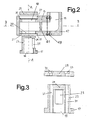
- Fig. 2 On the underside of the housing 13 is a circular, recessed seat 21 and a housing opening 20 surrounded by this for receiving the mounting flange 17, which is attached or integrally formed with one at its rear hollow cylindrical flange core 23 forms a detachable from the housing 13 unit.
- the mounting flange 17 surrounds the inflow opening 15.
- an opening or a window 25 is provided, through which the inflowing compressed air from the tubular flange core 23 enters the housing 13 of the muffler.
- the hollow cylindrical Flanschkern mainly for reasons of soundproofing, closed by a solid bottom wall 24.
- a recessed, circular seat 27 for receiving a flange plate 29 serving as an abutment plate.
- Mounting flange 17, flange core 23 and flange cover 29 have openings 31, 33 (see FIG Fig. 3 ), for receiving clamping screws (not shown), with which the mounting flange 17 and the flange 29 are connected to each other and against the housing 13, ie against the flat bottom surface of the seats 21, 27 can be tightened.
- this expansion bolts are used, which are tightened with a predetermined torque to produce a defined surface pressure.
- sealing rings 35 are arranged in the seats 21 and 20 .
- the number of clamping screws can z. B. four.
- clamping screws When tightening the clamping screws mounting flange 17 and flange 29 are in their seats 21, 27 preferably flush with the housing 13.
- the length of the clamping screws is greater than the height of the muffler housing 13 so that the inserted into the openings 33, 31 clamping screws down protrude beyond the mounting flange 15 and in corresponding threaded holes (not shown) of the connecting flange 9 of the compressor 1 can be screwed.
- the clamping screws thus have a dual function, namely to clamp the mounting flange 17 and the flange 29 against each other and against the seals 35 in the seats 21, 27 and to attach the entire muffler to the flange 7 of the compressor.
- the housing 13 can be rotated relative to the mounting flange 17 about the axis AA of the inlet opening 15 and fixed by tightening the clamping screws in any angular position relative to the compressor 1.
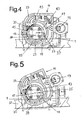
- FIG. 4 and FIG. 5 show top views of the top of the compressor 1 with attached muffler 11, wherein the compressor is mounted on the chassis 37 of a transport vehicle.
- Fig. 5 illustrated in comparison to Fig. 4 How the silencer 11 can be infinitely angularly adjusted relative to the compressor 1 after loosening of the mounting flange 17 against the housing 13 clamping screws and fixed by tightening the clamping screws in a desired angular position relative to the compressor 1.
- the angular adjustment of the muffler takes place about an axis of rotation which is concentric with the central axis of the inlet opening 15 of the muffler or the central axis of the connecting flange 9 of the compressor ( Fig. 1 ).
- the corners of the housing 13 of the muffler 11 are at least partially rounded, as indicated at 39.
- This construction of the muffler 11 with removable and interchangeable mounting flange 17 and flange 29 allows in addition to the continuous angle adjustment about the axis AA in Fig. 2 an additional degree of freedom of adjustment of the muffler 11 relative to the compressor 1, namely by turning by 180 ° about an axis BB perpendicular to the axis AA (see. Fig. 2 ).
- the horizontally cut representation of the muffler 11 in Fig. 4 also illustrates an inventive preferred design of the flow path of the compressed air in the muffler from the inlet port 15 to the outlet port 19.
- the inserted into the housing 13 tubular flange core 23 is over more than half, preferably about three quarters of its circumference of a curved wall 41 and an adjoining part of the housing wall surrounded so that they have a substantially constant distance from the peripheral surface of the Flanschkerns 23, so that a ring channel 43 is formed of substantially constant width.
- As flow obstacles lining with insulating material, metal membranes or the like. (Not shown) is provided.
- the second advantage of the illustrated construction of the muffler is that by suitably dimensioning the width of the annular channel 43, and choosing a suitable material for the walls bounding it, the annular channel 43 can be acoustically tuned to the frequency spectrum to be attenuated, so that an additional sound reduction is achieved.
- the compressed air After the compressed air has passed through the sound-absorbing flow path in the housing 13 of the muffler, it passes to the outlet opening 19, via a housing projection 47, in which a deflection of the compressed air by 90 ° upwards.
- the deflection lug 47 is attached to the main part of the housing 13 of the muffler 11 by fastening screws 49 and can be removed after loosening the screws 49 and in at least one rotated by 180 ° position, possibly also in two rotated by 90 ° positions, again attached, so that the outflow direction of the silenced compressed air is directed downward or to the side.
Landscapes
- Engineering & Computer Science (AREA)
- Mechanical Engineering (AREA)
- General Engineering & Computer Science (AREA)
- Compressor (AREA)
Abstract
Description
Die Erfindung betrifft einen Schalldämpfer gemäß dem Oberbegriff des Anspruchs 1.The invention relates to a silencer according to the preamble of
Vorzugsweise, jedoch nicht ausschließlich, ist der Schalldämpfer zur Verwendung bei Schraubenkompressoren vorgesehen, die an Silofahrzeugen für den Transport von staubförmigen bzw. rieselfähigen Schüttgütern eingebaut werden, um die erforderliche Druckluft zum Auflockern des Schüttgutes im Silo und zum pneumatischen Austragen des Schüttgutes zu liefern. Ein Problem bei dieser und anderen Verwendungen von Schraubenkompressoren ist deren sehr hoher Geräuschpegel. Um diesen zu begrenzen, ist es nötig, mindestens die an der Druckseite des Kompressors ausströmende Druckluft durch einen Schalldämpfer zu leiten. Hierzu sind Schalldämpfer gemäß dem Oberbegriff des Anspruchs 1 bekannt, die an ihrer Einströmöffnung einen Montageflansch aufweisen, der mit einem entsprechenden Flansch am Druckauslass des Kompressors durch Befestigungsmittel, zum Beispiel Schrauben, verbunden werden kann, so dass der Schalldämpfer unmittelbar, ohne Zwischenfügung von Leitungen, an dem Kompressor montiert werden kann.Preferably, but not exclusively, the muffler is intended for use in screw compressors which are installed on silo vehicles for the transport of dusty or free flowing bulk materials to provide the required compressed air for loosening the bulk material in the silo and for the pneumatic discharge of the bulk material. A problem with this and other uses of screw compressors is their very high noise level. To limit this, it is necessary to pass at least the compressed air discharged at the pressure side of the compressor through a silencer. For this purpose, mufflers are known according to the preamble of
Für den Einbau einer derartigen Kompressoreinheit mit einem angeflanschten druckseitigen Schalldämpfer an Lkw-Fahrgestellen steht in der Regel ein sehr begrenzter Raum zur Verfügung, wobei der Einbau häufig durch fahrzeugseitige Hindernisse wie Traversen, Achslenker, Verstärkungsbleche usw. behindert wird. Um den verschiedenen, in der Praxis auftretenden Einbauverhältnissen gerecht zu werden, benötigt man Kompressoreinheiten, deren Schalldämpfer in unterschiedlichen Winkelstellungen am Kompressor befestigt sind. Bei den bisher bekannten Konstruktionen kann der Schalldämpfer in der Regel nur in einer einzigen festgelegen Winkelstellung am Kompressor montiert werden. Allenfalls ist, z. B. bei der Verwendung von vier Befestigungsschrauben für die Flanschverbindung, eine Montage in vier diskreten, um 90° versetzten Winkelstellungen möglich. Um allen in der Praxis auftretenden Einbauverhältnissen gerecht zu werden, müsste eine Vielzahl von Druckluftschalldämpfern bereitgestellt und Lager gehalten werden, die sich jeweils durch die Winkelorientierung des Schalldämpfers relativ zum Kompressor unterscheiden.For the installation of such a compressor unit with a flanged pressure-side muffler to truck chassis is usually a very limited space available, the installation is often hampered by vehicle-side obstacles such as traverses, wishbones, reinforcing plates, etc. In order to meet the various installation conditions occurring in practice, one needs compressor units whose mufflers are fastened in different angular positions on the compressor. In the previously known constructions of the muffler can be mounted in the rule only in a single fixed angular position on the compressor. At most, z. As with the use of four mounting screws for the flange, a mounting in four discrete, offset by 90 ° angular positions possible. To meet all installation conditions occurring in practice, would have a variety of compressed air silencers be provided and held bearings, which differ in each case by the angular orientation of the muffler relative to the compressor.
Der Erfindung liegt die Aufgabe zugrunde, einen Schalldämpfer, der für die Montage an einem Kompressor bestimmt ist, so auszubilden, dass mit einfachen Mitteln die Winkelstellung des Schalldämpfers relativ zur Kompressoreinheit stufenlos geändert werden kann.The invention has for its object to form a muffler, which is intended for mounting on a compressor, so that with simple means the angular position of the muffler can be changed continuously relative to the compressor unit.
Die erfindungsgemäße Lösung der Aufgabe ist im Anspruch 1 angegeben. Die abhängigen Ansprüche 2 bis 9 beziehen sich auf vorteilhafte Weiterausgestaltungen der Erfindung.The achievement of the object according to the invention is specified in
Da erfindungsgemäß der Montageflansch des Schalldämpfers, mit dem der Schalldämpfer am Druckauslass des Kompressors angeflanscht werden kann, nicht starr am Gehäuse des Schalldämpfers ausgebildet, sondern relativ zum Gehäuse stufenlos drehbar und in jeder gewünschten Winkelstellung festlegbar ist, kann bei der Montage des Schalldämpfers am Schraubenkompressor die jeweils günstigste Ausrichtung des Schalldämpfers, in Anpassung an die jeweils vorliegenden Einbauverhältnisse, problemlos mit wenigen Handgriffen vorgenommen werden. Hierdurch wird es in praktisch allen Fällen möglich sein, den Schalldämpfer relativ zum Kompressor so zu positionieren, dass ein Einbau an einem Lkw-Fahrgestell möglich ist, ohne an diesem Umbauten vornehmen zu müssen.Since according to the invention the mounting flange of the muffler, with which the muffler can be flanged to the pressure outlet of the compressor, not rigidly formed on the housing of the muffler, but relative to the housing continuously rotatable and fixable in any desired angular position, can during assembly of the muffler on the screw compressor the each most favorable orientation of the muffler, in adaptation to the respective existing installation conditions, be made easily with a few simple steps. This will make it possible in virtually all cases to position the muffler relative to the compressor so that installation on a truck chassis is possible without having to make these modifications.
Die Ansprüche 2 bis 4 beziehen sich auf eine besonders vorteilhafte Ausgestaltung für die stufenlos drehbare Lagerung des Montageflansches und seine Festlegung am Gehäuse in beliebiger Winkelstellung.The claims 2 to 4 relate to a particularly advantageous embodiment of the continuously rotatable mounting of the mounting flange and its attachment to the housing in any angular position.
Durch die Merkmale der Ansprüche 5 und 6 wird gewährleistet, dass die Strömungsverhältnisse im Gehäuse des Schalldämpfers, und damit auch die Schalldämpfungswirkung, von der Winkelstellung des Montageflansches weitgehend unbeeinflusst bleiben.Due to the features of
Durch das Merkmal des Anspruchs 9 wird zusätzlich zu der Möglichkeit der Winkelverstellung des Schalldämpfers um die Achse der Einströmöffnung eine weitere Möglichkeit geschaffen, die Position des Schalldämpfers relativ zum Kompressor zu verändern, und zwar durch eine Drehung des Schalldämpfers um 180° um eine zur Achse der Einströmöffnung rechtwinklige Achse.The feature of
Eine Ausführungsform der Erfindung wird Anhand der Zeichnungen näher erläutert.An embodiment of the invention will be explained with reference to the drawings.
Es zeigt:
- Fig. 1
- die Seitenansicht eines Schraubenkompressors mit daran befestigtem Schalldämpfer, der im Längsschnitt dargestellt ist;
- Fig. 2
- einen schematischen Längsschnitt des Schalldämpfers, teilweise zerlegt;
- Fig. 3
- die herausnehmbaren Flanschteile des Schalldämpfers im Schnitt gemäß einer gegenüber
Fig. 2 gedrehten axialen Schnittebene; - Fig. 4
- eine Darstellung des Schalldämpfers von oben, teilweise im Schnitt etwa entlang der Linie IV-IV von
Fig. 1 ; - Fig. 5
- eine Schnittdarstellung des Schalldämpfers entsprechend
Fig. 4 , jedoch mit einer gegenüberFig. 4 winkelversetzten Ausrichtung des Schalldämpfers.
- Fig. 1
- the side view of a screw compressor with attached muffler, which is shown in longitudinal section;
- Fig. 2
- a schematic longitudinal section of the muffler, partially disassembled;
- Fig. 3
- the removable flange of the muffler in section according to one opposite
Fig. 2 rotated axial section plane; - Fig. 4
- a view of the muffler from above, partially in section approximately along the line IV-IV of
Fig. 1 ; - Fig. 5
- a sectional view of the muffler accordingly
Fig. 4 but with one oppositeFig. 4 angular misalignment of the muffler.
Auf den Kompressor 1 ist ein allgemein mit 11 bezeichneter Schalldämpfer für die aus dem Kompressor 1 austretende Druckluft aufgesetzt. Der Schalldämpfer 11 hat ein Gehäuse 13, das allgemein kastenförmig mit ebener, zueinander paralleler Ober- und Unterseite ausgebildet ist. An der Unterseite befindet sich eine Einströmöffnung 15, die von einem Montageflansch 17 umgeben ist, der passend zu dem am Kompressor 1 vorgesehenen Anschlussflansch 9 ausgebildet ist und an diesem durch Schrauben in bekannter Weise befestigt werden kann. An der Oberseite des Gehäuses 13 des Schalldämpfers 11, und seitlich versetzt von der Einströmöffnung 15, befindet sich eine Ausströmöffnung 19. Von der Einlassöffnung 15 zur Auslassöffnung 19 strömt die Druckluft entlang einem durch Pfeile in
Auf der Oberseite des Gehäuses 13, und koaxial zu dem Sitz 21, befindet sich ebenfalls ein vertiefter, kreisrunder Sitz 27 für die Aufnahme eines als Widerlagerplatte dienenden Flanschdeckels 29. Montageflansch 17, Flanschkern 23 und Flanschdeckel 29 weisen Öffnungen 31, 33 (siehe
Bei festgezogenen Spannschrauben liegen der Montageflansch 17 und Flanschdeckel 29 in ihren Sitzen 21, 27 jeweils vorzugsweise oberflächenbündig mit dem Gehäuse 13. Die Länge der Spannschrauben ist größer als die Höhe des Schalldämpfergehäuses 13, so dass die in die Öffnungen 33, 31 eingeführten Spannschrauben nach unten über den Montageflansch 15 hinausragen und in entsprechende Gewindebohrungen (nicht dargestellt) des Anschlussflansches 9 des Kompressors 1 eingeschraubt werden können. Die Spannschrauben haben somit eine doppelte Funktion, nämlich den Montageflansch 17 und den Flanschdeckel 29 gegeneinander und gegen die Dichtungen 35 in den Sitzen 21, 27 zu verspannen und den gesamten Schalldämpfer am Anschlussflansch 7 des Kompressors zu befestigen.When tightening the clamping
Wenn der aus dem Montageflansch 17 und dem rohrförmigen Flanschkern 23 bestehende Einsatz von unten und der Flanschdeckel 25 von oben in das Gehäuse 13 eingesetzt ist und die Spannschrauben in die Öffnungen 33, 31 eingeführt und in die Gewindebohrungen des kompressorseitigen Anschlussflansches 7 eingeschraubt, aber noch nicht festgezogen sind, dann kann bei gelockerten Spannschrauben das Gehäuse 13 relativ zum Montageflansch 17 um die Achse A-A der Einlassöffnung 15 stufenlos gedreht und durch Festziehen der Spannschrauben in jeder beliebigen Winkelstellung relativ zum Kompressor 1 festgelegt werden.If the existing from the
In
Vorzugsweise weist das Gehäuse 13 unterhalb des Flanschdeckels 29 eine weitere, zur unteren Gehäuseöffnung 20 koaxiale und durchmessergleiche Öffnung 18 auf (siehe
Die horizontal geschnittene Darstellung des Schalldämpfers 11 in
Durch diese Gestaltung des Schalldämpfers werden zwei Vorteile erreicht. Zum einen ist sichergestellt, dass in jeder Winkelstellung des Montageflansches 17 und Flanschkerns 23 zum Schalldämpfergehäuse 13 (und damit in jeder Winkelstellung des Schalldämpfers 11 gegenüber dem Kompressor 1), innerhalb eines Verstellbereichs von mindestens 180°, das Fenster 25 des Flanschkerns 23 sich im Bereich des Ringkanals 43 befindet. In jeder Winkelstellung des Schalldämpfers 11 ist somit gewährleistet, dass die aus dem Fenster 25 des Flanschkerns 23 auftretende Druckluft zuerst in den Ringkanal 43 gelangt, der sich mit konstanter Breite über den größeren Teil des Umfangs des Flanschkerns 23 erstreckt. Dadurch liegt im gesamten Verstellbereich des Schalldämpfers 11 im Wesentlichen die gleiche Schalldämpfwirkung vor. Der zweite Vorteil der dargestellten Konstruktion des Schalldämpfers besteht darin, dass durch geeignete Bemessung der Breite des Ringkanals 43, und Wahl eines geeigneten Werkstoffs für die ihn begrenzenden Wandungen, der Ringkanal 43 akustisch auf das zu dämpfende Frequenzspektrum abgestimmt werden kann, so dass eine zusätzliche Schallreduktion erzielt wird.This design of the muffler two advantages are achieved. On the one hand it is ensured that in each angular position of the mounting
Nachdem die Druckluft den schalldämpfenden Strömungsweg im Gehäuse 13 des Schalldämpfers durchlaufen hat, gelangt sie zur Auslassöffnung 19, und zwar über einen Gehäuseansatz 47, in welchem eine Umlenkung der Druckluft um 90° nach oben erfolgt. Der Umlenkansatz 47 ist an dem Hauptteil des Gehäuses 13 des Schalldämpfers 11 durch Befestigungsschrauben 49 befestigt und kann nach Lösen der Schrauben 49 abgenommen und in mindestens einer um 180° gedrehten Position, ggf. auch in zwei um 90° gedrehten Positionen, wieder befestigt werden, so dass die Ausströmrichtung der schallgedämpften Druckluft nach unten oder zur Seite gerichtet ist.After the compressed air has passed through the sound-absorbing flow path in the
In
Claims (9)
Applications Claiming Priority (1)
| Application Number | Priority Date | Filing Date | Title |
|---|---|---|---|
| DE202007005097U DE202007005097U1 (en) | 2007-04-05 | 2007-04-05 | Silencer for use on a compressor |
Publications (3)
| Publication Number | Publication Date |
|---|---|
| EP1978259A2 true EP1978259A2 (en) | 2008-10-08 |
| EP1978259A3 EP1978259A3 (en) | 2014-07-30 |
| EP1978259B1 EP1978259B1 (en) | 2017-06-14 |
Family
ID=39629149
Family Applications (1)
| Application Number | Title | Priority Date | Filing Date |
|---|---|---|---|
| EP08006884.4A Not-in-force EP1978259B1 (en) | 2007-04-05 | 2008-04-04 | Silencer for use in a compressor |
Country Status (2)
| Country | Link |
|---|---|
| EP (1) | EP1978259B1 (en) |
| DE (1) | DE202007005097U1 (en) |
Families Citing this family (6)
| Publication number | Priority date | Publication date | Assignee | Title |
|---|---|---|---|---|
| DE202010006419U1 (en) | 2010-05-04 | 2010-09-02 | Emico Gmbh | Broadband damping device for sound damping in industrial facilities, large plants or machines |
| RU2737072C2 (en) | 2015-08-11 | 2020-11-24 | Кэрриер Корпорейшн | Compressor, method of its use and steam compression system |
| CN108138775B (en) * | 2015-10-02 | 2020-11-20 | 开利公司 | Screw compressor resonator array |
| US11808264B2 (en) | 2018-10-02 | 2023-11-07 | Carrier Corporation | Multi-stage resonator for compressor |
| CN113883062A (en) * | 2021-09-18 | 2022-01-04 | 中国船舶重工集团公司第七一一研究所 | Silencing absorber for screw compressor |
| DE102021134652B3 (en) | 2021-12-23 | 2023-05-11 | Man Energy Solutions Se | screw compressor |
Citations (2)
| Publication number | Priority date | Publication date | Assignee | Title |
|---|---|---|---|---|
| DE4107942A1 (en) * | 1990-03-12 | 1991-09-19 | Orpu Gmbh | Sound damper for side channel blower - is for suction and pressure type blower and pivotable through 180 deg. for fixing in required position |
| EP1715238A2 (en) * | 2005-04-21 | 2006-10-25 | Ingersoll-Rand Company | Double throat pulsation dampener for a compressor |
Family Cites Families (2)
| Publication number | Priority date | Publication date | Assignee | Title |
|---|---|---|---|---|
| DE29904410U1 (en) * | 1999-03-10 | 2000-07-20 | GHH-RAND Schraubenkompressoren GmbH & Co. KG, 46145 Oberhausen | Screw compressor |
| DE202004002341U1 (en) * | 2004-02-13 | 2004-05-19 | Schübler Fahrzeugtechnik GmbH | Supply unit arrangement for a motor vehicle |
-
2007
- 2007-04-05 DE DE202007005097U patent/DE202007005097U1/en not_active Expired - Lifetime
-
2008
- 2008-04-04 EP EP08006884.4A patent/EP1978259B1/en not_active Not-in-force
Patent Citations (2)
| Publication number | Priority date | Publication date | Assignee | Title |
|---|---|---|---|---|
| DE4107942A1 (en) * | 1990-03-12 | 1991-09-19 | Orpu Gmbh | Sound damper for side channel blower - is for suction and pressure type blower and pivotable through 180 deg. for fixing in required position |
| EP1715238A2 (en) * | 2005-04-21 | 2006-10-25 | Ingersoll-Rand Company | Double throat pulsation dampener for a compressor |
Also Published As
| Publication number | Publication date |
|---|---|
| DE202007005097U1 (en) | 2008-08-07 |
| EP1978259B1 (en) | 2017-06-14 |
| EP1978259A3 (en) | 2014-07-30 |
Similar Documents
| Publication | Publication Date | Title |
|---|---|---|
| EP1978259B1 (en) | Silencer for use in a compressor | |
| EP0920587B1 (en) | Refrigerant compressor | |
| DE102016214289A1 (en) | Vehicle, with a high-voltage storage | |
| WO2001020180A1 (en) | Bearing device | |
| EP1470320A1 (en) | Fixing device for a turbo-supercharger | |
| EP3121051B1 (en) | Tank system for a vehicle | |
| DE10230044A1 (en) | silencer | |
| EP3538728B1 (en) | Pivot bearing for a side flap of a vehicle | |
| DE10055535A1 (en) | Exhaust silencer for motorcycle or motor vehicle has perforated tube concentrically accommodated inside outer tube buried in sound absorbing material held inside outer casing | |
| DE202006011298U1 (en) | Exhaust air`s sound absorbing device for valve mechanism, has air chamber whose cross section is larger than that of sound absorber, so that air distribution area is defined between lateral surface and chamber wall enclosing absorber | |
| WO2008148443A1 (en) | Blower for a motor vehicle | |
| DE29618052U1 (en) | Steering wheel locking device | |
| WO2006094593A1 (en) | Sanitary water-outlet fitting with jet regulator for deflecting the exiting water jet | |
| EP2273120B1 (en) | Pressure sound damper for a supply apparatus for a motor vehicle | |
| EP1603776B1 (en) | Occupant-protection device | |
| EP2020551B1 (en) | Casing for a ventilation and exhaust element for pipes and fittings | |
| DE102017216226B4 (en) | Drive device for a motor vehicle and corresponding motor vehicle | |
| DE102005008730A1 (en) | Air duct for use in vehicle center console, has fixing hole penetrating lower channel wall, where external wall lies flush and substantially airtight around lower channel wall in border area of fixing hole at body | |
| EP1700668A2 (en) | Device for mounting a motor driven unit to the flywheel housing of the motor | |
| DE10111369A1 (en) | Damper insert for exhaust systems of esp. imported motor vehicles has two chambers connected via expansion chamber with perforated section | |
| WO2018068970A1 (en) | Controller housing for a clutch actuator | |
| EP1447577B1 (en) | Spacer washer | |
| EP3322622A1 (en) | Sound attenuator system | |
| WO2024218332A1 (en) | Jet ventilator | |
| EP1762448B1 (en) | Device for humidifying the window of a motor vehicle and combination of such device with a bodywork part |
Legal Events
| Date | Code | Title | Description |
|---|---|---|---|
| PUAI | Public reference made under article 153(3) epc to a published international application that has entered the european phase |
Free format text: ORIGINAL CODE: 0009012 |
|
| AK | Designated contracting states |
Kind code of ref document: A2 Designated state(s): AT BE BG CH CY CZ DE DK EE ES FI FR GB GR HR HU IE IS IT LI LT LU LV MC MT NL NO PL PT RO SE SI SK TR |
|
| AX | Request for extension of the european patent |
Extension state: AL BA MK RS |
|
| PUAL | Search report despatched |
Free format text: ORIGINAL CODE: 0009013 |
|
| AK | Designated contracting states |
Kind code of ref document: A3 Designated state(s): AT BE BG CH CY CZ DE DK EE ES FI FR GB GR HR HU IE IS IT LI LT LU LV MC MT NL NO PL PT RO SE SI SK TR |
|
| AX | Request for extension of the european patent |
Extension state: AL BA MK RS |
|
| RIC1 | Information provided on ipc code assigned before grant |
Ipc: F04C 29/06 20060101AFI20140625BHEP Ipc: F16L 55/027 20060101ALI20140625BHEP |
|
| 17P | Request for examination filed |
Effective date: 20150130 |
|
| RBV | Designated contracting states (corrected) |
Designated state(s): AT BE BG CH CY CZ DE DK EE ES FI FR GB GR HR HU IE IS IT LI LT LU LV MC MT NL NO PL PT RO SE SI SK TR |
|
| AKX | Designation fees paid |
Designated state(s): AT BE BG CH CY CZ DE DK EE ES FI FR GB GR HR HU IE IS IT LI LT LU LV MC MT NL NO PL PT RO SE SI SK TR |
|
| AXX | Extension fees paid |
Extension state: RS Extension state: AL Extension state: BA Extension state: MK |
|
| 17Q | First examination report despatched |
Effective date: 20160520 |
|
| GRAP | Despatch of communication of intention to grant a patent |
Free format text: ORIGINAL CODE: EPIDOSNIGR1 |
|
| STAA | Information on the status of an ep patent application or granted ep patent |
Free format text: STATUS: GRANT OF PATENT IS INTENDED |
|
| INTG | Intention to grant announced |
Effective date: 20161118 |
|
| GRAS | Grant fee paid |
Free format text: ORIGINAL CODE: EPIDOSNIGR3 |
|
| GRAA | (expected) grant |
Free format text: ORIGINAL CODE: 0009210 |
|
| STAA | Information on the status of an ep patent application or granted ep patent |
Free format text: STATUS: THE PATENT HAS BEEN GRANTED |
|
| AK | Designated contracting states |
Kind code of ref document: B1 Designated state(s): AT BE BG CH CY CZ DE DK EE ES FI FR GB GR HR HU IE IS IT LI LT LU LV MC MT NL NO PL PT RO SE SI SK TR |
|
| RAP1 | Party data changed (applicant data changed or rights of an application transferred) |
Owner name: INGERSOLL-RAND INTERNATIONAL LIMITED (IRLAND) |
|
| REG | Reference to a national code |
Ref country code: GB Ref legal event code: FG4D Free format text: NOT ENGLISH |
|
| REG | Reference to a national code |
Ref country code: CH Ref legal event code: EP Ref country code: AT Ref legal event code: REF Ref document number: 901263 Country of ref document: AT Kind code of ref document: T Effective date: 20170615 |
|
| REG | Reference to a national code |
Ref country code: IE Ref legal event code: FG4D Free format text: LANGUAGE OF EP DOCUMENT: GERMAN |
|
| REG | Reference to a national code |
Ref country code: DE Ref legal event code: R096 Ref document number: 502008015377 Country of ref document: DE |
|
| REG | Reference to a national code |
Ref country code: NL Ref legal event code: MP Effective date: 20170614 |
|
| REG | Reference to a national code |
Ref country code: LT Ref legal event code: MG4D |
|
| PG25 | Lapsed in a contracting state [announced via postgrant information from national office to epo] |
Ref country code: ES Free format text: LAPSE BECAUSE OF FAILURE TO SUBMIT A TRANSLATION OF THE DESCRIPTION OR TO PAY THE FEE WITHIN THE PRESCRIBED TIME-LIMIT Effective date: 20170614 Ref country code: NO Free format text: LAPSE BECAUSE OF FAILURE TO SUBMIT A TRANSLATION OF THE DESCRIPTION OR TO PAY THE FEE WITHIN THE PRESCRIBED TIME-LIMIT Effective date: 20170914 Ref country code: LT Free format text: LAPSE BECAUSE OF FAILURE TO SUBMIT A TRANSLATION OF THE DESCRIPTION OR TO PAY THE FEE WITHIN THE PRESCRIBED TIME-LIMIT Effective date: 20170614 Ref country code: FI Free format text: LAPSE BECAUSE OF FAILURE TO SUBMIT A TRANSLATION OF THE DESCRIPTION OR TO PAY THE FEE WITHIN THE PRESCRIBED TIME-LIMIT Effective date: 20170614 Ref country code: HR Free format text: LAPSE BECAUSE OF FAILURE TO SUBMIT A TRANSLATION OF THE DESCRIPTION OR TO PAY THE FEE WITHIN THE PRESCRIBED TIME-LIMIT Effective date: 20170614 Ref country code: GR Free format text: LAPSE BECAUSE OF FAILURE TO SUBMIT A TRANSLATION OF THE DESCRIPTION OR TO PAY THE FEE WITHIN THE PRESCRIBED TIME-LIMIT Effective date: 20170915 |
|
| PG25 | Lapsed in a contracting state [announced via postgrant information from national office to epo] |
Ref country code: BG Free format text: LAPSE BECAUSE OF FAILURE TO SUBMIT A TRANSLATION OF THE DESCRIPTION OR TO PAY THE FEE WITHIN THE PRESCRIBED TIME-LIMIT Effective date: 20170914 Ref country code: LV Free format text: LAPSE BECAUSE OF FAILURE TO SUBMIT A TRANSLATION OF THE DESCRIPTION OR TO PAY THE FEE WITHIN THE PRESCRIBED TIME-LIMIT Effective date: 20170614 Ref country code: NL Free format text: LAPSE BECAUSE OF FAILURE TO SUBMIT A TRANSLATION OF THE DESCRIPTION OR TO PAY THE FEE WITHIN THE PRESCRIBED TIME-LIMIT Effective date: 20170614 Ref country code: SE Free format text: LAPSE BECAUSE OF FAILURE TO SUBMIT A TRANSLATION OF THE DESCRIPTION OR TO PAY THE FEE WITHIN THE PRESCRIBED TIME-LIMIT Effective date: 20170614 |
|
| PG25 | Lapsed in a contracting state [announced via postgrant information from national office to epo] |
Ref country code: EE Free format text: LAPSE BECAUSE OF FAILURE TO SUBMIT A TRANSLATION OF THE DESCRIPTION OR TO PAY THE FEE WITHIN THE PRESCRIBED TIME-LIMIT Effective date: 20170614 Ref country code: CZ Free format text: LAPSE BECAUSE OF FAILURE TO SUBMIT A TRANSLATION OF THE DESCRIPTION OR TO PAY THE FEE WITHIN THE PRESCRIBED TIME-LIMIT Effective date: 20170614 Ref country code: SK Free format text: LAPSE BECAUSE OF FAILURE TO SUBMIT A TRANSLATION OF THE DESCRIPTION OR TO PAY THE FEE WITHIN THE PRESCRIBED TIME-LIMIT Effective date: 20170614 Ref country code: RO Free format text: LAPSE BECAUSE OF FAILURE TO SUBMIT A TRANSLATION OF THE DESCRIPTION OR TO PAY THE FEE WITHIN THE PRESCRIBED TIME-LIMIT Effective date: 20170614 |
|
| PG25 | Lapsed in a contracting state [announced via postgrant information from national office to epo] |
Ref country code: IS Free format text: LAPSE BECAUSE OF FAILURE TO SUBMIT A TRANSLATION OF THE DESCRIPTION OR TO PAY THE FEE WITHIN THE PRESCRIBED TIME-LIMIT Effective date: 20171014 Ref country code: IT Free format text: LAPSE BECAUSE OF FAILURE TO SUBMIT A TRANSLATION OF THE DESCRIPTION OR TO PAY THE FEE WITHIN THE PRESCRIBED TIME-LIMIT Effective date: 20170614 Ref country code: PL Free format text: LAPSE BECAUSE OF FAILURE TO SUBMIT A TRANSLATION OF THE DESCRIPTION OR TO PAY THE FEE WITHIN THE PRESCRIBED TIME-LIMIT Effective date: 20170614 |
|
| REG | Reference to a national code |
Ref country code: DE Ref legal event code: R097 Ref document number: 502008015377 Country of ref document: DE |
|
| PLBE | No opposition filed within time limit |
Free format text: ORIGINAL CODE: 0009261 |
|
| STAA | Information on the status of an ep patent application or granted ep patent |
Free format text: STATUS: NO OPPOSITION FILED WITHIN TIME LIMIT |
|
| PG25 | Lapsed in a contracting state [announced via postgrant information from national office to epo] |
Ref country code: DK Free format text: LAPSE BECAUSE OF FAILURE TO SUBMIT A TRANSLATION OF THE DESCRIPTION OR TO PAY THE FEE WITHIN THE PRESCRIBED TIME-LIMIT Effective date: 20170614 |
|
| 26N | No opposition filed |
Effective date: 20180315 |
|
| PG25 | Lapsed in a contracting state [announced via postgrant information from national office to epo] |
Ref country code: SI Free format text: LAPSE BECAUSE OF FAILURE TO SUBMIT A TRANSLATION OF THE DESCRIPTION OR TO PAY THE FEE WITHIN THE PRESCRIBED TIME-LIMIT Effective date: 20170614 |
|
| PG25 | Lapsed in a contracting state [announced via postgrant information from national office to epo] |
Ref country code: MT Free format text: LAPSE BECAUSE OF FAILURE TO SUBMIT A TRANSLATION OF THE DESCRIPTION OR TO PAY THE FEE WITHIN THE PRESCRIBED TIME-LIMIT Effective date: 20170614 |
|
| REG | Reference to a national code |
Ref country code: DE Ref legal event code: R119 Ref document number: 502008015377 Country of ref document: DE |
|
| PG25 | Lapsed in a contracting state [announced via postgrant information from national office to epo] |
Ref country code: MC Free format text: LAPSE BECAUSE OF FAILURE TO SUBMIT A TRANSLATION OF THE DESCRIPTION OR TO PAY THE FEE WITHIN THE PRESCRIBED TIME-LIMIT Effective date: 20170614 |
|
| REG | Reference to a national code |
Ref country code: CH Ref legal event code: PL |
|
| REG | Reference to a national code |
Ref country code: BE Ref legal event code: MM Effective date: 20180430 |
|
| GBPC | Gb: european patent ceased through non-payment of renewal fee |
Effective date: 20180404 |
|
| REG | Reference to a national code |
Ref country code: IE Ref legal event code: MM4A |
|
| PG25 | Lapsed in a contracting state [announced via postgrant information from national office to epo] |
Ref country code: LU Free format text: LAPSE BECAUSE OF NON-PAYMENT OF DUE FEES Effective date: 20180404 Ref country code: DE Free format text: LAPSE BECAUSE OF NON-PAYMENT OF DUE FEES Effective date: 20181101 |
|
| PG25 | Lapsed in a contracting state [announced via postgrant information from national office to epo] |
Ref country code: LI Free format text: LAPSE BECAUSE OF NON-PAYMENT OF DUE FEES Effective date: 20180430 Ref country code: CH Free format text: LAPSE BECAUSE OF NON-PAYMENT OF DUE FEES Effective date: 20180430 Ref country code: GB Free format text: LAPSE BECAUSE OF NON-PAYMENT OF DUE FEES Effective date: 20180404 Ref country code: BE Free format text: LAPSE BECAUSE OF NON-PAYMENT OF DUE FEES Effective date: 20180430 |
|
| PG25 | Lapsed in a contracting state [announced via postgrant information from national office to epo] |
Ref country code: IE Free format text: LAPSE BECAUSE OF NON-PAYMENT OF DUE FEES Effective date: 20180404 Ref country code: FR Free format text: LAPSE BECAUSE OF NON-PAYMENT OF DUE FEES Effective date: 20180430 |
|
| REG | Reference to a national code |
Ref country code: AT Ref legal event code: MM01 Ref document number: 901263 Country of ref document: AT Kind code of ref document: T Effective date: 20180404 |
|
| PG25 | Lapsed in a contracting state [announced via postgrant information from national office to epo] |
Ref country code: AT Free format text: LAPSE BECAUSE OF NON-PAYMENT OF DUE FEES Effective date: 20180404 |
|
| PG25 | Lapsed in a contracting state [announced via postgrant information from national office to epo] |
Ref country code: TR Free format text: LAPSE BECAUSE OF FAILURE TO SUBMIT A TRANSLATION OF THE DESCRIPTION OR TO PAY THE FEE WITHIN THE PRESCRIBED TIME-LIMIT Effective date: 20170614 |
|
| PG25 | Lapsed in a contracting state [announced via postgrant information from national office to epo] |
Ref country code: HU Free format text: LAPSE BECAUSE OF FAILURE TO SUBMIT A TRANSLATION OF THE DESCRIPTION OR TO PAY THE FEE WITHIN THE PRESCRIBED TIME-LIMIT; INVALID AB INITIO Effective date: 20080404 Ref country code: PT Free format text: LAPSE BECAUSE OF FAILURE TO SUBMIT A TRANSLATION OF THE DESCRIPTION OR TO PAY THE FEE WITHIN THE PRESCRIBED TIME-LIMIT Effective date: 20170614 |
|
| PG25 | Lapsed in a contracting state [announced via postgrant information from national office to epo] |
Ref country code: CY Free format text: LAPSE BECAUSE OF FAILURE TO SUBMIT A TRANSLATION OF THE DESCRIPTION OR TO PAY THE FEE WITHIN THE PRESCRIBED TIME-LIMIT Effective date: 20170614 |