EP1978191A2 - Verriegelungsvorrichtung für eine Kühlraumschiebetür - Google Patents
Verriegelungsvorrichtung für eine Kühlraumschiebetür Download PDFInfo
- Publication number
- EP1978191A2 EP1978191A2 EP08101955A EP08101955A EP1978191A2 EP 1978191 A2 EP1978191 A2 EP 1978191A2 EP 08101955 A EP08101955 A EP 08101955A EP 08101955 A EP08101955 A EP 08101955A EP 1978191 A2 EP1978191 A2 EP 1978191A2
- Authority
- EP
- European Patent Office
- Prior art keywords
- seat
- locking member
- component
- door
- lever
- Prior art date
- Legal status (The legal status is an assumption and is not a legal conclusion. Google has not performed a legal analysis and makes no representation as to the accuracy of the status listed.)
- Granted
Links
Images


Classifications
-
- E—FIXED CONSTRUCTIONS
- E05—LOCKS; KEYS; WINDOW OR DOOR FITTINGS; SAFES
- E05B—LOCKS; ACCESSORIES THEREFOR; HANDCUFFS
- E05B65/00—Locks or fastenings for special use
- E05B65/0042—For refrigerators or cold rooms
- E05B65/0053—For refrigerators or cold rooms with safety release from inside
-
- E—FIXED CONSTRUCTIONS
- E05—LOCKS; KEYS; WINDOW OR DOOR FITTINGS; SAFES
- E05B—LOCKS; ACCESSORIES THEREFOR; HANDCUFFS
- E05B15/00—Other details of locks; Parts for engagement by bolts of fastening devices
- E05B15/0093—Weight arrangements in locks; gravity activated lock parts
-
- E—FIXED CONSTRUCTIONS
- E05—LOCKS; KEYS; WINDOW OR DOOR FITTINGS; SAFES
- E05B—LOCKS; ACCESSORIES THEREFOR; HANDCUFFS
- E05B15/00—Other details of locks; Parts for engagement by bolts of fastening devices
- E05B15/02—Striking-plates; Keepers; Bolt staples; Escutcheons
- E05B15/0205—Striking-plates, keepers, staples
-
- E—FIXED CONSTRUCTIONS
- E05—LOCKS; KEYS; WINDOW OR DOOR FITTINGS; SAFES
- E05B—LOCKS; ACCESSORIES THEREFOR; HANDCUFFS
- E05B63/00—Locks or fastenings with special structural characteristics
- E05B63/0052—Locks mounted on the "frame" cooperating with means on the "wing"
-
- E—FIXED CONSTRUCTIONS
- E05—LOCKS; KEYS; WINDOW OR DOOR FITTINGS; SAFES
- E05B—LOCKS; ACCESSORIES THEREFOR; HANDCUFFS
- E05B63/00—Locks or fastenings with special structural characteristics
- E05B63/18—Locks or fastenings with special structural characteristics with arrangements independent of the locking mechanism for retaining the bolt or latch in the retracted position
- E05B63/20—Locks or fastenings with special structural characteristics with arrangements independent of the locking mechanism for retaining the bolt or latch in the retracted position released automatically when the wing is closed
-
- E—FIXED CONSTRUCTIONS
- E05—LOCKS; KEYS; WINDOW OR DOOR FITTINGS; SAFES
- E05B—LOCKS; ACCESSORIES THEREFOR; HANDCUFFS
- E05B65/00—Locks or fastenings for special use
- E05B65/08—Locks or fastenings for special use for sliding wings
- E05B65/0864—Locks or fastenings for special use for sliding wings the bolts sliding perpendicular to the wings
Definitions
- the present invention relates to a fastener device in accordance with the introduction to the main claim.
- a known device associated with a wall close to an opening in said coldroom relative to which the door moves (along a path parallel to a floor or lower surface), comprises a seat into which an element projecting from the door, such as a hook-like element or chain, penetrates. On penetrating into the corresponding seat, this projecting element is locked therein in order to fasten the door to the wall in its closed position.
- Another known solution uses a device formed with two parts movable relative to each other in the manner of a sliding drawer to retain between them a projecting element, specifically a chain, of the sliding door.
- the two parts can be moved relative to each other if released by a key, whereas they are automatically locked when one is positioned on the other after receiving the projecting door element within them. Only when in this position can said key be removed from the known device.
- This solution is complicated in use because an operator has to use both hands to achieve coupling between the device and the projecting door element, this being extremely uncomfortable.
- the key is always associated with the known device when the door is open, hence lacking security.
- An object of the present invention is to provide a fastener device which represents an improvement over known devices.
- a particular object of the invention is to provide a fastener device for a coldroom sliding door which enables this latter to be fastened in its closed position totally automatically without the need for an operator to intervene on the device.
- Another object is to provide a device of the stated type which does not require any vertical movement of the door relative to the surface along which it slides, and which therefore does not require particular means to ensure door sealing once it has been retained by said device.
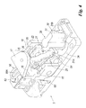
- a device of the invention is indicated overall by 1. It comprises a body 2 presenting two components 3 and 4, the first component 3 presenting a locking mechanism for a sliding door (not shown), said mechanism being protected by the second component 4 (being inserted into a cavity 5) when this latter is coupled to the first component.
- the body 2 comprises a hook-shaped portion 7 presenting a first part 8 disposed parallel to and spaced from a portion 9 of the first component 3, to hence define an aperture 10 through which the projecting element, in this case a ring 11 of a chain (not shown) associated with the sliding door, is inserted to lock the movement of said door after it has closed an opening provided in a wall (not shown).
- the device 1 is positioned on this wall, in proximity to the opening.
- the hook-shaped element is defined by an L-shaped portion 15 presenting a first part 16 perpendicular to a base 3A of the component 3, and a second part 17 parallel to this base, this latter being disposed above the portion 9 of the first component 3 of the body 2.
- the lever element 22 presents a free end 26, preferably carrying a locking member 25 for the projecting door element 11.
- This member is defined in the illustrated example by a spherical body associated freely with (or glued to) said end 26, and emerges from an aperture or seat 29 provided in the portion 9 of the component 3 of the body 2.
- This portion 9 is an element coupled to the shoulders 18 and 20 of said component 3.
- the spherical body or locking member 25 of the lever element 22 can assume two working positions relative to the corresponding seat 29: in a first position (shown in Figures 1 , 2 and 6 ) it projects therefrom to enter the aperture 10 of the body 2, while in the second position it retracts into said seat to free the aperture 10.
- the retraction movement into the seat occurs totally automatically when the projecting door element 11 is inserted into the aperture 10, by its pressure on said spherical body 25. This pressure is transferred to the lever element 22, which rotates with the shaft 21 against the spring 23 (or equivalent elastic element) to hence enable the sphere to retract into the corresponding seat.
- the spring 23 returns the spherical body 25 to the outside of its seat 29, to lock the projecting element or chain ring 11 within the aperture 10 of the device 1 (to hence fasten the door to the device 1 in its closed position).
- a rotary element 30 is provided presenting an arch-shaped portion 31 rising gradually from a base 32 such that an end 31A of this portion 31 is sunken relative to a second end 31 B thereof.
- the element 30 is mounted about a pin 35 of the first component 3 of the body 2 and can rotate about it by the action of a usual door lock 38 (positioned on the base 32) having a known pawl 39 which cooperates with a tang 40 projecting laterally from the portion 31 of the element 30 and is integral therewith.
- the device 1 is mounted on the wall vertically, such as to present the aperture 10 facing the surface along which the door slides.
- the key with one hand by the user
- the element 11 is allowed to escape by gravity from said aperture 10 when the spherical body 25 retracts into the corresponding seat.
- a cylindrical element 49 extends on one side 50 of the first component 3 of the body 2 of the device 1 (the side on which said first component 3 is fixed to a wall), and is associated with a rod 51 connected to a pushbutton (not shown) positioned inside the coldroom.
- This solution enables the door (when closed) to be opened from inside the coldroom, to enable a person present therein to leave.
- the rod cooperates with a portion 54 of the lever element 22; this cooperation results in lifting of the end 43 of the element 22 from the base 3A of the first component 3 of the device body 2, i.e. a rotation of the element 22 about the shaft 21, this rotation causing the spherical body 25 to retract into its seat and the subsequent release of the element 11 from the fastener device, making it possible to open the door from inside the coldroom.
- the spring 23 cooperates with a lever 56 comprising a first arm 57 (acting on the spring 23) and a second arm 58, said lever being pivoted about a pin 60 associated with the component 3 of the device body 2.
- the arm 58 presents an end portion 58A cooperating with a switch 62 (associated with an electrical connection positioned within the component 3 of the body 2) operating an electric motor for automatically moving the door into its open position.
- the spherical body 25 is freely supported by the end 26 of the lever element 22 and cooperates, urged by said element 22, with a stop element 65 rigid with the second part 17 of the L-shaped portion 15 rigid with the first component 3 of the device body 2.
- the use of the device of the invention is apparent from the aforegoing description.
- the device is easy to use by the user in that in order to fasten the door in the closed position, the user does not have to act on the device 1, while to open the door the user has merely to rotate the key in the lock, leading to the simple release, advantageously by gravity, of the element 11 from the device 1.
- the key serves only to open the door and can be removed after opening.
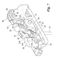
- FIGS 7 to 10 show a variant of the invention.
- the lever element 22 can be seen provided with a (lateral) portion 100 facing the second arm 58 of the lever 56.
- the portion 100 comprises a recess 101 bounded by raised edges 102 and 103 with which a projecting tooth 104 associated with said second arm 58 cooperates.
- This tooth has an undercut and is arranged to rotate the lever element 22 about the shaft 21 when the ring element 11 is inserted into the aperture 10.
- the ring presses on a pin or pawl 110 associated with the part 16 of the portion 15 and movable within a seat 111 thereof.
- the pin 110 penetrates into the seat until it contacts the lever 56 and makes it rotate about the pin 60.
- This rotation causes said tooth 104 to act on the end 102 of the recess 101, to rotate (by thrusting) the lever element 22 about the shaft 21.
- the spherical body or locking member 25 becomes positioned against the stop element 65 to lock the element 11 within the aperture 10.
- Said element 11 is released by a key as in the case of the embodiment of Figures 1-6 or by the action of the rod 51 on the element 22. It should be noted that once the spherical body has been brought into its seat 29, it remains therein as the spring 23 tends to maintain the lever element 22 rotated such as to urge the spherical body 25 to the outside of said seat 29.
- the spring 23 presents a second end 23K superposed on the end 43 of the lever element 22.
Landscapes
- Physics & Mathematics (AREA)
- Thermal Sciences (AREA)
- Lock And Its Accessories (AREA)
- Refrigerator Housings (AREA)
- Devices That Are Associated With Refrigeration Equipment (AREA)
Applications Claiming Priority (1)
| Application Number | Priority Date | Filing Date | Title |
|---|---|---|---|
| ITMI20070678 ITMI20070678A1 (it) | 2007-04-03 | 2007-04-03 | Dispositivo di chiusura di una porta scorrevole di una cella frigorifera |
Publications (3)
| Publication Number | Publication Date |
|---|---|
| EP1978191A2 true EP1978191A2 (de) | 2008-10-08 |
| EP1978191A3 EP1978191A3 (de) | 2012-12-12 |
| EP1978191B1 EP1978191B1 (de) | 2014-05-14 |
Family
ID=39642648
Family Applications (1)
| Application Number | Title | Priority Date | Filing Date |
|---|---|---|---|
| EP20080101955 Not-in-force EP1978191B1 (de) | 2007-04-03 | 2008-02-25 | Verriegelungsvorrichtung für eine Kühlraumschiebetür |
Country Status (2)
| Country | Link |
|---|---|
| EP (1) | EP1978191B1 (de) |
| IT (1) | ITMI20070678A1 (de) |
Cited By (1)
| Publication number | Priority date | Publication date | Assignee | Title |
|---|---|---|---|---|
| CN106677631A (zh) * | 2016-10-14 | 2017-05-17 | 东莞市怡丰锁业有限公司 | 一种行李箱锁扣 |
Family Cites Families (7)
| Publication number | Priority date | Publication date | Assignee | Title |
|---|---|---|---|---|
| US3071958A (en) * | 1961-08-30 | 1963-01-08 | Truson Corp | Protective device for doors |
| US3657908A (en) * | 1970-06-02 | 1972-04-25 | Taylor Lock Co | Chain door lock |
| US3870354A (en) * | 1973-06-18 | 1975-03-11 | Herman Prahl | Drop bolt snap latch locking mechanism |
| AU543761B2 (en) * | 1980-04-02 | 1985-05-02 | Lockwood Security Products Pty Limited | Window fastening |
| GB2277553B (en) * | 1993-04-29 | 1996-07-31 | Charles Augustine Beare | Lock |
| DE19906622A1 (de) * | 1999-02-17 | 2000-08-24 | Bremicker Soehne Kg A | Fensterschloß |
| ITMI20050078U1 (it) * | 2005-03-09 | 2006-09-10 | Ik Interklimat S P A | Chiusura per porte di celle frigorifere atta a permettere la facile regolazione della posizione della porta rispetto ad una struttura della cella |
-
2007
- 2007-04-03 IT ITMI20070678 patent/ITMI20070678A1/it unknown
-
2008
- 2008-02-25 EP EP20080101955 patent/EP1978191B1/de not_active Not-in-force
Cited By (2)
| Publication number | Priority date | Publication date | Assignee | Title |
|---|---|---|---|---|
| CN106677631A (zh) * | 2016-10-14 | 2017-05-17 | 东莞市怡丰锁业有限公司 | 一种行李箱锁扣 |
| CN106677631B (zh) * | 2016-10-14 | 2022-03-22 | 东莞市怡丰锁业有限公司 | 一种行李箱锁扣 |
Also Published As
| Publication number | Publication date |
|---|---|
| EP1978191A3 (de) | 2012-12-12 |
| EP1978191B1 (de) | 2014-05-14 |
| ITMI20070678A1 (it) | 2008-10-04 |
Similar Documents
| Publication | Publication Date | Title |
|---|---|---|
| CN104470403B (zh) | 抽屉滑轨及电致动式锁定机构 | |
| CN216406444U (zh) | 具有锁定与否显示功能的窗户用锁定装置 | |
| EP2468577A3 (de) | Vorrichtung zum Öffnen und Schließen eines Deckels | |
| US2183121A (en) | Latch mechanism | |
| BR112017009357B1 (pt) | Trinco de excêntrico, sistema de trinco e processo para liberar um sistema de trinco | |
| JPH04261982A (ja) | トランク扉等の電動式ロック装置 | |
| KR20110106231A (ko) | 가구유닛의 가동부 개폐장치 | |
| KR101635255B1 (ko) | 도어를 개방하기 위한, 특히 가정용품의 도어를 위한 시스템 | |
| CN209071929U (zh) | 机械联锁机构 | |
| JP3339842B2 (ja) | 扉開閉用ハンドル装置 | |
| US8240177B2 (en) | Keyed lock door handle | |
| ES2297806T3 (es) | Dispositivo de accionamiento para un aparato electrico interruptor con dispositivo de cierre. | |
| EP1978191A2 (de) | Verriegelungsvorrichtung für eine Kühlraumschiebetür | |
| JP6204774B2 (ja) | 南京錠 | |
| US4061383A (en) | Automatically locking crossbolt deadlock | |
| CN112641480B (zh) | 用于外科手术的直线型缝切器 | |
| CN221220084U (zh) | 一种滑门锁 | |
| KR101958184B1 (ko) | 사물함용 잠금장치 | |
| CN105442956B (zh) | 一种安全门锁 | |
| CN205069435U (zh) | 一种主开关分合闸手柄 | |
| CN210888464U (zh) | 一种改进的手动天地插销机构 | |
| CN202100083U (zh) | 一种平开门机活插形锁定机构 | |
| CN220381956U (zh) | 一种对称式推拉装置 | |
| US20070255425A1 (en) | Connection Part for Prostheses | |
| CN223469136U (zh) | 逃生锁 |
Legal Events
| Date | Code | Title | Description |
|---|---|---|---|
| PUAI | Public reference made under article 153(3) epc to a published international application that has entered the european phase |
Free format text: ORIGINAL CODE: 0009012 |
|
| AK | Designated contracting states |
Kind code of ref document: A2 Designated state(s): AT BE BG CH CY CZ DE DK EE ES FI FR GB GR HR HU IE IS IT LI LT LU LV MC MT NL NO PL PT RO SE SI SK TR |
|
| AX | Request for extension of the european patent |
Extension state: AL BA MK RS |
|
| PUAL | Search report despatched |
Free format text: ORIGINAL CODE: 0009013 |
|
| AK | Designated contracting states |
Kind code of ref document: A3 Designated state(s): AT BE BG CH CY CZ DE DK EE ES FI FR GB GR HR HU IE IS IT LI LT LU LV MC MT NL NO PL PT RO SE SI SK TR |
|
| AX | Request for extension of the european patent |
Extension state: AL BA MK RS |
|
| RIC1 | Information provided on ipc code assigned before grant |
Ipc: E05B 15/02 20060101ALN20121105BHEP Ipc: E05B 65/00 20060101AFI20121105BHEP |
|
| 17P | Request for examination filed |
Effective date: 20130606 |
|
| RBV | Designated contracting states (corrected) |
Designated state(s): AT BE BG CH CY CZ DE DK EE ES FI FR GB GR HR HU IE IS IT LI LT LU LV MC MT NL NO PL PT RO SE SI SK TR |
|
| RIC1 | Information provided on ipc code assigned before grant |
Ipc: E05B 15/02 20060101ALN20130625BHEP Ipc: E05B 65/00 20060101AFI20130625BHEP |
|
| AKX | Designation fees paid |
Designated state(s): AT BE BG CH CY CZ DE DK EE ES FI FR GB GR HR HU IE IS IT LI LT LU LV MC MT NL NO PL PT RO SE SI SK TR |
|
| GRAP | Despatch of communication of intention to grant a patent |
Free format text: ORIGINAL CODE: EPIDOSNIGR1 |
|
| INTG | Intention to grant announced |
Effective date: 20131015 |
|
| GRAS | Grant fee paid |
Free format text: ORIGINAL CODE: EPIDOSNIGR3 |
|
| GRAP | Despatch of communication of intention to grant a patent |
Free format text: ORIGINAL CODE: EPIDOSNIGR1 |
|
| RIC1 | Information provided on ipc code assigned before grant |
Ipc: E05B 15/02 20060101ALN20140303BHEP Ipc: E05B 65/00 20060101AFI20140303BHEP |
|
| GRAA | (expected) grant |
Free format text: ORIGINAL CODE: 0009210 |
|
| INTG | Intention to grant announced |
Effective date: 20140319 |
|
| AK | Designated contracting states |
Kind code of ref document: B1 Designated state(s): AT BE BG CH CY CZ DE DK EE ES FI FR GB GR HR HU IE IS IT LI LT LU LV MC MT NL NO PL PT RO SE SI SK TR |
|
| REG | Reference to a national code |
Ref country code: GB Ref legal event code: FG4D |
|
| REG | Reference to a national code |
Ref country code: AT Ref legal event code: REF Ref document number: 668438 Country of ref document: AT Kind code of ref document: T Effective date: 20140615 |
|
| REG | Reference to a national code |
Ref country code: IE Ref legal event code: FG4D |
|
| REG | Reference to a national code |
Ref country code: DE Ref legal event code: R096 Ref document number: 602008032224 Country of ref document: DE Effective date: 20140626 |
|
| REG | Reference to a national code |
Ref country code: AT Ref legal event code: MK05 Ref document number: 668438 Country of ref document: AT Kind code of ref document: T Effective date: 20140514 Ref country code: NL Ref legal event code: VDEP Effective date: 20140514 |
|
| REG | Reference to a national code |
Ref country code: LT Ref legal event code: MG4D |
|
| PG25 | Lapsed in a contracting state [announced via postgrant information from national office to epo] |
Ref country code: FI Free format text: LAPSE BECAUSE OF FAILURE TO SUBMIT A TRANSLATION OF THE DESCRIPTION OR TO PAY THE FEE WITHIN THE PRESCRIBED TIME-LIMIT Effective date: 20140514 Ref country code: CY Free format text: LAPSE BECAUSE OF FAILURE TO SUBMIT A TRANSLATION OF THE DESCRIPTION OR TO PAY THE FEE WITHIN THE PRESCRIBED TIME-LIMIT Effective date: 20140514 Ref country code: IS Free format text: LAPSE BECAUSE OF FAILURE TO SUBMIT A TRANSLATION OF THE DESCRIPTION OR TO PAY THE FEE WITHIN THE PRESCRIBED TIME-LIMIT Effective date: 20140914 Ref country code: GR Free format text: LAPSE BECAUSE OF FAILURE TO SUBMIT A TRANSLATION OF THE DESCRIPTION OR TO PAY THE FEE WITHIN THE PRESCRIBED TIME-LIMIT Effective date: 20140815 Ref country code: NO Free format text: LAPSE BECAUSE OF FAILURE TO SUBMIT A TRANSLATION OF THE DESCRIPTION OR TO PAY THE FEE WITHIN THE PRESCRIBED TIME-LIMIT Effective date: 20140814 Ref country code: LT Free format text: LAPSE BECAUSE OF FAILURE TO SUBMIT A TRANSLATION OF THE DESCRIPTION OR TO PAY THE FEE WITHIN THE PRESCRIBED TIME-LIMIT Effective date: 20140514 |
|
| PG25 | Lapsed in a contracting state [announced via postgrant information from national office to epo] |
Ref country code: LV Free format text: LAPSE BECAUSE OF FAILURE TO SUBMIT A TRANSLATION OF THE DESCRIPTION OR TO PAY THE FEE WITHIN THE PRESCRIBED TIME-LIMIT Effective date: 20140514 Ref country code: AT Free format text: LAPSE BECAUSE OF FAILURE TO SUBMIT A TRANSLATION OF THE DESCRIPTION OR TO PAY THE FEE WITHIN THE PRESCRIBED TIME-LIMIT Effective date: 20140514 Ref country code: PL Free format text: LAPSE BECAUSE OF FAILURE TO SUBMIT A TRANSLATION OF THE DESCRIPTION OR TO PAY THE FEE WITHIN THE PRESCRIBED TIME-LIMIT Effective date: 20140514 Ref country code: HR Free format text: LAPSE BECAUSE OF FAILURE TO SUBMIT A TRANSLATION OF THE DESCRIPTION OR TO PAY THE FEE WITHIN THE PRESCRIBED TIME-LIMIT Effective date: 20140514 Ref country code: ES Free format text: LAPSE BECAUSE OF FAILURE TO SUBMIT A TRANSLATION OF THE DESCRIPTION OR TO PAY THE FEE WITHIN THE PRESCRIBED TIME-LIMIT Effective date: 20140514 Ref country code: SE Free format text: LAPSE BECAUSE OF FAILURE TO SUBMIT A TRANSLATION OF THE DESCRIPTION OR TO PAY THE FEE WITHIN THE PRESCRIBED TIME-LIMIT Effective date: 20140514 |
|
| PG25 | Lapsed in a contracting state [announced via postgrant information from national office to epo] |
Ref country code: PT Free format text: LAPSE BECAUSE OF FAILURE TO SUBMIT A TRANSLATION OF THE DESCRIPTION OR TO PAY THE FEE WITHIN THE PRESCRIBED TIME-LIMIT Effective date: 20140915 |
|
| PG25 | Lapsed in a contracting state [announced via postgrant information from national office to epo] |
Ref country code: RO Free format text: LAPSE BECAUSE OF FAILURE TO SUBMIT A TRANSLATION OF THE DESCRIPTION OR TO PAY THE FEE WITHIN THE PRESCRIBED TIME-LIMIT Effective date: 20140514 Ref country code: DK Free format text: LAPSE BECAUSE OF FAILURE TO SUBMIT A TRANSLATION OF THE DESCRIPTION OR TO PAY THE FEE WITHIN THE PRESCRIBED TIME-LIMIT Effective date: 20140514 Ref country code: BE Free format text: LAPSE BECAUSE OF FAILURE TO SUBMIT A TRANSLATION OF THE DESCRIPTION OR TO PAY THE FEE WITHIN THE PRESCRIBED TIME-LIMIT Effective date: 20140514 Ref country code: SK Free format text: LAPSE BECAUSE OF FAILURE TO SUBMIT A TRANSLATION OF THE DESCRIPTION OR TO PAY THE FEE WITHIN THE PRESCRIBED TIME-LIMIT Effective date: 20140514 Ref country code: CZ Free format text: LAPSE BECAUSE OF FAILURE TO SUBMIT A TRANSLATION OF THE DESCRIPTION OR TO PAY THE FEE WITHIN THE PRESCRIBED TIME-LIMIT Effective date: 20140514 Ref country code: EE Free format text: LAPSE BECAUSE OF FAILURE TO SUBMIT A TRANSLATION OF THE DESCRIPTION OR TO PAY THE FEE WITHIN THE PRESCRIBED TIME-LIMIT Effective date: 20140514 |
|
| REG | Reference to a national code |
Ref country code: DE Ref legal event code: R097 Ref document number: 602008032224 Country of ref document: DE |
|
| PG25 | Lapsed in a contracting state [announced via postgrant information from national office to epo] |
Ref country code: NL Free format text: LAPSE BECAUSE OF FAILURE TO SUBMIT A TRANSLATION OF THE DESCRIPTION OR TO PAY THE FEE WITHIN THE PRESCRIBED TIME-LIMIT Effective date: 20140514 |
|
| PLBE | No opposition filed within time limit |
Free format text: ORIGINAL CODE: 0009261 |
|
| STAA | Information on the status of an ep patent application or granted ep patent |
Free format text: STATUS: NO OPPOSITION FILED WITHIN TIME LIMIT |
|
| 26N | No opposition filed |
Effective date: 20150217 |
|
| REG | Reference to a national code |
Ref country code: DE Ref legal event code: R097 Ref document number: 602008032224 Country of ref document: DE Effective date: 20150217 |
|
| PG25 | Lapsed in a contracting state [announced via postgrant information from national office to epo] |
Ref country code: SI Free format text: LAPSE BECAUSE OF FAILURE TO SUBMIT A TRANSLATION OF THE DESCRIPTION OR TO PAY THE FEE WITHIN THE PRESCRIBED TIME-LIMIT Effective date: 20140514 |
|
| REG | Reference to a national code |
Ref country code: DE Ref legal event code: R119 Ref document number: 602008032224 Country of ref document: DE |
|
| PG25 | Lapsed in a contracting state [announced via postgrant information from national office to epo] |
Ref country code: LU Free format text: LAPSE BECAUSE OF FAILURE TO SUBMIT A TRANSLATION OF THE DESCRIPTION OR TO PAY THE FEE WITHIN THE PRESCRIBED TIME-LIMIT Effective date: 20150225 |
|
| REG | Reference to a national code |
Ref country code: CH Ref legal event code: PL |
|
| GBPC | Gb: european patent ceased through non-payment of renewal fee |
Effective date: 20150225 |
|
| PG25 | Lapsed in a contracting state [announced via postgrant information from national office to epo] |
Ref country code: MC Free format text: LAPSE BECAUSE OF FAILURE TO SUBMIT A TRANSLATION OF THE DESCRIPTION OR TO PAY THE FEE WITHIN THE PRESCRIBED TIME-LIMIT Effective date: 20140514 Ref country code: LI Free format text: LAPSE BECAUSE OF NON-PAYMENT OF DUE FEES Effective date: 20150228 Ref country code: CH Free format text: LAPSE BECAUSE OF NON-PAYMENT OF DUE FEES Effective date: 20150228 |
|
| REG | Reference to a national code |
Ref country code: IE Ref legal event code: MM4A |
|
| REG | Reference to a national code |
Ref country code: FR Ref legal event code: ST Effective date: 20151030 |
|
| PG25 | Lapsed in a contracting state [announced via postgrant information from national office to epo] |
Ref country code: IE Free format text: LAPSE BECAUSE OF NON-PAYMENT OF DUE FEES Effective date: 20150225 Ref country code: GB Free format text: LAPSE BECAUSE OF NON-PAYMENT OF DUE FEES Effective date: 20150225 Ref country code: DE Free format text: LAPSE BECAUSE OF NON-PAYMENT OF DUE FEES Effective date: 20150901 |
|
| PG25 | Lapsed in a contracting state [announced via postgrant information from national office to epo] |
Ref country code: FR Free format text: LAPSE BECAUSE OF NON-PAYMENT OF DUE FEES Effective date: 20150302 |
|
| PG25 | Lapsed in a contracting state [announced via postgrant information from national office to epo] |
Ref country code: MT Free format text: LAPSE BECAUSE OF FAILURE TO SUBMIT A TRANSLATION OF THE DESCRIPTION OR TO PAY THE FEE WITHIN THE PRESCRIBED TIME-LIMIT Effective date: 20140514 |
|
| PG25 | Lapsed in a contracting state [announced via postgrant information from national office to epo] |
Ref country code: HU Free format text: LAPSE BECAUSE OF FAILURE TO SUBMIT A TRANSLATION OF THE DESCRIPTION OR TO PAY THE FEE WITHIN THE PRESCRIBED TIME-LIMIT; INVALID AB INITIO Effective date: 20080225 Ref country code: BG Free format text: LAPSE BECAUSE OF FAILURE TO SUBMIT A TRANSLATION OF THE DESCRIPTION OR TO PAY THE FEE WITHIN THE PRESCRIBED TIME-LIMIT Effective date: 20140514 |
|
| PG25 | Lapsed in a contracting state [announced via postgrant information from national office to epo] |
Ref country code: TR Free format text: LAPSE BECAUSE OF FAILURE TO SUBMIT A TRANSLATION OF THE DESCRIPTION OR TO PAY THE FEE WITHIN THE PRESCRIBED TIME-LIMIT Effective date: 20140514 |
|
| PGFP | Annual fee paid to national office [announced via postgrant information from national office to epo] |
Ref country code: IT Payment date: 20180126 Year of fee payment: 11 |
|
| PG25 | Lapsed in a contracting state [announced via postgrant information from national office to epo] |
Ref country code: IT Free format text: LAPSE BECAUSE OF NON-PAYMENT OF DUE FEES Effective date: 20190225 |