EP1978145B1 - Machine à laver à tambour avec charnières de support - Google Patents
Machine à laver à tambour avec charnières de support Download PDFInfo
- Publication number
- EP1978145B1 EP1978145B1 EP20080150361 EP08150361A EP1978145B1 EP 1978145 B1 EP1978145 B1 EP 1978145B1 EP 20080150361 EP20080150361 EP 20080150361 EP 08150361 A EP08150361 A EP 08150361A EP 1978145 B1 EP1978145 B1 EP 1978145B1
- Authority
- EP
- European Patent Office
- Prior art keywords
- hinge
- door
- unit
- housing
- washing machine
- Prior art date
- Legal status (The legal status is an assumption and is not a legal conclusion. Google has not performed a legal analysis and makes no representation as to the accuracy of the status listed.)
- Active
Links
Images


Classifications
-
- D—TEXTILES; PAPER
- D06—TREATMENT OF TEXTILES OR THE LIKE; LAUNDERING; FLEXIBLE MATERIALS NOT OTHERWISE PROVIDED FOR
- D06F—LAUNDERING, DRYING, IRONING, PRESSING OR FOLDING TEXTILE ARTICLES
- D06F37/00—Details specific to washing machines covered by groups D06F21/00 - D06F25/00
- D06F37/02—Rotary receptacles, e.g. drums
- D06F37/04—Rotary receptacles, e.g. drums adapted for rotation or oscillation about a horizontal or inclined axis
- D06F37/10—Doors; Securing means therefor
-
- D—TEXTILES; PAPER
- D06—TREATMENT OF TEXTILES OR THE LIKE; LAUNDERING; FLEXIBLE MATERIALS NOT OTHERWISE PROVIDED FOR
- D06F—LAUNDERING, DRYING, IRONING, PRESSING OR FOLDING TEXTILE ARTICLES
- D06F39/00—Details of washing machines not specific to a single type of machines covered by groups D06F9/00 - D06F27/00
- D06F39/12—Casings; Tubs
- D06F39/14—Doors or covers; Securing means therefor
-
- D—TEXTILES; PAPER
- D06—TREATMENT OF TEXTILES OR THE LIKE; LAUNDERING; FLEXIBLE MATERIALS NOT OTHERWISE PROVIDED FOR
- D06F—LAUNDERING, DRYING, IRONING, PRESSING OR FOLDING TEXTILE ARTICLES
- D06F37/00—Details specific to washing machines covered by groups D06F21/00 - D06F25/00
- D06F37/26—Casings; Tubs
- D06F37/28—Doors; Security means therefor
Definitions
- the present invention relates to a drum washing machine, and more particularly, to a drum washing machine, which allows a door to be easily assembled with a housing and firmly endures a load of the door.
- drum washing machines are apparatuses that wash laundry using a head of water obtained by rotating a drum.
- Each of the drum washing machines includes a housing forming an external appearance of the washing machine, a tub installed in the housing to contain water, a drum rotatably installed in the tub to contain laundry, and a driving motor to generate a rotary force of the drum.
- An opening through which the laundry is put into the drum is formed through a front surface of the housing, and a door rotated to open and close the opening is hinged to one side of the front surface of the housing. Further, in order to improve the external appearance of the washing machine, the front surface of the housing is sunken so that the door can be inserted to a designated depth.
- a hinge member to rotatably support the door is provided between the door and the housing.
- One side of the hinge member is connected to a central portion of a side surface of the door, and the other side of the hinge member is connected to the housing. That is, the hinge member is provided with a hinge protrusion provided at one side thereof and installed on a rotary axis of the door, a hinge hanger provided at the other side thereof and connected to the housing, and a hinge body connecting the hinge protrusion and the hinge hanger.
- the door is installed on the front surface of the housing, and thus exerts a great influence on the design of the drum washing machine.
- the door may have an increased size or an increased weight.
- all the load of the door is applied to the hinge member to rotatably support the door.
- the hinge member which is provided on the central portion of the side surface of the door, may be twisted by the load of the door.
- the hinge member may be deformed, and the door will tilt and cannot be smoothly opened and closed. Further, when torsion is continuously transferred to the hinge member, the hinge member will be broken.
- the hinge hanger of the hinge member needs to be fixed to the housing.
- the door has an increased size or an increased weight, it is difficult to assemble the door with the housing.
- Reference DE 697 19 679 T2 describes a door for a washing machine, wherein the door is attached onto the washing machine with a first and a second hinge unit.
- the first and the second hinge unit are provided on L-like protrusions, which are attached onto a frame of the washing machine door. It is the technical disadvantage that, as a result of a rotary axis being defined by the L-like protrusions of the washing machine door, the washing machine door might stress the L-like protrusions, while during usage vibrations might occur and increase noise development.
- one aspect of the invention is to provide a drum washing machine, which improves the structures of hinge units to rotatably support a door to easily assemble the door with a housing and firmly endure the load of the door.
- Another aspect of the invention is to provide a drum washing machine, which improves the structures of hinge units to restrict the opening angle of a door, thus preventing the door from being broken due to a collision with a housing.
- a drum washing machine including a housing provided with an opening through which laundry is put into the washing machine; a door connected to the housing to open and close the opening; a first hinge unit rotatably connecting the door to the housing; and a second hinge unit separated from the first hinge unit rotatably supporting the door together with the first hinge unit.
- the second hinge unit causes the door to be supported on the housing.
- the first hinge unit is provided at a side of the door, and the second hinge unit is provided below the first hinge unit.
- the second hinge unit includes a hinge protrusion provided on a lower surface of the door, and a second hinge hole provided in the housing to support the hinge protrusion inserted thereinto such that the door is able to be supported on the housing.
- An inner diameter of the second hinge hole may be increased from a lower portion thereof to an upper portion thereof so that the door can be tilted when being attached to the housing by inserting the second hinge protrusion into the second hinge hole.
- the first hinge unit includes first hinge protrusions connected to a rotary axis of the door, first hinge bodies connected to the first hinge protrusions and fixed to the housing, first hinge hangers fixing the first hinge bodies to the housing, and first hinge holes formed in the door to support the first hinge protrusions inserted thereinto.
- a drum washing machine including a housing; a door connected to the housing to be rotatable; a first hinge unit rotatably supporting the door; and a second hinge unit rotatably supporting the door together with the first hinge unit, wherein at least one of the first hinge unit and the second hinge unit includes an opening restriction unit restricting an opening angle of the door.
- the opening restriction unit may include at least one of a first opening restriction unit and a second opening restriction unit, the first and second opening restriction units respectively restricting the opening angle of the door within different ranges.
- the first opening restriction unit may be provided at a side of the door and includes first opening restriction members provided on the door and first hinge bodies provided on the first hinge unit, and the first opening restriction members may contact the first hinge bodies to restrict the opening angle of the door when the door is opened at a designated angle.
- the second hinge unit includes a second hinge protrusion provided on a rotary axis of the door and a second hinge hole supporting the second hinge protrusion inserted thereinto, and the second opening restriction unit may include a second opening restriction member provided adjacent to the second hinge protrusion to restrict the opening angle of the door and a second hinge hanger provided in the second hinge hole to contact the second opening restriction member when the door is rotated.
- the second opening restriction member may be formed integrally with the second hinge protrusion, and the second hinge hanging member may be formed integrally with the second hinge hole.
- the first opening restriction unit may restrict the opening angle of the door to a designated angle, and when the door is opened at the designated angle, there may be a designated interval between the second opening restriction member and the second hinge hanger.
- a drum washing machine including: a housing provided with an opening through which laundry is put into the washing machine to be washed; a door connected to the housing to open and close the opening; a first hinge unit rotatably connecting the door to the housing at an upper end of the door and rotatably supporting the door; and a second hinge unit rotatably supporting a lower surface of the door.
- the drum washing machine may further include at least one opening restriction unit provided at at least one of the first hinge unit and the second hinge unit, the at least one opening restriction unit restricting an opening angle of the door.
- the at least one opening restriction unit may include a first opening restriction unit and a second opening restriction unit, the first opening restriction unit and the second opening restriction unit sequentially restricting the opening angle of the door.
- the first opening restriction unit may restrict the opening angle of the door to a designated angle and the second opening restriction unit may restrict the opening angle of the door when a user forces the door to open to more than the designated angle so that the door is prevented from colliding with the housing.
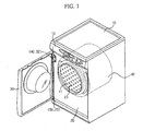
- FIG. 1 is a perspective view illustrating a drum washing machine in accordance with the present embodiment.
- the drum washing machine in accordance with the present embodiment includes a housing 10 forming an external appearance of the washing machine, a tub 12 installed in the housing 10, a drum 11 rotatably installed in the tub 12, an opening 21 formed through the housing 10 to be connected to the drum 11, and a door 30 to open and close the opening 21.
- a control panel 13 to control the washing method and the washing process of laundry according to a kind and amount of the laundry is installed on an upper portion of the housing 10.
- the housing 10 has a rectangular parallelepipedal shape, and the opening 21, through which laundry is put into the drum 11 or taken out of the drum 11, is formed through a front surface 20 of the housing 10.
- the door 30 rotated to open and close the opening 21 is hinged to the housing 10. Further, in order to improve the external appearance of the washing machine, when the door 30 closes the opening 21, the front surface 20 of the housing 10 is sunken to a designated depth so that the door 30 can be inserted into the housing 10 to the designated depth.
- the door 30 covers most of the front surface 20 of the housing 10, and thus has an increased size and weight. Thereby, a hinge structure to firmly endure the load of the door 30 and facilitate the connection of the door 30 to the housing 10 is required.
- a first hinge unit 40 and 32 which rotatably supports the door 30, is provided, and a second hinge unit 50 and 23, which is separated from the first hinge unit 40 and 32 and thus rotatably supports the door 30 together with the first hinge unit 40 and 32, is provided.
- the first hinge unit 40 and 32 supports an upper end of a left portion, for example, of the door 30, and the second hinge unit 50 and 23 supports a lower surface of the left portion of the door 30.
- the second hinge unit 50 and 23 axially supports the load of the door 30, thereby reducing the load transferred to a first hinge member 40.
- FIG. 2 is an exploded perspective view illustrating the first hinge unit 40 and 32 of the drum washing machine in accordance with the present embodiment.
- the first hinge unit 40 and 32 includes the first hinge member 40 forming an axis, and first hinge holes 32, into which parts of the hinge member 40 are respectively inserted, provided in the door 30.
- the first hinge member 40 includes a plurality of first hinge protrusions 41 connected to a rotary axis 60 of the door 30, first hinge bodies 42 connected to the first hinge protrusions 41 and fixed to the housing 10, and a plurality of first hinge hangers 43 protruded from a base hinge portion 44 to which the first hinge bodies 42 are fixed to fix the first hinge bodies 42 to the housing 10.
- space formation parts 31 to form a designated space are provided in the door 30.
- the plurality of first hinge holes 32, into which the hinge protrusions 41 are respectively inserted, are formed in the door 30 along the rotary axis 60 of the door 30.
- the first hinge holes 32 are symmetrical with respect to the space formation parts 31.
- a plurality of first hinge hanger grooves 22 to fix the first hinge member 40 to the housing 10 is formed in the housing 10. That is, the first hinge member 40 is fixed to the housing 10 by inserting the first hinge hangers 43 of the first hinge member 40 into the first hinge hanger grooves 22 formed in the housing 10.
- a first opening restriction member 33 which is separated from the rotary axis 60 of the door 30 to adjust an opening angle of the door 30, is provided in each of the space formation parts 31 of the door 30.
- the first hinge bodies 42 of the first hinge member 40 connected to the door 30 are respectively located in the space formation parts 31.
- the first opening restriction members 33 and the first hinge bodies 42 are referred to as a first opening restriction unit 33 and 42 to restrict the opening angle of the door 30. Accordingly, if the door 30 is opened at a designated angle ( ⁇ 1), the first opening restriction members 33 contact the first hinge bodies 42, and thus prevent the door 30 from being opened to more than the designated angle ( ⁇ 1). This structure will be described in detail below, with reference to FIGs. 4 and 5 .
- FIG. 3 is an exploded perspective view illustrating the second hinge unit of the drum washing machine in accordance with the present embodiment.
- the second hinge unit 50 and 23 is separated from the first hinge unit 40 and 32, and thus rotatably supports the door 30 together with the first hinge unit 40 and 32.
- the second hinge unit 50 and 23 includes a second hinge protrusion 50 provided on a lower surface of a left portion of the door 30, and a second hinge hole 23 to support the second hinge protrusion 50 inserted thereinto.
- the second hinge protrusion 50 and the second hinge hole 23 are provided along the rotary axis 60 of the door 30.
- the second hinge protrusion 50 is protruded from the lower surface of the door 30 in the direction toward the rotary axis 60 of the door 30.
- the hinge protrusion 50 has a cylindrical shape, and the second hinge hole 23 is formed in a lower portion of the housing 10 so that the second hinge protrusion 50 can be inserted into the second hinge hole 23 to support the door 30.
- the second hinge hole 23 has a designated depth, and is configured such that the inner diameter of the second hinge hole 23 is decreased from an upper portion thereof to a lower portion thereof (or the inner diameter of the second hinge hole 23 is increased from the lower portion thereof to the upper portion thereof).
- the door 30 can be tilted while fixing the tip of the second hinge protrusion 50 to the housing 10.
- the door 30 is easily hinged to the housing 10 by inserting the second hinge protrusion 50 into the second hinge hole 23 and then by easily inserting the first hinge hangers 43 (with reference to Fig. 2 ) into the first hinge hanger grooves 22 (with reference to FIG. 2 ).
- a second opening restriction unit 51 and 24 to restrict an opening angle of the door 30 is provided on the second hinge unit 50 and 23.
- the second opening restriction unit 51 and 24 includes a second opening restriction member 51 and a second hinge hanger 24.
- the second opening restriction member 51 is provided on a side surface of the second hinge protrusion 50. That is, the second opening restriction member 51 is protruded from the side surface of the second hinge protrusion 50.
- the second hinge hanger 24 is protruded from a side surface of the second hinge hole 23.
- the second opening restriction member 51 is formed integrally with the second hinge protrusion 50, and the second hinge hanger 24 is formed integrally with the housing 10.
- the second opening restriction member 51 contacts the second hinge hanger 24, and thus prevents the door 30 from being damaged due to a collision with the housing 10.
- the first opening restriction unit 33 and 42 is provided on the first hinge unit 40 and 32 and the door 30
- the second opening restriction unit 51 and 24 is provided on the second hinge unit 50 and 23, or both the first opening restriction unit 33 and 42 and the second opening restriction unit 51 and 24 are provided.
- first opening restriction unit 33 and 42 and the second opening restriction unit 51 and 24 are referred to as opening restriction units 33, 42, 51, and 24, both the first opening restriction unit 33 and 42 and the second opening restriction unit 51 and 24 are provided, and a sequential restriction of the opening angle of the door 30 by the first opening restriction unit 33 and 42 and the second opening restriction unit 51 and 24 will be described in detail.
- FIG. 4 is a sectional view illustrating the door in an opened state and the first opening restriction unit provided on the upper portion of the drum washing machine in accordance with the present embodiment.
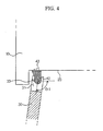
- FIG. 5 is a sectional view illustrating the door in the opened state and the second opening restriction unit provided on the lower portion of the drum washing machine in accordance with the present embodiment.
- the first opening restriction members 33 provided in the space formation parts 31 of the door 30 are supported by the first hinge bodies 42. Thereby, the door 30 is not opened to more than the designated angle ( ⁇ 1), and thus it is possible to prevent the door 30 from being damaged due to a collision with the housing 10.
- the second hinge protrusion 50 has a weaker rigidity than that of the first hinge member 40.
- the door 30 is opened at the designated angle ( ⁇ 1) under the condition that there is no designated interval (G) between the second opening restriction member 51 and the second hinge hanger 24, when the second hinge hanger 24 and the second opening restriction member 51 contact each other, torsion is applied to the second hinge protrusion 50, and thus the second hinge protrusion 50 may be easily damaged.
- the second opening restriction member 51 does not contact the second hinge hanging member 24, thus preventing the second hinge protrusion 50 having a weak structure from being damaged.
- the second opening restriction member 51 contacts the second hinge hanger 24, thus preventing the door 30 from being damaged due to a collision with the housing 10.
- the present embodiment provides a drum washing machine in which a worker may easily assemble a door with a housing, thus increasing a working efficiency.
- the drum washing machine of the present embodiment reduces load transferred to a first hinge unit of the door to prevent the first hinge unit from being twisted and damaged, and prevents the door from being tilted to effectively open and close the door.
- the drum washing machine of the present embodiment allows a first opening restriction unit and a second opening restriction unit to sequentially restrict the opening angle of the door, thus preventing a second hinge protrusion from being damaged.
Landscapes
- Engineering & Computer Science (AREA)
- Textile Engineering (AREA)
- Main Body Construction Of Washing Machines And Laundry Dryers (AREA)
- Hinges (AREA)
Claims (13)
- Machine à laver à tambour comprenant :un coffret (10) muni d'une surface avant rectangulaire (20) comportant une ouverture (21) à travers laquelle du linge est déposé dans la machine à laver ;une porte (30) reliée au coffret (10) pour ouvrir et fermer l'ouverture (21), la porte (30) recouvrant la surface avant (20) du coffret (10) ;une première unité de charnière (32, 40) reliant de manière rotative la porte (30) au coffret (10) ; etune seconde unité de charnière (23, 50) séparée de la première unité de charnière (32, 40) supportant en rotation la porte (30), en même temps que la première unité de charnière (32, 40),dans laquelle la porte (30) comporte une face latérale et une surface inférieure reliée à l'extrémité inférieure de la face latérale, ladite première unité de charnière (32, 40) étant prévue entre la face latérale de la porte (30) et le coffret (10),dans laquelle la seconde unité de charnière (23, 50) permet à la porte (30) d'être supportée sur le coffret (10), etdans laquelle la seconde unité de charnière (23, 50) est prévue sur l'axe de rotation (60) de la porte (30) et supporte axialement la charge de la porte (30),dans laquelle la seconde unité de charnière (23, 50) comporte une protubérance de charnière (50) et un trou de charnière (23) prévu dans le coffret (10) pour supporter ladite protubérance de charnière (50) insérée dans celui-ci, de sorte que la porte (30) est supportée sur le coffret (10),caractérisée en ce que la protubérance de charnière (50) de la seconde unité de charnière (23, 50) est prévue sur la surface inférieure de la porte (30).
- Machine à laver à tambour selon la revendication 1, dans laquelle la première unité de charnière (32, 40) est prévue sur une face de la porte (30) et la seconde unité de charnière (23, 50) est prévue en dessous de la première unité de charnière (32, 40).
- Machine à laver à tambour selon l'une des revendications précédentes, dans laquelle le diamètre intérieur du trou de charnière de la seconde unité de charnière (23, 50) augmente à partir de sa partie inférieure jusqu'à sa partie supérieure de sorte que la porte (30) peut être inclinée lorsqu'elle est fixée au coffret (10) en insérant la protubérance de charnière (50) dans ledit trou de charnière (23).
- Machine à laver à tambour selon l'une des revendications précédentes, dans laquelle la première unité de charnière (32, 40) comporte des premières protubérances de charnière (41) reliées à l'axe de rotation (60) de la porte (30), des premiers corps de charnière (42) reliés aux premières protubérances de charnière (41) et fixés au coffret (10), des premiers éléments de suspension de charnière (43) fixant les premiers corps de charnière (42) au coffret (10) et des premiers trous de charnière (32) formés dans la porte (30) pour supporter les premières protubérances de charnière (41) insérées dans ceux-ci.
- Machine à laver à tambour selon l'une des revendications précédentes, dans laquelle au moins une unité parmi la première unité de charnière (32, 40) et la seconde unité de charnière (23, 50) comporte une unité de limitation d'ouverture limitant l'angle d'ouverture de la porte (30).
- Machine à laver à tambour selon la revendication 5, dans laquelle l'unité de limitation d'ouverture comporte au moins une unité parmi une première unité de limitation d'ouverture (33, 42) et une seconde unité de limitation d'ouverture (24, 51), les première et seconde unités de limitation d'ouverture (24, 33, 42, 51) limitant respectivement l'angle d'ouverture de la porte (30) dans des plages différentes.
- Machine à laver à tambour selon la revendication 6, dans laquelle la première unité de limitation d'ouverture (33, 42) est prévue sur une face de la porte (30) et comporte des premiers éléments de limitation d'ouverture (33) prévus sur la porte (30) et des premiers corps de charnière (42) prévus sur la première unité de charnière (32, 42) et les premiers éléments de limitation d'ouverture (33) sont en contact avec les premiers corps de charnière (42) pour limiter l'angle d'ouverture de la porte (30) lorsque la porte (30) est ouverte d'un angle désigné (θ1).
- Machine à laver à tambour selon la revendication 6 ou 7, dans laquelle la protubérance de charnière (50) de la seconde unité de charnière (23, 50) est prévue sur l'axe de rotation (60) de la porte (30) et la seconde unité de limitation d'ouverture (24, 51) comporte un second élément de limitation d'ouverture (51) prévu de manière adjacente à la protubérance de charnière (50) de la seconde unité de charnière (23, 50) pour limiter l'angle d'ouverture de la porte (30) et un second élément de suspension de charnière (24) prévu dans le trou de charnière (23) de la seconde unité de charnière (23, 50) pour être en contact avec le second élément de limitation d'ouverture (51) lorsque la porte (30) tourne.
- Machine à laver à tambour selon la revendication 8, dans laquelle le second élément de limitation d'ouverture (51) est formé d'un seul tenant avec la protubérance de charnière (50) de la seconde unité de charnière (23, 50) et le second élément de suspension de charnière (24) est formé d'un seul tenant avec le trou de charnière (23) de la seconde unité de charnière (23, 50).
- Machine à laver à tambour selon la revendication 8 ou 9, dans laquelle la première unité de limitation d'ouverture (33, 42) limite l'angle d'ouverture de la porte (30) à un angle désigné (θ1) et lorsque la porte (30) est ouverte de l'angle désigné (θ1), un intervalle désigné (G) existe entre le second élément de limitation d'ouverture (51) et le second élément de suspension de charnière (24).
- Machine à laver à tambour selon l'une des revendications précédentes, dans laquelle la première unité de charnière (32, 40) relie de manière rotative la porte (30) au coffret (10) à l'extrémité supérieure de la porte (30) et supporte la porte (30) en rotation ; et
la seconde unité de charnière (23, 50) supporte en rotation la surface inférieure de la porte (30). - Machine à laver à tambour selon l'une des revendications 6 à 10, dans laquelle la première unité de limitation d'ouverture (33, 42) et la seconde unité de limitation d'ouverture (24, 52) limitent successivement l'angle d'ouverture de la porte (30).
- Machine à laver à tambour selon la revendication 12, dans laquelle la première unité de limitation d'ouverture (33, 42) limite l'angle d'ouverture de la porte (30) d'un angle désigné (θ1) et la seconde unité de limitation d'ouverture (24, 51) limite l'angle d'ouverture de la porte (30) lorsqu'un utilisateur force la porte (30) à s'ouvrir de plus de l'angle désigné (θ1) de sorte que la porte (30) ne peut pas entrer en collision avec le coffret (10).
Applications Claiming Priority (1)
| Application Number | Priority Date | Filing Date | Title |
|---|---|---|---|
| KR1020070033514A KR100845290B1 (ko) | 2007-04-05 | 2007-04-05 | 드럼세탁기 |
Publications (3)
| Publication Number | Publication Date |
|---|---|
| EP1978145A2 EP1978145A2 (fr) | 2008-10-08 |
| EP1978145A3 EP1978145A3 (fr) | 2009-12-23 |
| EP1978145B1 true EP1978145B1 (fr) | 2015-04-22 |
Family
ID=39592846
Family Applications (1)
| Application Number | Title | Priority Date | Filing Date |
|---|---|---|---|
| EP20080150361 Active EP1978145B1 (fr) | 2007-04-05 | 2008-01-17 | Machine à laver à tambour avec charnières de support |
Country Status (4)
| Country | Link |
|---|---|
| US (1) | US8322171B2 (fr) |
| EP (1) | EP1978145B1 (fr) |
| KR (1) | KR100845290B1 (fr) |
| CN (1) | CN101280504B (fr) |
Families Citing this family (16)
| Publication number | Priority date | Publication date | Assignee | Title |
|---|---|---|---|---|
| WO2010085117A2 (fr) * | 2009-01-23 | 2010-07-29 | 엘지전자 주식회사 | Machine de traitement du linge |
| US8444234B2 (en) * | 2009-07-31 | 2013-05-21 | Lg Electronics Inc. | Washing machine |
| TR200909201A2 (tr) * | 2009-12-08 | 2011-06-21 | Bsh Ev Aletleri̇ San. Ve Ti̇c. A.Ş. | Önden yüklemeli bir çamaşir makinesi |
| MX2010005581A (es) | 2010-05-19 | 2011-11-18 | Mabe Sa De Cv | Puerta de un solo vidrio para secadora. |
| US8936330B2 (en) * | 2010-12-23 | 2015-01-20 | Lg Electronics Inc. | Laundry treating apparatus |
| US8820861B2 (en) | 2010-12-23 | 2014-09-02 | Lg Electronics Inc. | Laundry treating apparatus |
| WO2012115467A2 (fr) * | 2011-02-24 | 2012-08-30 | Lg Electronics Inc. | Appareil de traitement du linge |
| CN103806252B (zh) * | 2012-11-07 | 2017-03-01 | 海尔集团公司 | 滚筒洗衣机 |
| KR102219934B1 (ko) * | 2014-03-28 | 2021-02-25 | 삼성전자주식회사 | 드럼세탁기 |
| USD767221S1 (en) * | 2015-03-04 | 2016-09-20 | Lg Electronics Inc. | Washing machine |
| WO2017133782A1 (fr) * | 2016-02-05 | 2017-08-10 | Arcelik Anonim Sirketi | Ensemble charnière à utiliser dans un appareil de traitement de linge |
| CN109208280B (zh) * | 2017-07-07 | 2021-05-11 | 青岛海尔洗涤电器有限公司 | 一种滚筒洗衣机 |
| US10890023B2 (en) * | 2017-10-17 | 2021-01-12 | Ncr Corporation | Safe enclosure hinge integrated stop |
| JP2019177226A (ja) * | 2019-07-19 | 2019-10-17 | パナソニックIpマネジメント株式会社 | ドラム式洗濯機 |
| EP4204622A2 (fr) | 2020-09-30 | 2023-07-05 | Monotony.AI, Inc. | Dispositifs de lavage et de séchage de linge autonomes, systèmes et méthodes d'utilisation |
| US11866970B2 (en) | 2020-12-07 | 2024-01-09 | Whirlpool Corporation | Fabric treatment machine hinge spacer |
Family Cites Families (17)
| Publication number | Priority date | Publication date | Assignee | Title |
|---|---|---|---|---|
| IT8034011V0 (it) * | 1980-02-25 | 1980-02-25 | Zanussi A Spa Industrie | Dispositivo di chiusura per macchine lavabiancheria. |
| IT1155278B (it) * | 1982-02-08 | 1987-01-28 | Smeg Elettrodomestici | Macchina lavabiancheria integrabile in un complesso di mobili |
| DE3301596A1 (de) * | 1983-01-19 | 1984-07-19 | Wilhelm Dr.-Ing. 5340 Bad Honnef Lepper | Behaelter, insbesondere waeschebehaelter |
| DE9014378U1 (de) | 1990-10-17 | 1990-12-20 | Zanker GmbH, 7400 Tübingen | Haushaltsgerät |
| GB9122079D0 (en) * | 1991-10-17 | 1991-11-27 | J E S Arnold Domestic Applianc | A door for a domestic electrical appliance |
| US5187837A (en) * | 1991-11-14 | 1993-02-23 | White Consolidated Industries, Inc. | Door hinge assembly |
| ES2154088B1 (es) | 1996-11-26 | 2001-10-01 | Balay Sa | Dispositivo para el anclaje abisagrado de puertas de electrodomesticos. |
| US5881576A (en) * | 1997-10-29 | 1999-03-16 | Maytag Corporation | Shroud mounted door |
| KR19990029441U (ko) * | 1997-12-29 | 1999-07-26 | 윤홍구 | 드럼 세탁기 도어의 개폐구조 |
| CN1314851C (zh) * | 2002-01-09 | 2007-05-09 | Lg电子株式会社 | 用于洗衣机和烘干机的门以及设有这种门的洗衣机和烘干机 |
| US6935712B2 (en) | 2002-02-14 | 2005-08-30 | U-Line Corporation | Refrigeration unit |
| KR100425126B1 (ko) * | 2002-03-13 | 2004-03-30 | 엘지전자 주식회사 | 드럼세탁기의 케이스-도어 링크장치 및 이를 조립하는 방법 |
| WO2005042891A1 (fr) | 2003-10-31 | 2005-05-12 | Arcelik Anonim Sirketi | Appareil domestique a charniere bidirectionnelle |
| DE102004060422B4 (de) | 2004-12-14 | 2008-04-24 | Miele & Cie. Kg | Haushaltgerät, wie beispielsweise eine Waschmaschine, ein Wäschetrockner oder dergleichen |
| KR101203547B1 (ko) * | 2005-04-15 | 2012-11-23 | 엘지전자 주식회사 | 세탁기의 전면부 구조 |
| CN2837338Y (zh) | 2005-07-21 | 2006-11-15 | 江苏海狮机械集团有限公司 | 工业洗衣机中门的锁紧装置 |
| US7617570B2 (en) * | 2006-03-22 | 2009-11-17 | Whirlpool Corporation | Double-pivot, constrained kinematic hinge for a front-loading laundry machine |
-
2007
- 2007-04-05 KR KR1020070033514A patent/KR100845290B1/ko active Active
-
2008
- 2008-01-16 US US12/007,899 patent/US8322171B2/en active Active
- 2008-01-17 EP EP20080150361 patent/EP1978145B1/fr active Active
- 2008-01-24 CN CN2008100038535A patent/CN101280504B/zh not_active Expired - Fee Related
Also Published As
| Publication number | Publication date |
|---|---|
| US8322171B2 (en) | 2012-12-04 |
| CN101280504B (zh) | 2012-06-06 |
| EP1978145A3 (fr) | 2009-12-23 |
| EP1978145A2 (fr) | 2008-10-08 |
| US20080245112A1 (en) | 2008-10-09 |
| KR100845290B1 (ko) | 2008-07-09 |
| CN101280504A (zh) | 2008-10-08 |
Similar Documents
| Publication | Publication Date | Title |
|---|---|---|
| EP1978145B1 (fr) | Machine à laver à tambour avec charnières de support | |
| EP2327824B1 (fr) | Machine à laver à tambour avec unités de charnière | |
| US8459754B2 (en) | Washing machine | |
| EP1747316B1 (fr) | Ensemble tambour pour lave-linge | |
| EP3190221B1 (fr) | Appareil de traitement du linge avec un accessoire de porte pour le détergent | |
| EP3339498B1 (fr) | Machine à laver | |
| EP2611958B1 (fr) | Hublot de porte structural pour porte d'appareil électroménager | |
| CN101319455B (zh) | 滚筒型洗衣机及门 | |
| AU2010206038B2 (en) | Washing machine | |
| KR100484795B1 (ko) | 드럼세탁기의 도어 | |
| EP2824233A1 (fr) | Machine à laver | |
| EP2000574B1 (fr) | Corps de cuve rotative et machine à laver de type à tambour doté de celui-ci | |
| KR100484830B1 (ko) | 드럼세탁기의 세제통 조립구조 | |
| EP2365118B1 (fr) | Machine à laver de type tambour | |
| KR102643352B1 (ko) | 의류처리장치 | |
| US11668123B2 (en) | Washing machine | |
| AU2020200534B2 (en) | Laundry treating apparatus | |
| US20050257577A1 (en) | Washing machine and method for assembling the same | |
| WO2020235125A1 (fr) | Machine à laver | |
| KR100511954B1 (ko) | 드럼세탁기의 도어 힌지 어셈블리 | |
| CN110241577B (zh) | 铰链及衣物处理装置 | |
| KR100847555B1 (ko) | 세탁기 | |
| KR101234038B1 (ko) | 드럼세탁기의 도어 | |
| US10253442B2 (en) | Top-loading type washing machine | |
| KR20250081389A (ko) | 의류처리장치 |
Legal Events
| Date | Code | Title | Description |
|---|---|---|---|
| PUAI | Public reference made under article 153(3) epc to a published international application that has entered the european phase |
Free format text: ORIGINAL CODE: 0009012 |
|
| AK | Designated contracting states |
Kind code of ref document: A2 Designated state(s): AT BE BG CH CY CZ DE DK EE ES FI FR GB GR HR HU IE IS IT LI LT LU LV MC MT NL NO PL PT RO SE SI SK TR |
|
| AX | Request for extension of the european patent |
Extension state: AL BA MK RS |
|
| PUAL | Search report despatched |
Free format text: ORIGINAL CODE: 0009013 |
|
| AK | Designated contracting states |
Kind code of ref document: A3 Designated state(s): AT BE BG CH CY CZ DE DK EE ES FI FR GB GR HR HU IE IS IT LI LT LU LV MC MT NL NO PL PT RO SE SI SK TR |
|
| AX | Request for extension of the european patent |
Extension state: AL BA MK RS |
|
| 17P | Request for examination filed |
Effective date: 20100525 |
|
| 17Q | First examination report despatched |
Effective date: 20100625 |
|
| AKX | Designation fees paid |
Designated state(s): DE FR GB |
|
| RAP1 | Party data changed (applicant data changed or rights of an application transferred) |
Owner name: SAMSUNG ELECTRONICS CO., LTD. |
|
| GRAP | Despatch of communication of intention to grant a patent |
Free format text: ORIGINAL CODE: EPIDOSNIGR1 |
|
| INTG | Intention to grant announced |
Effective date: 20141106 |
|
| GRAS | Grant fee paid |
Free format text: ORIGINAL CODE: EPIDOSNIGR3 |
|
| GRAA | (expected) grant |
Free format text: ORIGINAL CODE: 0009210 |
|
| AK | Designated contracting states |
Kind code of ref document: B1 Designated state(s): DE FR GB |
|
| REG | Reference to a national code |
Ref country code: GB Ref legal event code: FG4D |
|
| REG | Reference to a national code |
Ref country code: DE Ref legal event code: R096 Ref document number: 602008037768 Country of ref document: DE Effective date: 20150603 |
|
| REG | Reference to a national code |
Ref country code: FR Ref legal event code: PLFP Year of fee payment: 9 |
|
| REG | Reference to a national code |
Ref country code: DE Ref legal event code: R097 Ref document number: 602008037768 Country of ref document: DE |
|
| PLBE | No opposition filed within time limit |
Free format text: ORIGINAL CODE: 0009261 |
|
| STAA | Information on the status of an ep patent application or granted ep patent |
Free format text: STATUS: NO OPPOSITION FILED WITHIN TIME LIMIT |
|
| 26N | No opposition filed |
Effective date: 20160125 |
|
| REG | Reference to a national code |
Ref country code: FR Ref legal event code: PLFP Year of fee payment: 10 |
|
| REG | Reference to a national code |
Ref country code: FR Ref legal event code: PLFP Year of fee payment: 11 |
|
| PGFP | Annual fee paid to national office [announced via postgrant information from national office to epo] |
Ref country code: FR Payment date: 20181224 Year of fee payment: 12 Ref country code: GB Payment date: 20181220 Year of fee payment: 12 |
|
| GBPC | Gb: european patent ceased through non-payment of renewal fee |
Effective date: 20200117 |
|
| PG25 | Lapsed in a contracting state [announced via postgrant information from national office to epo] |
Ref country code: FR Free format text: LAPSE BECAUSE OF NON-PAYMENT OF DUE FEES Effective date: 20200131 Ref country code: GB Free format text: LAPSE BECAUSE OF NON-PAYMENT OF DUE FEES Effective date: 20200117 |
|
| PGFP | Annual fee paid to national office [announced via postgrant information from national office to epo] |
Ref country code: DE Payment date: 20241223 Year of fee payment: 18 |