EP1977978A1 - Packaging container - Google Patents
Packaging container Download PDFInfo
- Publication number
- EP1977978A1 EP1977978A1 EP08006894A EP08006894A EP1977978A1 EP 1977978 A1 EP1977978 A1 EP 1977978A1 EP 08006894 A EP08006894 A EP 08006894A EP 08006894 A EP08006894 A EP 08006894A EP 1977978 A1 EP1977978 A1 EP 1977978A1
- Authority
- EP
- European Patent Office
- Prior art keywords
- clamshell
- packaging container
- perforations
- clamshell half
- severed
- Prior art date
- Legal status (The legal status is an assumption and is not a legal conclusion. Google has not performed a legal analysis and makes no representation as to the accuracy of the status listed.)
- Granted
Links
- 238000004806 packaging method and process Methods 0.000 title claims abstract description 78
- 238000003466 welding Methods 0.000 claims 1
- 229920003002 synthetic resin Polymers 0.000 description 5
- 239000000057 synthetic resin Substances 0.000 description 5
- 239000011111 cardboard Substances 0.000 description 3
- -1 polyethylene terephthalate Polymers 0.000 description 3
- 229920000139 polyethylene terephthalate Polymers 0.000 description 3
- 239000005020 polyethylene terephthalate Substances 0.000 description 3
- 238000010438 heat treatment Methods 0.000 description 2
- 239000000463 material Substances 0.000 description 2
- 229920000049 Carbon (fiber) Polymers 0.000 description 1
- 239000004677 Nylon Substances 0.000 description 1
- 239000004793 Polystyrene Substances 0.000 description 1
- BZHJMEDXRYGGRV-UHFFFAOYSA-N Vinyl chloride Chemical compound ClC=C BZHJMEDXRYGGRV-UHFFFAOYSA-N 0.000 description 1
- 239000002390 adhesive tape Substances 0.000 description 1
- 239000004917 carbon fiber Substances 0.000 description 1
- 239000003365 glass fiber Substances 0.000 description 1
- VNWKTOKETHGBQD-UHFFFAOYSA-N methane Chemical compound C VNWKTOKETHGBQD-UHFFFAOYSA-N 0.000 description 1
- 238000000034 method Methods 0.000 description 1
- 238000012986 modification Methods 0.000 description 1
- 230000004048 modification Effects 0.000 description 1
- 229920001778 nylon Polymers 0.000 description 1
- 229920002223 polystyrene Polymers 0.000 description 1
- 238000007789 sealing Methods 0.000 description 1
- 238000007666 vacuum forming Methods 0.000 description 1
Images







Classifications
-
- B—PERFORMING OPERATIONS; TRANSPORTING
- B65—CONVEYING; PACKING; STORING; HANDLING THIN OR FILAMENTARY MATERIAL
- B65D—CONTAINERS FOR STORAGE OR TRANSPORT OF ARTICLES OR MATERIALS, e.g. BAGS, BARRELS, BOTTLES, BOXES, CANS, CARTONS, CRATES, DRUMS, JARS, TANKS, HOPPERS, FORWARDING CONTAINERS; ACCESSORIES, CLOSURES, OR FITTINGS THEREFOR; PACKAGING ELEMENTS; PACKAGES
- B65D75/00—Packages comprising articles or materials partially or wholly enclosed in strips, sheets, blanks, tubes or webs of flexible sheet material, e.g. in folded wrappers
- B65D75/04—Articles or materials wholly enclosed in single sheets or wrapper blanks
- B65D75/20—Articles or materials wholly enclosed in single sheets or wrapper blanks in sheets or blanks doubled around contents and having their opposed free margins united, e.g. by pressure-sensitive adhesive, crimping, heat-sealing, or welding
- B65D75/22—Articles or materials wholly enclosed in single sheets or wrapper blanks in sheets or blanks doubled around contents and having their opposed free margins united, e.g. by pressure-sensitive adhesive, crimping, heat-sealing, or welding the sheet or blank being recessed to accommodate contents
-
- B—PERFORMING OPERATIONS; TRANSPORTING
- B65—CONVEYING; PACKING; STORING; HANDLING THIN OR FILAMENTARY MATERIAL
- B65D—CONTAINERS FOR STORAGE OR TRANSPORT OF ARTICLES OR MATERIALS, e.g. BAGS, BARRELS, BOTTLES, BOXES, CANS, CARTONS, CRATES, DRUMS, JARS, TANKS, HOPPERS, FORWARDING CONTAINERS; ACCESSORIES, CLOSURES, OR FITTINGS THEREFOR; PACKAGING ELEMENTS; PACKAGES
- B65D75/00—Packages comprising articles or materials partially or wholly enclosed in strips, sheets, blanks, tubes or webs of flexible sheet material, e.g. in folded wrappers
- B65D75/52—Details
- B65D75/58—Opening or contents-removing devices added or incorporated during package manufacture
- B65D75/5827—Tear-lines provided in a wall portion
- B65D75/5833—Tear-lines provided in a wall portion for tearing out a portion of the wall
- B65D75/5844—Tear-lines provided in a wall portion for tearing out a portion of the wall the portion of the wall being a narrow strip, e.g. between lines of weakness
-
- B—PERFORMING OPERATIONS; TRANSPORTING
- B65—CONVEYING; PACKING; STORING; HANDLING THIN OR FILAMENTARY MATERIAL
- B65D—CONTAINERS FOR STORAGE OR TRANSPORT OF ARTICLES OR MATERIALS, e.g. BAGS, BARRELS, BOTTLES, BOXES, CANS, CARTONS, CRATES, DRUMS, JARS, TANKS, HOPPERS, FORWARDING CONTAINERS; ACCESSORIES, CLOSURES, OR FITTINGS THEREFOR; PACKAGING ELEMENTS; PACKAGES
- B65D75/00—Packages comprising articles or materials partially or wholly enclosed in strips, sheets, blanks, tubes or webs of flexible sheet material, e.g. in folded wrappers
- B65D75/52—Details
- B65D75/58—Opening or contents-removing devices added or incorporated during package manufacture
- B65D75/66—Inserted or applied tearing-strings or like flexible elements
-
- Y—GENERAL TAGGING OF NEW TECHNOLOGICAL DEVELOPMENTS; GENERAL TAGGING OF CROSS-SECTIONAL TECHNOLOGIES SPANNING OVER SEVERAL SECTIONS OF THE IPC; TECHNICAL SUBJECTS COVERED BY FORMER USPC CROSS-REFERENCE ART COLLECTIONS [XRACs] AND DIGESTS
- Y10—TECHNICAL SUBJECTS COVERED BY FORMER USPC
- Y10S—TECHNICAL SUBJECTS COVERED BY FORMER USPC CROSS-REFERENCE ART COLLECTIONS [XRACs] AND DIGESTS
- Y10S229/00—Envelopes, wrappers, and paperboard boxes
- Y10S229/924—Means to facilitate gripping a tear strip
- Y10S229/926—Pull tab located in a seam
-
- Y—GENERAL TAGGING OF NEW TECHNOLOGICAL DEVELOPMENTS; GENERAL TAGGING OF CROSS-SECTIONAL TECHNOLOGIES SPANNING OVER SEVERAL SECTIONS OF THE IPC; TECHNICAL SUBJECTS COVERED BY FORMER USPC CROSS-REFERENCE ART COLLECTIONS [XRACs] AND DIGESTS
- Y10—TECHNICAL SUBJECTS COVERED BY FORMER USPC
- Y10S—TECHNICAL SUBJECTS COVERED BY FORMER USPC CROSS-REFERENCE ART COLLECTIONS [XRACs] AND DIGESTS
- Y10S229/00—Envelopes, wrappers, and paperboard boxes
- Y10S229/927—Means for tearing or breaking rigid or semirigid thermoplastic container
Definitions
- the present disclosure relates to a packaging container and particularly to a packaging container that accommodates a packaged object in a room defined between a first clamshell and a second clamshell half, which fit to each other.
- Clamshell packaging has been known as a general packaging form that enables shops to hang products for sale such as stationery, small electrical devices, dry cell batteries and memory card in good-looking manners. Many clamshell packaging cases are transparent for making the products accommodated inside highly visible, and, in addition, they offer high degrees of security in protecting the products.
- a line of perforations be provided in the rear side of the clamshell packaging case around the accommodated object (refer to, for example, Japanese Laid-Open Patent Publication No. 2002-128140 ).
- the clamshell packaging case disclosed in Japanese Laid-Open Patent Publication No. 2002-128140 enables a user to open the packaging case by tearing it along the line of perforations without using a tool like scissors or a cutter.
- the clamshell packaging case disclosed in Japanese Laid-Open Patent Publication No. 2002-128140 enables a user to open the packaging case by tearing it along the line of perforations, which is provided around the accommodated object, and to take the object out.
- the packaging case can break off in an unintended direction away from the line of perforations.
- Another problem has been that the tearing of the packaging case along the line of perforations can form a sharp edge even if the packaging case itself is opened successfully along the line of perforations.
- the present disclosure is to solve the above mentioned problems, and the object of the present disclosure is to provide a clamshell packaging container that enables easy and safe manual opening.
- a packaging container comprises a first clamshell half, a second clamshell half, a connecting portion that connects an edge of the first clamshell half with an edge of the second clamshell half, a sealed portion that fastens the first clamshell half and the second clamshell half to each other, the sealed portion being located at the edge of the packaging container on a side opposite to the connecting portion, and a severed portion that is provided in at least one of the first clamshell half and the second clamshell half between the sealed portion and a packaged object, which is accommodated in a room created between the first clamshell half and the second clamshell half when the clamshell halves are fitted to each other, and that is severed off for opening the packaging container.
- a packaging container according to the present disclosure comprises a severed part that is severed for opening the packaging container. As a result, a user can easily open the packaging container just by manually pulling and removing the severed part without using scissors or a cutter.
- FIGS. 1 - 4 a clamshell packaging case 1, which is one embodiment of the present disclosure, is described with reference to FIGS. 1 - 4 .
- the structural outline of the clamshell packaging case 1 is described with reference to FIGS. 1 - 4 .
- the clamshell packaging case 1 is a vertically rectangular packaging container in front view, and it is transparent because its material is a synthetic resin such as polyethylene terephthalate, vinyl chloride or polystyrene.
- the clamshell packaging case 1 accommodates, for example, a small electronic product like a tape printer 6, stationary, an electronic calculator, a dry cell battery or a memory card, and the packaged product is hung from a rack of a store for sale.
- the clamshell packaging case 1 comprises a first clamshell 2 and a second clamshell 3, which are connected to each other by a foldable fold part 4 and are to fit to each other.
- the first clamshell 2 is vertically rectangular in front view and constitutes the front face of the clamshell packaging case 1.
- the second clamshell 3 is also vertically rectangular in front view and constitutes the rear face of the clamshell packaging case 1.
- an object to be packaged for example, a tape printer 6, is placed between the first clamshell 2 and the second clamshell 3.
- a card board 5 which carries on its front and rear faces a description and an advertisement of the product can be placed together.
- the card board 5 has an opening 51, through which the packaged object, i.e., the tape printer 6, can pass, and another opening 55, through which a hook (not shown) for hanging the package from a sale rack can pass.
- the first clamshell 2 and the second clamshell 3 are sealed at a sealed part 24 as shown in FIG. 1 .
- a packaged object with a card board 5 is sandwiched between the first clamshell 2 and the second clamshell 3, which are then sealed at the sealed part 24 for completing the clamshell packaging case 1, enclosing the packaged object.
- the first clamshell 2 and the second clamshell 3 be made to fit into each other. Therefore, the first clamshell 2 and the second clamshell 3 that include fitting parts to fit each other are detailed in the following.
- the first clamshell 2 is a transparent case made of a synthetic resin such as polyethylene terephthalate, and it has a vertically rectangular form in front view as shown in these drawings.
- the first clamshell 2 has a first storage space 21 at its lower part in front view for accommodating a packaged object, i.e., a tape printer 6.
- the first storage space 21 protrudes outward, but it is recessed if viewed from the inside of the first clamshell 2, and the first storage space 21 has a capacity that can accommodate the upper half of the packaged object, i.e., the tape printer 6.
- the first clamshell 2 is provided with a fitting groove 22 inwardly adjacent to and along the circumference of the first clamshell 2.
- the fitting groove 22 is laid out in a rectangle in front view, and it has a "U"-shape in cross-sectional view.
- the fitting groove 22 is recessed if viewed from the inside of the first clamshell 2 but is raised if viewed from outside.
- the fitting groove 22 is provided with engaging concave parts 23 in the inner wall on the upper side, the right side and the left sides of the fitting groove 22 as shown in FIG. 2 , three of them on each side.
- Each engaging concave part is recessed in a "U"-shape in cross-sectional view, has a predetermined length.
- the first clamshell 2 is provided with an opening 25 at a position below the upper part of the fitting groove 22 as shown in FIG. 2 , which opening is for the hook (not shown), which is used for hanging the package from a rack for sale.
- the first clamshell 2 is provided with the sealed part 24 above and along the upper part of the fitting groove 22 and in parallel with the upper edge of the first clamshell 2, the sealed part 24 extending linearly with a predetermined width.
- the second clamshell 3 is a transparent case made of a synthetic resin such as polyethylene terephthalate, and it has a vertically rectangular form in front view as shown in these drawings.
- the second clamshell 3 has a second storage space 31 at its lower part in front view for accommodating the packaged object, i.e., the tape printer 6.
- the second storage space 31 protrudes outward, but it is recessed if viewed from the inside of the second clamshell 3, and the second storing space 31 has a capacity that can accommodate the lower half of the packaged object, i.e., the tape printer 6.
- the second clamshell 3 is provided with a fitting convex part 32 inwardly adjacent to and along the circumference of the second clamshell 3.
- the fitting convex part 32 has an inverted "U"-shape in cross-sectional view, and it is laid out in a rectangle in front view in such a way that the fitting convex part 32 is raised if viewed from the inside (front side) of the second clamshell 3 but is recessed if viewed from the outside (rear side).
- the fitting convex part 32 is provided with engaging convex parts 33 on the outer wall on the upper side, the right side and the left sides of the fitting convex part 32 as shown in FIG. 3 , three of them on each side.
- Each engaging convex part 33 is raised in an inverted "U"-shape in cross-sectional view, and it has a predetermined length and a height, which configuration enables each engaging convex part to fittingly enter an above described corresponding engaging concave part 23.
- the second clamshell 3 is provided with an opening 35 at a position below the upper part of the fitting convex part 32 as shown in FIG. 3 , which opening is for a hook (not shown), which is used for hanging the package from a rack for sale.
- the second clamshell 3 is provided with a sealed part 34 above and along the upper part of the fitting convex part 32 and in parallel with the upper edge of the second clamshell 3, the sealed part 34 extending linearly with a predetermined width.
- the second clamshell 3 is provided with two lines of perforations 36A, 36B at a position between the sealed part 34 and the fitting convex part 32 and adjacent to and in parallel with the sealed part 34 as shown in FIG. 3 .
- the part delimited by these two lines of perforations 36A, 36B is a severed part 37.
- the severed part 37 does not need to be arranged in parallel to the sealed part 34 as long as it is positioned sufficiently adjacent to the sealed part 34 to prevent the second clamshell 3 from coming off from the first clamshell 2 while the severed part 37 is still being pulled and severed for opening the clamshell packaging case.
- the second clamshell 3 is also provided with a foot-like support 38 at the lower part thereof (in FIG. 3 ).
- the foot-like support 38 which protrudes with a predetermined width and a predetermined height, supports the clamshell packaging case 1 when the clamshell packaging case is placed on a flat surface.
- the clamshell packaging case 1 is securely closed even at its right and left edges because the first clamshell 2 and the second clamshell 3 are fittingly fixed by the provision of the engaging concave parts 23 and the engaging convex parts 33.
- the severed part 37 is the part delimited by the two lines of perforations 36A, 36B, which are provided in parallel with the sealed part 34 and adjacent to the upper edge of the second clamshell 3, which constitutes the rear face of the clamshell packaging case 1.
- the severed part is torn off along the lines of perforations 36A and perforations 36B as shown in FIG. 8 .
- the user pulls the second clamshell 3 away from the first clamshell 2, disengaging one from the other for opening the clamshell packaging case 1.
- the user takes out the packaged object, i.e., the tape printer 6.
- the packaged object i.e., the tape printer 6.
- part that had formed the perforations 36A of the second clamshell 3 still remains on the flat part of the first clamshell 2 (where the flat face of the first clamshell 2 is in contact with the flat face of the second clamshell 3). Therefore, this remaining part of the perforations 36A never projects into the fitting groove 22 and never acquires a form of saw blade, so safety is maintained.
- the removal of the severed part 37 can be performed in a clean manner because the severed part 37 is provided adjacent to the sealed part 34.
- the two lines of perforations make the pulling force applied on the severed part 37 act evenly on both the edges of the severed part 37. As a result, the severed part 37 is torn through neatly without any break. Furthermore, since the severed part 37 is provided in the second clamshell 3, which constitutes the rear side of the clamshell packaging case 1, the first clamshell 2, which constitutes the front side, is kept good-looking for front side without disturbance, so it is still suitable for advertisement use.
- the second clamshell 3 may be provided with both the lines of perforations 36A, 36B or at least one line of perforations 36A at a position that comes into contact with the flat part of the first clamshell 2.
- the clamshell packaging case 1 which has the above described structure, is produced in a one-piece body that comprises the first clamshell 2 and the second clamshell 3 by vacuum forming, in which process, a sheet of a synthetic resin is heated to a forming temperature, stretched onto a mold, and held against the mold by applying vacuum.
- This variation of clamshell packaging case 1 comprises fold parts 27 provided on the right and left edges of the first clamshell 2, each fold part 27 having a predetermined length and a predetermined width and being folded over the rear side of the packaging case (side of the second clamshell 3) as shown in FIGS. 9 - 11 .
- fold parts 27 provided on the right and left edges of the first clamshell 2, each fold part 27 having a predetermined length and a predetermined width and being folded over the rear side of the packaging case (side of the second clamshell 3) as shown in FIGS. 9 - 11 .
- the fold parts 27 When the second clamshell 3 is to be separated from the first clamshell 2, these fold parts 27 are forcefully opened outward for disengaging the edges of the second clamshell 3 from the fold parts 27 of the first clamshell 2. Therefore, in the fitted condition where the first clamshell 2 and the second clamshell 3 are fitted to each other, the fold parts 27 have a sufficient strength for maintaining the first clamshell 2 and the second clamshell 3 securely in their fitted condition, but these fold parts allow disengagement without resisting to the opening action taken by the user.
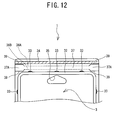
- continuous cuts 39 each of which extends inward continuously for a predetermined length are provided at the right and left ends of the severed part 37, which is delimited by the two lines of perforations 36A, 36B and is positioned parallel to the sealed part 34 and adjacent to the upper edge of the second clamshell 3 as shown in FIG. 12 .
- picking tabs 37A each of which is wider than the width defined by the two parallel lines of perforations 36A, 36B are provided at the right and left end parts of the severed part 37, where the end parts are delimited by the above mentioned continuous cuts 39. Therefore, the picking tabs 37A, which are delimited by the continuous cuts 39 with a predetermined length in advance, are easily picked and lifted, so the severed part 37 can be easily severed and removed.
- the second variation has no severed part 37 that is delimited by two lines of perforations 36A, 36B as described above at the part where the first clamshell 2 and the second clamshell 3 are in contact with each other.
- the second clamshell 3 is provided with a continuous cut 36C in advance at the part where it comes into contact with the first clamshell 2, and the cut 36C is closed and held by a strip of adhesive tape 40.
- the tape 40 is removed, and then the second clamshell 3 is disengaged and separated from the first clamshell 2.
- a third variation of severed part 37 is described in reference to FIG. 14 .
- a strip of film 41 is provided between the severed part 37, which is delimited by the two lines of perforations 36A, 36B, and the first clamshell 2, in the condition where the first clamshell 2 and the second clamshell 3 are in contact with each other as shown in FIG. 14 .
- the strip of film 41 has the same length and approximately same width as the severed part 37 and extends along the severed part 37, for making the severing and removing of the severed part 37 easy along the lines of perforations 36A, 36B. When the clamshell packaging case is to be opened, this film is pulled along with the severed part.
- the film 41 has a tensile strength sufficient for withstanding the force applied for tearing off the severed part along the lines of perforations 36A, 36B, and it is made from such a material as synthetic resin, nylon, glass fiber or carbon fiber.
- the clamshell packaging case 1 comprises the first clamshell 2 and the second clamshell 3 that are formed in a one-piece body.
- the first clamshell 2 and the second clamshell 3 can be each formed as a separate part and then joined to complete the clamshell packaging case 1.
- the first clamshell 2 and the second clamshell 3 may be welded both at their upper and lower edges.
- the two lines of perforations 36A, 36B and the severed part 37 may be provided, instead, to the first clamshell 2, which constitutes the front face of the clamshell packaging case 1.
- the two lines of perforations 36A, 36B and the severed part 37 may be provided both at the upper and lower edges of the clamshell packaging case 1, respectively.
Landscapes
- Engineering & Computer Science (AREA)
- Mechanical Engineering (AREA)
- Packages (AREA)
Abstract
Description
- The present disclosure relates to a packaging container and particularly to a packaging container that accommodates a packaged object in a room defined between a first clamshell and a second clamshell half, which fit to each other.
- Clamshell packaging has been known as a general packaging form that enables shops to hang products for sale such as stationery, small electrical devices, dry cell batteries and memory card in good-looking manners. Many clamshell packaging cases are transparent for making the products accommodated inside highly visible, and, in addition, they offer high degrees of security in protecting the products.
- Furthermore, for providing users easy access to the product accommodated in the clamshell packaging case after their purchase, there is a suggestion that a line of perforations be provided in the rear side of the clamshell packaging case around the accommodated object (refer to, for example, Japanese Laid-Open Patent Publication No.
2002-128140 2002-128140 - The clamshell packaging case disclosed in Japanese Laid-Open Patent Publication No.
2002-128140 - The present disclosure is to solve the above mentioned problems, and the object of the present disclosure is to provide a clamshell packaging container that enables easy and safe manual opening.
- For solving the above object, a packaging container according to the invention comprises a first clamshell half, a second clamshell half, a connecting portion that connects an edge of the first clamshell half with an edge of the second clamshell half, a sealed portion that fastens the first clamshell half and the second clamshell half to each other, the sealed portion being located at the edge of the packaging container on a side opposite to the connecting portion, and a severed portion that is provided in at least one of the first clamshell half and the second clamshell half between the sealed portion and a packaged object, which is accommodated in a room created between the first clamshell half and the second clamshell half when the clamshell halves are fitted to each other, and that is severed off for opening the packaging container.
As described above, a packaging container according to the present disclosure comprises a severed part that is severed for opening the packaging container. As a result, a user can easily open the packaging container just by manually pulling and removing the severed part without using scissors or a cutter. - An exemplary embodiment of the invention will be described below in detail with reference to the accompanying drawings in which:
-
FIG. 1 is a perspective view of a clamshell packaging case; -
FIG. 2 is a front view of the clamshell packaging case; -
FIG. 3 is a rear view of the clamshell packaging case; -
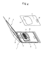
FIG. 4 is a perspective view of the clamshell packaging case in its opened condition; -
FIG. 5 is a cross-sectional view taken along line I-I in the direction indicated by arrows inFIG. 2 ; -
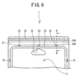
FIG. 6 is an enlarged partial view of an upper part of the rear side (second clamshell half) of the clamshell packaging case; -
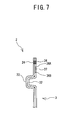
FIG. 7 is a cross-sectional view taken along line II-II in the direction indicated by arrows inFIG. 6 , showing a fitted condition where the fitting groove of the first clamshell and the fitting convex part of the second clamshell are fitted with each other and sealed condition; -
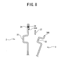
FIG. 8 is a cross-sectional view showing a condition where the fitting groove of the first clamshell and the fitting convex part of the second clamshell are disengaged from each other; -
FIG. 9 is a front view of another clamshell packaging case as a variation; -
FIG. 10 is a rear view of the clamshell packaging case shown inFIG. 9 ; -
FIG. 11 is a cross-sectional view taken along line III-III in the direction indicated by arrows inFIG. 9 ; -
FIG. 12 is an enlarged partial view of an upper part of the rear side (second clamshell half) of a clamshell packaging case as a first alternative; -
FIG. 13 is a cross-sectional view showing a fitted condition where the fitting groove of the first clamshell and the fitting convex part of the second clamshell of a second variation are fitted with each other and showing their sealed condition; and -
FIG. 14 is a cross-sectional view showing a fitted condition where the fitting groove of the first clamshell and the fitting convex part of the second clamshell of a third alternative are fitted with each other and showing their sealed condition. - Now, a
clamshell packaging case 1, which is one embodiment of the present disclosure, is described with reference toFIGS. 1 - 4 . - At first, the structural outline of the
clamshell packaging case 1 is described with reference toFIGS. 1 - 4 . As shown in these drawings, theclamshell packaging case 1 is a vertically rectangular packaging container in front view, and it is transparent because its material is a synthetic resin such as polyethylene terephthalate, vinyl chloride or polystyrene. Theclamshell packaging case 1 accommodates, for example, a small electronic product like atape printer 6, stationary, an electronic calculator, a dry cell battery or a memory card, and the packaged product is hung from a rack of a store for sale. - The
clamshell packaging case 1 comprises afirst clamshell 2 and asecond clamshell 3, which are connected to each other by afoldable fold part 4 and are to fit to each other. Thefirst clamshell 2 is vertically rectangular in front view and constitutes the front face of theclamshell packaging case 1. Thesecond clamshell 3 is also vertically rectangular in front view and constitutes the rear face of theclamshell packaging case 1. - As shown in
FIG. 4 , an object to be packaged, for example, atape printer 6, is placed between thefirst clamshell 2 and thesecond clamshell 3. In addition to the packaged object, a card board 5, which carries on its front and rear faces a description and an advertisement of the product can be placed together. The card board 5 has anopening 51, through which the packaged object, i.e., thetape printer 6, can pass, and anotheropening 55, through which a hook (not shown) for hanging the package from a sale rack can pass. Then, thefirst clamshell 2 and thesecond clamshell 3 are sealed at a sealedpart 24 as shown inFIG. 1 .
As described above, in principle, a packaged object with a card board 5 is sandwiched between thefirst clamshell 2 and thesecond clamshell 3, which are then sealed at the sealedpart 24 for completing theclamshell packaging case 1, enclosing the packaged object. Furthermore, for making the sealing of thefirst clamshell 2 and thesecond clamshell 3 more secure, it is preferable that thefirst clamshell 2 and thesecond clamshell 3 be made to fit into each other. Therefore, thefirst clamshell 2 and thesecond clamshell 3 that include fitting parts to fit each other are detailed in the following. - Now, the structure of the
first clamshell 2 is described in reference toFIG. 2 andFIG. 4 . Thefirst clamshell 2 is a transparent case made of a synthetic resin such as polyethylene terephthalate, and it has a vertically rectangular form in front view as shown in these drawings. In addition, thefirst clamshell 2 has afirst storage space 21 at its lower part in front view for accommodating a packaged object, i.e., atape printer 6. Thefirst storage space 21 protrudes outward, but it is recessed if viewed from the inside of thefirst clamshell 2, and thefirst storage space 21 has a capacity that can accommodate the upper half of the packaged object, i.e., thetape printer 6. - In addition, the
first clamshell 2 is provided with afitting groove 22 inwardly adjacent to and along the circumference of thefirst clamshell 2. Thefitting groove 22 is laid out in a rectangle in front view, and it has a "U"-shape in cross-sectional view. Thefitting groove 22 is recessed if viewed from the inside of thefirst clamshell 2 but is raised if viewed from outside. Furthermore, thefitting groove 22 is provided with engagingconcave parts 23 in the inner wall on the upper side, the right side and the left sides of thefitting groove 22 as shown inFIG. 2 , three of them on each side. Each engaging concave part is recessed in a "U"-shape in cross-sectional view, has a predetermined length. Moreover, thefirst clamshell 2 is provided with anopening 25 at a position below the upper part of thefitting groove 22 as shown inFIG. 2 , which opening is for the hook (not shown), which is used for hanging the package from a rack for sale. In addition, thefirst clamshell 2 is provided with thesealed part 24 above and along the upper part of thefitting groove 22 and in parallel with the upper edge of thefirst clamshell 2, thesealed part 24 extending linearly with a predetermined width. After thefirst clamshell 2 and thesecond clamshell 3 are fittingly joined to each other, thesealed part 24 of thefirst clamshell 2 is welded to the corresponding part of thesecond clamshell 3 by heating or ultrasonic wave. - Now, the structure of the
second clamshell 3 is described in reference toFIGS. 3 and4 . Thesecond clamshell 3 is a transparent case made of a synthetic resin such as polyethylene terephthalate, and it has a vertically rectangular form in front view as shown in these drawings. In addition, thesecond clamshell 3 has asecond storage space 31 at its lower part in front view for accommodating the packaged object, i.e., thetape printer 6. Thesecond storage space 31 protrudes outward, but it is recessed if viewed from the inside of thesecond clamshell 3, and thesecond storing space 31 has a capacity that can accommodate the lower half of the packaged object, i.e., thetape printer 6. - In addition, the
second clamshell 3 is provided with afitting convex part 32 inwardly adjacent to and along the circumference of thesecond clamshell 3. Thefitting convex part 32 has an inverted "U"-shape in cross-sectional view, and it is laid out in a rectangle in front view in such a way that the fittingconvex part 32 is raised if viewed from the inside (front side) of thesecond clamshell 3 but is recessed if viewed from the outside (rear side). Furthermore, thefitting convex part 32 is provided with engagingconvex parts 33 on the outer wall on the upper side, the right side and the left sides of the fitting convexpart 32 as shown inFIG. 3 , three of them on each side. Each engagingconvex part 33 is raised in an inverted "U"-shape in cross-sectional view, and it has a predetermined length and a height, which configuration enables each engaging convex part to fittingly enter an above described corresponding engagingconcave part 23. Moreover, thesecond clamshell 3 is provided with anopening 35 at a position below the upper part of the fittingconvex part 32 as shown inFIG. 3 , which opening is for a hook (not shown), which is used for hanging the package from a rack for sale. In addition, thesecond clamshell 3 is provided with a sealedpart 34 above and along the upper part of the fittingconvex part 32 and in parallel with the upper edge of thesecond clamshell 3, the sealedpart 34 extending linearly with a predetermined width. After thefirst clamshell 2 and thesecond clamshell 3 are fittingly joined to each other, the sealedpart 34 of thesecond clamshell 3 is welded to the sealedpart 24 of thefirst clamshell 2 by heating or ultrasonic wave. - Moreover, the
second clamshell 3 is provided with two lines ofperforations part 34 and the fittingconvex part 32 and adjacent to and in parallel with the sealedpart 34 as shown inFIG. 3 . The part delimited by these two lines ofperforations part 37. By the way, the severedpart 37 does not need to be arranged in parallel to the sealedpart 34 as long as it is positioned sufficiently adjacent to the sealedpart 34 to prevent thesecond clamshell 3 from coming off from thefirst clamshell 2 while the severedpart 37 is still being pulled and severed for opening the clamshell packaging case. - As shown in
FIGS. 1 and3 , thesecond clamshell 3 is also provided with a foot-like support 38 at the lower part thereof (inFIG. 3 ). The foot-like support 38, which protrudes with a predetermined width and a predetermined height, supports theclamshell packaging case 1 when the clamshell packaging case is placed on a flat surface. - Now, the fitting of the engaging
concave parts 23 of thefirst clamshell 2 and the engagingconvex parts 33 of thesecond clamshell 3 is described in reference toFIG. 5 . When thefirst clamshell 2 and thesecond clamshell 3 are brought to fit into each other, all the engagingconvex parts 33, which are provided on the fittingconvex part 32 of thesecond clamshell 3, come into fittingly contact with all the engagingconcave parts 23, which are provided in thefitting groove 22 of thefirst clamshell 2, as shown inFIG. 5 . In the condition where the engagingconvex parts 33 and the engagingconcave parts 23 are fittingly fixed to each other, thefirst clamshell 2 and thesecond clamshell 3 are also fixed to each other, preventing even their right and left sides from being opened. In other words, after the sealedparts first clamshell 2 and thesecond clamshell 3 are welded to each other at the edge located on the side opposite to where thefold part 4 is located, theclamshell packaging case 1 is securely closed even at its right and left edges because thefirst clamshell 2 and thesecond clamshell 3 are fittingly fixed by the provision of the engagingconcave parts 23 and the engagingconvex parts 33. - Now, the opening of the
clamshell packaging case 1, which has the above described structure, is described in reference toFIGS. 6 - 8 . - As shown in
FIGS. 6 and7 , the severedpart 37 is the part delimited by the two lines ofperforations part 34 and adjacent to the upper edge of thesecond clamshell 3, which constitutes the rear face of theclamshell packaging case 1. When the user takes hold of either one of the right and left ends of the severedpart 37 with his fingers and lifts it and pulls it toward the other end, the severed part is torn off along the lines ofperforations 36A andperforations 36B as shown inFIG. 8 . After the removal of the severedpart 37, the user pulls thesecond clamshell 3 away from thefirst clamshell 2, disengaging one from the other for opening theclamshell packaging case 1. Then, the user takes out the packaged object, i.e., thetape printer 6. As shown inFIG. 8 , even after the removal of the severedpart 37, part that had formed theperforations 36A of thesecond clamshell 3 still remains on the flat part of the first clamshell 2 (where the flat face of thefirst clamshell 2 is in contact with the flat face of the second clamshell 3). Therefore, this remaining part of theperforations 36A never projects into thefitting groove 22 and never acquires a form of saw blade, so safety is maintained. Furthermore, the removal of the severedpart 37 can be performed in a clean manner because the severedpart 37 is provided adjacent to the sealedpart 34. The two lines of perforations, which are provided in parallelism, make the pulling force applied on the severedpart 37 act evenly on both the edges of the severedpart 37. As a result, the severedpart 37 is torn through neatly without any break. Furthermore, since the severedpart 37 is provided in thesecond clamshell 3, which constitutes the rear side of theclamshell packaging case 1, thefirst clamshell 2, which constitutes the front side, is kept good-looking for front side without disturbance, so it is still suitable for advertisement use. By the way, thesecond clamshell 3 may be provided with both the lines ofperforations perforations 36A at a position that comes into contact with the flat part of thefirst clamshell 2. Theclamshell packaging case 1, which has the above described structure, is produced in a one-piece body that comprises thefirst clamshell 2 and thesecond clamshell 3 by vacuum forming, in which process, a sheet of a synthetic resin is heated to a forming temperature, stretched onto a mold, and held against the mold by applying vacuum. - Now, a variation of
clamshell packaging case 1, which has the above described structure, is described in reference toFIGS. 9 - 11 . This variation ofclamshell packaging case 1 comprises foldparts 27 provided on the right and left edges of thefirst clamshell 2, each foldpart 27 having a predetermined length and a predetermined width and being folded over the rear side of the packaging case (side of the second clamshell 3) as shown inFIGS. 9 - 11 . With the provision of thesefold parts 27, now, the side edges of thesecond clamshell 3 are bound to thefirst clamshell 2 by thefold parts 27 as shown inFIG. 11 , providing a protection against accidental opening. When thesecond clamshell 3 is to be separated from thefirst clamshell 2, thesefold parts 27 are forcefully opened outward for disengaging the edges of thesecond clamshell 3 from thefold parts 27 of thefirst clamshell 2. Therefore, in the fitted condition where thefirst clamshell 2 and thesecond clamshell 3 are fitted to each other, thefold parts 27 have a sufficient strength for maintaining thefirst clamshell 2 and thesecond clamshell 3 securely in their fitted condition, but these fold parts allow disengagement without resisting to the opening action taken by the user. - Now, a first variation of severed
part 37 is described in reference toFIG. 12 . In this variation,continuous cuts 39 each of which extends inward continuously for a predetermined length are provided at the right and left ends of the severedpart 37, which is delimited by the two lines ofperforations part 34 and adjacent to the upper edge of thesecond clamshell 3 as shown inFIG. 12 . Furthermore, pickingtabs 37A each of which is wider than the width defined by the two parallel lines ofperforations part 37, where the end parts are delimited by the above mentionedcontinuous cuts 39. Therefore, the pickingtabs 37A, which are delimited by thecontinuous cuts 39 with a predetermined length in advance, are easily picked and lifted, so the severedpart 37 can be easily severed and removed. - Now, a second variation of severed
part 37 is described in reference toFIG. 13 . As shown inFIG. 13 the second variation has no severedpart 37 that is delimited by two lines ofperforations first clamshell 2 and thesecond clamshell 3 are in contact with each other. Instead, thesecond clamshell 3 is provided with acontinuous cut 36C in advance at the part where it comes into contact with thefirst clamshell 2, and thecut 36C is closed and held by a strip ofadhesive tape 40. In this design, for opening theclamshell packaging case 1, thetape 40 is removed, and then thesecond clamshell 3 is disengaged and separated from thefirst clamshell 2. - Now, a third variation of severed
part 37 is described in reference toFIG. 14 . In this third variation, a strip offilm 41 is provided between thesevered part 37, which is delimited by the two lines ofperforations first clamshell 2, in the condition where thefirst clamshell 2 and thesecond clamshell 3 are in contact with each other as shown inFIG. 14 . In this variation, the strip offilm 41 has the same length and approximately same width as thesevered part 37 and extends along the severedpart 37, for making the severing and removing of the severedpart 37 easy along the lines ofperforations
When the clamshell packaging case is to be opened, this film is pulled along with the severed part. The pulling of the film facilitates the complete removal of the severed part. For this purpose, thefilm 41 has a tensile strength sufficient for withstanding the force applied for tearing off the severed part along the lines ofperforations - The present invention is not limited to the above described embodiments, and various modifications are possible. For example, in the above example, the
clamshell packaging case 1 comprises thefirst clamshell 2 and thesecond clamshell 3 that are formed in a one-piece body. However, thefirst clamshell 2 and thesecond clamshell 3 can be each formed as a separate part and then joined to complete theclamshell packaging case 1. As an alternative, thefirst clamshell 2 and thesecond clamshell 3 may be welded both at their upper and lower edges. Furthermore, the two lines ofperforations part 37 may be provided, instead, to thefirst clamshell 2, which constitutes the front face of theclamshell packaging case 1. Moreover, the two lines ofperforations part 37 may be provided both at the upper and lower edges of theclamshell packaging case 1, respectively.
Claims (10)
- A packaging container (1) comprising:a first clamshell half (2),a second clamshell half (3),a connecting portion (4) that connects an edge of the first clamshell half (2) with an edge of the second clamshell half (3),a sealed portion (24,34) that fastens the first clamshell half (2) and the second clamshell half (3) to each other, the sealed portion (24,34) being located at the edge of the packaging container (1) on a side opposite to the connecting portion (4), anda severed portion (37) that is provided in at least one of the first clamshell half (2) and the second clamshell half (3) between the sealed portion (24,34) and a packaged object (6), which is accommodated in a room (21,31) created between the first clamshell half (2) and the second clamshell half (3) when the clamshell halves (2,3) are fitted to each other, for severing off for opening the packaging container (1).
- The packaging container (1) according to claim 1, wherein the sealed portion (24,34) is sealed by welding.
- The packaging container (1) according to claim 1 or 2, wherein the severed portion (37) is provided adjacent to the sealed portion (24,34).
- The packaging container (1) according to any one of claims 1 to 3, wherein the severed portion (37) is defined by two lines of perforations (36A, 36B) which are provided in parallel.
- The packaging container (1) according to claim 4, wherein at least one of the two lines of perforations (36A, 36B) is provided at the part where the first clamshell half (2) and the second clamshell half (3) are in contact with each other.
- The packaging container (1) according to claim 4 or 5, further comprising a picking tab (37A) that is provided at at least one of the ends of the lines of perforations (36A, 36B) in the direction where the lines of perforations (36A, 36B) delimiting the severed portion (37) extend and that is defined by cuts which have a continuous, predetermined length, the picking tab (37A) having a width larger than the gap between the two parallel lines of perforations (36A, 36B) delimiting the severed portion (37).
- The packaging container (1) according to any one of claims 4 to 6, further comprising a strip of film (41) that is provided between the first clamshell half (2) and the second clamshell half (3) and along the severed portion (37), for making the severed portion (37) to be torn off easily, which is delimited by the two parallel lines of perforations (36A, 36B).
- The packaging container (1) according to any one of claims 1 to 7, further comprising fitting portions (22,32) that are provided at the circumference portion of the packaging container (1) and make the first clamshell half (2) and the second clamshell half (3) fit to each other, wherein
the first clamshell half (2) and the second clamshell half (3) are made to fit to each other by the fitting portions (22,32). - The packaging container (1) according to any one of claims 1 to 8, wherein the connecting portion (4) is a foldable fold portion (4).
- The packaging container (1) according to any one of claims 1 to 9, wherein the severed portion (37) is provided in either one of the first clamshell half (2) and the second clamshell half (3) that forms a rear side of the packaging container (1).
Applications Claiming Priority (1)
| Application Number | Priority Date | Filing Date | Title |
|---|---|---|---|
| JP2007101050A JP5125189B2 (en) | 2007-04-06 | 2007-04-06 | Packaging container |
Publications (2)
| Publication Number | Publication Date |
|---|---|
| EP1977978A1 true EP1977978A1 (en) | 2008-10-08 |
| EP1977978B1 EP1977978B1 (en) | 2010-09-22 |
Family
ID=39591361
Family Applications (1)
| Application Number | Title | Priority Date | Filing Date |
|---|---|---|---|
| EP08006894A Not-in-force EP1977978B1 (en) | 2007-04-06 | 2008-04-04 | Packaging container |
Country Status (5)
| Country | Link |
|---|---|
| US (1) | US7753205B2 (en) |
| EP (1) | EP1977978B1 (en) |
| JP (1) | JP5125189B2 (en) |
| CN (1) | CN101279662B (en) |
| DE (1) | DE602008002620D1 (en) |
Cited By (1)
| Publication number | Priority date | Publication date | Assignee | Title |
|---|---|---|---|---|
| GB2473891A (en) * | 2009-09-24 | 2011-03-30 | Roger Bromley | Container and opening means |
Families Citing this family (16)
| Publication number | Priority date | Publication date | Assignee | Title |
|---|---|---|---|---|
| US20100176020A1 (en) * | 2009-01-13 | 2010-07-15 | Tek Packaging LLC | Packaging with perforated opening strip |
| US20110106697A1 (en) | 2009-10-31 | 2011-05-05 | Target Brands, Inc. | Transaction product assembly with remote controlled article |
| US9221588B2 (en) * | 2009-11-04 | 2015-12-29 | Tracfone Wireless, Inc. | Slider device display package |
| US20110240644A1 (en) * | 2010-04-05 | 2011-10-06 | Steven Donald Kimmell | Thermoplastic containers with easy access defined by laser-induced rupturable areas |
| US20120005994A1 (en) * | 2010-07-09 | 2012-01-12 | Display Pack, Inc. | Thermoformed package with tamper evident seal |
| US8899434B2 (en) | 2010-11-24 | 2014-12-02 | Transparent Container Co., Inc. | Three-dimensionally hinged clamshell packaging system having a standing feature |
| CN102795406A (en) * | 2011-05-26 | 2012-11-28 | 邦你包企业股份有限公司 | Assembly packaging box with double-section type film dismounting function |
| US20120312817A1 (en) * | 2011-06-10 | 2012-12-13 | Tzu-Chen Yang | Box with two tearing stages for receiving an element |
| AU2011378451B2 (en) * | 2011-10-05 | 2015-09-24 | Colgate-Palmolive Company | Packaged oral care implement and package |
| US8800768B2 (en) | 2012-05-31 | 2014-08-12 | Milwaukee Electric Tool Corporation | Clamshell packaging |
| USD751379S1 (en) * | 2014-01-28 | 2016-03-15 | Bosch Automotive Service Solutions Inc. | Scan tool package |
| JP6047110B2 (en) * | 2014-02-28 | 2016-12-21 | Thk株式会社 | Package |
| US10029838B2 (en) * | 2015-03-17 | 2018-07-24 | Sonoco Development, Inc. | Clamshell package and method of forming the same |
| USD931737S1 (en) * | 2018-09-21 | 2021-09-28 | Amazon Technologies, Inc. | Gift card holder |
| USD874944S1 (en) * | 2018-10-05 | 2020-02-11 | Thrifty Drug Stores, Inc. | Cardboardless blister package for pills |
| GB2626381A (en) * | 2023-01-23 | 2024-07-24 | James Cropper 3D Products Ltd | Closure mechanism |
Citations (5)
| Publication number | Priority date | Publication date | Assignee | Title |
|---|---|---|---|---|
| GB191415698A (en) * | 1914-07-01 | 1915-02-11 | Robert Weir Green | Improvements in and relating to Boxes and Folders for Handkerchiefs and other Goods. |
| US3197120A (en) * | 1964-05-14 | 1965-07-27 | George C Sparks | Clamshell envelope |
| US6227369B1 (en) * | 1999-10-29 | 2001-05-08 | Sony Corporation | Clamshell package including both permanent and resealable fastening structure |
| WO2006102210A2 (en) | 2005-03-24 | 2006-09-28 | Hewlett-Packard Development Company, L.P. | Memory module clamshell package |
| US20060278551A1 (en) * | 2005-06-10 | 2006-12-14 | Mark Iv Industries Corp. | Shielded retail packaging for transponder |
Family Cites Families (22)
| Publication number | Priority date | Publication date | Assignee | Title |
|---|---|---|---|---|
| JPS5473172U (en) * | 1977-10-29 | 1979-05-24 | ||
| US4266666A (en) * | 1979-12-21 | 1981-05-12 | American Can Company | Blister package |
| US4574951A (en) * | 1984-12-17 | 1986-03-11 | Champion International Corporation | Reclosable package |
| US4739883A (en) * | 1987-02-20 | 1988-04-26 | Placon Corporation | Reclosable display package |
| JPS63175066U (en) * | 1987-03-26 | 1988-11-14 | ||
| US5009894A (en) * | 1988-03-07 | 1991-04-23 | Baker Cummins Pharmaceuticals, Inc. | Arrangement for and method of administering a pharmaceutical preparation |
| US5209354A (en) * | 1992-02-11 | 1993-05-11 | Newell Operating Company | Reusable blister package |
| US5443154A (en) * | 1993-09-27 | 1995-08-22 | Oscar Mayer Foods Corporation | Easy separating package and method |
| US5447232A (en) * | 1994-11-09 | 1995-09-05 | Chow; Jessie | Tool holder |
| EP0771736A1 (en) * | 1995-10-30 | 1997-05-07 | Plastofilm Industries, Inc. | Tamper evident thermoformed package |
| EP0929468B1 (en) * | 1997-07-15 | 2003-12-10 | Koninklijke Philips Electronics N.V. | Blister pack |
| JP2000079965A (en) * | 1998-09-02 | 2000-03-21 | Fuji Seal Inc | Case |
| US6213303B1 (en) * | 1999-11-30 | 2001-04-10 | Color Prelude, Inc. | Fluid or volatile cosmetic sampler package for subscription rate magazine insertion |
| JP2001225828A (en) * | 2000-02-15 | 2001-08-21 | Mitsubishi Plastics Ind Ltd | Molded container and container forming body |
| JP4326661B2 (en) * | 2000-03-10 | 2009-09-09 | 相互印刷紙器株式会社 | Paper blister pack |
| JP2002128140A (en) | 2000-10-25 | 2002-05-09 | Sony Corp | Package |
| US6920980B2 (en) * | 2002-06-24 | 2005-07-26 | Hewlett-Packard Development Company, L.P. | Container |
| JP2004051133A (en) * | 2002-07-17 | 2004-02-19 | Sony Corp | Clamshell pack |
| US7819279B2 (en) * | 2002-08-14 | 2010-10-26 | International Molded Packaging Corporation | Latchable container system |
| JP2005126103A (en) * | 2003-10-23 | 2005-05-19 | Sanyo Electric Co Ltd | Blister case |
| US20060096886A1 (en) * | 2004-11-05 | 2006-05-11 | Morrison David J | Package/container for batteries |
| US7389907B2 (en) * | 2005-12-07 | 2008-06-24 | Weyerhaeuser Company | Tri-fold blister card with opening mechanism |
-
2007
- 2007-04-06 JP JP2007101050A patent/JP5125189B2/en active Active
-
2008
- 2008-03-20 CN CN200810086615.5A patent/CN101279662B/en not_active Expired - Fee Related
- 2008-03-20 US US12/077,642 patent/US7753205B2/en active Active
- 2008-04-04 DE DE602008002620T patent/DE602008002620D1/en active Active
- 2008-04-04 EP EP08006894A patent/EP1977978B1/en not_active Not-in-force
Patent Citations (5)
| Publication number | Priority date | Publication date | Assignee | Title |
|---|---|---|---|---|
| GB191415698A (en) * | 1914-07-01 | 1915-02-11 | Robert Weir Green | Improvements in and relating to Boxes and Folders for Handkerchiefs and other Goods. |
| US3197120A (en) * | 1964-05-14 | 1965-07-27 | George C Sparks | Clamshell envelope |
| US6227369B1 (en) * | 1999-10-29 | 2001-05-08 | Sony Corporation | Clamshell package including both permanent and resealable fastening structure |
| WO2006102210A2 (en) | 2005-03-24 | 2006-09-28 | Hewlett-Packard Development Company, L.P. | Memory module clamshell package |
| US20060278551A1 (en) * | 2005-06-10 | 2006-12-14 | Mark Iv Industries Corp. | Shielded retail packaging for transponder |
Cited By (1)
| Publication number | Priority date | Publication date | Assignee | Title |
|---|---|---|---|---|
| GB2473891A (en) * | 2009-09-24 | 2011-03-30 | Roger Bromley | Container and opening means |
Also Published As
| Publication number | Publication date |
|---|---|
| JP2008254799A (en) | 2008-10-23 |
| US7753205B2 (en) | 2010-07-13 |
| CN101279662B (en) | 2011-10-26 |
| CN101279662A (en) | 2008-10-08 |
| EP1977978B1 (en) | 2010-09-22 |
| US20080245694A1 (en) | 2008-10-09 |
| JP5125189B2 (en) | 2013-01-23 |
| DE602008002620D1 (en) | 2010-11-04 |
Similar Documents
| Publication | Publication Date | Title |
|---|---|---|
| EP1977978B1 (en) | Packaging container | |
| TWI228479B (en) | Packaging unit, packaging unit and article combination, packaging unit containing an article, and method for facilitating opening a packaging unit | |
| CN102076572A (en) | Protective container for razor | |
| ES2398431T3 (en) | Removable lid container with unauthorized opening protection | |
| CN109311576B (en) | Reclosable battery package | |
| JP5898533B2 (en) | Product delivery box for courier | |
| EP2763911B1 (en) | Packaged oral care implement and a method of packaging | |
| WO2002042168A1 (en) | Container for photographs or the like | |
| US20220242641A1 (en) | Packaging made of cellulose material and opening method | |
| JP7246124B2 (en) | Wet sheet package | |
| JP7472215B2 (en) | Packaging Containers | |
| JP4237035B2 (en) | Sanitary tissue paper packaging bags | |
| EP2342141B1 (en) | A blister-type packaging unit having a weakened region to be torn | |
| JP2007153383A (en) | Tissue carton pack | |
| ITBO980043A1 (en) | OPENABLE AND CLOSABLE PACKAGING FOR FOOD PRODUCTS, INP ARTICULAR BAKERY PRODUCTS, SUCH AS RUSKS, BISCUITS AND SIMILAR | |
| EP1074481A1 (en) | A flexible bag having a tear off band for easy opening | |
| CN210455532U (en) | Packing box | |
| JP3174499U (en) | Cardboard box | |
| CN215664904U (en) | Packing box | |
| CN221069306U (en) | Tearing-open type food-grade plastic packaging bag | |
| KR20140045201A (en) | Dispenser of adhesive tape for wrapping box | |
| JP2006298448A (en) | Rolled packaging material storage carton | |
| JP4343017B2 (en) | Plastic outer bag and package comprising the same | |
| JP3108836U (en) | Food wrap paper box | |
| KR200461674Y1 (en) | Packaging case |
Legal Events
| Date | Code | Title | Description |
|---|---|---|---|
| PUAI | Public reference made under article 153(3) epc to a published international application that has entered the european phase |
Free format text: ORIGINAL CODE: 0009012 |
|
| AK | Designated contracting states |
Kind code of ref document: A1 Designated state(s): AT BE BG CH CY CZ DE DK EE ES FI FR GB GR HR HU IE IS IT LI LT LU LV MC MT NL NO PL PT RO SE SI SK TR |
|
| AX | Request for extension of the european patent |
Extension state: AL BA MK RS |
|
| 17P | Request for examination filed |
Effective date: 20090312 |
|
| AKX | Designation fees paid |
Designated state(s): BE DE FR GB |
|
| GRAP | Despatch of communication of intention to grant a patent |
Free format text: ORIGINAL CODE: EPIDOSNIGR1 |
|
| GRAC | Information related to communication of intention to grant a patent modified |
Free format text: ORIGINAL CODE: EPIDOSCIGR1 |
|
| GRAS | Grant fee paid |
Free format text: ORIGINAL CODE: EPIDOSNIGR3 |
|
| GRAA | (expected) grant |
Free format text: ORIGINAL CODE: 0009210 |
|
| AK | Designated contracting states |
Kind code of ref document: B1 Designated state(s): BE DE FR GB |
|
| REG | Reference to a national code |
Ref country code: GB Ref legal event code: FG4D |
|
| REF | Corresponds to: |
Ref document number: 602008002620 Country of ref document: DE Date of ref document: 20101104 Kind code of ref document: P |
|
| PLBE | No opposition filed within time limit |
Free format text: ORIGINAL CODE: 0009261 |
|
| STAA | Information on the status of an ep patent application or granted ep patent |
Free format text: STATUS: NO OPPOSITION FILED WITHIN TIME LIMIT |
|
| 26N | No opposition filed |
Effective date: 20110623 |
|
| REG | Reference to a national code |
Ref country code: DE Ref legal event code: R097 Ref document number: 602008002620 Country of ref document: DE Effective date: 20110623 |
|
| REG | Reference to a national code |
Ref country code: FR Ref legal event code: PLFP Year of fee payment: 9 |
|
| REG | Reference to a national code |
Ref country code: FR Ref legal event code: PLFP Year of fee payment: 10 |
|
| REG | Reference to a national code |
Ref country code: FR Ref legal event code: PLFP Year of fee payment: 11 |
|
| PGFP | Annual fee paid to national office [announced via postgrant information from national office to epo] |
Ref country code: GB Payment date: 20190326 Year of fee payment: 12 Ref country code: FR Payment date: 20190320 Year of fee payment: 12 |
|
| PGFP | Annual fee paid to national office [announced via postgrant information from national office to epo] |
Ref country code: BE Payment date: 20190325 Year of fee payment: 12 |
|
| PGFP | Annual fee paid to national office [announced via postgrant information from national office to epo] |
Ref country code: DE Payment date: 20190318 Year of fee payment: 12 |
|
| REG | Reference to a national code |
Ref country code: DE Ref legal event code: R119 Ref document number: 602008002620 Country of ref document: DE |
|
| PG25 | Lapsed in a contracting state [announced via postgrant information from national office to epo] |
Ref country code: FR Free format text: LAPSE BECAUSE OF NON-PAYMENT OF DUE FEES Effective date: 20200430 Ref country code: DE Free format text: LAPSE BECAUSE OF NON-PAYMENT OF DUE FEES Effective date: 20201103 |
|
| REG | Reference to a national code |
Ref country code: BE Ref legal event code: MM Effective date: 20200430 |
|
| PG25 | Lapsed in a contracting state [announced via postgrant information from national office to epo] |
Ref country code: BE Free format text: LAPSE BECAUSE OF NON-PAYMENT OF DUE FEES Effective date: 20200430 |
|
| GBPC | Gb: european patent ceased through non-payment of renewal fee |
Effective date: 20200404 |
|
| PG25 | Lapsed in a contracting state [announced via postgrant information from national office to epo] |
Ref country code: GB Free format text: LAPSE BECAUSE OF NON-PAYMENT OF DUE FEES Effective date: 20200404 |