EP1976161A2 - Method of determining master and slaves by communication capability of network nodes - Google Patents
Method of determining master and slaves by communication capability of network nodes Download PDFInfo
- Publication number
- EP1976161A2 EP1976161A2 EP08159424A EP08159424A EP1976161A2 EP 1976161 A2 EP1976161 A2 EP 1976161A2 EP 08159424 A EP08159424 A EP 08159424A EP 08159424 A EP08159424 A EP 08159424A EP 1976161 A2 EP1976161 A2 EP 1976161A2
- Authority
- EP
- European Patent Office
- Prior art keywords
- node
- information
- status information
- synchronization
- node apparatus
- Prior art date
- Legal status (The legal status is an assumption and is not a legal conclusion. Google has not performed a legal analysis and makes no representation as to the accuracy of the status listed.)
- Withdrawn
Links
- 238000004891 communication Methods 0.000 title claims abstract description 110
- 238000000034 method Methods 0.000 title claims description 27
- 238000005070 sampling Methods 0.000 claims description 32
- 238000012546 transfer Methods 0.000 claims description 14
- 230000004044 response Effects 0.000 claims description 10
- RWSOTUBLDIXVET-UHFFFAOYSA-N Dihydrogen sulfide Chemical compound S RWSOTUBLDIXVET-UHFFFAOYSA-N 0.000 claims description 8
- 230000005540 biological transmission Effects 0.000 description 41
- 238000012545 processing Methods 0.000 description 40
- 238000010586 diagram Methods 0.000 description 18
- 238000002654 craniosacral therapy Methods 0.000 description 16
- 238000010374 somatic cell nuclear transfer Methods 0.000 description 16
- 101100424823 Arabidopsis thaliana TDT gene Proteins 0.000 description 7
- 229920002451 polyvinyl alcohol Polymers 0.000 description 7
- 238000005516 engineering process Methods 0.000 description 3
- 239000011295 pitch Substances 0.000 description 3
- 230000001360 synchronised effect Effects 0.000 description 3
- AWSBQWZZLBPUQH-UHFFFAOYSA-N mdat Chemical compound C1=C2CC(N)CCC2=CC2=C1OCO2 AWSBQWZZLBPUQH-UHFFFAOYSA-N 0.000 description 2
- 238000012986 modification Methods 0.000 description 2
- 230000004048 modification Effects 0.000 description 2
- 230000003287 optical effect Effects 0.000 description 2
- 230000008054 signal transmission Effects 0.000 description 2
- 239000000203 mixture Substances 0.000 description 1
- 238000011160 research Methods 0.000 description 1
- 230000033764 rhythmic process Effects 0.000 description 1
- JUJBNYBVVQSIOU-UHFFFAOYSA-M sodium;4-[2-(4-iodophenyl)-3-(4-nitrophenyl)tetrazol-2-ium-5-yl]benzene-1,3-disulfonate Chemical compound [Na+].C1=CC([N+](=O)[O-])=CC=C1N1[N+](C=2C=CC(I)=CC=2)=NC(C=2C(=CC(=CC=2)S([O-])(=O)=O)S([O-])(=O)=O)=N1 JUJBNYBVVQSIOU-UHFFFAOYSA-M 0.000 description 1
- 230000005236 sound signal Effects 0.000 description 1
- 238000011144 upstream manufacturing Methods 0.000 description 1
Images


Classifications
-
- H—ELECTRICITY
- H04—ELECTRIC COMMUNICATION TECHNIQUE
- H04L—TRANSMISSION OF DIGITAL INFORMATION, e.g. TELEGRAPHIC COMMUNICATION
- H04L69/00—Network arrangements, protocols or services independent of the application payload and not provided for in the other groups of this subclass
- H04L69/24—Negotiation of communication capabilities
-
- H—ELECTRICITY
- H04—ELECTRIC COMMUNICATION TECHNIQUE
- H04H—BROADCAST COMMUNICATION
- H04H60/00—Arrangements for broadcast applications with a direct linking to broadcast information or broadcast space-time; Broadcast-related systems
- H04H60/02—Arrangements for generating broadcast information; Arrangements for generating broadcast-related information with a direct linking to broadcast information or to broadcast space-time; Arrangements for simultaneous generation of broadcast information and broadcast-related information
- H04H60/04—Studio equipment; Interconnection of studios
-
- H—ELECTRICITY
- H04—ELECTRIC COMMUNICATION TECHNIQUE
- H04L—TRANSMISSION OF DIGITAL INFORMATION, e.g. TELEGRAPHIC COMMUNICATION
- H04L12/00—Data switching networks
- H04L12/28—Data switching networks characterised by path configuration, e.g. LAN [Local Area Networks] or WAN [Wide Area Networks]
- H04L12/40—Bus networks
- H04L12/403—Bus networks with centralised control, e.g. polling
-
- H—ELECTRICITY
- H04—ELECTRIC COMMUNICATION TECHNIQUE
- H04L—TRANSMISSION OF DIGITAL INFORMATION, e.g. TELEGRAPHIC COMMUNICATION
- H04L41/00—Arrangements for maintenance, administration or management of data switching networks, e.g. of packet switching networks
-
- H—ELECTRICITY
- H04—ELECTRIC COMMUNICATION TECHNIQUE
- H04L—TRANSMISSION OF DIGITAL INFORMATION, e.g. TELEGRAPHIC COMMUNICATION
- H04L49/00—Packet switching elements
- H04L49/90—Buffering arrangements
-
- H—ELECTRICITY
- H04—ELECTRIC COMMUNICATION TECHNIQUE
- H04H—BROADCAST COMMUNICATION
- H04H60/00—Arrangements for broadcast applications with a direct linking to broadcast information or broadcast space-time; Broadcast-related systems
- H04H60/76—Arrangements characterised by transmission systems other than for broadcast, e.g. the Internet
- H04H60/81—Arrangements characterised by transmission systems other than for broadcast, e.g. the Internet characterised by the transmission system itself
- H04H60/93—Wired transmission systems
- H04H60/95—Wired transmission systems for local area
-
- H—ELECTRICITY
- H04—ELECTRIC COMMUNICATION TECHNIQUE
- H04L—TRANSMISSION OF DIGITAL INFORMATION, e.g. TELEGRAPHIC COMMUNICATION
- H04L12/00—Data switching networks
- H04L12/28—Data switching networks characterised by path configuration, e.g. LAN [Local Area Networks] or WAN [Wide Area Networks]
- H04L12/40—Bus networks
- H04L12/40052—High-speed IEEE 1394 serial bus
Definitions
- the present invention relates generally to a communication control apparatus preferably for use in a network such as a LAN (Local Area Network). More particularly, the present invention relates to a communication control apparatus that stores, for each of node apparatuses connected to the network, information representative of synchronization signal transmission and reception capabilities and synchronization signal transmission/reception setting status, and sets master and slaves of the synchronization signal appropriately and simply with reference to pieces of the stored information.
- LAN Local Area Network
- MIDI Musical Instrument Digital Interface
- the above-mentioned prior-art MIDI performance systems have a data transfer rate as low as 31.25 Kpbs, being incapable of constructing a system in which music is performed while transmitting sample data by use of a sampler having a sampling clock of 44.1 KHz.
- a music performance system capable of providing high-speed data transfer may be constructed by use of a high-speed interface (having data transfer rates up to 10 through 50 Mbps) such as USB (Universal Serial Bus) or IEEE 1394.
- a high-speed interface having data transfer rates up to 10 through 50 Mbps
- USB Universal Serial Bus
- IEEE 1394 IEEE 1394.
- a first communication control apparatus for setting a plurality of node apparatuses involved in a network to either of a transmitter and a receiver of synchronization information circulated through the network to synchronize the node apparatuses with each other.
- a storage device memorizes capability information representing either of an active capability to transmit the synchronization information and a passive capability to receive the synchronization information, owned by each of the node apparatuses.
- An indicating device indicates the active capabilities and the passive capabilities owned by the node apparatuses involved in the network according to the memorized capability information.
- a specifying device is operated in association with the indicated active capabilities and the passive capabilities of the node apparatuses for outputting status information effective to specify each node apparatus to a transmitter or a receiver of the synchronization information.
- a plurality of memory blocks are provided in correspondence to the plurality of the node apparatuses to memorize status information of the corresponding node apparatuses.
- a registering device registers each of the outputted status information into each memory block to set the corresponding node apparatus to a transmitter of the synchronization information when the status information specifies the transmitter, and to set the corresponding node apparatus to a receiver of the synchronization information when the status information specifies the receiver.
- the indicating device indicates the capability of transmission or reception on the basis of the synchronization capability information stored in the storage device for each of the plurality of node apparatuses.
- the user refers to the indication made by the indicating device and specifies the transmission or the reception of synchronization information for each node apparatus through the specifying device.
- Synchronization status information indicative of the transmission of synchronization information is written to the memory block corresponding to the node apparatus for which the transmission of synchronization information has been specified.
- Synchronization status information indicative of the reception of synchronization information is written to the memory block corresponding to the node apparatus for which the reception of synchronization information has been specified. Consequently, the user can simply and surely specify the transmission/reception of synchronization information for each node according to the indication made by the indicating device, thereby providing the transmission/reception setting as specified by the user.
- a second communication control apparatus for setting a plurality of node apparatuses including a first node apparatus and a second node apparatus involved in a network to either of a transmitter and a receiver of synchronization information circulated through the network to synchronize the node apparatuses with each other.
- a storage device memorizes common master information effective to specify the first node apparatus to a transmitter of synchronization information commonly used throughout the network.
- a determining device operates based on the memorized common master information for outputting status information effective to determine the second node apparatus to a receiver of the synchronization information transmitted from the first node apparatus.
- a memory block is provided in correspondence to the second node apparatus to memorize status information of the second node apparatus.
- a registering device registers the outputted status information into the memory block to set the second node apparatus to a receiver of the synchronization information.
- the storage device stores the common master information for specifying the first node apparatus as a transmitter of synchronization information common to the network.
- the determining device determines, for the second node apparatus, the reception of synchronization information from the first node apparatus on the basis of the common master information stored in the storage device. Synchronization status information indicative of the reception of synchronization signal is written to the memory block according to the determination made by the determining device. Consequently, the reception of synchronization information can be automatically determined on the basis of the common master information, allowing the setting of reception in accordance with the automatic determination.
- a third communication control apparatus for setting a plurality of node apparatuses involved in a network to either of a transmitter and a receiver of synchronization information circulated through the network to synchronize the node apparatuses with each other.
- a storage device memorizes capability information representing either of an active capability to transmit the synchronization information and a passive capability to receive the synchronization information, possessed by each of the node apparatuses.
- An indicating device indicates node apparatuses possessing the active capabilities according to the memorized capability information.
- a specifying device outputs common master information effective to specify one node apparatus among the indicated node apparatuses to a transmitter of synchronization information commonly used throughout the network.
- a first memory block memorizes the common master information outputted from the specifying device.
- a determining device operates based on the memorized common master information for outputting status information effective to determine another node apparatus among the plurality of the node apparatuses to a receiver of the synchronization information transmitted from said one node apparatus.
- a second memory block is provided in correspondence to said another node apparatus to memorize status information of said another node apparatus.
- a registering device registers the outputted status information into the second memory block to set said another node apparatus to a receiver of the synchronization information.
- a node apparatus capable of transmission is indicated by the indicating device on the basis of synchronization capability information stored in the storage device.
- the user refers to the indication made by the indicating device to specify through the specifying device one node apparatus as a transmitter (a common master) of synchronization information common to the network.
- the common master information indicative of one node apparatus associated with the specification is stored in the first memory block.
- the determining device determines, for another node apparatus associated with the specification, the reception of synchronization information from one node apparatus associated with the specification on the basis of the common master information stored in the first memory block. Synchronization status information indicative of the reception of synchronization information is written to the second memory block according to the determination made by the determining device.
- the user can simply specify a desired node apparatus as the common master according to the indication made by the indicating device, thereby the determining device automatically determining the reception of synchronization information in another node apparatus with respect to the specified common master. This permits the setting of transmission/reception in accordance with user specification and automatic determination.
- a fourth communication control apparatus for setting a plurality of node apparatuses including a first node apparatus, a second node apparatus and a third node apparatus involved in a network to either of a transmitter and a receiver of synchronization information circulated through the network to synchronize the node apparatuses with each other.
- a memory block memorizes status information effective to specify the first node apparatus to a receiver of the synchronization information transmitted from the second node apparatus.
- a determining device operates based on the memorized status information for outputting status information effective to determine the third node apparatus to a receiver of the synchronization information transmitted from the second node apparatus.
- Another memory block is provided in correspondence to the third node apparatus to memorize status information of the third node apparatus.
- a registering device registers the outputted status information into said another memory block to set the third node apparatus to a receiver of the synchronization information.
- synchronization status information indicative of the reception of synchronization information from the second node apparatus by the first node apparatus is stored in the memory block.
- the determining device determines, for the third node apparatus, the reception of synchronization information from the second node apparatus on the basis of the synchronization status information stored in the memory block.
- Synchronization status information indicative of the reception of synchronization information from the second node apparatus is written to a memory block of the third node apparatus in accordance with the determination made by the determining device. Consequently, the reception of synchronization information can be automatically determined on the basis of the synchronization status information, thereby allowing the setting of reception in accordance with the automatic determination.
- a fifth communication control apparatus for setting a plurality of node apparatuses including a first node apparatus and a second node apparatus involved in a network to either of a transmitter and a receiver of synchronization information circulated through the network to synchronize the node apparatuses with each other.
- a memory block memorizes active status information effective to specify the first node apparatus to a transmitter of synchronization information.
- a determining device operates based on the memorized active status information for outputting passive status information effective to determine the second node apparatus to a receiver of the synchronization information transmitted from the first node apparatus.
- Another memory block is provided in correspondence to the second node apparatus to memorize status information of the second node apparatus.
- a registering device registers the outputted passive status information into said another memory block to set the second node apparatus to a receiver of the synchronization information.
- synchronization status information indicative of the transmission of synchronization information from the first node apparatus is stored in the memory block.
- the determining device determines, for the second node apparatus, the reception of synchronization information from the first node apparatus on the basis of the synchronization status information stored in the memory block.
- Synchronization status information indicative of the reception of synchronization information from the first node apparatus is written to another memory block corresponding to the second node apparatus in accordance with the determination made by the determining device. Consequently, the reception of synchronization information can be automatically determined on the basis of the synchronization status information, thereby allowing the setting of reception in accordance with the automatic determination.
- a sixth communication control apparatus for setting a plurality of node apparatuses including a first node apparatus and a second node apparatus involved in a network to either of a transmitter and a receiver of synchronization information circulated through the network to synchronize the node apparatuses with each other.
- a storage device memorizes capability information representing either of an active capability to transmit the synchronization information and a passive capability to receive the synchronization information, owned by each of the first node apparatus and the second node apparatus.
- a determining device is operated according to a predetermined rule and according to the active capability and the passive capability owned by the first and second node apparatuses for outputting status information effective to specify either of the first and second node apparatuses to a transmitter or a receiver of the synchronization information.
- First and second memory blocks are provided in correspondence to the first and second node apparatuses to memorize status information of the corresponding node apparatuses.
- a registering device registers the status information into the first memory block to set the first node apparatus to a transmitter or a receiver of the synchronization information when the status information is determined for the first node apparatus, and registers the status information into the second memory block to set the second node apparatus to a transmitter or a receiver of the synchronization information when the status information is determined for the second node apparatus.
- the determining device determines the transmission or reception of synchronization information for each of the first and second node apparatuses on the basis of the synchronization capability information stored in the storage device and in accordance with the predetermined determination rule. Synchronization status information indicative of the transmission or reception of synchronization information is written to the first memory block in accordance with the determination made by the determining device with respect to the first node apparatus. Otherwise, synchronization status information indicative of the transmission or reception of synchronization information is written to the second memory block in accordance with the determination made by the determining device with respect to the second node apparatus. Consequently, the transmission/reception of synchronization information can be automatically determined on the basis of the synchronization status information, thereby allowing the setting of transmission/reception in accordance with the automatic determination.
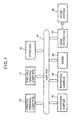
- FIG. 1 is a block diagram illustrating the configuration of a LAN network practiced as one embodiment of the invention, the LAN network being preferably for use in music performance.
- a LAN bus 10 is connected to music performance apparatuses such as a desktop personal computer 12, a note-type portable personal computer 14, a music keyboard 16, a waveform samplers 18, 20, a mixer 22, and a tone generator 24.
- the LAN bus 10 is compliant with the IEEE 1394 standard for example. It may also be a bus compliant with other high-speed interface standards such as the USB standard.
- the personal computers 12, 14 each have sequencer software and performance data for plural pieces of music, and provide capabilities of editing desired performance data on the basis of the sequences software and executing automatic performance on the basis of predetermined performance data.
- the keyboard 16 has keys for music performance and outputs performance data in accordance with key operations executed on the keyboard.
- the waveform samplers 18, 20 each sample an analog audio signal (a voice signal) inputted from an input device such as a microphone or a recorder to generate sample data (waveform data) representing an amplitude value for each sample obtained, thereby outputting the generated sample data.
- the frequency of a sampling clock used is 48 KHz for example; it may be 44.1 KHz or selectable between 48 KHz and 44.1 KHz.
- the mixer 22 mixes the sample data (the waveform data), thereby outputting the mixed sample data.
- the tone generator 24 has plural sounding channels (16 for example) and can specify multi-level pitches (128 for example) for each sounding channel.
- the tone generator can assign many timbres (100 to 1000 for example) to each sounding channel and sound music tones on the basis of externally supplied waveform data.
- the sound system 26 includes a power amplifier for right and left channels and a speaker, and converts a tone signal supplied from the tone generator 24 into acoustic sound.
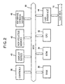
- FIG. 2 is a block diagram illustrating the configuration of the desktop personal computer 12 shown in FIG. 1 .
- the desktop personal computer 12 may work as a communication control apparatus according to the invention.
- a bus 30 is connected to a CPU (Central Processing Unit) 32, a ROM (Read Only Memory) 34, a RAM (Random Access Memory) 36, a controls group 38, a display device 40, a non-volatile memory 42, a LAN interface 44, and an external storage device 46.
- CPU Central Processing Unit
- ROM Read Only Memory
- RAM Random Access Memory
- the CPU 32 executes various processing operations as instructed by programs stored in the ROM 34.
- the programs may be provided by a machine readable medium such as an magnetic or optical disk loaded into the external storage device 46.
- the RAM 36 includes a storage area for use as registers, which hold data resulted from the processing executed by the CPU 32.
- the controls group 38 includes a keyboard having numeric and character keys for example and also includes a mouse as a pointing device.
- the display device 40 can display various pieces of information on a display screen and a cursor, which is operated by the mouse of the controls group 38.
- the non-volatile memory 42 can retain stored information after the power supply is turned off. As shown in FIG. 4 , this memory includes various memory blocks, which will be described later.
- the LAN interface 44 is compliant with the IEEE 1394 standard for example. Interfaces compliant with high-speed interface standards such as USB may also be used.
- the external storage device 46 includes a recording medium such as a magnetic or optical disk, which stores performance data for many pieces of music.
- the performance data for a desired piece of music can be read from the external storage device 46 into the RAM 36 by operating the controls group 38.
- the performance data read in the RAM 36 are displayed on the display device 40 to be edited as desired by operating the controls group 38.
- note-on information a sounding command and pitch specification information
- note-off information a muting command and pitch specification information included in the performance data in the RAM 36 may be transmitted to the tone generator 24 through the LAN interface 44 and the LAN bus 10 by taking synchronization on the basis of synchronization information to be described later, thereby executing automatic performance of music.
- the configuration described above is that of the personal computer 12.
- the other personal computer 14 has generally the same configuration except for the external storage device 46.
- the personal computer 14 can share the performance data stored in the external storage device 46 with the personal computer 12 to execute the same performance data edit processing and music automatic performance for example as the personal computer 12.
- the music keyboard 16 has a configuration equivalent to that shown in FIG. 2 except that a music performance keyboard unit is provided instead of the external storage device 46.
- the keyboard 16 allows the user to manually play music by transmitting information such as note-on and note-off information to the tone generator 24 through the LAN interface 44 and the LAN bus 10 of the network.
- the waveform samplers 18 and 20 each have a configuration equivalent to that shown in FIG. 2 except that a sampling A/D (Analog/Digital) converter is provided instead of the external storage device.
- the user can generate tones based on sample data by transmitting the sample data from the A/D converter of the waveform sampler 18 or 20 to the tone generator 24 through the LAN interface 44 and the LAN bus 10 of the network.
- the mixer 22 has a configuration equivalent to that shown in FIG. 2 except that a DSP (Digital Signal Processor) device is provided instead of the external storage device 46.
- the mixer 22 can mix the sample data supplied from the waveform samplers 18 and 20 for example.
- the user can generate tones based on mixed sample data by transmitting the mixed sample data from the mixer 22 to the tone generator 24 through the LAN interface 44 and the LAN bus 10 of the network.
- DSP Digital Signal Processor
- the tone generator 24 has a configuration equivalent to that shown in FIG. 2 except that a tone generating unit is provided instead of the external storage unit 46.
- the tone generating unit has 16 sounding channels for example, each of which is assigned with performance information such as timbre, note-on, and note-off by the CPU 32 of the user's apparatus selected from node apparatuses involved in the network, thereby generating tone signals.
- An audio output terminal of the tone generating unit is connected to the sound system 26 from which tone signals are sounded.
- the ROM 34 of the user's apparatus which is one of the node apparatuses, or the ROM in the LAN interface 44 of the user's apparatus stores communication control software (LAN management software).
- the CPU 32 of the user's apparatus determines flows of music data and synchronization information among plural node apparatuses as instructed by the communication control software in accordance with the operation executed on the controls group 38 of the user's apparatus.
- the user's apparatus selected from among the node apparatuses 12 through 24 serves as the inventive communication control apparatus.
- FIG. 3 is a block diagram illustrating an example of the data and synchronization information flows thus determined.
- FIG. 3 shows the flows of data and a clock signal (synchronization information) among plural music performance apparatuses connected to the LAN network illustrated in FIGS. 1 and 2 .
- performance data PD 1 such as note-on/off from the personal computer 12
- performance data PD 2 such as note-on/off from the personal computer 14
- performance data PD 3 such as note-on/off from the keyboard 16 are supplied to the tone generator 24.
- Sample data SDAT 1 from the waveform sampler 18 and sample data SDAT 2 from the waveform sampler 20 are supplied to the mixer 22, the mixed sample data MDAT being supplied to the tone generator 24.
- a clock signal CL is supplied from the personal computer 12 to the personal computer 14, the keyboard 16, the waveform samplers 18 and 20, the mixer 22, and the tone generator 24.
- the tone generator 24 can generate a tone signal based on the mixed sample data MDAT in synchronization with the clock signal CL as instructed by any of the data PD 1 through PD 3 , thereby permitting synchronous performance by use of the sample data.
- the present invention relates to a technology of setting the transmission/reception (master/slave) of synchronization information (the clock signal CL).
- This setting technology forms a part of the above-mentioned communication control software and will be described later with reference to FIGS. 4 through 13 .
- FIG. 3 indicates that the flow of the clock signal CL is set independently of the flow of data.
- FIG. 4 is a diagram illustrating various memory blocks provided in the non-volatile memory 42 of each node apparatus.
- Memory blocks CCP, CST, FCP, FST, and CMS can store synchronization capability information, synchronization status information, Fs management capability information, Fs management status information, and common master information, respectively.
- Fs herein denotes sampling clock frequency.
- the music performance apparatuses 12 through 24 are referred to nodes for the purpose of description.
- Synchronization capability information indicates presence or absence of a master capability (transmission capability) and/or a slave capability (receive capability) for each Fs.
- the master capability herein denotes a capability of transmitting a clock signal by a node concerned itself without being supplied with a clock signal from another node.
- the synchronization capability information stored in the memory block CCP cannot be changed in principle. However, it may be changed when the user changes settings inside the node main.
- the synchronization status information indicates whether the node is master or slave along with Fs. When this information indicates that the node is slave, it also indicates which node is master. In this case, the synchronization status information can indicate one of the master and slave states which are represented by the synchronization capability information of the same node as having the capability. Namely, the synchronization status information cannot represent the master or slave state which is represented by the synchronization capability information of the same node as having no capability.
- the synchronization status information stored in the memory block CST may be changed by another node or when the user changes settings inside the node main.
- the Fs management capability information represents selection among three of master/slave settings for Fs specifications as shown in FIG. 6 .
- Fs auto an Fs value is automatically selected depending on a situation.
- auto mode the transmission/reception of synchronization information is automatically determined on the basis of synchronization status information or synchronization capability information.
- the professional mode the reception of synchronization information is automatically determined on the basis of common master information.
- the manual mode the user specifies the transmission/reception of synchronization information with reference to the transmission/reception capability indicated on the basis of synchronization capability information.
- the auto mode is for general users not well familiar with digital audio technology, while the professional mode and the manual mode are for users versed in digital audio.
- the Fs management capability information stored in the memory block FCP cannot be changed in principle, but may be changed when the user changes the internal settings of the node main.
- an appropriate Fs value is automatically selected by specifying "Fs auto" without specifying any Fs value.
- the professional mode is selected, only the Fs value with 44.1 KHz or 48 KHz specified can be used.
- the Fs management status information represents any of the modes and Fs values that is made selectable by the Fs management capability information.
- the Fs management status information stored in the memory block FST may be changed by another node. It should be noted that there should be no contradiction between the above-mentioned synchronization capability information, synchronization status information, Fs management capability information, and Fs management status information.
- Fs 48 KHz.
- the auto mode of Fs auto or the professional mode of 44.1 KHz may be selected.
- the manual mode cannot be selected for any of the three Fs specifications.
- the common master information specifies a transmission node (a common master) of synchronization information common to the network for each Fs.
- Use of the common master information allows the automatic determination of the reception (slave) of synchronization information in the professional mode and, at the same time, omission of the inclusion of the information indicative of a node which is master into the synchronization status information.
- Common master setting is executed by an explicit operation of the user. If a common master already exists, its Fs can be changed by an explicit operation by the user. If this is done, the node which has been common master so far is no common master any more. The user can cancel the common master by specifying the corresponding node.
- the user changes the Fs of a common master, that node is no more the common master of the original Fs. For example, if the Fs of a common master is changed from 48 KHz to 44.1 KHz, that node is no more the common master of 48 KHz. Thereafter, another node of 44.1 KHz may be made a common master automatically or by the discretion of the user.
- FIGS. 7 and 8 are flowcharts describing master/slave setting process. This process is executed in any of the nodes.
- the node shown in FIG. 2 is exemplified as the communication control apparatus.
- the other nodes may serve as the communication control apparatus in the same manner.
- the process shown in FIGS. 7 and 8 is started when the power switch is turned on with the node shown in FIG. 2 connected to the LAN bus 10.
- step 50 the registers are initialized.
- the Fs management status information stored in the memory block FST indicates the auto mode
- the synchronization status information stored in the memory block CST is cleared. This is because, for the auto mode, new master/slave setting must be executed regardless of the previous master/slave setting.
- the synchronization status information in the memory block CST and the common master information in the memory block CMS are not cleared, so that the previous master/slave setting is maintained.
- the synchronization status information in the memory block CST is not cleared, so that the previous master/slave setting is reproduced.
- step 52 it is determined whether a new node is connected with the LAN bus 10 or an old node is disconnected from the LAN bus 10. If the decision is yes, then the same initialization processing as that of step 50 is executed in step 54. The same initialization processing as that executed at the power-on sequence is executed because the system configuration changes at the time of connection and disconnection of a node.
- step 56 the common master information in the memory block CMS is displayed on the display device of the communication control apparatus for each node and the nodes having master capability are indicated with reference to the synchronization capability information in the memory block CCP of each node.
- the common master information may not be displayed because there is no node having master capability. Display of the nodes having master capability is made on the display screen of the display device 40. Various display operations to be described later are also made on the display device 40.
- step 58 it is determined whether the common master has been specified from the controls group 38. Because the information in the memory block CMS of each node was collected and displayed in step 56, the user can determine whether to specify (and change) the common master after confirming the presence or absence of the common master. Because the node having master capability is displayed on the basis of the information stored in the memory block CCP of each node in step 56, the user can specify a desired node as the common master by referring to the display. The specification can be made by use of the corresponding keys and/or the mouse of the controls group 38. This holds true with various operations such as specification, selection, and indication to be described later.
- step 60 the common master information (indicative of common master and Fs) is written to the memory block CMS of the user's node or another node according to the specification, displaying this common master information for the corresponding node. If the previous common master information is found in the memory block CMS, it is overwritten by the new information.
- step 62 the Fs management capability information in the memory block FCP is displayed for each node and, at the same time, the node name and the Fs specification are displayed by referring to the Fs management status information in the memory block FST for each node.
- the Fs management status information may not be displayed because of its absence.
- step 64 it is determined whether the mode name or the Fs has been specified from the controls group 38. Because the information stored in the memory blocks FCP and FST of each node is displayed in step 62, the user can specify (and change) the mode and the Fs of the user's node or other node by referring to the displayed information.
- step 64 If the decision of step 64 is yes, then, in step 66, the Fs management status information (mode name and Fs specification) is written to the memory block FST of the user's node or other node according to the specification, thereby displaying this Fs management status information for the corresponding node. If the previous Fs management status information is found in the memory block FST, it is overwritten by the new information.
- mode name and Fs specification the Fs management status information
- step 68 it is determined the mode in which the user's node is placed. If the decision is the manual mode (MUN), then, in step 70, the manual mode processing is executed as will be described with reference to FIG. 9 . If the decision in step 68 is the professional mode (PRO), then, in step 72, the professional mode processing is executed as will be described with reference to FIG. 10 . Further, if the decision in step 68 is the auto mode (AUT), then, in step 74, the auto mode processing is executed as will be described with reference to FIG. 11 .
- MUN manual mode
- PRO professional mode
- step 72 the professional mode processing is executed as will be described with reference to FIG. 10 .
- step 74 the auto mode processing is executed as will be described with reference to FIG. 11 .
- step 76 it is determined whether the end of master/slave setting process has been instructed from the controls group 38. If the decision if no, then, back to step 52, the above-mentioned processing is repeated. If the decision is yes, the master/slave setting process comes to an end.
- FIG. 9 is a flowchart describing the manual mode processing.
- step 80 synchronization capability information is acquired from the memory blocks CCPs of the user's node and other nodes and the acquired information is stored in the storage device and displayed on the display device. The user can specify the master or slave for a desired node by referring to the displayed information.
- step 82 it is determined whether master specification has been made from the controls group 38. If the decision is yes, then, in step 84, the synchronization status information (indicative of the master and Fs) is written to the memory block CST of the master node according to the specification, displaying this synchronization status information. If the previous synchronization status information is found in the memory block CST of the master node associated with the specification, it is overwritten with the new information.
- step 86 it is determined whether slave specification has been made from the controls group 38. If this decision is yes, then, in step 88, the synchronization status information (indicative of the slave, the associated master node, and the Fs) is registered to the memory block CST of the slave node according to the specification, displaying this synchronization status information. If the previous synchronization status information is found in the memory block CST of the slave node associated with the specification, it is overwritten with the new information.
- step 90 it is determined whether there is a mismatch in Fs between master node and slave node. If the decision is yes, then, in step 92, a message is displayed telling that synchronization is disabled due to Fs mismatch. If the decision is no or the processing of step 92 has come to an end, the routine shown in FIGS. 7 and 8 is resumed.
- step 94 it is determined whether the clearing of the manual mode has been instructed from the controls group 38. If this decision is no, then, back to step 82, the operation for master specification is waited for. If the decision of step 94 is turned yes, then, in step 96, the Fs management status information (indicative of the manual mode and the Fs) is erased from the memory block FST of the user's node and the corresponding display is also turned off.
- step 98 it is determined whether the clearing of the manual mode has been specified from the controls group 38. If this decision is no, then, back to step 86, the operation for slave specification is waited for. If the decision in step 98 is turned yes, then, in step 96, the Fs management status information is erased from the memory block FST of the user's node and the corresponding display is also turned off. Then, the routine shown in FIGS. 7 and 8 is resumed.
- the communication control apparatus is provided in the form of the personal computer 12 or else for setting a plurality of node apparatuses 12 through 24 involved in a network 10 to either of a transmitter and a receiver of synchronization information circulated through the network to synchronize the node apparatuses with each other.
- a storage device such as RAM 36 memorizes capability information representing either of an active capability to transmit the synchronization information and a passive capability to receive the synchronization information, owned by each of the node apparatuses 12 through 24.
- An indicating device such as the display device 40 indicates the active capabilities and the passive capabilities owned by the node apparatuses 12 through 24 involved in the network according to the memorized capability information.
- a specifying device such as the controls group 38 is operated in association with the indicated active capabilities and the passive capabilities of the node apparatuses for outputting status information effective to specify each node apparatus to a transmitter or a receiver of the synchronization information.
- a plurality of memory blocks are provided in correspondence to the plurality of the node apparatuses 12 through 24 in the form of non-volatile memory 42 to memorize status information of the corresponding node apparatuses 12 through 24.
- a registering device implemented by the CPU 32 registers each of the outputted status information into each memory block to set the corresponding node apparatus to a transmitter of the synchronization information when the status information specifies the transmitter, and to set the corresponding node apparatus to a receiver of the synchronization information when the status information specifies the receiver.
- the plurality of the node apparatuses 12 through 24 can transfer data through the network at one of multiple sampling frequencies based on the synchronization information, such that the storage device stores a multiple of the capability information in correspondence to the multiple sampling frequencies, and such that each memory block stores a multiple of the status information corresponding to the multiple sampling frequencies.
- the plurality of the node apparatuses 12 through 24 are connected to each other through a local area network 10.
- the plurality of the node apparatuses 12 through 24 transact music data representing a music piece with each other in response to the synchronization information through the local area network to constitute a music system for generating the music piece.
- FIG. 10 is a flowchart describing the professional mode.
- step 100 information is acquired from the memory blocks CMSs of the user's node and other nodes. Then, in step 102, it is determined whether the common master information is included in the acquired information.
- step 104 all common master information is displayed.
- step 106 it is determined whether there are plural pieces of common master information. If this decision is yes, then, in step 108, one piece of common master information is selected according to the instruction by the user, and the selected piece of common master information is displayed. At this time, the user can instruct the selection by referring to the information displayed in step 104.
- the common master information may also be automatically selected without the user instruction.
- step 110 it is determined whether the common master corresponding to this one piece of common master information is a node other than the user's node. If the decision is no, it indicates that the user's node is the common master and therefore the processing of step 112 is not required, so that the routine of FIGs. 7 and 8 is resumed.
- step 112 the synchronization status information is written to the memory block CST of the user's node with the user's node being as the slave of the common master.
- the synchronization status information may be the Fs indicative of the slave and may not include the information indicative of the common master.
- step 114 it is determined whether there is a mismatch in Fs between master and slave. If the decision is yes, then, in step 116, a message is displayed telling that the Fs mismatch is found and therefore synchronization is disabled.
- step 118 a message is displayed telling that there is no common master and therefore synchronization is disabled. Then, the routine shown in FIGS. 7 and 8 is resumed.
- the inventive communication control apparatus is provided for setting a plurality of node apparatuses involved in a network to either of a transmitter and a receiver of synchronization information circulated through the network to synchronize the node apparatuses with each other.
- a storage device memorizes capability information representing either of an active capability to transmit the synchronization information and a passive capability to receive the synchronization information, possessed by each of the node apparatuses.
- An indicating device indicates node apparatuses possessing the active capabilities according to the memorized capability information.
- a specifying device outputs common master information effective to specify one node apparatus among the indicated node apparatuses to a transmitter of synchronization information commonly used throughout the network.
- a first memory block memorizes the common master information outputted from the specifying device.
- a determining device implemented by the CPU 32 operates based on the memorized common master information for outputting status information effective to determine another node apparatus among the plurality of the node apparatuses to a receiver of the synchronization information transmitted from said one node apparatus.
- a second memory block is provided in correspondence to said another node apparatus to memorize status information of said another node apparatus.
- a registering device registers the outputted status information into the second memory block to set said another node apparatus to a receiver of the synchronization information.
- FIG. 11 is a flowchart describing the auto mode processing.
- step 120 information is acquired from the memory blocks CMSs of the user's node and other nodes as with step 100 described above.
- step 122 it is determined whether the common master information is included in the acquired information as with step 102 described above.
- step 122 If the decision in step 122 is yes (namely, the common master information is found), the processing of steps 104 through 116 is executed.
- the processing of steps 104 through 116 is the same as that of steps 104 through 116 described above with respect to the professional mode shown in FIG. 10 , so that the description of this processing will be skipped.
- step 112 If the decision in step 112 is no (namely, no common master information is found), then, in step 124, synchronization status information is acquired from the memory block CST of the nodes of other parties in data communication, or synchronization capability information is acquired from the memory blocks CCPs of the user's node and the nodes of the other parties.
- step 126 master/slave decision processing is executed on the basis of the acquired information. If the synchronization status information has been acquired from the memory block CST, the master/slave decision processing is executed as will be described with reference to FIG. 12 . If the synchronization capability information has been acquired from the memory blocks CCPs, the master/slave decision processing is executed as will be described with reference to FIG. 13 . In each processing shown in FIGS. 12 and 13 , master/slave decision may not be executed under some conditions.
- step 1208 it is determined whether master/slave decision has been made. In the processing shown in FIG. 12 , it is determined whether master or slave has been determined for the user's node. In the processing shown in FIG. 13 , it is determined whether master or slave has been determined for both the user's node and other nodes.
- step 130 the synchronization status information is written to the memory block CST according to the decision and this synchronization status information is displayed.
- the synchronization status information is written to the memory block CST of the user's node.
- the synchronization status information is written to the memory blocks CSTs of the user's node and the other node.
- step 132 a message is displayed telling that master/slave is not determined and therefore synchronization is disabled. Then, the routine shown in FIGS. 7 and 8 is resumed.
- the inventive communication control apparatus is provided for setting a plurality of node apparatuses including a first node apparatus and a second node apparatus involved in a network to either of a transmitter and a receiver of synchronization information circulated through the network to synchronize the node apparatuses with each other.
- a storage device memorizes common master information effective to specify the first node apparatus to a transmitter of synchronization information commonly used throughout the network.
- a determining device operates based on the memorized common master information for outputting status information effective to determine the second node apparatus to a receiver of the synchronization information transmitted from the first node apparatus.
- a memory block is provided in correspondence to the second node apparatus to memorize status information of the second node apparatus.
- a registering device registers the outputted status information into the memory block to set the second node apparatus to a receiver of the synchronization information.
- FIGS. 12A and 12B illustrate an example of the master/slave determination.
- the master/slave determination is automatically executed according to a first rule that the existing setting is not changed and a second rule that the determination is made by following the synchronization status information of the node of the other party in data communication.
- node A sends an audio stream (for example, waveform data) AST 1 and, at the same time, clock stream WST 1 to node B and node A is the clock master of node B.
- the master/slave determination of node C is executed as follows when setting the transmission of audio stream AST 2 from node C in the auto mode to node B.
- the master/slave relationship is left unchanged between node A and node B. Then, the synchronization status information of node B, the communication mate of node C, is referenced. If this reference indicates that the synchronization status information indicates the reception (slave) of the clock signal from node A (master), master/slave is determined for node C such that clock stream WST 2 is received not from node B but from node A. Namely, the synchronization status information of node C indicates the slave state with node A being the master.
- the communication control apparatus is provided for setting a plurality of node apparatuses including a first node apparatus B, a second node apparatus A and a third node apparatus C involved in a network to either of a transmitter and a receiver of synchronization information circulated through the network to synchronize the node apparatuses with each other.
- a memory block memorizes status information effective to specify the first node apparatus B to a receiver of the synchronization information transmitted from the second node apparatus A.
- a determining device operates based on the memorized status information for outputting status information effective to determine the third node apparatus C to a receiver of the synchronization information transmitted from the second node apparatus A.
- Another memory block is provided in correspondence to the third node apparatus C to memorize status information of the third node apparatus C.
- a registering device registers the outputted status information into said another memory block to set the third node apparatus C to a receiver of the synchronization information.
- the synchronization status information associated with the reference indicates the transmission (master) from node B
- the reception of the clock signal from node B is determined for node C and the synchronization status information of node C indicates the slave state with node B being the master.
- the inventive communication control apparatus is provided for setting a plurality of node apparatuses including a first node apparatus B and a second node apparatus C involved in a network to either of a transmitter and a receiver of synchronization information circulated through the network to synchronize the node apparatuses with each other.
- a memory block memorizes active status information effective to specify the first node apparatus B to a transmitter of synchronization information.
- a determining device operates based on the memorized active status information for outputting passive status information effective to determine the second node apparatus C to a receiver of the synchronization information transmitted from the first node apparatus B.
- Another memory block is provided in correspondence to the second node apparatus C to memorize status information of the second node apparatus C.
- a registering device registers the outputted passive status information into said another memory block to set the second node apparatus C to a receiver of the synchronization information.
- the master node may be changed depending on the node connection sequence even if the combination of connected nodes is the same.
- the manual mode or the professional mode may be selected.
- FIG. 13 is a diagram illustrating another example of master/slave determination.
- the master/slave determination is made by following the above-mentioned first rule and a third rule that the determination is made by following the synchronization capability information of the user's node and the node of the other party (counter party node) in data communication.
- One of the user's node and the counter party node becomes the data transmission side, and the other becomes the data reception side.
- Classification of the contents of the synchronization capability information of both sides is summarized as (A) “capable of becoming only the master", (B) “capable of becoming master or slave", and (c) “capable of becoming only the slave” as shown in “Transmission side conditions” shown in FIG. 13 for the transmission side.
- the reception side is also one of the above-mentioned conditions (A) through (c) as shown in "Reception side conditions” shown in FIG. 13 .
- Combining the three conditions on the transmission side and the three conditions on the reception side results in combinations S 1 through S 9 . Of these combinations, S 1 and S 9 cannot determine master/slave, while S 2 through S 8 can determine master/slave.
- step 126 shown in FIG. 11 a comparison is made between the synchronization capability information of the data transmission node and the data reception node to determine which of S 1 through S 9 is applied.
- master/slave is determined. For example, if the determination is S 5 , the data reception node is made master and the data transmission node is made slave. At this time, the synchronization status information of the data reception node indicates the master state while the synchronization status information of the data transmission node indicates the slave state with the data reception node being the master. It should be noted that, if the determination is S 1 or S 9 , the user is alarmed in step 132.
- the inventive communication control apparatus is constructed for setting a plurality of node apparatuses including a first node apparatus and a second node apparatus involved in a network to either of a transmitter and a receiver of synchronization information circulated through the network to synchronize the node apparatuses with each other.
- a storage device memorizes capability information representing either of an active capability to transmit the synchronization information and a passive capability to receive the synchronization information, owned by each of the first node apparatus and the second node apparatus.
- a determining device is operated according to the predetermined rule shown in FIG.
- First and second memory blocks are provided in correspondence to the first and second node apparatuses to memorize status information of the corresponding node apparatuses.
- a registering device registers the status information into the first memory block to set the first node apparatus to a transmitter or a receiver of the synchronization information when the status information is determined for the first node apparatus, and registers the status information into the second memory block to set the second node apparatus to a transmitter or a receiver of the synchronization information when the status information is determined for the second node apparatus.
- the node in the auto mode may be connected to the node of another mode (manual mode or professional mode).
- the first rule is applied by assuming that the master/slave setting has already been made for the node of another mode. Namely, the master/slave setting for the node in the auto mode is executed with the master/slave setting for the node in another mode unchanged.
- an alternative may be proposed that the auto mode and the professional mode be combined into one mode. Namely, if a common master exists on the bus, it is made the master; if no common master exists on the bus, the master is determined automatically.
- this scheme has a problem that follows.
- a certain node is slave to the common master. If the common master disappears from the bus, it is preferable, from the viewpoint of professional use, to alarm the user that there is no common master on the bus. Namely, it is not preferable to automatically determine another master. On the other hand, if the slave node is removed from the bus and is connected to another bus for which no master is determined, it is preferable, from the viewpoint of consumer use, to automatically determine the master. In any case, it only appears to the nodes that there is no master any more and therefore they cannot make distinction between the masters.
- the embodiment of the invention arranges the professional mode and the auto mode separately.
- the user can specify the profession mode.
- the user can specify the auto mode. If there is no common master in the professional mode, the user is alarmed in step 118. If there is no common master in the auto mode, master/slave is automatically determined in steps 124 and 126.
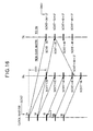
- Each WC packet WCPK includes synchronization offset information SYO and sample count information SCNT.
- the synchronization offset information SYO represents a count value equivalent to a transfer delay time (325 ⁇ sec) as shown in FIG. 16 .
- Each WC packet WCPK is received through a LAN interface 44T at a data transmission node Tx shown in FIG. 14 (node C shown in FIG. 12 for example) and a LAN interface 44R at a data reception node Rx shown in FIG. 15 (node B shown in FIG. 12 for example).
- SCNT 24, 32, 40, and so on along vertical lines Tx and Rx represent sample count timings at the data transmission node Tx and the data reception node Rx, respectively.
- the data transmission node Tx sends a data packet DPK to the data reception node Rx at each of the sample count timings 24, 32, 40, and so on.
- Each data packet DPK includes sample count information SCNT and sample data SDAT for four samples.
- a sum total of the synchronization offset information SYO and the sample count information SCNT included in the WC packet WCPK is inputted in a FIFO (Fist In, First Out memory) 140 and the sample count information SCNT included in the WC packet WCPK is inputted in a FIFO 142.
- a comparator 144 compares time information ITM from a timer for counting a high-speed clock signal in the node Tx with the sum total supplied from the FIFO 140 and, when a match is found, output a match signal to trigger a PLL (Phase Locked Loop) circuit 146.
- PLL Phase Locked Loop
- the PLL circuit 146 generates a clock pulse in timed relations corresponding to 24, 32, 40, and so on indicated along the vertical line Tx shown in FIG. 16 , the generated timing pulse being supplied to the node Tx as a sampling clock signal SCK.
- an AND gate 148 supplies the sample count information SCNT supplied from the FIFO 140 to the node Tx and an adder 150.
- the adder 150 adds sample offset information SMO to the sample count information SCNT, the sample offset information being 17 for example (refer to FIG. 16 ). Consequently, sample offset 17 is added to sample count 32 for example, sample count information SCNT representing 32 + 17 being inputted from the adder 150 into a FIFO 152.
- Sample data SDAT for four samples corresponding to sample count timing 32 are inputted in a FIFO 154 from the node Tx.
- the sample count information SCNT in the FIFO 152 and the sample data SDAT in the FIFO 154 constitute a data packet DPK, which is sent to the node Rx in a timed relation of sample count 32 (refer to FIG. 16 ).
- the sum total of the synchronization offset information SYO and the sample count information SCNT included in the WC packet WCPK supplied from the clock master is inputted in a FIFO 160.
- a comparator 162 compares time information from the timer for counting the high-speed clock signal in the node Rx with the sum total value from the FIFO 160 and, when a match is found, outputs a match signal to trigger a PLL circuit 164. Consequently, the PLL circuit 164 generates a clock pulse in timed relations corresponding to 24, 32, 40 and so on along the vertical line Rx shown in FIG. 16 , the generated clock pulse being supplied to the node Rx as a sampling clock signal SCK.
- the data pack DPK including the sample count information SCNT of sample count (32 + 17) and the sample data SDAT arrives at the interface 44R.
- the sample count information SCNT and the sample data SDAT are inputted in the a FIFO 166 and a FIFO 168 respectively.
- a comparator 170 compares the sample count information SCNT with time information ITM from the timer in the node Rx and, when a match is found, supplies a match signal to an AND gate 172. Consequently, the sample data SDAT in the FIFO 168 are supplied to a FIFO 174 through the AND gate 172.
- the manual specification by the user for transmission/reception is facilitated by indicating the transmission capability or the reception capability for each node apparatus connected to a network on the basis of synchronization capability information, the reception of synchronization information is automatically determined on the basis of common master information, the reception of synchronization information is automatically determined on the basis of synchronization status information, and the transmission/reception of synchronization information is automatically determined on the basis of synchronization capability information. Consequently, the transmission/reception of synchronization information can be set appropriately and simply.
Landscapes
- Engineering & Computer Science (AREA)
- Signal Processing (AREA)
- Computer Networks & Wireless Communication (AREA)
- Computer Security & Cryptography (AREA)
- Telephonic Communication Services (AREA)
- Small-Scale Networks (AREA)
- Electrophonic Musical Instruments (AREA)
- Communication Control (AREA)
- Data Exchanges In Wide-Area Networks (AREA)
Abstract
Description
- The present invention relates generally to a communication control apparatus preferably for use in a network such as a LAN (Local Area Network). More particularly, the present invention relates to a communication control apparatus that stores, for each of node apparatuses connected to the network, information representative of synchronization signal transmission and reception capabilities and synchronization signal transmission/reception setting status, and sets master and slaves of the synchronization signal appropriately and simply with reference to pieces of the stored information.
- Systems for connecting plural music performance apparatuses (such as a synthesizer, a rhythm machine, a sequencer, and a computer) for synchronous performance are known in which MIDI (Musical Instrument Digital Interface) compliant apparatuses are interconnected by a MIDI cable to transmit a MIDI clock consisting of an 8-bit message of hexadecimal "FB" from one MIDI apparatus on the data transmission side to another MIDI apparatus on the data reception side, thereby performing music while taking synchronization based on this synchronization signal.
- However, the above-mentioned prior-art MIDI performance systems have a data transfer rate as low as 31.25 Kpbs, being incapable of constructing a system in which music is performed while transmitting sample data by use of a sampler having a sampling clock of 44.1 KHz.
- A music performance system capable of providing high-speed data transfer may be constructed by use of a high-speed interface (having data transfer rates up to 10 through 50 Mbps) such as USB (Universal Serial Bus) or IEEE 1394. Currently, however, no sufficient researches have been carried out into the setting of master/slave for the synchronization information transmission/reception in such high-speed networks. As with the conventional MIDI scheme, it could be possible to adopt a scheme in which the synchronization information is always transmitted from an upstream of data to a downstream. However, such a rigid scheme causes the flow of the synchronization information to be restricted by the flow of music data, thereby making it impossible to provide proper settings of the master and slaves. It is also difficult with such a rigid scheme for users to execute master/slave setting by referring to instruction manuals and like.
- It is therefore an object of the present invention to provide a novel communication control apparatus, which permits the proper and simple setting of transmission/reception nodes (master/slaves) of synchronization information in a high-speed network.
- In carrying out the invention and according to one aspect thereof, there is provided a first communication control apparatus for setting a plurality of node apparatuses involved in a network to either of a transmitter and a receiver of synchronization information circulated through the network to synchronize the node apparatuses with each other. In the communication control apparatus, a storage device memorizes capability information representing either of an active capability to transmit the synchronization information and a passive capability to receive the synchronization information, owned by each of the node apparatuses. An indicating device indicates the active capabilities and the passive capabilities owned by the node apparatuses involved in the network according to the memorized capability information. A specifying device is operated in association with the indicated active capabilities and the passive capabilities of the node apparatuses for outputting status information effective to specify each node apparatus to a transmitter or a receiver of the synchronization information. A plurality of memory blocks are provided in correspondence to the plurality of the node apparatuses to memorize status information of the corresponding node apparatuses. A registering device registers each of the outputted status information into each memory block to set the corresponding node apparatus to a transmitter of the synchronization information when the status information specifies the transmitter, and to set the corresponding node apparatus to a receiver of the synchronization information when the status information specifies the receiver.
- According to the first communication apparatus, the indicating device indicates the capability of transmission or reception on the basis of the synchronization capability information stored in the storage device for each of the plurality of node apparatuses. The user refers to the indication made by the indicating device and specifies the transmission or the reception of synchronization information for each node apparatus through the specifying device. Synchronization status information indicative of the transmission of synchronization information is written to the memory block corresponding to the node apparatus for which the transmission of synchronization information has been specified. Synchronization status information indicative of the reception of synchronization information is written to the memory block corresponding to the node apparatus for which the reception of synchronization information has been specified. Consequently, the user can simply and surely specify the transmission/reception of synchronization information for each node according to the indication made by the indicating device, thereby providing the transmission/reception setting as specified by the user.
- In carrying out the invention and according to another aspect thereof, there is provided a second communication control apparatus for setting a plurality of node apparatuses including a first node apparatus and a second node apparatus involved in a network to either of a transmitter and a receiver of synchronization information circulated through the network to synchronize the node apparatuses with each other. In the communication control apparatus, a storage device memorizes common master information effective to specify the first node apparatus to a transmitter of synchronization information commonly used throughout the network. A determining device operates based on the memorized common master information for outputting status information effective to determine the second node apparatus to a receiver of the synchronization information transmitted from the first node apparatus. A memory block is provided in correspondence to the second node apparatus to memorize status information of the second node apparatus. A registering device registers the outputted status information into the memory block to set the second node apparatus to a receiver of the synchronization information.
- According to the second communication control apparatus, the storage device stores the common master information for specifying the first node apparatus as a transmitter of synchronization information common to the network. The determining device determines, for the second node apparatus, the reception of synchronization information from the first node apparatus on the basis of the common master information stored in the storage device. Synchronization status information indicative of the reception of synchronization signal is written to the memory block according to the determination made by the determining device. Consequently, the reception of synchronization information can be automatically determined on the basis of the common master information, allowing the setting of reception in accordance with the automatic determination.
- In carrying out the invention and according to still another aspect thereof, there is provided a third communication control apparatus for setting a plurality of node apparatuses involved in a network to either of a transmitter and a receiver of synchronization information circulated through the network to synchronize the node apparatuses with each other. In the communication control apparatus, a storage device memorizes capability information representing either of an active capability to transmit the synchronization information and a passive capability to receive the synchronization information, possessed by each of the node apparatuses. An indicating device indicates node apparatuses possessing the active capabilities according to the memorized capability information. A specifying device outputs common master information effective to specify one node apparatus among the indicated node apparatuses to a transmitter of synchronization information commonly used throughout the network. A first memory block memorizes the common master information outputted from the specifying device. A determining device operates based on the memorized common master information for outputting status information effective to determine another node apparatus among the plurality of the node apparatuses to a receiver of the synchronization information transmitted from said one node apparatus. A second memory block is provided in correspondence to said another node apparatus to memorize status information of said another node apparatus. A registering device registers the outputted status information into the second memory block to set said another node apparatus to a receiver of the synchronization information.
- According to the third communication control apparatus, a node apparatus capable of transmission is indicated by the indicating device on the basis of synchronization capability information stored in the storage device. The user refers to the indication made by the indicating device to specify through the specifying device one node apparatus as a transmitter (a common master) of synchronization information common to the network. The common master information indicative of one node apparatus associated with the specification is stored in the first memory block. The determining device determines, for another node apparatus associated with the specification, the reception of synchronization information from one node apparatus associated with the specification on the basis of the common master information stored in the first memory block. Synchronization status information indicative of the reception of synchronization information is written to the second memory block according to the determination made by the determining device. Consequently, the user can simply specify a desired node apparatus as the common master according to the indication made by the indicating device, thereby the determining device automatically determining the reception of synchronization information in another node apparatus with respect to the specified common master. This permits the setting of transmission/reception in accordance with user specification and automatic determination.
- In carrying out the invention and according to yet another aspect thereof, there is provided a fourth communication control apparatus for setting a plurality of node apparatuses including a first node apparatus, a second node apparatus and a third node apparatus involved in a network to either of a transmitter and a receiver of synchronization information circulated through the network to synchronize the node apparatuses with each other. In the communication control apparatus, a memory block memorizes status information effective to specify the first node apparatus to a receiver of the synchronization information transmitted from the second node apparatus. A determining device operates based on the memorized status information for outputting status information effective to determine the third node apparatus to a receiver of the synchronization information transmitted from the second node apparatus. Another memory block is provided in correspondence to the third node apparatus to memorize status information of the third node apparatus. A registering device registers the outputted status information into said another memory block to set the third node apparatus to a receiver of the synchronization information.
- According to the fourth communication control apparatus, synchronization status information indicative of the reception of synchronization information from the second node apparatus by the first node apparatus is stored in the memory block. The determining device determines, for the third node apparatus, the reception of synchronization information from the second node apparatus on the basis of the synchronization status information stored in the memory block. Synchronization status information indicative of the reception of synchronization information from the second node apparatus is written to a memory block of the third node apparatus in accordance with the determination made by the determining device. Consequently, the reception of synchronization information can be automatically determined on the basis of the synchronization status information, thereby allowing the setting of reception in accordance with the automatic determination.
- In carrying out the invention and according to a different aspect thereof, there is provided a fifth communication control apparatus for setting a plurality of node apparatuses including a first node apparatus and a second node apparatus involved in a network to either of a transmitter and a receiver of synchronization information circulated through the network to synchronize the node apparatuses with each other. In the communication control apparatus, a memory block memorizes active status information effective to specify the first node apparatus to a transmitter of synchronization information. A determining device operates based on the memorized active status information for outputting passive status information effective to determine the second node apparatus to a receiver of the synchronization information transmitted from the first node apparatus. Another memory block is provided in correspondence to the second node apparatus to memorize status information of the second node apparatus. A registering device registers the outputted passive status information into said another memory block to set the second node apparatus to a receiver of the synchronization information.
- According to the fifth communication control apparatus, synchronization status information indicative of the transmission of synchronization information from the first node apparatus is stored in the memory block. The determining device determines, for the second node apparatus, the reception of synchronization information from the first node apparatus on the basis of the synchronization status information stored in the memory block. Synchronization status information indicative of the reception of synchronization information from the first node apparatus is written to another memory block corresponding to the second node apparatus in accordance with the determination made by the determining device. Consequently, the reception of synchronization information can be automatically determined on the basis of the synchronization status information, thereby allowing the setting of reception in accordance with the automatic determination.
- In carrying out the invention and according to a still different aspect thereof, there is provided a sixth communication control apparatus for setting a plurality of node apparatuses including a first node apparatus and a second node apparatus involved in a network to either of a transmitter and a receiver of synchronization information circulated through the network to synchronize the node apparatuses with each other. In the communication control apparatus, a storage device memorizes capability information representing either of an active capability to transmit the synchronization information and a passive capability to receive the synchronization information, owned by each of the first node apparatus and the second node apparatus. A determining device is operated according to a predetermined rule and according to the active capability and the passive capability owned by the first and second node apparatuses for outputting status information effective to specify either of the first and second node apparatuses to a transmitter or a receiver of the synchronization information. First and second memory blocks are provided in correspondence to the first and second node apparatuses to memorize status information of the corresponding node apparatuses. A registering device registers the status information into the first memory block to set the first node apparatus to a transmitter or a receiver of the synchronization information when the status information is determined for the first node apparatus, and registers the status information into the second memory block to set the second node apparatus to a transmitter or a receiver of the synchronization information when the status information is determined for the second node apparatus.
- According to the sixth communication control apparatus, the determining device determines the transmission or reception of synchronization information for each of the first and second node apparatuses on the basis of the synchronization capability information stored in the storage device and in accordance with the predetermined determination rule. Synchronization status information indicative of the transmission or reception of synchronization information is written to the first memory block in accordance with the determination made by the determining device with respect to the first node apparatus. Otherwise, synchronization status information indicative of the transmission or reception of synchronization information is written to the second memory block in accordance with the determination made by the determining device with respect to the second node apparatus. Consequently, the transmission/reception of synchronization information can be automatically determined on the basis of the synchronization status information, thereby allowing the setting of transmission/reception in accordance with the automatic determination.
-
-
FIG. 1 is a block diagram illustrating the configuration of a LAN network practiced as one embodiment of the invention. -
FIG. 2 is a block diagram illustrating the configuration of a desktop personal computer shown inFIG. 1 . -
FIG. 3 is a block diagram illustrating an example of music data and synchronization information flows. -
FIG. 4 is a diagram illustrating various memory sections in a non-volatile memory. -
FIGS. 5A and 5B are a diagram illustrating contents of synchronization capability information. -
FIG. 6 is a diagram illustrating contents of Fs management capability information. -
FIG. 7 is a flowchart describing a part of master/slave setting processing. -
FIG. 8 is a flowchart describing a remaining part of the master/slave setting processing. -
FIG. 9 is a flowchart describing manual mode processing. -
FIG. 10 is a flowchart describing professional mode processing. -
FIG. 11 is a flowchart describing auto mode processing. -
FIGS. 12A and 12B are a diagram illustrating examples of master/slave determination. -
FIG. 13 is a diagram illustrating another example of master/slave determination. -
FIG. 14 is a diagram illustrating a clock reception and data transmission circuit of a data transmission node. -
FIG. 15 is a diagram illustrating a clock reception and data reception circuit of a data reception node. -
FIG. 16 is a diagram for describing the operations of the circuits shown inFIGS. 14 and15 . -
FIG. 1 is a block diagram illustrating the configuration of a LAN network practiced as one embodiment of the invention, the LAN network being preferably for use in music performance. - A
LAN bus 10 is connected to music performance apparatuses such as a desktoppersonal computer 12, a note-type portablepersonal computer 14, amusic keyboard 16, awaveform samplers mixer 22, and atone generator 24. TheLAN bus 10 is compliant with the IEEE 1394 standard for example. It may also be a bus compliant with other high-speed interface standards such as the USB standard. - The
personal computers - The
keyboard 16 has keys for music performance and outputs performance data in accordance with key operations executed on the keyboard. - The
waveform samplers - The
mixer 22 mixes the sample data (the waveform data), thereby outputting the mixed sample data. - The
tone generator 24 has plural sounding channels (16 for example) and can specify multi-level pitches (128 for example) for each sounding channel. In addition, the tone generator can assign many timbres (100 to 1000 for example) to each sounding channel and sound music tones on the basis of externally supplied waveform data. - The
sound system 26 includes a power amplifier for right and left channels and a speaker, and converts a tone signal supplied from thetone generator 24 into acoustic sound. -
FIG. 2 is a block diagram illustrating the configuration of the desktoppersonal computer 12 shown inFIG. 1 . The desktoppersonal computer 12 may work as a communication control apparatus according to the invention. Abus 30 is connected to a CPU (Central Processing Unit) 32, a ROM (Read Only Memory) 34, a RAM (Random Access Memory) 36, acontrols group 38, adisplay device 40, anon-volatile memory 42, aLAN interface 44, and anexternal storage device 46. - The
CPU 32 executes various processing operations as instructed by programs stored in theROM 34. The programs may be provided by a machine readable medium such as an magnetic or optical disk loaded into theexternal storage device 46. TheRAM 36 includes a storage area for use as registers, which hold data resulted from the processing executed by theCPU 32. Thecontrols group 38 includes a keyboard having numeric and character keys for example and also includes a mouse as a pointing device. Thedisplay device 40 can display various pieces of information on a display screen and a cursor, which is operated by the mouse of thecontrols group 38. Thenon-volatile memory 42 can retain stored information after the power supply is turned off. As shown inFIG. 4 , this memory includes various memory blocks, which will be described later. TheLAN interface 44 is compliant with the IEEE 1394 standard for example. Interfaces compliant with high-speed interface standards such as USB may also be used. Theexternal storage device 46 includes a recording medium such as a magnetic or optical disk, which stores performance data for many pieces of music. - The performance data for a desired piece of music can be read from the
external storage device 46 into theRAM 36 by operating thecontrols group 38. The performance data read in theRAM 36 are displayed on thedisplay device 40 to be edited as desired by operating thecontrols group 38. Before or after such edit processing, note-on information (a sounding command and pitch specification information) and note-off information (a muting command and pitch specification information) included in the performance data in theRAM 36 may be transmitted to thetone generator 24 through theLAN interface 44 and theLAN bus 10 by taking synchronization on the basis of synchronization information to be described later, thereby executing automatic performance of music. - The configuration described above is that of the
personal computer 12. The otherpersonal computer 14 has generally the same configuration except for theexternal storage device 46. Thepersonal computer 14 can share the performance data stored in theexternal storage device 46 with thepersonal computer 12 to execute the same performance data edit processing and music automatic performance for example as thepersonal computer 12. - The
music keyboard 16 has a configuration equivalent to that shown inFIG. 2 except that a music performance keyboard unit is provided instead of theexternal storage device 46. Thekeyboard 16 allows the user to manually play music by transmitting information such as note-on and note-off information to thetone generator 24 through theLAN interface 44 and theLAN bus 10 of the network. - The
waveform samplers FIG. 2 except that a sampling A/D (Analog/Digital) converter is provided instead of the external storage device. The user can generate tones based on sample data by transmitting the sample data from the A/D converter of thewaveform sampler tone generator 24 through theLAN interface 44 and theLAN bus 10 of the network. - The
mixer 22 has a configuration equivalent to that shown inFIG. 2 except that a DSP (Digital Signal Processor) device is provided instead of theexternal storage device 46. Themixer 22 can mix the sample data supplied from thewaveform samplers mixer 22 to thetone generator 24 through theLAN interface 44 and theLAN bus 10 of the network. - The
tone generator 24 has a configuration equivalent to that shown inFIG. 2 except that a tone generating unit is provided instead of theexternal storage unit 46. The tone generating unit has 16 sounding channels for example, each of which is assigned with performance information such as timbre, note-on, and note-off by theCPU 32 of the user's apparatus selected from node apparatuses involved in the network, thereby generating tone signals. An audio output terminal of the tone generating unit is connected to thesound system 26 from which tone signals are sounded. - In the
music performance apparatuses 12 through 24 shown inFIG. 1 , theROM 34 of the user's apparatus, which is one of the node apparatuses, or the ROM in theLAN interface 44 of the user's apparatus stores communication control software (LAN management software). TheCPU 32 of the user's apparatus determines flows of music data and synchronization information among plural node apparatuses as instructed by the communication control software in accordance with the operation executed on thecontrols group 38 of the user's apparatus. Thus, the user's apparatus selected from among thenode apparatuses 12 through 24 serves as the inventive communication control apparatus. -
FIG. 3 is a block diagram illustrating an example of the data and synchronization information flows thus determined.FIG. 3 shows the flows of data and a clock signal (synchronization information) among plural music performance apparatuses connected to the LAN network illustrated inFIGS. 1 and2 . - In terms of data flow, performance data PD1 such as note-on/off from the
personal computer 12, performance data PD2 such as note-on/off from thepersonal computer 14, and performance data PD3 such as note-on/off from thekeyboard 16 are supplied to thetone generator 24. Sample data SDAT1 from thewaveform sampler 18 and sample data SDAT2 from thewaveform sampler 20 are supplied to themixer 22, the mixed sample data MDAT being supplied to thetone generator 24. - A clock signal CL is supplied from the
personal computer 12 to thepersonal computer 14, thekeyboard 16, thewaveform samplers mixer 22, and thetone generator 24. Thetone generator 24 can generate a tone signal based on the mixed sample data MDAT in synchronization with the clock signal CL as instructed by any of the data PD1 through PD3, thereby permitting synchronous performance by use of the sample data. - For synchronization, each of the
performance apparatuses 12 through 24 incorporates a clock source for generating a high-speed clock signal. From this high-speed clock signal, the clock signal CL can be generated. For the clock signal CL, the clock edge of word clock is transmitted at a predetermined interval To (To = 8 inFIG. 16 ) such as sample count SCNT = 24, 32, 40, and so on. Each node apparatus that has received the clock signal CL generates an internal clock signal synchronized with the clock signal CL on the basis of the high-speed clock signal. Specific examples of transmitting and receiving data and clock signals will be described with reference toFIGS. 14 through 16 . - The present invention relates to a technology of setting the transmission/reception (master/slave) of synchronization information (the clock signal CL). This setting technology forms a part of the above-mentioned communication control software and will be described later with reference to
FIGS. 4 through 13 .FIG. 3 indicates that the flow of the clock signal CL is set independently of the flow of data. -
FIG. 4 is a diagram illustrating various memory blocks provided in thenon-volatile memory 42 of each node apparatus. Memory blocks CCP, CST, FCP, FST, and CMS can store synchronization capability information, synchronization status information, Fs management capability information, Fs management status information, and common master information, respectively. "Fs" herein denotes sampling clock frequency. In what follows, themusic performance apparatuses 12 through 24 are referred to nodes for the purpose of description. - Synchronization capability information indicates presence or absence of a master capability (transmission capability) and/or a slave capability (receive capability) for each Fs. The master capability herein denotes a capability of transmitting a clock signal by a node concerned itself without being supplied with a clock signal from another node. The synchronization capability information stored in the memory block CCP cannot be changed in principle. However, it may be changed when the user changes settings inside the node main.
-
FIG. 5A is a diagram illustrating an example of the synchronization capability information. This example has neither master capability nor slave capability for Fs = 44.1 KHz but has both for Fs = 48 KHz. -
FIG. 5B is a diagram illustrating an example in which the user changed the settings in the node main, thereby making the node be capable of becoming only the master for Fs = 48 KHz. In this example, the contents of the synchronization capability information is changed so that the node becomes incapable of becoming the slave for Fs = 48 KHz. - The synchronization status information indicates whether the node is master or slave along with Fs. When this information indicates that the node is slave, it also indicates which node is master. In this case, the synchronization status information can indicate one of the master and slave states which are represented by the synchronization capability information of the same node as having the capability. Namely, the synchronization status information cannot represent the master or slave state which is represented by the synchronization capability information of the same node as having no capability. The synchronization status information stored in the memory block CST may be changed by another node or when the user changes settings inside the node main.
- In the example shown in
FIG. 5A , the synchronization status information in the memory block CST indicates that the node concerned is slave for Fs = 48 KHz and a node which is master. When the contents of the synchronization capability information have been changed as shown inFIG. 5B due to the setting change made by the user, the synchronization status information is changed so as to represent the master state of Fs = 48 KHz permitted by the synchronization capability information. - The Fs management capability information represents selection among three of master/slave settings for Fs specifications as shown in
FIG. 6 . There are three Fs specifications; Fs auto, 44.1 KHz, and 48 KHz. In Fs auto, an Fs value is automatically selected depending on a situation. There are three master/slave setting modes; auto mode, professional mode, and manual mode. In the auto mode, the transmission/reception of synchronization information is automatically determined on the basis of synchronization status information or synchronization capability information. In the professional mode, the reception of synchronization information is automatically determined on the basis of common master information. In the manual mode, the user specifies the transmission/reception of synchronization information with reference to the transmission/reception capability indicated on the basis of synchronization capability information. The auto mode is for general users not well familiar with digital audio technology, while the professional mode and the manual mode are for users versed in digital audio. - The Fs management capability information stored in the memory block FCP cannot be changed in principle, but may be changed when the user changes the internal settings of the node main. In the example shown in
FIG. 6 , when the auto mode is selected, an appropriate Fs value is automatically selected by specifying "Fs auto" without specifying any Fs value. When the professional mode is selected, only the Fs value with 44.1 KHz or 48 KHz specified can be used. - The Fs management status information represents any of the modes and Fs values that is made selectable by the Fs management capability information. The Fs management status information stored in the memory block FST may be changed by another node. It should be noted that there should be no contradiction between the above-mentioned synchronization capability information, synchronization status information, Fs management capability information, and Fs management status information.
- The example shown in
FIG. 6 illustrates the professional mode with the synchronization status information in the memory block FST being Fs = 48 KHz. For this mode, the auto mode of Fs auto or the professional mode of 44.1 KHz may be selected. However, the manual mode cannot be selected for any of the three Fs specifications. - The common master information specifies a transmission node (a common master) of synchronization information common to the network for each Fs. Use of the common master information allows the automatic determination of the reception (slave) of synchronization information in the professional mode and, at the same time, omission of the inclusion of the information indicative of a node which is master into the synchronization status information. Only one common master exists for each Fs. For example, one common master for 44.1 KHz and one common master for 48 KHz may exist but no plural common masters exist for 44.1 KHz.
- Common master setting is executed by an explicit operation of the user. If a common master already exists, its Fs can be changed by an explicit operation by the user. If this is done, the node which has been common master so far is no common master any more. The user can cancel the common master by specifying the corresponding node.
- If the user changes the Fs of a common master, that node is no more the common master of the original Fs. For example, if the Fs of a common master is changed from 48 KHz to 44.1 KHz, that node is no more the common master of 48 KHz. Thereafter, another node of 44.1 KHz may be made a common master automatically or by the discretion of the user.
-
FIGS. 7 and8 are flowcharts describing master/slave setting process. This process is executed in any of the nodes. In the following description, the node shown inFIG. 2 is exemplified as the communication control apparatus. The other nodes may serve as the communication control apparatus in the same manner. The process shown inFIGS. 7 and8 is started when the power switch is turned on with the node shown inFIG. 2 connected to theLAN bus 10. - In
step 50, the registers are initialized. At this moment, if the Fs management status information stored in the memory block FST indicates the auto mode, the synchronization status information stored in the memory block CST is cleared. This is because, for the auto mode, new master/slave setting must be executed regardless of the previous master/slave setting. For the professional mode, the synchronization status information in the memory block CST and the common master information in the memory block CMS are not cleared, so that the previous master/slave setting is maintained. For the manual mode, the synchronization status information in the memory block CST is not cleared, so that the previous master/slave setting is reproduced. - In
step 52, it is determined whether a new node is connected with theLAN bus 10 or an old node is disconnected from theLAN bus 10. If the decision is yes, then the same initialization processing as that ofstep 50 is executed instep 54. The same initialization processing as that executed at the power-on sequence is executed because the system configuration changes at the time of connection and disconnection of a node. - If the decision in
step 52 is no or when the processing ofstep 54 comes to an end, then, instep 56, the common master information in the memory block CMS is displayed on the display device of the communication control apparatus for each node and the nodes having master capability are indicated with reference to the synchronization capability information in the memory block CCP of each node. The common master information may not be displayed because there is no node having master capability. Display of the nodes having master capability is made on the display screen of thedisplay device 40. Various display operations to be described later are also made on thedisplay device 40. - In
step 58, it is determined whether the common master has been specified from thecontrols group 38. Because the information in the memory block CMS of each node was collected and displayed instep 56, the user can determine whether to specify (and change) the common master after confirming the presence or absence of the common master. Because the node having master capability is displayed on the basis of the information stored in the memory block CCP of each node instep 56, the user can specify a desired node as the common master by referring to the display. The specification can be made by use of the corresponding keys and/or the mouse of thecontrols group 38. This holds true with various operations such as specification, selection, and indication to be described later. - If the decision in
step 58 is yes, then, instep 60, the common master information (indicative of common master and Fs) is written to the memory block CMS of the user's node or another node according to the specification, displaying this common master information for the corresponding node. If the previous common master information is found in the memory block CMS, it is overwritten by the new information. - If the decision in
step 58 is no or the processing instep 60 has come to an end, then, instep 62, the Fs management capability information in the memory block FCP is displayed for each node and, at the same time, the node name and the Fs specification are displayed by referring to the Fs management status information in the memory block FST for each node. The Fs management status information may not be displayed because of its absence. - Next, in
step 64, it is determined whether the mode name or the Fs has been specified from thecontrols group 38. Because the information stored in the memory blocks FCP and FST of each node is displayed instep 62, the user can specify (and change) the mode and the Fs of the user's node or other node by referring to the displayed information. - If the decision of
step 64 is yes, then, instep 66, the Fs management status information (mode name and Fs specification) is written to the memory block FST of the user's node or other node according to the specification, thereby displaying this Fs management status information for the corresponding node. If the previous Fs management status information is found in the memory block FST, it is overwritten by the new information. - If the decision in
step 64 is no or the processing ofstep 66 has come to an end, then, instep 68, it is determined the mode in which the user's node is placed. If the decision is the manual mode (MUN), then, instep 70, the manual mode processing is executed as will be described with reference toFIG. 9 . If the decision instep 68 is the professional mode (PRO), then, instep 72, the professional mode processing is executed as will be described with reference toFIG. 10 . Further, if the decision instep 68 is the auto mode (AUT), then, instep 74, the auto mode processing is executed as will be described with reference toFIG. 11 . - If the processing in
step step 76, it is determined whether the end of master/slave setting process has been instructed from thecontrols group 38. If the decision if no, then, back to step 52, the above-mentioned processing is repeated. If the decision is yes, the master/slave setting process comes to an end. -
FIG. 9 is a flowchart describing the manual mode processing. Instep 80, synchronization capability information is acquired from the memory blocks CCPs of the user's node and other nodes and the acquired information is stored in the storage device and displayed on the display device. The user can specify the master or slave for a desired node by referring to the displayed information. - Next, in
step 82, it is determined whether master specification has been made from thecontrols group 38. If the decision is yes, then, instep 84, the synchronization status information (indicative of the master and Fs) is written to the memory block CST of the master node according to the specification, displaying this synchronization status information. If the previous synchronization status information is found in the memory block CST of the master node associated with the specification, it is overwritten with the new information. - Next, in
step 86, it is determined whether slave specification has been made from thecontrols group 38. If this decision is yes, then, instep 88, the synchronization status information (indicative of the slave, the associated master node, and the Fs) is registered to the memory block CST of the slave node according to the specification, displaying this synchronization status information. If the previous synchronization status information is found in the memory block CST of the slave node associated with the specification, it is overwritten with the new information. - Next, in
step 90, it is determined whether there is a mismatch in Fs between master node and slave node. If the decision is yes, then, instep 92, a message is displayed telling that synchronization is disabled due to Fs mismatch. If the decision is no or the processing ofstep 92 has come to an end, the routine shown inFIGS. 7 and8 is resumed. - If the decision in
step 82 is no, then, instep 94, it is determined whether the clearing of the manual mode has been instructed from thecontrols group 38. If this decision is no, then, back to step 82, the operation for master specification is waited for. If the decision ofstep 94 is turned yes, then, instep 96, the Fs management status information (indicative of the manual mode and the Fs) is erased from the memory block FST of the user's node and the corresponding display is also turned off. - If the decision in
step 86 is no, then, instep 98, it is determined whether the clearing of the manual mode has been specified from thecontrols group 38. If this decision is no, then, back to step 86, the operation for slave specification is waited for. If the decision instep 98 is turned yes, then, instep 96, the Fs management status information is erased from the memory block FST of the user's node and the corresponding display is also turned off. Then, the routine shown inFIGS. 7 and8 is resumed. - As described above, the communication control apparatus is provided in the form of the
personal computer 12 or else for setting a plurality ofnode apparatuses 12 through 24 involved in anetwork 10 to either of a transmitter and a receiver of synchronization information circulated through the network to synchronize the node apparatuses with each other. In the communication control apparatus, a storage device such asRAM 36 memorizes capability information representing either of an active capability to transmit the synchronization information and a passive capability to receive the synchronization information, owned by each of thenode apparatuses 12 through 24. An indicating device such as thedisplay device 40 indicates the active capabilities and the passive capabilities owned by thenode apparatuses 12 through 24 involved in the network according to the memorized capability information. A specifying device such as thecontrols group 38 is operated in association with the indicated active capabilities and the passive capabilities of the node apparatuses for outputting status information effective to specify each node apparatus to a transmitter or a receiver of the synchronization information. A plurality of memory blocks are provided in correspondence to the plurality of thenode apparatuses 12 through 24 in the form ofnon-volatile memory 42 to memorize status information of the correspondingnode apparatuses 12 through 24. A registering device implemented by theCPU 32 registers each of the outputted status information into each memory block to set the corresponding node apparatus to a transmitter of the synchronization information when the status information specifies the transmitter, and to set the corresponding node apparatus to a receiver of the synchronization information when the status information specifies the receiver. - Specifically, the plurality of the
node apparatuses 12 through 24 can transfer data through the network at one of multiple sampling frequencies based on the synchronization information, such that the storage device stores a multiple of the capability information in correspondence to the multiple sampling frequencies, and such that each memory block stores a multiple of the status information corresponding to the multiple sampling frequencies. The plurality of thenode apparatuses 12 through 24 are connected to each other through alocal area network 10. The plurality of thenode apparatuses 12 through 24 transact music data representing a music piece with each other in response to the synchronization information through the local area network to constitute a music system for generating the music piece. -
FIG. 10 is a flowchart describing the professional mode. Instep 100, information is acquired from the memory blocks CMSs of the user's node and other nodes. Then, instep 102, it is determined whether the common master information is included in the acquired information. - If the decision in
step 102 is yes, then, instep 104, all common master information is displayed. Instep 106, it is determined whether there are plural pieces of common master information. If this decision is yes, then, instep 108, one piece of common master information is selected according to the instruction by the user, and the selected piece of common master information is displayed. At this time, the user can instruct the selection by referring to the information displayed instep 104. The common master information may also be automatically selected without the user instruction. - If the decision in
step 106 is no (namely, there is only one piece of common master information) or the processing ofstep 108 has come to an end, then, instep 110, it is determined whether the common master corresponding to this one piece of common master information is a node other than the user's node. If the decision is no, it indicates that the user's node is the common master and therefore the processing ofstep 112 is not required, so that the routine ofFIGs. 7 and8 is resumed. - If the decision in
step 110 is yes, then, instep 112, the synchronization status information is written to the memory block CST of the user's node with the user's node being as the slave of the common master. At this time, the synchronization status information may be the Fs indicative of the slave and may not include the information indicative of the common master. - Then, in
step 114, it is determined whether there is a mismatch in Fs between master and slave. If the decision is yes, then, instep 116, a message is displayed telling that the Fs mismatch is found and therefore synchronization is disabled. - If the decision in
step 102 is no, then, instep 118, a message is displayed telling that there is no common master and therefore synchronization is disabled. Then, the routine shown inFIGS. 7 and8 is resumed. - As described above, the inventive communication control apparatus is provided for setting a plurality of node apparatuses involved in a network to either of a transmitter and a receiver of synchronization information circulated through the network to synchronize the node apparatuses with each other. In the communication control apparatus, a storage device memorizes capability information representing either of an active capability to transmit the synchronization information and a passive capability to receive the synchronization information, possessed by each of the node apparatuses. An indicating device indicates node apparatuses possessing the active capabilities according to the memorized capability information. A specifying device outputs common master information effective to specify one node apparatus among the indicated node apparatuses to a transmitter of synchronization information commonly used throughout the network. A first memory block memorizes the common master information outputted from the specifying device. A determining device implemented by the
CPU 32 operates based on the memorized common master information for outputting status information effective to determine another node apparatus among the plurality of the node apparatuses to a receiver of the synchronization information transmitted from said one node apparatus. A second memory block is provided in correspondence to said another node apparatus to memorize status information of said another node apparatus. A registering device registers the outputted status information into the second memory block to set said another node apparatus to a receiver of the synchronization information. -
FIG. 11 is a flowchart describing the auto mode processing. Instep 120, information is acquired from the memory blocks CMSs of the user's node and other nodes as withstep 100 described above. Instep 122, it is determined whether the common master information is included in the acquired information as withstep 102 described above. - If the decision in
step 122 is yes (namely, the common master information is found), the processing ofsteps 104 through 116 is executed. The processing ofsteps 104 through 116 is the same as that ofsteps 104 through 116 described above with respect to the professional mode shown inFIG. 10 , so that the description of this processing will be skipped. - If the decision in
step 112 is no (namely, no common master information is found), then, instep 124, synchronization status information is acquired from the memory block CST of the nodes of other parties in data communication, or synchronization capability information is acquired from the memory blocks CCPs of the user's node and the nodes of the other parties. - In
step 126, master/slave decision processing is executed on the basis of the acquired information. If the synchronization status information has been acquired from the memory block CST, the master/slave decision processing is executed as will be described with reference toFIG. 12 . If the synchronization capability information has been acquired from the memory blocks CCPs, the master/slave decision processing is executed as will be described with reference toFIG. 13 . In each processing shown inFIGS. 12 and13 , master/slave decision may not be executed under some conditions. - In
step 128, it is determined whether master/slave decision has been made. In the processing shown inFIG. 12 , it is determined whether master or slave has been determined for the user's node. In the processing shown inFIG. 13 , it is determined whether master or slave has been determined for both the user's node and other nodes. - Then, in
step 130, the synchronization status information is written to the memory block CST according to the decision and this synchronization status information is displayed. In the processing shown inFIG. 12 , the synchronization status information is written to the memory block CST of the user's node. In the processing shown inFIG. 13 , the synchronization status information is written to the memory blocks CSTs of the user's node and the other node. When the processing shown instep 130 has come to an end, the routine shown inFIGS. 7 and8 is resumed. - If the decision in
step 128 is no, then, instep 132, a message is displayed telling that master/slave is not determined and therefore synchronization is disabled. Then, the routine shown inFIGS. 7 and8 is resumed. - As described above, the inventive communication control apparatus is provided for setting a plurality of node apparatuses including a first node apparatus and a second node apparatus involved in a network to either of a transmitter and a receiver of synchronization information circulated through the network to synchronize the node apparatuses with each other. In the communication control apparatus, a storage device memorizes common master information effective to specify the first node apparatus to a transmitter of synchronization information commonly used throughout the network. A determining device operates based on the memorized common master information for outputting status information effective to determine the second node apparatus to a receiver of the synchronization information transmitted from the first node apparatus. A memory block is provided in correspondence to the second node apparatus to memorize status information of the second node apparatus. A registering device registers the outputted status information into the memory block to set the second node apparatus to a receiver of the synchronization information.
-
FIGS. 12A and 12B illustrate an example of the master/slave determination. In this example, the master/slave determination is automatically executed according to a first rule that the existing setting is not changed and a second rule that the determination is made by following the synchronization status information of the node of the other party in data communication. - Referring to
FIG. 12A , it is assumed that node A sends an audio stream (for example, waveform data) AST1 and, at the same time, clock stream WST1 to node B and node A is the clock master of node B. In this state, the master/slave determination of node C is executed as follows when setting the transmission of audio stream AST2 from node C in the auto mode to node B. - First, according to the first rule, the master/slave relationship is left unchanged between node A and node B. Then, the synchronization status information of node B, the communication mate of node C, is referenced. If this reference indicates that the synchronization status information indicates the reception (slave) of the clock signal from node A (master), master/slave is determined for node C such that clock stream WST2 is received not from node B but from node A. Namely, the synchronization status information of node C indicates the slave state with node A being the master.
- As described above, the communication control apparatus is provided for setting a plurality of node apparatuses including a first node apparatus B, a second node apparatus A and a third node apparatus C involved in a network to either of a transmitter and a receiver of synchronization information circulated through the network to synchronize the node apparatuses with each other. In the communication control apparatus, a memory block memorizes status information effective to specify the first node apparatus B to a receiver of the synchronization information transmitted from the second node apparatus A. A determining device operates based on the memorized status information for outputting status information effective to determine the third node apparatus C to a receiver of the synchronization information transmitted from the second node apparatus A. Another memory block is provided in correspondence to the third node apparatus C to memorize status information of the third node apparatus C. A registering device registers the outputted status information into said another memory block to set the third node apparatus C to a receiver of the synchronization information.
- If the synchronization status information associated with the reference indicates the transmission (master) from node B, the reception of the clock signal from node B is determined for node C and the synchronization status information of node C indicates the slave state with node B being the master.
- Namely, the inventive communication control apparatus is provided for setting a plurality of node apparatuses including a first node apparatus B and a second node apparatus C involved in a network to either of a transmitter and a receiver of synchronization information circulated through the network to synchronize the node apparatuses with each other. In the communication control apparatus, a memory block memorizes active status information effective to specify the first node apparatus B to a transmitter of synchronization information. A determining device operates based on the memorized active status information for outputting passive status information effective to determine the second node apparatus C to a receiver of the synchronization information transmitted from the first node apparatus B. Another memory block is provided in correspondence to the second node apparatus C to memorize status information of the second node apparatus C. A registering device registers the outputted passive status information into said another memory block to set the second node apparatus C to a receiver of the synchronization information.
- In the processing shown in
FIG. 12 , the master node may be changed depending on the node connection sequence even if the combination of connected nodes is the same. In order to fix the master node, the manual mode or the professional mode may be selected. -
FIG. 13 is a diagram illustrating another example of master/slave determination. In this example, the master/slave determination is made by following the above-mentioned first rule and a third rule that the determination is made by following the synchronization capability information of the user's node and the node of the other party (counter party node) in data communication. - One of the user's node and the counter party node becomes the data transmission side, and the other becomes the data reception side. Classification of the contents of the synchronization capability information of both sides is summarized as (A) "capable of becoming only the master", (B) "capable of becoming master or slave", and (c) "capable of becoming only the slave" as shown in "Transmission side conditions" shown in
FIG. 13 for the transmission side. The reception side is also one of the above-mentioned conditions (A) through (c) as shown in "Reception side conditions" shown inFIG. 13 . Combining the three conditions on the transmission side and the three conditions on the reception side results in combinations S1 through S9. Of these combinations, S1 and S9 cannot determine master/slave, while S2 through S8 can determine master/slave. - When the processing shown in
FIG. 13 is executed instep 126 shown inFIG. 11 , a comparison is made between the synchronization capability information of the data transmission node and the data reception node to determine which of S1 through S9 is applied. According to the determination, master/slave is determined. For example, if the determination is S5, the data reception node is made master and the data transmission node is made slave. At this time, the synchronization status information of the data reception node indicates the master state while the synchronization status information of the data transmission node indicates the slave state with the data reception node being the master. It should be noted that, if the determination is S1 or S9, the user is alarmed instep 132. - As described above, the inventive communication control apparatus is constructed for setting a plurality of node apparatuses including a first node apparatus and a second node apparatus involved in a network to either of a transmitter and a receiver of synchronization information circulated through the network to synchronize the node apparatuses with each other. In the communication control apparatus, a storage device memorizes capability information representing either of an active capability to transmit the synchronization information and a passive capability to receive the synchronization information, owned by each of the first node apparatus and the second node apparatus. A determining device is operated according to the predetermined rule shown in
FIG. 13 and according to the active capability and the passive capability owned by the first and second node apparatuses for outputting status information effective to specify either of the first and second node apparatuses to a transmitter or a receiver of the synchronization information. First and second memory blocks are provided in correspondence to the first and second node apparatuses to memorize status information of the corresponding node apparatuses. A registering device registers the status information into the first memory block to set the first node apparatus to a transmitter or a receiver of the synchronization information when the status information is determined for the first node apparatus, and registers the status information into the second memory block to set the second node apparatus to a transmitter or a receiver of the synchronization information when the status information is determined for the second node apparatus. - In the above-mentioned embodiment, the node in the auto mode may be connected to the node of another mode (manual mode or professional mode). In such a case, the first rule is applied by assuming that the master/slave setting has already been made for the node of another mode. Namely, the master/slave setting for the node in the auto mode is executed with the master/slave setting for the node in another mode unchanged.
- As for the above-mentioned embodiment, an alternative may be proposed that the auto mode and the professional mode be combined into one mode. Namely, if a common master exists on the bus, it is made the master; if no common master exists on the bus, the master is determined automatically. However, this scheme has a problem that follows.
- Assume here that, on the bus, a certain node is slave to the common master. If the common master disappears from the bus, it is preferable, from the viewpoint of professional use, to alarm the user that there is no common master on the bus. Namely, it is not preferable to automatically determine another master. On the other hand, if the slave node is removed from the bus and is connected to another bus for which no master is determined, it is preferable, from the viewpoint of consumer use, to automatically determine the master. In any case, it only appears to the nodes that there is no master any more and therefore they cannot make distinction between the masters.
- In order to solve the above-mentioned problem, the embodiment of the invention arranges the professional mode and the auto mode separately. For professional use, the user can specify the profession mode. For consumer use, the user can specify the auto mode. If there is no common master in the professional mode, the user is alarmed in
step 118. If there is no common master in the auto mode, master/slave is automatically determined insteps - After the above-mentioned master/slave setting has been completed, data and clock signal transfer can be executed between nodes. The following describes an example of this transfer processing with reference to
FIGS. 14 through 16 . - A clock master node (node A shown in
FIG. 12 for example) sends a WC (Word Clock) packet WCPK as shown inFIGS. 14 and15 to the bus at an interval of To = 8 shown inFIG. 16 . Each WC packet WCPK includes synchronization offset information SYO and sample count information SCNT. The synchronization offset information SYO represents a count value equivalent to a transfer delay time (325 µsec) as shown inFIG. 16 . The sample count information SCNT represents a sample count for each To; when To = 8, sample count information SCNT representing samples counts like 24, 32, 40, and so on is sequentially generated and a WC packet WCPK is created for each piece of sample count information. - Each WC packet WCPK is received through a
LAN interface 44T at a data transmission node Tx shown inFIG. 14 (node C shown inFIG. 12 for example) and aLAN interface 44R at a data reception node Rx shown inFIG. 15 (node B shown inFIG. 12 for example). Referring toFIG. 16 , SCNT = 24, 32, 40, and so on along vertical lines Tx and Rx represent sample count timings at the data transmission node Tx and the data reception node Rx, respectively. - The data transmission node Tx sends a data packet DPK to the data reception node Rx at each of the
sample count timings - In the
LAN interface 44T shown inFIG. 14 , a sum total of the synchronization offset information SYO and the sample count information SCNT included in the WC packet WCPK is inputted in a FIFO (Fist In, First Out memory) 140 and the sample count information SCNT included in the WC packet WCPK is inputted in aFIFO 142. Acomparator 144 compares time information ITM from a timer for counting a high-speed clock signal in the node Tx with the sum total supplied from theFIFO 140 and, when a match is found, output a match signal to trigger a PLL (Phase Locked Loop)circuit 146. Consequently, thePLL circuit 146 generates a clock pulse in timed relations corresponding to 24, 32, 40, and so on indicated along the vertical line Tx shown inFIG. 16 , the generated timing pulse being supplied to the node Tx as a sampling clock signal SCK. - According to the match signal supplied from the
comparator 144, an ANDgate 148 supplies the sample count information SCNT supplied from theFIFO 140 to the node Tx and anadder 150. Theadder 150 adds sample offset information SMO to the sample count information SCNT, the sample offset information being 17 for example (refer toFIG. 16 ). Consequently, sample offset 17 is added to sample count 32 for example, sample count information SCNT representing 32 + 17 being inputted from theadder 150 into aFIFO 152. Sample data SDAT for four samples corresponding to samplecount timing 32 are inputted in aFIFO 154 from the node Tx. The sample count information SCNT in theFIFO 152 and the sample data SDAT in theFIFO 154 constitute a data packet DPK, which is sent to the node Rx in a timed relation of sample count 32 (refer toFIG. 16 ). - In the
LAN interface 44R shown inFIG. 15 , the sum total of the synchronization offset information SYO and the sample count information SCNT included in the WC packet WCPK supplied from the clock master is inputted in aFIFO 160. Acomparator 162 compares time information from the timer for counting the high-speed clock signal in the node Rx with the sum total value from theFIFO 160 and, when a match is found, outputs a match signal to trigger aPLL circuit 164. Consequently, thePLL circuit 164 generates a clock pulse in timed relations corresponding to 24, 32, 40 and so on along the vertical line Rx shown inFIG. 16 , the generated clock pulse being supplied to the node Rx as a sampling clock signal SCK. - When the timing of sample count 49 is reached, the data pack DPK including the sample count information SCNT of sample count (32 + 17) and the sample data SDAT arrives at the
interface 44R. The sample count information SCNT and the sample data SDAT are inputted in the aFIFO 166 and aFIFO 168 respectively. Acomparator 170 compares the sample count information SCNT with time information ITM from the timer in the node Rx and, when a match is found, supplies a match signal to an ANDgate 172. Consequently, the sample data SDAT in theFIFO 168 are supplied to aFIFO 174 through the ANDgate 172. - Next, when the timing of
sample count 56 is reached, a match output from thecomparator 162 is supplied to an ANDgate 176. Consequently, the sample data in theFIFO 174 are supplied to the node Rx through the ANDgate 176. In the node Rx, four samples of sample data constituting the sample data SDAT are processed according to the sampling clock signal SCK. - The present invention is not limited to the above-mentioned embodiments. Various changes and modifications may be made within the scope of the invention. For example, modifications that follow may be made.
- (1) Sampling clock frequencies are not limited to 44.1 KHz and 48 KHz. For example, other values such as 96 KHz may also be used.
- (2) In the professional mode, the user can specify two common masters, one of which is placed standby. In this case, the user specifies beforehand a primary common master and a secondary common master. When the primary common master fails, the secondary common master supersedes it.
- As mentioned above and according to the invention, the manual specification by the user for transmission/reception is facilitated by indicating the transmission capability or the reception capability for each node apparatus connected to a network on the basis of synchronization capability information, the reception of synchronization information is automatically determined on the basis of common master information, the reception of synchronization information is automatically determined on the basis of synchronization status information, and the transmission/reception of synchronization information is automatically determined on the basis of synchronization capability information. Consequently, the transmission/reception of synchronization information can be set appropriately and simply.
-
- 1. A communication control apparatus for setting a plurality of node apparatuses involved in a network to either of a transmitter and a receiver of synchronization information circulated through the network to synchronize the node apparatuses with each other, the communication control apparatus comprising:
- a storage device that memorizes capability information representing either of an active capability to transmit the synchronization information and a passive capability to receive the synchronization information, owned by each of the node apparatuses;
- an indicating device that indicates the active capabilities and the passive capabilities owned by the node apparatuses involved in the network according to the memorized capability information;
- a specifying device that is operated in association with the indicated active capabilities and the passive capabilities of the node apparatuses for outputting status information effective to specify each node apparatus to a transmitter or a receiver of the synchronization information;
- a plurality of memory blocks that are provided in correspondence to the plurality of the node apparatuses to memorize status information of the corresponding node apparatuses; and
- a registering device that registers each of the outputted status information into each memory block to set the corresponding node apparatus to a transmitter of the synchronization information when the status information specifies the transmitter, and to set the corresponding node apparatus to a receiver of the synchronization information when the status information specifies the receiver.
- 2. The communication control apparatus according to
claim 1, wherein the plurality of the node apparatuses can transfer data through the network at one of multiple sampling frequencies based on the synchronization information, such that the storage device stores a multiple of the capability information in correspondence to the multiple sampling frequencies, and such that each memory block stores a multiple of the status information corresponding to the multiple sampling frequencies. - 3. The communication control apparatus according to
claim 1, wherein the plurality of the node apparatuses are connected to each other through a local area network. - 4. The communication control apparatus according to claim 3, wherein the plurality of the node apparatuses transact music data representing a music piece with each other in response to the synchronization information through the local area network to constitute a music system for generating the music piece.
- 5. A communication control apparatus for setting a plurality of node apparatuses including a first node apparatus and a second node apparatus involved in a network to either of a transmitter and a receiver of synchronization information circulated through the network to synchronize the node apparatuses with each other, the communication control apparatus comprising:
- a storage device that memorizes common master information effective to specify the first node apparatus to a transmitter of synchronization information commonly used throughout the network;
- a determining device that operates based on the memorized common master information for outputting status information effective to determine the second node apparatus to a receiver of the synchronization information transmitted from the first node apparatus;
- a memory block that is provided in correspondence to the second node apparatus to memorize status information of the second node apparatus; and
- a registering device that registers the outputted status information into the memory block to set the second node apparatus to a receiver of the synchronization information.
- 6. The communication control apparatus according to
claim 5, wherein the plurality of the node apparatuses can transfer data through the network at one of multiple sampling frequencies based on the synchronization information, such that the storage device stores a multiple of the common master information in correspondence to the multiple sampling frequencies, and such that the memory block stores a multiple of the status information corresponding to the multiple sampling frequencies. - 7. The communication control apparatus according to
claim 5, wherein the plurality of the node apparatuses are connected to each other through a local area network. - 8. The communication control apparatus according to claim 7, wherein the plurality of the node apparatuses transact music data representing a music piece with each other in response to the synchronization information through the local area network to constitute a music system for generating the music piece.
- 9. A communication control apparatus for setting a plurality of node apparatuses involved in a network to either of a transmitter and a receiver of synchronization information circulated through the network to synchronize the node apparatuses with each other, the communication control apparatus comprising:
- a storage device that memorizes capability information representing either of an active capability to transmit the synchronization information and a passive capability to receive the synchronization information, possessed by each of the node apparatuses;
- an indicating device that indicates node apparatuses possessing the active capabilities according to the memorized capability information;
- a specifying device that outputs common master information effective to specify one node apparatus among the indicated node apparatuses to a transmitter of synchronization information commonly used throughout the network;
- a first memory block that memorizes the common master information outputted from the specifying device;
- a determining device that operates based on the memorized common master information for outputting status information effective to determine another node apparatus among the plurality of the node apparatuses to a receiver of the synchronization information transmitted from said one node apparatus;
- a second memory block that is provided in correspondence to said another node apparatus to memorize status information of said another node apparatus; and
- a registering block that registers the outputted status information into the second memory block to set said another node apparatus to a receiver of the synchronization information.
- 10. The communication control apparatus according to claim 9, wherein the plurality of the node apparatuses can transfer data through the network at one of multiple sampling frequencies based on the synchronization information, such that the storage device stores a multiple of the capability information in correspondence to the multiple sampling frequencies, that the first memory block stores a multiple of the common master information in correspondence to the multiple sampling frequencies, and that the second memory block stores a multiple of the status information corresponding to the multiple sampling frequencies.
- 11. The communication control apparatus according to claim 9, wherein the plurality of the node apparatuses are connected to each other through a local area network.
- 12. The communication control apparatus according to claim 11, wherein the plurality of the node apparatuses transact music data representing a music piece with each other in response to the synchronization information through the local area network to constitute a music system for generating the music piece.
- 13. A communication control apparatus for setting a plurality of node apparatuses including a first node apparatus, a second node apparatus and a third node apparatus involved in a network to either of a transmitter and a receiver of synchronization information circulated through the network to synchronize the node apparatuses with each other, the communication control apparatus comprising:
- a memory block that memorizes status information effective to specify the first node apparatus to a receiver of the synchronization information transmitted from the second node apparatus;
- a determining device that operates based on the memorized status information for outputting status information effective to determine the third node apparatus to a receiver of the synchronization information transmitted from the second node apparatus;
- another memory block that is provided in correspondence to the third node apparatus to memorize status information of the third node apparatus; and
- a registering device that registers the outputted status information into said another memory block to set the third node apparatus to a receiver of the synchronization information.
- 14. The communication control apparatus according to claim 13, wherein the plurality of the node apparatuses can transfer data through the network at one of multiple sampling frequencies based on the synchronization information, such that the memory blocks store a multiple of the status information in correspondence to the multiple sampling frequencies.
- 15. The communication control apparatus according to claim 13, wherein the plurality of the node apparatuses are connected to each other through a local area network.
- 16. The communication control apparatus according to claim 15, wherein the plurality of the node apparatuses transact music data representing a music piece with each other in response to the synchronization information through the local area network to constitute a music system for generating the music piece.
- 17. A communication control apparatus for setting a plurality of node apparatuses including a first node apparatus and a second node apparatus involved in a network to either of a transmitter and a receiver of synchronization information circulated through the network to synchronize the node apparatuses with each other, the communication control apparatus comprising:
- a memory block that memorizes active status information effective to specify the first node apparatus to a transmitter of synchronization information;
- a determining device that operates based on the memorized active status information for outputting passive status information effective to determine the second node apparatus to a receiver of the synchronization information transmitted from the first node apparatus;
- another memory block that is provided in correspondence to the second node apparatus to memorize status information of the second node apparatus; and
- a registering device that registers the outputted passive status information into said another memory block to set the second node apparatus to a receiver of the synchronization information.
- 18. The communication control apparatus according to
claim 17, wherein the plurality of the node apparatuses can transfer data through the network at one of multiple sampling frequencies based on the synchronization information, such that said memory block memorizes a multiple of the active status information in correspondence to the multiple sampling frequencies, and such that said another memory block memorizes a multiple of the passive status information corresponding to the multiple sampling frequencies. - 19. The communication control apparatus according to
claim 17, wherein the plurality of the node apparatuses are connected to each other through a local area network. - 20. The communication control apparatus according to claim 19, wherein the plurality of the node apparatuses transact music data representing a music piece with each other in response to the synchronization information through the local area network to constitute a music system for generating the music piece.
- 21. A communication control apparatus for setting a plurality of node apparatuses including a first node apparatus and a second node apparatus involved in a network to either of a transmitter and a receiver of synchronization information circulated through the network to synchronize the node apparatuses with each other, the communication control apparatus comprising:
- a storage device that memorizes capability information representing either of an active capability to transmit the synchronization information and a passive capability to receive the synchronization information, owned by each of the first node apparatus and the second node apparatus;
- a determining device that is operated according to a predetermined rule and according to the active capability and the passive capability owned by the first and second node apparatuses for outputting status information effective to specify either of the first and second node apparatuses to a transmitter or a receiver of the synchronization information;
- first and second memory blocks that are provided in correspondence to the first and second node apparatuses to memorize status information of the corresponding node apparatuses; and
- a registering device that registers the status information into the first memory block to set the first node apparatus to a transmitter or a receiver of the synchronization information when the status information is determined for the first node apparatus, and that registers the status information into the second memory block to set the second node apparatus to a transmitter or a receiver of the synchronization information when the status information is determined for the second node apparatus.
- 22. The communication control apparatus according to claim 21, wherein the plurality of the node apparatuses can transfer data through the network at one of multiple sampling frequencies based on the synchronization information, such that the storage device stores a multiple of the capability information in correspondence to the multiple sampling frequencies, and such that the first and second memory blocks store a multiple of the status information corresponding to the multiple sampling frequencies.
- 23. The communication control apparatus according to claim 21, wherein the plurality of the node apparatuses are connected to each other through a local area network.
- 24. The communication control apparatus according to claim 23, wherein the plurality of the node apparatuses transact music data representing a music piece with each other in response to the synchronization information through the local area network to constitute a music system for generating the music piece.
- 25. A communication control method for setting a plurality of node apparatuses involved in a network to either of a transmitter and a receiver of synchronization information circulated through the network to synchronize the node apparatuses with each other, the communication control method comprising the steps of:
- collecting capability information representing either of an active capability to transmit the synchronization information and a passive capability to receive the synchronization information, owned by each of the node apparatuses;
- indicating the active capabilities and the passive capabilities owned by the node apparatuses involved in the network according to the collected capability information;
- outputting status information effective to specify each node apparatus to a transmitter or a receiver of the synchronization information by referring to the indicated active capabilities and the passive capabilities of the respective node apparatuses; and
- registering each of the outputted status information into each of a plurality of memory blocks that are provided in correspondence to the plurality of the node apparatuses, thereby setting the corresponding node apparatus to a transmitter of the synchronization information when the registered status information specifies the transmitter, and setting the corresponding node apparatus to a receiver of the synchronization information when the registered status information specifies the receiver.
- 26. A communication control method for setting a plurality of node apparatuses including a first node apparatus and a second node apparatus involved in a network to either of a transmitter and a receiver of synchronization information circulated through the network to synchronize the node apparatuses with each other, the communication control method comprising the steps of:
- detecting common master information effective to specify the first node apparatus to a transmitter of synchronization information commonly used throughout the network; then
- outputting status information effective to determine the second node apparatus to a receiver of the synchronization information transmitted from the first node apparatus according to the detected common master information; and
- registering the outputted status information into a memory block that is provided in correspondence to the second node apparatus, thereby setting the second node apparatus to a receiver of the synchronization information.
- 27. A communication control method for setting a plurality of node apparatuses involved in a network to either of a transmitter and a receiver of synchronization information circulated through the network to synchronize the node apparatuses with each other, the communication control method comprising the steps of:
- collecting capability information representing either of an active capability to transmit the synchronization information and a passive capability to receive the synchronization information, possessed by each of the node apparatuses;
- indicating node apparatuses possessing the active capabilities according to the collected capability information;
- outputting common master information effective to specify one node apparatus among the indicated node apparatuses to a transmitter of synchronization information commonly used throughout the network;
- outputting status information effective to determine another node apparatus among the plurality of the node apparatuses to a receiver of the synchronization information transmitted from said one node apparatus, based on the outputted common master information; and
- registering the outputted status information into a memory block that is provided in correspondence to said another node apparatus, thereby setting said another node apparatus to a receiver of the synchronization information.
- 28. A communication control method for setting a plurality of node apparatuses including a first node apparatus, a second node apparatus and a third node apparatus involved in a network to either of a transmitter and a receiver of synchronization information circulated through the network to synchronize the node apparatuses with each other, the communication control method comprising the steps of:
- detecting status information effective to specify the first node apparatus to a receiver of the synchronization information transmitted from the second node apparatus; then
- outputting status information effective to determine the third node apparatus to a receiver of the synchronization information transmitted from the second node apparatus, based on the detected status information; and
- registering the outputted status information into a memory block that is provided in correspondence to the third node apparatus, thereby setting the third node apparatus to a receiver of the synchronization information.
- 29. A communication control method for setting a plurality of node apparatuses including a first node apparatus and a second node apparatus involved in a network to either of a transmitter and a receiver of synchronization information circulated through the network to synchronize the node apparatuses with each other, the communication control method comprising the steps of:
- detecting active status information effective to specify the first node apparatus to a transmitter of synchronization information; then
- outputting passive status information effective to determine the second node apparatus to a receiver of the synchronization information transmitted from the first node apparatus, in response to the detected active status information; and
- registering the outputted passive status information into a memory block that is provided in correspondence to the second node apparatus, thereby setting the second node apparatus to a receiver of the synchronization information.
- 30. A communication control method for setting a plurality of node apparatuses including a first node apparatus and a second node apparatus involved in a network to either of a transmitter and a receiver of synchronization information circulated through the network to synchronize the node apparatuses with each other, the communication control method comprising the steps of:
- collecting capability information representing either of an active capability to transmit the synchronization information and a passive capability to receive the synchronization information, owned by each of the first node apparatus and the second node apparatus;
- outputting status information effective to specify either of the first and second node apparatuses to a transmitter or a receiver of the synchronization information according to a predetermined rule and according to the active capability and the passive capability owned by the first and second node apparatuses;
- registering the outputted status information into a first memory block provided in correspondence to the first node apparatus, thereby setting the first node apparatus to a transmitter or a receiver of the synchronization information when the outputted status information is determined for the first node apparatus; and otherwise
- registering the outputted status information into a second memory block provided in correspondence to the second node apparatus, thereby setting the second node apparatus to a transmitter or a receiver of the synchronization information when the outputted status information is determined for the second node apparatus.
- 31. A machine readable medium for use in a communication control apparatus having a CPU for setting a plurality of node apparatuses involved in a network to either of a transmitter and a receiver of synchronization information circulated through the network to synchronize the node apparatuses with each other, the medium containing program instructions executable by the CPU for causing the communication control apparatus to perform a method comprising the steps of:
- collecting capability information representing either of an active capability to transmit the synchronization information and a passive capability to receive the synchronization information, owned by each of the node apparatuses;
- indicating the active capabilities and the passive capabilities owned by the node apparatuses involved in the network according to the collected capability information;
- outputting status information effective to specify each node apparatus to a transmitter or a receiver of the synchronization information by referring to the indicated active capabilities and the passive capabilities of the respective node apparatuses; and
- registering each of the outputted status information into each of a plurality of memory blocks that are provided in correspondence to the plurality of the node apparatuses, thereby setting the corresponding node apparatus to a transmitter of the synchronization information when the registered status information specifies the transmitter, and setting the corresponding node apparatus to a receiver of the synchronization information when the registered status information specifies the receiver.
- 32. A machine readable medium for use in a communication control apparatus having a CPU for setting a plurality of node apparatuses including a first node apparatus and a second node apparatus involved in a network to either of a transmitter and a receiver of synchronization information circulated through the network to synchronize the node apparatuses with each other, the medium containing program instructions executable by the CPU for causing the communication control apparatus to perform a method comprising the steps of:
- detecting common master information effective to specify the first node apparatus to a transmitter of synchronization information commonly used throughout the network; then
- outputting status information effective to determine the second node apparatus to a receiver of the synchronization information transmitted from the first node apparatus according to the detected common master information; and
- registering the outputted status information into a memory block that is provided in correspondence to the second node apparatus, thereby setting the second node apparatus to a receiver of the synchronization information.
- 33. A machine readable medium for use in a communication control apparatus having a CPU for setting a plurality of node apparatuses involved in a network to either of a transmitter and a receiver of synchronization information circulated through the network to synchronize the node apparatuses with each other, the medium containing program instructions executable by the CPU for causing the communication control apparatus to perform a method comprising the steps of:
- collecting capability information representing either of an active capability to transmit the synchronization information and a passive capability to receive the synchronization information, possessed by each of the node apparatuses;
- indicating node apparatuses possessing the active capabilities according to the collected capability information;
- outputting common master information effective to specify one node apparatus among the indicated node apparatuses to a transmitter of synchronization information commonly used throughout the network;
- outputting status information effective to determine another node apparatus among the plurality of the node apparatuses to a receiver of the synchronization information transmitted from said one node apparatus, based on the outputted common master information; and
- registering the outputted status information into a memory block that is provided in correspondence to said another node apparatus, thereby setting said another node apparatus to a receiver of the synchronization information.
- 34. A machine readable medium for use in a communication control apparatus having a CPU for setting a plurality of node apparatuses including a first node apparatus, a second node apparatus and a third node apparatus involved in a network to either of a transmitter and a receiver of synchronization information circulated through the network to synchronize the node apparatuses with each other, the medium containing program instructions executable by the CPU for causing the communication control apparatus to perform a method comprising the steps of:
- detecting status information effective to specify the first node apparatus to a receiver of the synchronization information transmitted from the second node apparatus; then
- outputting status information effective to determine the third node apparatus to a receiver of the synchronization information transmitted from the second node apparatus, based on the detected status information; and
- registering the outputted status information into a memory block that is provided in correspondence to the third node apparatus, thereby setting the third node apparatus to a receiver of the synchronization information.
- 35. A machine readable medium for use in a communication control apparatus having a CPU for setting a plurality of node apparatuses including a first node apparatus and a second node apparatus involved in a network to either of a transmitter and a receiver of synchronization information circulated through the network to synchronize the node apparatuses with each other, the medium containing program instructions executable by the CPU for causing the communication control apparatus to perform a method comprising the steps of:
- detecting active status information effective to specify the first node apparatus to a transmitter of synchronization information; then
- outputting passive status information effective to determine the second node apparatus to a receiver of the synchronization information transmitted from the first node apparatus, in response to the detected active status information; and
- registering the outputted passive status information into a memory block that is provided in correspondence to the second node apparatus, thereby setting the second node apparatus to a receiver of the synchronization information.
- 36. A machine readable medium for use in a communication control apparatus having a CPU for setting a plurality of node apparatuses including a first node apparatus and a second node apparatus involved in a network to either of a transmitter and a receiver of synchronization information circulated through the network to synchronize the node apparatuses with each other, the medium containing program instructions executable by the CPU for causing the communication control apparatus to perform a method comprising the steps of:
- collecting capability information representing either of an active capability to transmit the synchronization information and a passive capability to receive the synchronization information, owned by each of the first node apparatus and the second node apparatus;
- outputting status information effective to specify either of the first and second node apparatuses to a transmitter or a receiver of the synchronization information according to a predetermined rule and according to the active capability and the passive capability owned by the first and second node apparatuses;
- registering the outputted status information into a first memory block provided in correspondence to the first node apparatus, thereby setting the first node apparatus to a transmitter or a receiver of the synchronization information when the outputted status information is determined for the first node apparatus; and otherwise
- registering the outputted status information into a second memory block provided in correspondence to the second node apparatus, thereby setting the second node apparatus to a transmitter or a receiver of the synchronization information when the outputted status information is determined for the second node apparatus.
Claims (6)
- A communication control apparatus for setting a plurality of node apparatuses including a first node apparatus and a second node apparatus involved in a network to either of a transmitter and a receiver of synchronization information circulated through the network to synchronize the node apparatuses with each other, the communication control apparatus comprising:a storage device that memorizes capability information representing either of an active capability to transmit the synchronization information and a passive capability to receive the synchronization information, owned by each of the first node apparatus and the second node apparatus:a determining device that is operated according to a predetermined rule and according to the active capability and the passive capability owned by the first and second node apparatuses for outputting status information effective to specify either of the first and second node apparatuses to a transmitter or a receiver of the synchronization information;first and second memory blocks that are provided in correspondence to the first and second node apparatuses to memorize status information of the corresponding node apparatuses; anda registering device that registers the status information into the first memory block to set the first node apparatus to a transmitter or a receiver of the synchronization information when the status information is determined for the first node apparatus, and that registers the status information into the second memory block to set the second node apparatus to a transmitter or a receiver of the synchronization information when the status information is determined for the second node apparatus.
- The communication control apparatus according to claim 1, wherein the plurality of the node apparatuses can transfer data through the network at one of multiple sampling frequencies based on the synchronization information, such that the storage device stores a multiple of the capability information in correspondence to the multiple sampling frequencies, and such that the first and second memory blocks store a multiple of the status information corresponding to the multiple sampling frequencies.
- The communication control apparatus according to claim 1, wherein the plurality of the node apparatuses are connected to each other through a local area network.
- The communication control apparatus according to claim 3, wherein the plurality of the node apparatuses transact music data representing a music piece with each other in response to the synchronization information through the local area network to constitute a music system for generating the music piece.
- A communication control method for setting a plurality of node apparatuses including a first node apparatus and a second node apparatus involved in a network to either of a transmitter and a receiver of synchronization information circulated through the network to synchronize the node apparatuses with each other, the communication control method comprising the steps of:collecting capability information representing either of an active capability to transmit the synchronization information and a passive capability to receive the synchronization information owned by each of the first node apparatus and the second node apparatus;outputting status information effective to specify either of the first and second node apparatuses to a transmitter or a receiver of the synchronization information according to a predetermined rule and according to the active capability and the passive capability owned by the first and second node apparatuses:registering the outputted status information into a first memory block provided in correspondence to the first node apparatus, thereby setting the first node apparatus to a transmitter or a receiver of the synchronization information when the outputted status information is determined for the first node apparatus; and otherwiseregistering the outputted status information into a second memory block provided in correspondence to the second node apparatus, thereby setting the second node apparatus to a transmitter or a receiver of the synchronization information when the outputted status information is determined for the second node apparatus.
- A machine readable medium for use in a communication control apparatus having a CPU for setting a plurality of node apparatuses including a first node apparatus and a second node apparatus involved in a network to either of a transmitter and a receiver of synchronization information circulated through the network to synchronize the node apparatuses with each other, the medium containing program instructions executable by the CPU for causing the communication control apparatus to perform a method comprising the steps of:collecting capability information representing either of an active capability to transmit the synchronization information and a passive capability to receive the synchronization information, owned by each of the first node apparatus and the second node apparatus;outputting status information effective to specify either of the first and second node apparatuses to a transmitter or a receiver of the synchronization information according to a predetermined rule and according to the active capability and the passive capability owned by the first and second node apparatuses;registering the outputted status information into a first memory block provided in correspondence to the first node apparatus, thereby setting the first node apparatus to a transmitter or a receiver of the synchronization information when the outputted status information is determined for the first node apparatus; and otherwiseregistering the outputted status information into a second memory block provided in correspondence to the second node apparatus, thereby setting the second node apparatus to a transmitter or a receiver of the synchronization information when the outputted status information is determined for the second node apparatus.
Applications Claiming Priority (3)
| Application Number | Priority Date | Filing Date | Title |
|---|---|---|---|
| JP27234099A JP3692858B2 (en) | 1999-09-27 | 1999-09-27 | Communications system |
| EP00120595A EP1102427A3 (en) | 1999-09-27 | 2000-09-20 | Method and apparatus for determining the transmission/reception status of communication nodes in a communication network |
| EP07120632A EP1898538A1 (en) | 1999-09-27 | 2000-09-20 | Method of determining master and slaves by communication capability of network nodes |
Related Parent Applications (2)
| Application Number | Title | Priority Date | Filing Date |
|---|---|---|---|
| EP00120595A Division EP1102427A3 (en) | 1999-09-27 | 2000-09-20 | Method and apparatus for determining the transmission/reception status of communication nodes in a communication network |
| EP07120632A Division EP1898538A1 (en) | 1999-09-27 | 2000-09-20 | Method of determining master and slaves by communication capability of network nodes |
Publications (2)
| Publication Number | Publication Date |
|---|---|
| EP1976161A2 true EP1976161A2 (en) | 2008-10-01 |
| EP1976161A3 EP1976161A3 (en) | 2014-08-27 |
Family
ID=17512534
Family Applications (3)
| Application Number | Title | Priority Date | Filing Date |
|---|---|---|---|
| EP08159424.4A Withdrawn EP1976161A3 (en) | 1999-09-27 | 2000-09-20 | Method of determining master and slaves by communication capability of network nodes |
| EP00120595A Withdrawn EP1102427A3 (en) | 1999-09-27 | 2000-09-20 | Method and apparatus for determining the transmission/reception status of communication nodes in a communication network |
| EP07120632A Withdrawn EP1898538A1 (en) | 1999-09-27 | 2000-09-20 | Method of determining master and slaves by communication capability of network nodes |
Family Applications After (2)
| Application Number | Title | Priority Date | Filing Date |
|---|---|---|---|
| EP00120595A Withdrawn EP1102427A3 (en) | 1999-09-27 | 2000-09-20 | Method and apparatus for determining the transmission/reception status of communication nodes in a communication network |
| EP07120632A Withdrawn EP1898538A1 (en) | 1999-09-27 | 2000-09-20 | Method of determining master and slaves by communication capability of network nodes |
Country Status (3)
| Country | Link |
|---|---|
| US (1) | US6775246B1 (en) |
| EP (3) | EP1976161A3 (en) |
| JP (1) | JP3692858B2 (en) |
Families Citing this family (28)
| Publication number | Priority date | Publication date | Assignee | Title |
|---|---|---|---|---|
| TW518552B (en) | 2000-08-18 | 2003-01-21 | Semiconductor Energy Lab | Liquid crystal display device, method of driving the same, and method of driving a portable information device having the liquid crystal display device |
| TW514854B (en) * | 2000-08-23 | 2002-12-21 | Semiconductor Energy Lab | Portable information apparatus and method of driving the same |
| US7184014B2 (en) * | 2000-10-05 | 2007-02-27 | Semiconductor Energy Laboratory Co., Ltd. | Liquid crystal display device |
| JP3584873B2 (en) | 2000-10-31 | 2004-11-04 | ヤマハ株式会社 | Communication control device and communication system |
| US6747623B2 (en) * | 2001-02-09 | 2004-06-08 | Semiconductor Energy Laboratory Co., Ltd. | Liquid crystal display device and method of driving the same |
| US7818457B1 (en) * | 2001-05-22 | 2010-10-19 | Rockwell Automation Technologies, Inc. | Apparatus for multi-chassis configurable time synchronization |
| US9555322B2 (en) | 2001-08-20 | 2017-01-31 | Bally Gaming, Inc. | Local game-area network method |
| US8065394B2 (en) * | 2001-08-20 | 2011-11-22 | Bally Gaming, Inc. | Local game-area network method |
| TWI273539B (en) * | 2001-11-29 | 2007-02-11 | Semiconductor Energy Lab | Display device and display system using the same |
| JP3913534B2 (en) * | 2001-11-30 | 2007-05-09 | 株式会社半導体エネルギー研究所 | Display device and display system using the same |
| JP4067878B2 (en) * | 2002-06-06 | 2008-03-26 | 株式会社半導体エネルギー研究所 | Light emitting device and electric appliance using the same |
| US7220908B2 (en) | 2002-09-12 | 2007-05-22 | Yamaha Corporation | Waveform processing apparatus with versatile data bus |
| US7697419B1 (en) * | 2002-11-22 | 2010-04-13 | Allied Telesyn International Corporation | Apparatus and method for managing a set of switches in a computer network |
| US8290603B1 (en) | 2004-06-05 | 2012-10-16 | Sonos, Inc. | User interfaces for controlling and manipulating groupings in a multi-zone media system |
| US8020023B2 (en) | 2003-07-28 | 2011-09-13 | Sonos, Inc. | Systems and methods for synchronizing operations among a plurality of independently clocked digital data processing devices without a voltage controlled crystal oscillator |
| US11294618B2 (en) | 2003-07-28 | 2022-04-05 | Sonos, Inc. | Media player system |
| US11106424B2 (en) | 2003-07-28 | 2021-08-31 | Sonos, Inc. | Synchronizing operations among a plurality of independently clocked digital data processing devices |
| US11650784B2 (en) | 2003-07-28 | 2023-05-16 | Sonos, Inc. | Adjusting volume levels |
| US8234395B2 (en) | 2003-07-28 | 2012-07-31 | Sonos, Inc. | System and method for synchronizing operations among a plurality of independently clocked digital data processing devices |
| US11106425B2 (en) | 2003-07-28 | 2021-08-31 | Sonos, Inc. | Synchronizing operations among a plurality of independently clocked digital data processing devices |
| US10613817B2 (en) | 2003-07-28 | 2020-04-07 | Sonos, Inc. | Method and apparatus for displaying a list of tracks scheduled for playback by a synchrony group |
| US9977561B2 (en) | 2004-04-01 | 2018-05-22 | Sonos, Inc. | Systems, methods, apparatus, and articles of manufacture to provide guest access |
| CN100489807C (en) * | 2006-07-28 | 2009-05-20 | 鸿富锦精密工业(深圳)有限公司 | Computer system status monitoring circuit |
| US20080216638A1 (en) * | 2007-03-05 | 2008-09-11 | Hustig Charles H | System and method for implementing a high speed digital musical interface |
| KR101063941B1 (en) | 2009-05-18 | 2011-09-08 | 임창수 | Musical equipment system for synchronizing setting of musical instrument play, and digital musical instrument maintaining the synchronized setting of musical instrument play |
| CN106134144A (en) * | 2014-02-04 | 2016-11-16 | 迪潘卡·散尔卡 | Reliable multicast data transmission system and method |
| KR101403590B1 (en) | 2014-04-01 | 2014-06-09 | (주)유비쿼스 | METHOD FOR APPLYING G.hn TO ACCESS NETWORK |
| CN116186160B (en) * | 2023-02-10 | 2026-02-10 | 上海沄熹科技有限公司 | A method and tool for data synchronization between time-series databases |
Family Cites Families (9)
| Publication number | Priority date | Publication date | Assignee | Title |
|---|---|---|---|---|
| JPH0248841A (en) * | 1988-08-10 | 1990-02-19 | Omron Tateisi Electron Co | Transmission right control system in bus type lan |
| JP2836258B2 (en) * | 1991-01-11 | 1998-12-14 | ヤマハ株式会社 | Performance data recording device |
| US5619733A (en) * | 1994-11-10 | 1997-04-08 | International Business Machines Corporation | Method and apparatus for synchronizing streaming and non-streaming multimedia devices by controlling the play speed of the non-streaming device in response to a synchronization signal |
| US5875354A (en) * | 1996-03-01 | 1999-02-23 | Apple Computer, Inc. | System for synchronization by modifying the rate of conversion by difference of rate between first clock and audio clock during a second time period |
| JPH10187148A (en) * | 1996-12-24 | 1998-07-14 | Kawai Musical Instr Mfg Co Ltd | MIDI standard electronic musical instrument and electronic musical instrument system |
| US5995512A (en) * | 1997-01-17 | 1999-11-30 | Delco Electronics Corporation | High speed multimedia data network |
| US6157957A (en) * | 1998-01-22 | 2000-12-05 | Cisco Technology, Inc. | Clock synchronization system and method using a continuous conversion function for a communication network |
| JP3697949B2 (en) | 1998-06-15 | 2005-09-21 | ヤマハ株式会社 | Communication device |
| US6361440B1 (en) * | 1999-02-04 | 2002-03-26 | Namco Ltd. | Game system, game machine, game data distribution machine, network system and information storage medium |
-
1999
- 1999-09-27 JP JP27234099A patent/JP3692858B2/en not_active Expired - Fee Related
-
2000
- 2000-09-20 EP EP08159424.4A patent/EP1976161A3/en not_active Withdrawn
- 2000-09-20 EP EP00120595A patent/EP1102427A3/en not_active Withdrawn
- 2000-09-20 EP EP07120632A patent/EP1898538A1/en not_active Withdrawn
- 2000-09-21 US US09/666,780 patent/US6775246B1/en not_active Expired - Lifetime
Also Published As
| Publication number | Publication date |
|---|---|
| EP1976161A3 (en) | 2014-08-27 |
| EP1102427A3 (en) | 2006-09-27 |
| JP3692858B2 (en) | 2005-09-07 |
| EP1898538A1 (en) | 2008-03-12 |
| JP2001094627A (en) | 2001-04-06 |
| EP1102427A2 (en) | 2001-05-23 |
| US6775246B1 (en) | 2004-08-10 |
Similar Documents
| Publication | Publication Date | Title |
|---|---|---|
| US6775246B1 (en) | Method of determining master and slaves by communication capability of network nodes | |
| CA2360715C (en) | Communication control apparatus and method | |
| US5933430A (en) | Data communication method | |
| US6143973A (en) | Process techniques for plurality kind of musical tone information | |
| EP1117226B1 (en) | Connection setting apparatus | |
| EP0895378B1 (en) | Method and system for transmitting audio data with time stamp | |
| JP3915585B2 (en) | DATA GENERATION METHOD, PROGRAM, RECORDING MEDIUM, AND DATA GENERATION DEVICE | |
| US7865601B2 (en) | Connection setting program method and apparatus | |
| US7224811B1 (en) | Audio system utilizing personal computer | |
| US7990890B2 (en) | Communication management apparatus and method for an audio data communication management system | |
| US20080156175A1 (en) | Waveform processing apparatus with versatile data bus | |
| JPH07327093A (en) | Data transmission equipment | |
| JP2005128296A (en) | Audio mixer device | |
| JP2012204864A (en) | Audio mixing system | |
| JP2005173136A (en) | Music system, and music data transmitting and receiving apparatus | |
| JP2002157867A (en) | Audio system and control method of audio unit | |
| JP2000278275A (en) | Packet transfer device | |
| JPH11284588A (en) | Communication device, communication method, and medium recording program | |
| JP3716845B2 (en) | Signal processing device connected to network | |
| JP3451973B2 (en) | Packet transfer device | |
| JP3358581B2 (en) | Packet transfer device | |
| JP3412550B2 (en) | Packet transfer device | |
| JPH099399A (en) | Digital acoustic processing unit | |
| JP3451972B2 (en) | Packet transfer device | |
| JP2000276441A (en) | Packet transfer device |
Legal Events
| Date | Code | Title | Description |
|---|---|---|---|
| PUAI | Public reference made under article 153(3) epc to a published international application that has entered the european phase |
Free format text: ORIGINAL CODE: 0009012 |
|
| AC | Divisional application: reference to earlier application |
Ref document number: 1102427 Country of ref document: EP Kind code of ref document: P Ref document number: 1898538 Country of ref document: EP Kind code of ref document: P |
|
| AK | Designated contracting states |
Kind code of ref document: A2 Designated state(s): DE GB IT NL |
|
| PUAL | Search report despatched |
Free format text: ORIGINAL CODE: 0009013 |
|
| AK | Designated contracting states |
Kind code of ref document: A3 Designated state(s): DE GB IT NL |
|
| RIC1 | Information provided on ipc code assigned before grant |
Ipc: H04H 60/04 20080101AFI20140722BHEP Ipc: H04L 29/02 20060101ALI20140722BHEP |
|
| AKX | Designation fees paid |
Designated state(s): DE GB IT NL |
|
| STAA | Information on the status of an ep patent application or granted ep patent |
Free format text: STATUS: THE APPLICATION IS DEEMED TO BE WITHDRAWN |
|
| 18D | Application deemed to be withdrawn |
Effective date: 20150228 |