EP1976082A2 - Method for producing spark plug and spark plug - Google Patents
Method for producing spark plug and spark plug Download PDFInfo
- Publication number
- EP1976082A2 EP1976082A2 EP08003180A EP08003180A EP1976082A2 EP 1976082 A2 EP1976082 A2 EP 1976082A2 EP 08003180 A EP08003180 A EP 08003180A EP 08003180 A EP08003180 A EP 08003180A EP 1976082 A2 EP1976082 A2 EP 1976082A2
- Authority
- EP
- European Patent Office
- Prior art keywords
- intermediate member
- spark plug
- base material
- outer electrode
- electrode base
- Prior art date
- Legal status (The legal status is an assumption and is not a legal conclusion. Google has not performed a legal analysis and makes no representation as to the accuracy of the status listed.)
- Granted
Links
- 238000004519 manufacturing process Methods 0.000 title claims abstract description 19
- 239000000463 material Substances 0.000 claims abstract description 123
- 238000003466 welding Methods 0.000 claims abstract description 67
- 229910052751 metal Inorganic materials 0.000 claims description 72
- 239000002184 metal Substances 0.000 claims description 72
- 239000010949 copper Substances 0.000 claims description 28
- 229910000990 Ni alloy Inorganic materials 0.000 claims description 24
- PXHVJJICTQNCMI-UHFFFAOYSA-N Nickel Chemical compound [Ni] PXHVJJICTQNCMI-UHFFFAOYSA-N 0.000 claims description 18
- 229910000510 noble metal Inorganic materials 0.000 claims description 18
- 238000000034 method Methods 0.000 claims description 15
- RYGMFSIKBFXOCR-UHFFFAOYSA-N Copper Chemical compound [Cu] RYGMFSIKBFXOCR-UHFFFAOYSA-N 0.000 claims description 10
- 229910052802 copper Inorganic materials 0.000 claims description 10
- 229910052759 nickel Inorganic materials 0.000 claims description 9
- 238000003825 pressing Methods 0.000 claims description 3
- 230000002093 peripheral effect Effects 0.000 claims description 2
- 238000005304 joining Methods 0.000 abstract description 2
- 238000012360 testing method Methods 0.000 description 20
- 229910045601 alloy Inorganic materials 0.000 description 15
- 239000000956 alloy Substances 0.000 description 15
- 238000012546 transfer Methods 0.000 description 12
- 239000012212 insulator Substances 0.000 description 11
- 230000015572 biosynthetic process Effects 0.000 description 8
- 230000003647 oxidation Effects 0.000 description 8
- 238000007254 oxidation reaction Methods 0.000 description 8
- 230000000694 effects Effects 0.000 description 5
- 229910001026 inconel Inorganic materials 0.000 description 4
- 238000002679 ablation Methods 0.000 description 3
- 239000010953 base metal Substances 0.000 description 3
- 230000000052 comparative effect Effects 0.000 description 3
- 230000007797 corrosion Effects 0.000 description 3
- 238000005260 corrosion Methods 0.000 description 3
- 238000010438 heat treatment Methods 0.000 description 3
- 238000012986 modification Methods 0.000 description 3
- 230000004048 modification Effects 0.000 description 3
- 238000002485 combustion reaction Methods 0.000 description 2
- 238000001816 cooling Methods 0.000 description 2
- 238000002788 crimping Methods 0.000 description 2
- 238000002156 mixing Methods 0.000 description 2
- 238000012935 Averaging Methods 0.000 description 1
- 229910001209 Low-carbon steel Inorganic materials 0.000 description 1
- 229910001260 Pt alloy Inorganic materials 0.000 description 1
- 229910018967 Pt—Rh Inorganic materials 0.000 description 1
- PNEYBMLMFCGWSK-UHFFFAOYSA-N aluminium oxide Inorganic materials [O-2].[O-2].[O-2].[Al+3].[Al+3] PNEYBMLMFCGWSK-UHFFFAOYSA-N 0.000 description 1
- 239000000919 ceramic Substances 0.000 description 1
- 230000007812 deficiency Effects 0.000 description 1
- 230000006866 deterioration Effects 0.000 description 1
- 239000007772 electrode material Substances 0.000 description 1
- 239000011521 glass Substances 0.000 description 1
- 239000011261 inert gas Substances 0.000 description 1
- 229910001092 metal group alloy Inorganic materials 0.000 description 1
- 238000007789 sealing Methods 0.000 description 1
- 238000005382 thermal cycling Methods 0.000 description 1
- 230000008646 thermal stress Effects 0.000 description 1
- WFKWXMTUELFFGS-UHFFFAOYSA-N tungsten Chemical compound [W] WFKWXMTUELFFGS-UHFFFAOYSA-N 0.000 description 1
- 239000010937 tungsten Substances 0.000 description 1
- 229910052721 tungsten Inorganic materials 0.000 description 1
- 238000011179 visual inspection Methods 0.000 description 1
Images


Classifications
-
- H—ELECTRICITY
- H01—ELECTRIC ELEMENTS
- H01T—SPARK GAPS; OVERVOLTAGE ARRESTERS USING SPARK GAPS; SPARKING PLUGS; CORONA DEVICES; GENERATING IONS TO BE INTRODUCED INTO NON-ENCLOSED GASES
- H01T13/00—Sparking plugs
-
- H—ELECTRICITY
- H01—ELECTRIC ELEMENTS
- H01T—SPARK GAPS; OVERVOLTAGE ARRESTERS USING SPARK GAPS; SPARKING PLUGS; CORONA DEVICES; GENERATING IONS TO BE INTRODUCED INTO NON-ENCLOSED GASES
- H01T13/00—Sparking plugs
- H01T13/20—Sparking plugs characterised by features of the electrodes or insulation
- H01T13/32—Sparking plugs characterised by features of the electrodes or insulation characterised by features of the earthed electrode
-
- H—ELECTRICITY
- H01—ELECTRIC ELEMENTS
- H01T—SPARK GAPS; OVERVOLTAGE ARRESTERS USING SPARK GAPS; SPARKING PLUGS; CORONA DEVICES; GENERATING IONS TO BE INTRODUCED INTO NON-ENCLOSED GASES
- H01T21/00—Apparatus or processes specially adapted for the manufacture or maintenance of spark gaps or sparking plugs
- H01T21/02—Apparatus or processes specially adapted for the manufacture or maintenance of spark gaps or sparking plugs of sparking plugs
Definitions
- the present invention relates to a method for producing a spark plug for an internal combustion engine and to a spark plug manufactured by the method, and more particularly, to a method for producing a spark plug having an outer electrode in which an outer electrode chip is joined to an outer electrode base material via an intermediate member and to a spark plug manufactured by the method.
- spark plugs include spark plugs having a center electrode and an outer electrode in which an outer electrode chip is joined to an outer electrode base material via an intermediate member.
- Patent Document 1 and Patent Document 2 disclose such a spark plug.
- the outer electrode of a spark plug is produced as follows. That is, a chip-shaped electrode material (outer electrode chip) which is resistant to spark-induced ablation is joined to an end of a bar-shaped member (intermediate member) made of a base metal resistant to corrosion, by means of TIG welding (tungsten inert gas welding) or laser welding. Subsequently, the corrosion-resistant base metal member (intermediate member) is cut to an appropriate dimension. The flat surfaces of the corrosion-resistant base metal member (intermediate member) and the outer electrode (outer electrode base material) are brought into contact with each other, and welded together through resistance welding, whereby the outer electrode is formed (see Claims and other sections of Patent Document 1).
- the outer electrode is produced as follows. That is, an intermediate member having first and second parallel surfaces is fabricated in advance, and a chip (outer electrode chip) is laser-welded to the first surface of the intermediate member. Subsequently, the second surface of the intermediate member and a joint surface of the electrode base material (outer electrode base material) are brought into contact with each other, and are welded together through resistance welding, whereby the outer electrode is formed (see Claims and other sections of Patent Document 2).
- the resistance welding between the intermediate member and the electrode base material (outer electrode base material) is performed by supplying current thereto while pressing a circumferential edge portion of the intermediate member by means of an electric resistance welding machine (see Fig. 4 and its description in Patent Document 2).
- Patent Document 1 Japanese Patent Application Laid-Open (kokai) No. H8-298178
- Patent Document 2 Japanese Patent Application Laid-Open (kokai) No. 2004-134209
- the reason why a large gap is produced between the intermediate member and the outer electrode base material at a radially central portion thereof is as follows. That is, when the intermediate member and the outer electrode base material are resistance-welded, a circumferential edge portion of the intermediate member is pressed against the outer electrode base material. Therefore, at that circumferential edge portion, the intermediate member and the outer electrode base material are mixedly fused and welded without fail. However, since no pressure is applied to a radially central portion of the intermediate member, at that central portion, the intermediate member and the outer electrode base material are not reliably welded in some instances. Therefore, when a thermal cycle test is performed, due to thermal stress produced at that time, a large gap tends to form at a radially central portion at which the intermediate member and the outer electrode base material are not reliably welded.
- the reason why a hollow portion is formed in the fused metal portion between the outer electrode chip and the intermediate member is as follows. That is, when a large gap is present between the intermediate member and the outer electrode base material at a radially central portion thereof as described above, transfer of heat from the outer electrode chip to the outer electrode base material deteriorates. Therefore, during a thermal cycle test, the fused metal portion between the outer electrode chip and the intermediate member is exposed to high temperature. As a result, the fused metal portion is subject to high-temperature oxidation, so that an alloy which constitutes the fused metal portion is gradually consumed, and a hollow portion is formed.
- the intermediate member in order to secure a sufficient joining area between the intermediate member and the outer electrode base material, the entire intermediate member must be increased in size.
- the intermediate member has a stepped structure; i.e., has a cylindrical columnar portion having a smaller diameter and a flange portion having a larger diameter.
- the intermediate member is configured such that the cylindrical columnar portion disappears during laser welding, and only the flange portion is left after the laser welding, the incident angle of a laser beam during the laser welding is likely to be restricted by the flange portion.
- the present invention has been made in view of the above circumstances, and an object thereof is to provide a method for producing a spark plug having an outer electrode chip joined to an outer electrode base material via an intermediate member, wherein a large gap is hardly generated between the intermediate member and the outer electrode base material, and wherein a hollow recess is hardly generated in a fused metal portion between the outer electrode chip and the intermediate member even when subjected to severe thermal cycling.
- Another object of the invention is to provide a spark plug manufactured by the production method.
- the above object of the invention has been achieved by providing, in a first aspect, a method for producing a spark plug which includes a center electrode and an outer electrode facing the center electrode via a discharge gap and configured such that an outer electrode chip is joined to an outer electrode base material via an intermediate member, the method comprising projection-welding the intermediate member to the outer electrode base material by means of a projecting portion provided on at least one of the intermediate member and the outer electrode base material.
- the production method according to the present invention comprises a projection welding step of projection-welding the intermediate member to the outer electrode base material by means of a projecting portion provided on at least one of the intermediate member and the outer electrode base material.
- the projecting portion may be provided on the intermediate member or the outer electrode base material only, or provided on both of them. Further, a single projecting portion or a plurality of projecting portions may be provided. Also, the shape of the projecting portion may be freely changed, so long as the selected shape is suitable for projection welding. For example, the projecting portion may assume a circular columnar shape or a square columnar shape. Moreover, the projecting portion may have a spherical distal end surface or a pointed distal end.
- the projecting portion is provided on at least one of the intermediate member and the outer electrode base material such that, at the time of projection welding, the projecting portion is located radially inward of a circumferential edge of the intermediate member.
- the projecting portion is provided on at least one of the intermediate member and the outer electrode base material such that, at the time of projection welding, the projecting portion is located radially inward of a circumferential edge of the intermediate member. Therefore, when the above-described projection welding is carried out, portions of the intermediate member and the outer electrode base material located on the radially inner side of the circumferential edge of the intermediate member are likely to be reliably welded together, so as to prevent a large gap from forming between the radially inner portions of the intermediate member and the outer electrode base material.
- the projecting portion is provided on at least one of the intermediate member and the outer electrode base material such that, at the time of projection welding, the projecting portion is located at a radially central portion of the intermediate member.
- the projecting portion is provided on at least one of the intermediate member and the outer electrode base material such that, at the time of projection welding, the projecting portion is located at a radially central portion of the intermediate member. Therefore, when the above-described projection welding is carried out, portions of the intermediate member and the outer electrode base material located at a radially central portion of the intermediate member are likely to be reliably welded together so as to enhance heat transfer. Thus, formation of a large gap between the radially central portions of the intermediate member and the outer electrode base material is prevented.
- the projecting portion has an average cross sectional area of 0.03 mm 2 to 0.2 mm 2 inclusive, as measured perpendicular to an axial direction of the projecting portion, and a projection length of 0.05 mm to 0.2 mm inclusive.
- the average cross sectional area of the projecting portion is less than 0.03 mm 2 and excessively small or is greater than 0.2 mm 2 or when the projection length is less than 0.05 mm and excessively small or is greater than 0.2 mm, at the time of projection welding, some difficulty may be encountered in reliably welding the intermediate member to the outer electrode base material over a large area.
- the projecting portion has an average cross sectional area of 0.03 mm 2 to 0.2 mm 2 inclusive and a projection length of 0.05 mm to 0.2 mm inclusive, whereby, at the time of projection welding, the intermediate member and the outer electrode base material can more reliably be welded together over a large area.
- the term “average cross sectional area” refers to a value obtained by averaging the area of a cross section of the projecting portion taken perpendicular to the axial direction of the projecting portion, from an axially distal end to an axially proximal end of the projecting portion. Further, in a case where a plurality of projecting portions are provided, the term “average cross sectional area” refers to the sum of the respective average cross sectional areas of these projecting portions.
- the method comprises pressing a brim portion of the intermediate member by a resistance welding machine at the time of projection welding, the brim portion having a thickness of 0.2 mm or greater.
- the thickness of the brim portion of the intermediate member, which portion is pressed by a resistance welding machine is less than 0.2 mm and excessively small, at the time of projection welding, deformation such as warpage may be generated at the brim portion, resulting in a deficiency associated with welding.
- the brim portion which is pressed by a resistance welding machine, has a thickness of 0.2 mm or greater. Accordingly, at the time of projection welding, no deformation results at the brim portion, so that the intermediate member and the outer electrode base material can be welded together more reliably.
- the intermediate member is formed of a nickel alloy containing nickel in an amount of 80 wt% or more.
- the intermediate member is formed of a nickel alloy containing nickel in an amount of 80 wt% or more. Therefore, the intermediate member has a high thermal conductivity, so that the heat transfer from the outer electrode chip to the outer electrode base material is improved. Accordingly, even when a severe thermal cycle test is carried out, it is possible to more reliably prevent a hollow recess from forming in a fused metal portion between the outer electrode chip and the intermediate member.
- the intermediate member comprises a nickel alloy portion formed of a nickel alloy, and a copper metal portion embedded in the nickel alloy portion.
- the intermediate member includes a nickel alloy portion formed of a nickel alloy, and a copper metal portion embedded in the nickel alloy portion. Since the intermediate member includes a copper metal portion which has a considerably high thermal conductivity, the thermal conductivity of the entire intermediate member is also high, so that heat transfer from the outer electrode chip to the outer electrode base material is improved. Accordingly, even when a severe thermal cycle test is carried out, it is possible to more reliably prevent a hollow recess from forming in a fused metal portion between the outer electrode chip and the intermediate member.
- the method comprises forming the projecting portion on at least one of the intermediate member and the outer electrode base material by means of header working or press working.
- the projecting portion is provided on at least one of the intermediate member and the outer electrode base material by means of header working (see, for example, U.S. Patent Nos. 6,597,089 , 7,084,558 and 7,321,137 incorporated herein by reference) or press working (see, for example, U.S. Patent Nos. 6,960,729 , 6,583,366 and 6,359,332 incorporated herein by reference).
- header working see, for example, U.S. Patent Nos. 6,597,089 , 7,084,558 and 7,321,137 incorporated herein by reference
- press working see, for example, U.S. Patent Nos. 6,960,729 , 6,583,366 and 6,359,332 incorporated herein by reference.
- the present invention provides a spark plug comprising a center electrode and an outer electrode.
- the outer electrode includes a noble metal chip facing the center electrode via a discharge gap; an outer electrode base material; an intermediate member for connecting the noble metal chip and the outer electrode base material; and a fused metal portion formed between the noble metal chip and the intermediate member by means of laser welding.
- the intermediate member includes a cylindrical columnar portion which is joined to the noble metal chip, and a flange portion which is joined to the outer electrode base material and which has a diameter greater than that of the cylindrical columnar portion.
- the spark plug is configured such that the cylindrical columnar portion remains after completion of laser welding. Therefore, at the time of laser welding, the flange portion does not restrict the incident angle of a laser beam, so that the fused metal portion can be readily formed.
- the fused metal portion can be separated from the flange portion by a certain distance or more. In such a case, deterioration of the fused metal portion hardly occurs when the intermediate member is joined to the outer electrode base material via the flange portion by means of resistance welding or the like.
- the spark plug satisfies a relation 0.05 mm ⁇ h1 ⁇ 0.3 mm where h1 represents the height of the cylindrical columnar portion.
- the fused metal portion is formed over the entirety of a joint surface between the noble metal chip and the cylindrical columnar portion, and a relation h1 ⁇ h2 is satisfied, where h2 represents a distance between a lower end of the fused metal portion and an upper surface of the flange portion as measured along a center line of the noble metal chip.
- h2 represents a distance between a lower end of the fused metal portion and an upper surface of the flange portion as measured along a center line of the noble metal chip.
- the spark plug satisfies a relation h3 > h1 where h3 represents a projection height of the noble metal chip as measured from the fused metal portion.
- h3 represents a projection height of the noble metal chip as measured from the fused metal portion.
- the projection height h3 of the ground electrode chip accounts for a greater portion of the predetermined projection height H (see Fig. 3 ) than does the height h1 of the cylindrical columnar portion, whereby the resistance of the outer electrode to spark-induced ablation can be improved.
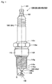
- Fig. 1 is a side view of a spark plug according to Embodiment 1.
- Fig. 2 is an enlarged partial view of the spark plug according to Embodiment 1 showing a center electrode, a ground electrode, and their surrounding portions.
- Fig. 3 is an enlarged partial view of the spark plug according to Embodiment 1 showing a distal end of the ground electrode and its vicinity.
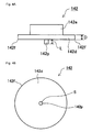
- Figs. 4A and 4B relate to a method of producing the spark plug according to Embodiment 1, wherein Fig. 4A is a side view of an intermediate member used in producing the spark plug, and Fig. 4B is a plan view of the intermediate member as viewed from the projecting portion side.
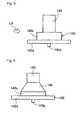
- Fig. 5 relates to the method of producing the spark plug according to Embodiment 1, and is an explanatory view showing a step of laser welding a ground electrode chip to an intermediate member.
- Fig. 6 relates to the method of producing the spark plug according to Embodiment 1, and is an explanatory view showing a state after the ground electrode chip is welded to the intermediate member.
- Fig. 7 relates to the method of producing the spark plug according to Embodiment 1, and is an explanatory view showing a step of projection welding the intermediate member to a ground electrode base material.
- Fig. 8 relates to a spark plug production method according to a modified embodiment, and is a side view of an intermediate member used in producing the spark plug.
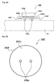
- Figs. 9A and 9B relate to a spark plug according to Embodiment 2, wherein Fig. 9A is a side view of an intermediate member used in producing the spark plug, and Fig. 9B is a plan view of the intermediate member as viewed from the projecting portion side.
- Figs. 10A and 10B relate to a spark plug according to Embodiment 3, wherein Fig. 10A is a side view of an intermediate member used in producing the spark plug, and Fig. 10B is a plan view of the intermediate member as viewed from the projecting portion side.
- Fig. 11 relates to a spark plug according to Embodiment 4, and is a side view of a distal end portion of a ground electrode base material.
- Fig. 1 shows a spark plug 100 according to Embodiment 1.
- Fig. 2 shows a center electrode 130, a ground electrode (outer electrode) 140, and their surrounding portions.
- Fig. 3 shows a distal end of the ground electrode 140 and its vicinity.
- This spark plug 100 is a spark plug for an internal combustion engine which is attached to the cylinder head of the engine.
- the spark plug 100 includes a metallic shell 110, an insulator 120, a center electrode 130, and a ground electrode 140.
- the metallic shell 110 is formed of low carbon steel, and assumes the form of a cylinder extending along the direction of an axis AX.
- the metallic shell 110 includes a flange portion 110f having a large diameter; a tool engagement portion 110m which is located on the proximal end side (upper side in Fig. 1 ) of the flange portion 110f and has a hexagonal cross section and with which a tool is engaged when the spark plug 100 is attached to the cylinder head; and a crimp portion 110n which is located on the proximal end side of the tool engagement portion 110m and used to fix the insulator 120 to the metallic shell 110 through crimping. Further, on the distal end side (lower side in Fig.
- the metallic shell 110 includes a distal end portion 110s which is smaller in diameter than the flange portion 110f and has an attachment screw portion 110g formed on the outer circumference thereof.
- the attachment screw portion 110g is used to screw the spark plug 100 into the cylinder head.
- the insulator 120 is formed of an alumina-based ceramic, and its circumference is surrounded by the metallic shell 110.
- a distal end portion 120s of the insulator 120 projects toward the distal end side (lower side in Fig. 1 ) from a distal end surface 110sc of the metallic shell 110.
- a proximal end portion 120k of the insulator 120 projects toward the proximal end side (upper side in Fig. 1 ) from the crimp portion 110n of the metallic shell 110.
- An axial hole extending along the direction of the axis AX is formed in the insulator 120.
- the center electrode 130 is inserted into and fixed to the distal end side (lower side in Fig. 1 ) of the axial hole, and a metal terminal 150 for supplying high voltage to the center electrode 130 is inserted into and fixed to the proximal end side (upper side in Fig. 1 ) of the axial hole.
- the center electrode 130 is held by the insulator 120 in a state in which the center electrode 130 projects toward the distal end side (lower side in Fig. 1 ) from a distal end surface 120sc of the insulator 120.
- this center electrode 130 is composed of a center electrode base material 131 located on the proximal end side (upper side in Fig. 2 ), and a center electrode chip 133 located on the distal end side (lower side in Fig. 2 ).
- the center electrode base material 131 assumes the form of a cylindrical column, and is composed of a Cu metal portion, and a high-Ni-content alloy portion enclosing the Cu metal portion.
- the Cu metal portion is formed of copper, which has a high thermal conductivity.
- the high-Ni-content alloy portion is formed of a nickel alloy containing nickel in an amount of 80 wt% or more (specifically, INCONEL® 600).
- the center electrode chip 133 assumes the form of a cylindrical column, and is joined to the center electrode base material 131 by means of laser welding such that the center electrode chip 133 projects toward the distal end side (lower side in Fig. 2 ).
- This center electrode chip 133 is formed of a noble metal alloy; specifically, an Ir-Pt alloy.
- the ground electrode 140 is composed of a ground electrode base material (outer electrode base material) 141 located on the distal end side (lower side in these drawings); a ground electrode chip (outer electrode chip) 143 located on the proximal end side (upper side in these drawings); and an intermediate member 142 disposed between the ground electrode base material 141 and the ground electrode chip 143.
- the ground electrode base material 141 is composed of a Cu metal portion 141g, and a high-Ni-content alloy portion 141h enclosing the Cu metal portion 141g.
- the Cu metal portion 141g is formed of copper, which has a high thermal conductivity.
- the high-Ni-content alloy portion 141h is formed of a nickel alloy containing nickel in an amount of 80 wt% or more (specifically, INCONEL® 601).
- a proximal end portion 141k of the ground electrode base material 141 is welded to the distal end surface 110sc of the metallic shell 110, and a distal end portion 141s of the ground electrode base material 141 is bent toward the axis AX such that an inner side surface 141m facing radially inward is disposed opposite the center electrode chip 133 of the center electrode 130.
- the intermediate member 142 (see Figs. 4A and 4B ) is composed of a flange portion (brim portion) 142d which assumes the form of a large diameter cylindrical column and is located on the distal end side (lower side in these drawings); and a cylindrical columnar portion 142e which assumes the form of a cylindrical column having a diameter smaller than that of the flange portion and is located on the proximal end side (upper side in these drawings).
- the entire intermediate member 142 is formed of a nickel alloy containing nickel in an amount of 80 wt% or more (specifically, INCONEL® 601).
- a resistance-welded portion 145 is formed between the intermediate member 142 and the ground electrode base material 141 such that the resistance-welded portion 145 is convex toward the ground electrode base material 141.
- the intermediate member 142 and the ground electrode base material 141 are joined by means of projection welding to be described below, the intermediate member 142 and the ground electrode base material 141 are reliably welded together over a large area around the radial center of the intermediate member 142.
- the ground electrode chip 143 assumes the form of a cylindrical column, is formed of a noble metal alloy; for example, a Pt-Rh alloy, and has a diameter smaller than that of the cylindrical columnar portion 142e.
- the ground electrode chip 143 is joined to the cylindrical columnar portion 142e of the intermediate member 142 such that the ground electrode chip 143 projects toward the proximal end side (upper side in Fig. 3 ) and faces the center electrode chip 133.
- a fused metal portion 146 is formed between the ground electrode chip 143 and the intermediate member 142 as a result fusing and mixing of the ground electrode chip 143 and the intermediate member 142 with each other, and solidifying.
- the height h1 of the cylindrical columnar portion 142e (the distance between the lower end of the fused metal portion 146 and the upper surface of the flange portion 142d as measured along the outer circumferential surface) is 0.05 mm to 0.3 mm.
- the distance h2 between the lower end of the metal fused portion 146 and the upper surface of the flange portion 142d as measured along a center line O of the ground electrode chip 143 is equal to or greater than the height h1 of the cylindrical columnar portion.
- the distance between the metal fused portion 146 and the resistance-welded portion 145 increases toward the center line O.
- the ground electrode chip 143 has a projection length H of 0.80 mm as measured from the inner side surface 141m of the ground electrode base material 141. Further, the projection height h3 of the ground electrode chip 143 from the fused metal portion 146 is made greater than the height h1 of the cylindrical columnar portion. That is, the fused metal portion 146 is formed at a position closer to the upper surface of the flange portion 142d than to the distal end surface of the ground electrode chip 143. This means that the projection height h3 of the ground electrode chip 143 accounts for a greater portion of the predetermined projection height H than does the height h1 of the cylindrical columnar portion, whereby the resistance of the ground electrode 140 to spark-induced ablation can be improved.
- the height h4 of the fused metal portion 146 as measured on the outer circumferential surface is made greater than the height h1 of the cylindrical columnar portion in order to secure a sufficient degree of welding strength.
- the clearance between the ground electrode chip 143 and the center electrode chip 133 serves as a discharge gap G for producing spark discharge.
- a center electrode 130 having a center electrode base material 131 and a center electrode chip 133 is fabricated in a known manner.
- the center electrode chip 133 is laser welded to the center electrode base material 131 to thereby complete the center electrode 130.
- the center electrode 130 is assembled to an insulator 120, which is separately formed, and a terminal metal piece 150, etc., are also assembled to the insulator 120, followed by glass sealing. Further, a metallic shell 110 is prepared, and a bar-shaped ground electrode base material 141 (a ground electrode base material 141 to which an intermediate member 142 and a ground electrode chip 143 have not yet been joined and which has not yet been bent) is joined to the metallic shell 110 in accordance with a known method.
- a bar-shaped ground electrode base material 141 a ground electrode base material 141 to which an intermediate member 142 and a ground electrode chip 143 have not yet been joined and which has not yet been bent
- the insulator 120 to which the center electrode 130, etc., have been assembled, is assembled to the metallic shell 110 to which the ground electrode base material 141 has been joined, and crimping and other necessary operations are performed.
- an intermediate member 142 having a projecting portion 142p shown in Figs. 4A and 4B is fabricated by means of header working. This process corresponds to the projecting portion forming step of the present invention.
- This intermediate member 142 before welding includes a flange portion (brim portion) 142d which has a large diameter and a thickness D of 0.25 mm; a cylindrical columnar portion 142e which has a small diameter and is provided at the radial center of one main face of the flange portion 142d; and a single projecting portion 142p which is provided at the radial center of the other main face of the flange portion 142d and is used for projection welding to be described below.
- the projecting portion 142p is located on the radially inner side of the circumferential edge 142f of the intermediate member 142, and is disposed at the radial center of the intermediate member 142.
- This projecting portion 142p assumes the form of a cylindrical column which has a cross sectional area (average cross sectional area) S of 0.07 mm 2 and a projection length L of 0.10 mm.
- the intermediate member 142 having the projecting portion 142p may be fabricated by means of press working rather than header working.
- a ground electrode chip 143 having a cylindrical columnar shape is prepared. Subsequently, as shown in Fig. 5 , this ground electrode chip 143 is placed on a central portion of the cylindrical columnar portion 142e of the intermediate member 142, and a laser beam LS is applied as indicated by an arrow in Fig. 5 , over a portion or the entire circumference thereof, so as to laser-weld the ground electrode chip 143 and the intermediate member 142. Thus, as shown in Fig. 6 , a fused metal portion 146 is formed between the ground electrode chip 143 and the intermediate member 142 as a result of the two members fusing, mixing with each other, and solidifying.
- the distance h2 between the fused metal portion 146 and the upper surface of the flange 142d as measured along the center line O in Fig. 3 can be made greater than the corresponding distance h1 as measured along the outer circumferential direction. Since the fused metal portion 146 is formed at a position separated from the upper surface of the flange portion 142d, the laser beam LS can be applied along a horizontal direction without being hindered by the flange portion 142d. The lower end of the fused metal portion 146 and the upper surface of the flange portion 142d are separated from each other by a distance corresponding to the height of the remaining cylindrical columnar portion 142e.
- the height h1 of the cylindrical columnar portion 142e as measured after forming the fused metal portion 146 preferably falls within a range of 0.05 mm to 0.3 mm. This height h1 of the cylindrical columnar portion 142e provides an effect of protecting the fused metal portion 146 from heat generated at the time of projection welding to be described below.
- the intermediate member 142 with the ground electrode chip 143 joined thereto is projection-welded to the ground electrode base material 141.
- a resistance welding machine TY is caused to press a peripheral portion of the flange portion 142d of the intermediate member 142 such that the projecting portion 142p of the intermediate member 142 is in pressure contact with the ground electrode base material 141.
- current is applied to the flange portion 142d and is concentrated to the projecting portion 142p so as to projection-weld the intermediate member 142 and the ground electrode base material 141.
- a resistance-welded portion 145 is formed over a large area around the radially central portion such that the resistance-welded portion 145 is convex toward the ground electrode base material 141.
- the distance h2 between the lower end of the previously formed fused metal portion 146 and the upper surface of the flange portion 142d as measured along the center line O of the ground electrode chip 143 is made greater than the distance between the previously formed fused metal portion 146 and the upper surface of the flange portion 142d as measured along the outer circumferential surface (that is, the height h1 of the cylindrical columnar portion). Therefore, the distance between the fused metal portion 146 and the resistance-welded portion 145 can be made sufficiently large in the vicinity of the center line O at which the temperature is likely to become the highest at the time of projection welding.
- the ground electrode 140 is bent toward the axis AX to have a predetermined shape and form a discharge gap G between the ground electrode 140 and the center electrode 130.
- the above-described spark plug 100 is completed.
- the projecting portion 142p is provided on the intermediate member 142, and the intermediate member 142 and the ground electrode base material 141 are projection-welded together by means of the projecting portion 142p.
- This enables the intermediate member 142 and the ground electrode base material 141 to be reliably welded over a large area around the radial center, as compared with conventional resistance welding. Accordingly, when the spark plug 100 thus produced is subjected to a severe thermal cycle test described below, it is possible to prevent formation of a large gap between the intermediate member 142 and the ground electrode base material 141.
- the projecting portion 142p is disposed on the radially inner side of the circumferential edge 142f of the intermediate member 142; for example, at the radial center.
- the intermediate member 142 and the ground electrode base material 141 can be reliably welded over a large area around a radially central portion which contributes to heat transfer, so that heat transfer from the ground electrode chip 143 to the ground electrode base material 141 is improved. Accordingly, when the spark plug 100 thus produced is subjected to a severe thermal cycle test described below, it is possible to prevent the formation of a hollow recess in the fused metal portion 146 between the ground electrode chip 143 and the intermediate member 142, which recess would otherwise have been formed due to high-temperature oxidation.
- the cross sectional area (average cross sectional area) S of the projecting portion 142p is set within a range of 0.03 mm 2 to 0.2 mm 2 inclusive (for example, set to 0.07 mm 2 ), and the projection length L is set within a range of 0.05 mm to 0.2 mm inclusive (for example, set to 0.10 mm). Accordingly, at the time of projection welding, the intermediate member 142 and the ground electrode base material 141 can be reliably welded over a large area.
- the thickness D of the flange portion 142d which is pressed by the resistance welding machine TY, is set to be equal to 0.2 mm or greater (for example, set to 0.25 mm). Accordingly, even when the flange portion is pressed at the time of projection welding, warpage or like deformation does not occur at the flange portion 142d, so that the intermediate member 142 and the outer electrode base material 141 can be welded more reliably.
- the entire intermediate member 142 is formed of a nickel alloy containing nickel in an amount of 80 wt% or more. Therefore, the intermediate member 142 has high thermal conductivity, whereby heat transfer from the ground electrode chip 143 to the ground electrode base material 141 is improved. Accordingly, when the spark plug 100 thus produced is subjected to a severe thermal cycle test described below, it is possible to more reliably prevent formation of a hollow recess in the fused metal portion 146 between the ground electrode chip 143 and the intermediate member 142.
- the projecting portion 142p is provided on the intermediate member 142 by header working. This enables easy and reliable formation of the projecting portion 142p on the intermediate member 142.
- spark plugs 100 of 15 types were manufactured, as Examples of the present invention, in a manner similar to the above-described Embodiment 1.
- the cross sectional area (average cross sectional area) S of the projecting portion 142p was varied within a range of 0.03 mm 2 to 0.25 mm 2
- the projection length L was varied within a range of 0.03 mm to 0.28 mm
- the thickness D of the flange portion 142d of the intermediate member 142 was varied within a range of 0.15 mm to 0.25 mm, as shown in Table 1.
- the spark plugs 100 thus prepared were subjected to a thermal cycle test as follows. Namely, a heating cycle of heating each spark plug at 1000°C for 2 minutes and then naturally cooling the spark plug for 1 minute was repeated 1000 times. After the test, the resistance-welded portion 145 was observed.
- the ground electrode 140 was cut along a plane passing through the axis of the intermediate member 142, and the section was etched. On the section, the joint surface between the intermediate member 142 and the ground electrode base material 141 was observed so as to determine the degree of growth of oxidized scale.
- the ratio of the total length of oxidized scale (the total length of unjoined portions) to the length of the intermediate member 142 (specifically, the flange portion 142d) in a direction perpendicular to the axis was calculated as the ratio of oxidized scale.
- Each sample in which the ratio of oxidized scale was less than 10% was determined to be very good, and was given a grade of "AA" in the table.
- Examples 1 to 15 the results of Examples 1 to 15 will be studied in detail.
- the cross sectional area S of the projecting portion 142p was set to fall within the range of 0.03 mm 2 to 0.20 mm 2 and the projection length L was set to fall within the range of 0.05 mm to 0.20 mm, the ratio of oxidized scale was small; i.e., less than 10%, and a very good result was attained.
- the ratio of oxidized scale was relatively small; i.e., in a range of 10% to 50% inclusive, and a relatively good result was attained.
- the ratio of oxidized scale increased as compared with the above-described Examples 1 to 11. This shows that setting the projection length L within the range of 0.05 mm to 0.20 mm is preferred.
- Example 6 In Examples 6 and 7, in which the thickness D of the flange portion 142d of the intermediate member 142 was set to 0.20 mm or 0.25 mm, the intermediate member 142 did not become warped. Meanwhile, in Example 5, in which the thickness D was set to 0.15 mm, the flange portion 142d of the intermediate member 142 did become warped. These results show that in order to eliminate warpage, the thickness D of the flange portion 142d of the intermediate member 142 is desirably set to 0.20 mm or more.
- FIG. 8 shows an intermediate member 542 used for producing a spark plug 500 according to the present modification.
- the present modification is identical to the above-described Embodiment 1, except that the intermediate member 542 used for producing the spark plug 500 differs from the intermediate member 142 (see Figs. 4A and 4B ) of the above-described Embodiment 1.
- This intermediate member 542 has the same outer shape as that of the intermediate member 142 of the above-described Embodiment 1. That is, the intermediate member 542 is composed of a flange portion (brim portion) 542d which has a large diameter; a cylindrical columnar portion 542e which is provided at the radial center of one main face of the flange portion 542d and which has a small diameter; and a single projecting portion 542p provided at the radial center of the other main face of the flange portion 542d.
- the interior of the intermediate member 542 differs from that of the intermediate member 142 of the above-described Embodiment 1. That is, the intermediate member 542 includes a Cu metal portion 542g formed of Cu, which has a high thermal conductivity, and a high-Ni-content alloy portion 542h enclosing the Cu metal portion 542g.
- the high-Ni-content alloy portion 542h is formed of a nickel alloy containing nickel in an amount of 80 wt% or more (for example, INCONEL® 601).
- the intermediate member 542 includes the Cu metal portion 542g having a very high heat conductivity, the heat conductivity of the entire intermediate member 542 is also high, so that heat transfer from the ground electrode chip 143 to the ground electrode base material 141 is improved. Accordingly, when a severe thermal cycle test as described above is carried out, it is possible to more reliably prevent formation of a hollow recess in the fused metal portion between the ground electrode chip 143 and the intermediate member 542.
- FIGs. 9A and 9B show an intermediate member 242 used for producing a spark plug 200 according to the present Embodiment 2.
- the present Embodiment 2 is basically identical to the above-described Embodiment 1, except that the intermediate member 242 used for producing the spark plug 200 differs from the intermediate member 142 (see Figs. 4A and 4B ) of the above-described Embodiment 1.
- This intermediate member 242 includes a Cu metal portion 242g formed of copper, and a high-Ni-content alloy portion 242h formed of a nickel alloy and covering the Cu metal portion 242g.
- the intermediate member 242 has a flange portion 242d having a large diameter and a cylindrical columnar portion 242e having a small diameter.
- a plurality of (two) projecting portions 242p for performing projection welding are provided on the flange portion 242d on the radially inner side of the circumferential edge 242f of the intermediate member 242.
- FIGs. 10A and 10B show an intermediate member 342 used for producing a spark plug 300 according to the present Embodiment 3.
- the present Embodiment 3 is basically identical to the above-described Embodiments 1 and 2, except that the intermediate member 342 used for producing the spark plug 300 differs from the intermediate members 142 and 242 of the above-described Embodiments 1 and 2.
- This intermediate member 342 includes a Cu metal portion 342g formed of copper, and a high-Ni-content alloy portion 342h formed of a nickel alloy and covering the Cu metal portion 342g.
- the intermediate member 342 has a flange portion 342d having a large diameter; a cylindrical columnar portion 342e having a small diameter; and a taper portion 342f located therebetween.
- a single projecting portion 342p for performing projection welding is provided at the radial center of the flange portion 342d.
- FIG. 11 shows a ground electrode base material 441 used for producing a spark plug 400 according to the present Embodiment 4.
- the present Embodiment 4 is basically identical to the above-described Embodiments 1 or the like, except that the ground electrode base material 441 differs from the ground electrode base material 141 of the above-described Embodiments 1 to 3.
- This ground electrode base material 441 includes a Cu metal portion 441 g formed of copper, and a high-Ni-content alloy portion 441h formed of a nickel alloy and covering the Cu metal portion 441 g.
- a single projecting portion 441p for performing projection welding is provided at a predetermined position on an inner side surface 441m of a distal end portion 441s of the ground electrode base material 441.
- the projecting portion 441p is disposed on the radially inner side of the circumferential edge of the intermediate member 142; for example, at the radial center thereof. In this manner, the intermediate member 142, to which the ground electrode chip 143 has been joined, is placed on the ground electrode base material 441.
- the intermediate member 142 and the ground electrode base material 441 can be reliably welded together over a large area around the radial center of the intermediate member 142.
- the ground electrode base material 441 including the projecting portion 441p according to the present Embodiment 4 can be formed by means of press working. Portions similar to those of any one of the above-described Embodiments 1 to 3 achieve the same action and effects as those of the above-described Embodiments 1 to 3.
- the projecting portion (142p, 242p, 342p) is provided only on the intermediate member (142, 242, 342) alone, and in the above-described Embodiment 4, the projecting portion (441 p) is only provided on the ground electrode base material (441) alone.
- a projecting portion may be provided on both of the intermediate member and the ground electrode base material. In this case as well, the intermediate member and the ground electrode base material can be reliably welded over a large area through projection welding using one or more of these projecting portions.
Abstract
Description
- The present invention relates to a method for producing a spark plug for an internal combustion engine and to a spark plug manufactured by the method, and more particularly, to a method for producing a spark plug having an outer electrode in which an outer electrode chip is joined to an outer electrode base material via an intermediate member and to a spark plug manufactured by the method.
- Conventionally known spark plugs include spark plugs having a center electrode and an outer electrode in which an outer electrode chip is joined to an outer electrode base material via an intermediate member. For example, Patent Document 1 and Patent Document 2 disclose such a spark plug.
- In Patent Document 1, the outer electrode of a spark plug is produced as follows. That is, a chip-shaped electrode material (outer electrode chip) which is resistant to spark-induced ablation is joined to an end of a bar-shaped member (intermediate member) made of a base metal resistant to corrosion, by means of TIG welding (tungsten inert gas welding) or laser welding. Subsequently, the corrosion-resistant base metal member (intermediate member) is cut to an appropriate dimension. The flat surfaces of the corrosion-resistant base metal member (intermediate member) and the outer electrode (outer electrode base material) are brought into contact with each other, and welded together through resistance welding, whereby the outer electrode is formed (see Claims and other sections of Patent Document 1).
- In Patent Document 2, the outer electrode is produced as follows. That is, an intermediate member having first and second parallel surfaces is fabricated in advance, and a chip (outer electrode chip) is laser-welded to the first surface of the intermediate member. Subsequently, the second surface of the intermediate member and a joint surface of the electrode base material (outer electrode base material) are brought into contact with each other, and are welded together through resistance welding, whereby the outer electrode is formed (see Claims and other sections of Patent Document 2). The resistance welding between the intermediate member and the electrode base material (outer electrode base material) is performed by supplying current thereto while pressing a circumferential edge portion of the intermediate member by means of an electric resistance welding machine (see
Fig. 4 and its description in Patent Document 2). - [Patent Document 1] Japanese Patent Application Laid-Open (kokai) No. H8-298178
- [Patent Document 2] Japanese Patent Application Laid-Open (kokai) No.
2004-134209 - However, when a spark plug produced in accordance with Patent Document 1 or 2 is subjected to a thermal cycle test in which a thermal cycle of heating the spark plug to a high temperature and then naturally cooling is repeated a large number of times, a large gap may be produced between the intermediate member and the outer electrode base material at a radially central portion thereof. Such a gap results in deteriorated reliability of the joint between the intermediate member and the outer electrode base material. Further, in some cases, a hollow portion is generated in a fused metal alloy portion between the outer electrode chip and the intermediate member at an outer periphery of the fused metal portion.
- Conceivably, the reason why a large gap is produced between the intermediate member and the outer electrode base material at a radially central portion thereof is as follows. That is, when the intermediate member and the outer electrode base material are resistance-welded, a circumferential edge portion of the intermediate member is pressed against the outer electrode base material. Therefore, at that circumferential edge portion, the intermediate member and the outer electrode base material are mixedly fused and welded without fail. However, since no pressure is applied to a radially central portion of the intermediate member, at that central portion, the intermediate member and the outer electrode base material are not reliably welded in some instances. Therefore, when a thermal cycle test is performed, due to thermal stress produced at that time, a large gap tends to form at a radially central portion at which the intermediate member and the outer electrode base material are not reliably welded.
- Further, the reason why a hollow portion is formed in the fused metal portion between the outer electrode chip and the intermediate member is as follows. That is, when a large gap is present between the intermediate member and the outer electrode base material at a radially central portion thereof as described above, transfer of heat from the outer electrode chip to the outer electrode base material deteriorates. Therefore, during a thermal cycle test, the fused metal portion between the outer electrode chip and the intermediate member is exposed to high temperature. As a result, the fused metal portion is subject to high-temperature oxidation, so that an alloy which constitutes the fused metal portion is gradually consumed, and a hollow portion is formed. Further, in the spark plug of Patent Document 1, in order to secure a sufficient joining area between the intermediate member and the outer electrode base material, the entire intermediate member must be increased in size. In contrast, in the spark plug of Patent Document 2, the intermediate member has a stepped structure; i.e., has a cylindrical columnar portion having a smaller diameter and a flange portion having a larger diameter. Thus, it is possible to adjust the diameter of the flange so as to secure a sufficient joint area, while matching the diameter of the cylindrical columnar portion with the diameter of the outer electrode chip. However, since the intermediate member is configured such that the cylindrical columnar portion disappears during laser welding, and only the flange portion is left after the laser welding, the incident angle of a laser beam during the laser welding is likely to be restricted by the flange portion.
- The present invention has been made in view of the above circumstances, and an object thereof is to provide a method for producing a spark plug having an outer electrode chip joined to an outer electrode base material via an intermediate member, wherein a large gap is hardly generated between the intermediate member and the outer electrode base material, and wherein a hollow recess is hardly generated in a fused metal portion between the outer electrode chip and the intermediate member even when subjected to severe thermal cycling. Another object of the invention is to provide a spark plug manufactured by the production method.
- The above object of the invention has been achieved by providing, in a first aspect, a method for producing a spark plug which includes a center electrode and an outer electrode facing the center electrode via a discharge gap and configured such that an outer electrode chip is joined to an outer electrode base material via an intermediate member, the method comprising projection-welding the intermediate member to the outer electrode base material by means of a projecting portion provided on at least one of the intermediate member and the outer electrode base material.
- The production method according to the present invention comprises a projection welding step of projection-welding the intermediate member to the outer electrode base material by means of a projecting portion provided on at least one of the intermediate member and the outer electrode base material. This enables the intermediate member and the outer electrode base material to be reliably welded together over a wider area as compared with a case where a conventional resistance welding technique is employed. Accordingly, when a spark plug thus produced undergoes a severe thermal cycle test, it is possible to prevent a large gap from forming between the intermediate member and the outer electrode base material. Further, since the intermediate member and the outer electrode base material are reliably welded together over a wide area, heat transfer from the outer electrode chip to the outer electrode base material is improved. Accordingly, when a spark plug thus produced undergoes a severe thermal cycle test, it is possible to prevent formation of a hollow recess in a fused metal portion between the outer electrode chip and the intermediate member, which hollow recess would otherwise be generated due to high-temperature oxidation.
- Notably, the projecting portion may be provided on the intermediate member or the outer electrode base material only, or provided on both of them. Further, a single projecting portion or a plurality of projecting portions may be provided. Also, the shape of the projecting portion may be freely changed, so long as the selected shape is suitable for projection welding. For example, the projecting portion may assume a circular columnar shape or a square columnar shape. Moreover, the projecting portion may have a spherical distal end surface or a pointed distal end.
- In a preferred embodiment, the projecting portion is provided on at least one of the intermediate member and the outer electrode base material such that, at the time of projection welding, the projecting portion is located radially inward of a circumferential edge of the intermediate member.
- As described above, if a large gap is generated between the intermediate member and the outer electrode base, in particular, at a radially central portion thereof, transfer of heat from the outer electrode chip to the outer electrode base material deteriorates, so that during a thermal cycle test, a hollow recess is likely to be generated in a fused metal portion between the outer electrode chip and the intermediate member due to high-temperature oxidation.
- In contrast, according to the present invention, the projecting portion is provided on at least one of the intermediate member and the outer electrode base material such that, at the time of projection welding, the projecting portion is located radially inward of a circumferential edge of the intermediate member. Therefore, when the above-described projection welding is carried out, portions of the intermediate member and the outer electrode base material located on the radially inner side of the circumferential edge of the intermediate member are likely to be reliably welded together, so as to prevent a large gap from forming between the radially inner portions of the intermediate member and the outer electrode base material. Accordingly, even when a spark plug thus produced undergoes a severe thermal cycle test, it is possible to more reliably prevent a hollow recess from forming in a fused metal portion between the outer electrode chip and the intermediate member, which recess would otherwise be generated due to high-temperature oxidation.
- In the above-described method for producing a spark plug, preferably, the projecting portion is provided on at least one of the intermediate member and the outer electrode base material such that, at the time of projection welding, the projecting portion is located at a radially central portion of the intermediate member.
- According to the present invention, the projecting portion is provided on at least one of the intermediate member and the outer electrode base material such that, at the time of projection welding, the projecting portion is located at a radially central portion of the intermediate member. Therefore, when the above-described projection welding is carried out, portions of the intermediate member and the outer electrode base material located at a radially central portion of the intermediate member are likely to be reliably welded together so as to enhance heat transfer. Thus, formation of a large gap between the radially central portions of the intermediate member and the outer electrode base material is prevented. Accordingly, even when a spark plug thus produced undergoes a severe thermal cycle test, it is possible to even more reliably prevent a hollow recess from forming in a fused metal portion between the outer electrode chip and the intermediate member, which recess would otherwise be generated due to high-temperature oxidation.
- In yet another preferred embodiment, the projecting portion has an average cross sectional area of 0.03 mm2 to 0.2 mm2 inclusive, as measured perpendicular to an axial direction of the projecting portion, and a projection length of 0.05 mm to 0.2 mm inclusive.
- When the average cross sectional area of the projecting portion is less than 0.03 mm2 and excessively small or is greater than 0.2 mm2 or when the projection length is less than 0.05 mm and excessively small or is greater than 0.2 mm, at the time of projection welding, some difficulty may be encountered in reliably welding the intermediate member to the outer electrode base material over a large area.
- In contrast, according to the present invention, the projecting portion has an average cross sectional area of 0.03 mm2 to 0.2 mm2 inclusive and a projection length of 0.05 mm to 0.2 mm inclusive, whereby, at the time of projection welding, the intermediate member and the outer electrode base material can more reliably be welded together over a large area.
- Notably, the term "average cross sectional area" refers to a value obtained by averaging the area of a cross section of the projecting portion taken perpendicular to the axial direction of the projecting portion, from an axially distal end to an axially proximal end of the projecting portion. Further, in a case where a plurality of projecting portions are provided, the term "average cross sectional area" refers to the sum of the respective average cross sectional areas of these projecting portions.
- In yet another preferred embodiment, the method comprises pressing a brim portion of the intermediate member by a resistance welding machine at the time of projection welding, the brim portion having a thickness of 0.2 mm or greater.
- If the thickness of the brim portion of the intermediate member, which portion is pressed by a resistance welding machine is less than 0.2 mm and excessively small, at the time of projection welding, deformation such as warpage may be generated at the brim portion, resulting in a deficiency associated with welding.
- In contrast, according to the present invention, the brim portion, which is pressed by a resistance welding machine, has a thickness of 0.2 mm or greater. Accordingly, at the time of projection welding, no deformation results at the brim portion, so that the intermediate member and the outer electrode base material can be welded together more reliably.
- In yet another preferred embodiment, the intermediate member is formed of a nickel alloy containing nickel in an amount of 80 wt% or more.
- As described above, in a case where heat transfer from the outer electrode chip to the outer electrode base material is poor, when a severe thermal cycle test is carried out, a hollow recess is likely to be generated in a fused metal portion between the outer electrode chip and the intermediate member due to high-temperature oxidation.
- In order to overcome this drawback, in the present invention, the intermediate member is formed of a nickel alloy containing nickel in an amount of 80 wt% or more. Therefore, the intermediate member has a high thermal conductivity, so that the heat transfer from the outer electrode chip to the outer electrode base material is improved. Accordingly, even when a severe thermal cycle test is carried out, it is possible to more reliably prevent a hollow recess from forming in a fused metal portion between the outer electrode chip and the intermediate member.
- In yet another preferred embodiment, the intermediate member comprises a nickel alloy portion formed of a nickel alloy, and a copper metal portion embedded in the nickel alloy portion.
- As described above, in a case where heat transfer from the outer electrode chip to the outer electrode base material is poor, when a severe thermal cycle test is carried out, a hollow recess is likely to be generated in a fused metal portion between the outer electrode chip and the intermediate member due to high-temperature oxidation.
- In order to overcome this drawback, in the present invention, the intermediate member includes a nickel alloy portion formed of a nickel alloy, and a copper metal portion embedded in the nickel alloy portion. Since the intermediate member includes a copper metal portion which has a considerably high thermal conductivity, the thermal conductivity of the entire intermediate member is also high, so that heat transfer from the outer electrode chip to the outer electrode base material is improved. Accordingly, even when a severe thermal cycle test is carried out, it is possible to more reliably prevent a hollow recess from forming in a fused metal portion between the outer electrode chip and the intermediate member.
- In yet another preferred embodiment, the method comprises forming the projecting portion on at least one of the intermediate member and the outer electrode base material by means of header working or press working.
- According to the present invention, the projecting portion is provided on at least one of the intermediate member and the outer electrode base material by means of header working (see, for example,
U.S. Patent Nos. 6,597,089 ,7,084,558 and7,321,137 incorporated herein by reference) or press working (see, for example,U.S. Patent Nos. 6,960,729 ,6,583,366 and6,359,332 incorporated herein by reference). This step allows easy and reliable formation of the projecting portion. - In a second aspect, the present invention provides a spark plug comprising a center electrode and an outer electrode. The outer electrode includes a noble metal chip facing the center electrode via a discharge gap; an outer electrode base material; an intermediate member for connecting the noble metal chip and the outer electrode base material; and a fused metal portion formed between the noble metal chip and the intermediate member by means of laser welding. The intermediate member includes a cylindrical columnar portion which is joined to the noble metal chip, and a flange portion which is joined to the outer electrode base material and which has a diameter greater than that of the cylindrical columnar portion.
- According to the present invention, the spark plug is configured such that the cylindrical columnar portion remains after completion of laser welding. Therefore, at the time of laser welding, the flange portion does not restrict the incident angle of a laser beam, so that the fused metal portion can be readily formed. In addition, the fused metal portion can be separated from the flange portion by a certain distance or more. In such a case, deterioration of the fused metal portion hardly occurs when the intermediate member is joined to the outer electrode base material via the flange portion by means of resistance welding or the like. Notably, in a preferred embodiment of the second aspect, the spark plug satisfies a relation 0.05 mm ≤ h1 ≤ 0.3 mm where h1 represents the height of the cylindrical columnar portion.
- In yet another preferred embodiment of the second aspect, the fused metal portion is formed over the entirety of a joint surface between the noble metal chip and the cylindrical columnar portion, and a relation h1 < h2 is satisfied, where h2 represents a distance between a lower end of the fused metal portion and an upper surface of the flange portion as measured along a center line of the noble metal chip. In particular, in a case where the projection portion used for projection welding between the intermediate member and the outer electrode base material is provided at the center of a lower surface of the flange portion, the temperature becomes highest in the vicinity of the center of the flange portion. At such a central portion, the fused metal portion can become separated from the high temperature portion.
- In yet another preferred embodiment of the second aspect, the spark plug satisfies a relation h3 > h1 where h3 represents a projection height of the noble metal chip as measured from the fused metal portion. In this manner, the projection height h3 of the ground electrode chip accounts for a greater portion of the predetermined projection height H (see
Fig. 3 ) than does the height h1 of the cylindrical columnar portion, whereby the resistance of the outer electrode to spark-induced ablation can be improved. -
Fig. 1 is a side view of a spark plug according to Embodiment 1. -
Fig. 2 is an enlarged partial view of the spark plug according to Embodiment 1 showing a center electrode, a ground electrode, and their surrounding portions. -
Fig. 3 is an enlarged partial view of the spark plug according to Embodiment 1 showing a distal end of the ground electrode and its vicinity. -
Figs. 4A and 4B relate to a method of producing the spark plug according to Embodiment 1, whereinFig. 4A is a side view of an intermediate member used in producing the spark plug, andFig. 4B is a plan view of the intermediate member as viewed from the projecting portion side. -
Fig. 5 relates to the method of producing the spark plug according to Embodiment 1, and is an explanatory view showing a step of laser welding a ground electrode chip to an intermediate member. -
Fig. 6 relates to the method of producing the spark plug according to Embodiment 1, and is an explanatory view showing a state after the ground electrode chip is welded to the intermediate member. -
Fig. 7 relates to the method of producing the spark plug according to Embodiment 1, and is an explanatory view showing a step of projection welding the intermediate member to a ground electrode base material. -
Fig. 8 relates to a spark plug production method according to a modified embodiment, and is a side view of an intermediate member used in producing the spark plug. -
Figs. 9A and 9B relate to a spark plug according to Embodiment 2, whereinFig. 9A is a side view of an intermediate member used in producing the spark plug, andFig. 9B is a plan view of the intermediate member as viewed from the projecting portion side. -
Figs. 10A and 10B relate to a spark plug according to Embodiment 3, whereinFig. 10A is a side view of an intermediate member used in producing the spark plug, andFig. 10B is a plan view of the intermediate member as viewed from the projecting portion side. -
Fig. 11 relates to a spark plug according to Embodiment 4, and is a side view of a distal end portion of a ground electrode base material. - Reference numerals used to identify various structural elements of the drawings include:
- 100, 200, 300, 400, 500: spark plug
- 130: center electrode
- 131: center electrode base material
- 133: center electrode chip
- 140: ground electrode (outer electrode)
- 141, 441: ground electrode base material (outer electrode base material)
- 141 g, 441 g: Cu metal portion
- 141h, 441 h: high-Ni-content alloy portion
- 142, 242, 342, 542: intermediate member
- 142d, 242d, 342d, 542d: flange portion (brim portion)
- 242g, 342g, 542g: Cu metal portion
- 242h, 342h, 542h: high-Ni-content alloy portion
- 142p, 242p, 342p, 441p, 542p: projecting portion
- 143: ground electrode chip (outer electrode chip)
- 145: resistance-welded portion
- 146: fused metal portion
- AX: axis
- G: discharge gap
- L: projection length
- D: thickness
- TY: resistance welding machine
- Embodiments of the present invention will now be described in detail with reference to the drawings. However, the present invention should not be construed as being limited thereto.
-
Fig. 1 shows aspark plug 100 according to Embodiment 1.Fig. 2 shows acenter electrode 130, a ground electrode (outer electrode) 140, and their surrounding portions.Fig. 3 shows a distal end of theground electrode 140 and its vicinity. Thisspark plug 100 is a spark plug for an internal combustion engine which is attached to the cylinder head of the engine. - As shown in
Fig. 1 , thespark plug 100 includes ametallic shell 110, aninsulator 120, acenter electrode 130, and aground electrode 140. - The
metallic shell 110 is formed of low carbon steel, and assumes the form of a cylinder extending along the direction of an axis AX. Themetallic shell 110 includes aflange portion 110f having a large diameter; atool engagement portion 110m which is located on the proximal end side (upper side inFig. 1 ) of theflange portion 110f and has a hexagonal cross section and with which a tool is engaged when thespark plug 100 is attached to the cylinder head; and acrimp portion 110n which is located on the proximal end side of thetool engagement portion 110m and used to fix theinsulator 120 to themetallic shell 110 through crimping. Further, on the distal end side (lower side inFig. 1 ) of theflange portion 110f, themetallic shell 110 includes adistal end portion 110s which is smaller in diameter than theflange portion 110f and has anattachment screw portion 110g formed on the outer circumference thereof. Theattachment screw portion 110g is used to screw thespark plug 100 into the cylinder head. - The
insulator 120 is formed of an alumina-based ceramic, and its circumference is surrounded by themetallic shell 110. Adistal end portion 120s of theinsulator 120 projects toward the distal end side (lower side inFig. 1 ) from a distal end surface 110sc of themetallic shell 110. Aproximal end portion 120k of theinsulator 120 projects toward the proximal end side (upper side inFig. 1 ) from thecrimp portion 110n of themetallic shell 110. An axial hole extending along the direction of the axis AX is formed in theinsulator 120. Thecenter electrode 130 is inserted into and fixed to the distal end side (lower side inFig. 1 ) of the axial hole, and ametal terminal 150 for supplying high voltage to thecenter electrode 130 is inserted into and fixed to the proximal end side (upper side inFig. 1 ) of the axial hole. - The
center electrode 130 is held by theinsulator 120 in a state in which thecenter electrode 130 projects toward the distal end side (lower side inFig. 1 ) from a distal end surface 120sc of theinsulator 120. As shown inFig. 2 , thiscenter electrode 130 is composed of a centerelectrode base material 131 located on the proximal end side (upper side inFig. 2 ), and acenter electrode chip 133 located on the distal end side (lower side inFig. 2 ). - The center
electrode base material 131 assumes the form of a cylindrical column, and is composed of a Cu metal portion, and a high-Ni-content alloy portion enclosing the Cu metal portion. The Cu metal portion is formed of copper, which has a high thermal conductivity. The high-Ni-content alloy portion is formed of a nickel alloy containing nickel in an amount of 80 wt% or more (specifically, INCONEL® 600). - The
center electrode chip 133 assumes the form of a cylindrical column, and is joined to the centerelectrode base material 131 by means of laser welding such that thecenter electrode chip 133 projects toward the distal end side (lower side inFig. 2 ). Thiscenter electrode chip 133 is formed of a noble metal alloy; specifically, an Ir-Pt alloy. - Meanwhile, as shown in
Figs. 2 and3 , theground electrode 140 is composed of a ground electrode base material (outer electrode base material) 141 located on the distal end side (lower side in these drawings); a ground electrode chip (outer electrode chip) 143 located on the proximal end side (upper side in these drawings); and anintermediate member 142 disposed between the groundelectrode base material 141 and theground electrode chip 143. - The ground
electrode base material 141 is composed of aCu metal portion 141g, and a high-Ni-content alloy portion 141h enclosing theCu metal portion 141g. TheCu metal portion 141g is formed of copper, which has a high thermal conductivity. The high-Ni-content alloy portion 141h is formed of a nickel alloy containing nickel in an amount of 80 wt% or more (specifically, INCONEL® 601). Aproximal end portion 141k of the groundelectrode base material 141 is welded to the distal end surface 110sc of themetallic shell 110, and adistal end portion 141s of the groundelectrode base material 141 is bent toward the axis AX such that aninner side surface 141m facing radially inward is disposed opposite thecenter electrode chip 133 of thecenter electrode 130. - The intermediate member 142 (see
Figs. 4A and 4B ) is composed of a flange portion (brim portion) 142d which assumes the form of a large diameter cylindrical column and is located on the distal end side (lower side in these drawings); and acylindrical columnar portion 142e which assumes the form of a cylindrical column having a diameter smaller than that of the flange portion and is located on the proximal end side (upper side in these drawings). The entireintermediate member 142 is formed of a nickel alloy containing nickel in an amount of 80 wt% or more (specifically, INCONEL® 601). - Since the intermediate member 142 (
flange portion 142d) and the groundelectrode base material 141 are joined by welding, as shown inFig. 3 , a resistance-weldedportion 145 is formed between theintermediate member 142 and the groundelectrode base material 141 such that the resistance-weldedportion 145 is convex toward the groundelectrode base material 141. In particular, in the present Embodiment 1, since theintermediate member 142 and the groundelectrode base material 141 are joined by means of projection welding to be described below, theintermediate member 142 and the groundelectrode base material 141 are reliably welded together over a large area around the radial center of theintermediate member 142. - The ground electrode chip 143 (see
Fig. 5 ) assumes the form of a cylindrical column, is formed of a noble metal alloy; for example, a Pt-Rh alloy, and has a diameter smaller than that of thecylindrical columnar portion 142e. Theground electrode chip 143 is joined to thecylindrical columnar portion 142e of theintermediate member 142 such that theground electrode chip 143 projects toward the proximal end side (upper side inFig. 3 ) and faces thecenter electrode chip 133. Since theground electrode chip 143 and theintermediate member 142 are joined by means of laser welding, a fusedmetal portion 146 is formed between theground electrode chip 143 and theintermediate member 142 as a result fusing and mixing of theground electrode chip 143 and theintermediate member 142 with each other, and solidifying. The height h1 of thecylindrical columnar portion 142e (the distance between the lower end of the fusedmetal portion 146 and the upper surface of theflange portion 142d as measured along the outer circumferential surface) is 0.05 mm to 0.3 mm. The distance h2 between the lower end of the metal fusedportion 146 and the upper surface of theflange portion 142d as measured along a center line O of theground electrode chip 143 is equal to or greater than the height h1 of the cylindrical columnar portion. Thus, the distance between the metal fusedportion 146 and the resistance-weldedportion 145 increases toward the center line O. - The
ground electrode chip 143 has a projection length H of 0.80 mm as measured from theinner side surface 141m of the groundelectrode base material 141. Further, the projection height h3 of theground electrode chip 143 from the fusedmetal portion 146 is made greater than the height h1 of the cylindrical columnar portion. That is, the fusedmetal portion 146 is formed at a position closer to the upper surface of theflange portion 142d than to the distal end surface of theground electrode chip 143. This means that the projection height h3 of theground electrode chip 143 accounts for a greater portion of the predetermined projection height H than does the height h1 of the cylindrical columnar portion, whereby the resistance of theground electrode 140 to spark-induced ablation can be improved. - Moreover, the height h4 of the fused
metal portion 146 as measured on the outer circumferential surface is made greater than the height h1 of the cylindrical columnar portion in order to secure a sufficient degree of welding strength. - The clearance between the
ground electrode chip 143 and thecenter electrode chip 133 serves as a discharge gap G for producing spark discharge. - Next, a method for producing the above-described
spark plug 100 will be described. - First, a
center electrode 130 having a centerelectrode base material 131 and acenter electrode chip 133 is fabricated in a known manner. For example, thecenter electrode chip 133 is laser welded to the centerelectrode base material 131 to thereby complete thecenter electrode 130. - Subsequently, in accordance with a known method, the
center electrode 130 is assembled to aninsulator 120, which is separately formed, and aterminal metal piece 150, etc., are also assembled to theinsulator 120, followed by glass sealing. Further, ametallic shell 110 is prepared, and a bar-shaped ground electrode base material 141 (a groundelectrode base material 141 to which anintermediate member 142 and aground electrode chip 143 have not yet been joined and which has not yet been bent) is joined to themetallic shell 110 in accordance with a known method. After that, in accordance with a known method, theinsulator 120, to which thecenter electrode 130, etc., have been assembled, is assembled to themetallic shell 110 to which the groundelectrode base material 141 has been joined, and crimping and other necessary operations are performed. - Separately, an
intermediate member 142 having a projectingportion 142p shown inFigs. 4A and 4B is fabricated by means of header working. This process corresponds to the projecting portion forming step of the present invention. Thisintermediate member 142 before welding includes a flange portion (brim portion) 142d which has a large diameter and a thickness D of 0.25 mm; acylindrical columnar portion 142e which has a small diameter and is provided at the radial center of one main face of theflange portion 142d; and a single projectingportion 142p which is provided at the radial center of the other main face of theflange portion 142d and is used for projection welding to be described below. Accordingly, the projectingportion 142p is located on the radially inner side of thecircumferential edge 142f of theintermediate member 142, and is disposed at the radial center of theintermediate member 142. This projectingportion 142p assumes the form of a cylindrical column which has a cross sectional area (average cross sectional area) S of 0.07 mm2 and a projection length L of 0.10 mm. - Notably, in the projecting portion forming step, the
intermediate member 142 having the projectingportion 142p may be fabricated by means of press working rather than header working. - Separately, a
ground electrode chip 143 having a cylindrical columnar shape is prepared. Subsequently, as shown inFig. 5 , thisground electrode chip 143 is placed on a central portion of thecylindrical columnar portion 142e of theintermediate member 142, and a laser beam LS is applied as indicated by an arrow inFig. 5 , over a portion or the entire circumference thereof, so as to laser-weld theground electrode chip 143 and theintermediate member 142. Thus, as shown inFig. 6 , a fusedmetal portion 146 is formed between theground electrode chip 143 and theintermediate member 142 as a result of the two members fusing, mixing with each other, and solidifying. Notably, since the laser beam LS is applied generally horizontally rather than obliquely, the distance h2 between the fusedmetal portion 146 and the upper surface of theflange 142d as measured along the center line O inFig. 3 can be made greater than the corresponding distance h1 as measured along the outer circumferential direction. Since the fusedmetal portion 146 is formed at a position separated from the upper surface of theflange portion 142d, the laser beam LS can be applied along a horizontal direction without being hindered by theflange portion 142d. The lower end of the fusedmetal portion 146 and the upper surface of theflange portion 142d are separated from each other by a distance corresponding to the height of the remainingcylindrical columnar portion 142e. The height h1 of thecylindrical columnar portion 142e as measured after forming the fusedmetal portion 146 preferably falls within a range of 0.05 mm to 0.3 mm. This height h1 of thecylindrical columnar portion 142e provides an effect of protecting the fusedmetal portion 146 from heat generated at the time of projection welding to be described below. - Next, in a projection welding step, as shown in
Fig. 7 , theintermediate member 142 with theground electrode chip 143 joined thereto is projection-welded to the groundelectrode base material 141. Specifically, a resistance welding machine TY is caused to press a peripheral portion of theflange portion 142d of theintermediate member 142 such that the projectingportion 142p of theintermediate member 142 is in pressure contact with the groundelectrode base material 141. In this state, current is applied to theflange portion 142d and is concentrated to the projectingportion 142p so as to projection-weld theintermediate member 142 and the groundelectrode base material 141. Thus, as shown inFig. 3 , a resistance-weldedportion 145 is formed over a large area around the radially central portion such that the resistance-weldedportion 145 is convex toward the groundelectrode base material 141. Notably, the distance h2 between the lower end of the previously formed fusedmetal portion 146 and the upper surface of theflange portion 142d as measured along the center line O of theground electrode chip 143 is made greater than the distance between the previously formed fusedmetal portion 146 and the upper surface of theflange portion 142d as measured along the outer circumferential surface (that is, the height h1 of the cylindrical columnar portion). Therefore, the distance between the fusedmetal portion 146 and the resistance-weldedportion 145 can be made sufficiently large in the vicinity of the center line O at which the temperature is likely to become the highest at the time of projection welding. - After that, the
ground electrode 140 is bent toward the axis AX to have a predetermined shape and form a discharge gap G between theground electrode 140 and thecenter electrode 130. Thus, the above-describedspark plug 100 is completed. - As described above, in the present Embodiment 1, the projecting
portion 142p is provided on theintermediate member 142, and theintermediate member 142 and the groundelectrode base material 141 are projection-welded together by means of the projectingportion 142p. This enables theintermediate member 142 and the groundelectrode base material 141 to be reliably welded over a large area around the radial center, as compared with conventional resistance welding. Accordingly, when thespark plug 100 thus produced is subjected to a severe thermal cycle test described below, it is possible to prevent formation of a large gap between theintermediate member 142 and the groundelectrode base material 141. - In particular, the projecting
portion 142p is disposed on the radially inner side of thecircumferential edge 142f of theintermediate member 142; for example, at the radial center. By virtue of this arrangement, theintermediate member 142 and the groundelectrode base material 141 can be reliably welded over a large area around a radially central portion which contributes to heat transfer, so that heat transfer from theground electrode chip 143 to the groundelectrode base material 141 is improved. Accordingly, when thespark plug 100 thus produced is subjected to a severe thermal cycle test described below, it is possible to prevent the formation of a hollow recess in the fusedmetal portion 146 between theground electrode chip 143 and theintermediate member 142, which recess would otherwise have been formed due to high-temperature oxidation. - Further, in the present Embodiment 1, the cross sectional area (average cross sectional area) S of the projecting
portion 142p is set within a range of 0.03 mm2 to 0.2 mm2 inclusive (for example, set to 0.07 mm2), and the projection length L is set within a range of 0.05 mm to 0.2 mm inclusive (for example, set to 0.10 mm). Accordingly, at the time of projection welding, theintermediate member 142 and the groundelectrode base material 141 can be reliably welded over a large area. - Further, the thickness D of the
flange portion 142d, which is pressed by the resistance welding machine TY, is set to be equal to 0.2 mm or greater (for example, set to 0.25 mm). Accordingly, even when the flange portion is pressed at the time of projection welding, warpage or like deformation does not occur at theflange portion 142d, so that theintermediate member 142 and the outerelectrode base material 141 can be welded more reliably. - Moreover, in the present Embodiment 1, the entire
intermediate member 142 is formed of a nickel alloy containing nickel in an amount of 80 wt% or more. Therefore, theintermediate member 142 has high thermal conductivity, whereby heat transfer from theground electrode chip 143 to the groundelectrode base material 141 is improved. Accordingly, when thespark plug 100 thus produced is subjected to a severe thermal cycle test described below, it is possible to more reliably prevent formation of a hollow recess in the fusedmetal portion 146 between theground electrode chip 143 and theintermediate member 142. - Further, in the present Embodiment 1, the projecting
portion 142p is provided on theintermediate member 142 by header working. This enables easy and reliable formation of the projectingportion 142p on theintermediate member 142. - In order to verify the effects of the present embodiment,
spark plugs 100 of 15 types were manufactured, as Examples of the present invention, in a manner similar to the above-described Embodiment 1. In these Examples, the cross sectional area (average cross sectional area) S of the projectingportion 142p was varied within a range of 0.03 mm2 to 0.25 mm2, the projection length L was varied within a range of 0.03 mm to 0.28 mm, and the thickness D of theflange portion 142d of theintermediate member 142 was varied within a range of 0.15 mm to 0.25 mm, as shown in Table 1. - Meanwhile, a spark plug was manufactured, as a Comparative Example, in a manner similar to the above-described Embodiment 1, except that a projecting
portion 142p was not provided.Table 1 Cross sectional area S (mm2) Projection length L (mm) Thickness D (mm) Results of thermal cycle test Example 1 0.03 0.05 0.20 AA Example 2 0.03 0.10 0.20 AA Example 3 0.03 0.20 0.20 AA Example 4 0.07 0.05 0.25 AA Example 5 0.07 0.10 0.15 AA Example 6 0.07 0.10 0.20 AA Example 7 0.07 0.10 0.25 AA Example 8 0.07 0.20 0.25 AA Example 9 0.20 0.05 0.25 AA Example 10 0.20 0.10 0.25 AA Example 11 0.20 0.20 0.25 AA Example 12 0.015 0.10 0.25 BB Example 13 0.25 0.10 0.25 BB Example 14 0.07 0.03 0.25 BB Example 15 0.07 0.28 0.25 BB Comparative Example - - 0.25 XX - Next, the spark plugs 100 thus prepared were subjected to a thermal cycle test as follows. Namely, a heating cycle of heating each spark plug at 1000°C for 2 minutes and then naturally cooling the spark plug for 1 minute was repeated 1000 times. After the test, the resistance-welded
portion 145 was observed. - Specifically, the
ground electrode 140 was cut along a plane passing through the axis of theintermediate member 142, and the section was etched. On the section, the joint surface between theintermediate member 142 and the groundelectrode base material 141 was observed so as to determine the degree of growth of oxidized scale. The ratio of the total length of oxidized scale (the total length of unjoined portions) to the length of the intermediate member 142 (specifically, theflange portion 142d) in a direction perpendicular to the axis was calculated as the ratio of oxidized scale. Each sample in which the ratio of oxidized scale was less than 10% was determined to be very good, and was given a grade of "AA" in the table. Each sample in which the ratio of oxidized scale was within a range of 10% to 50% inclusive was determined to be relatively good, and was given a grade of "BB" in the table. A sample in which the ratio of oxidized scale was greater than 50% was determined to be poor, and was given a grade of "XX" in the table. - In Examples 1 to 15 in which a projecting
portion 142p was provided, the ratio of oxidized scale was at most 50%, and a good result was attained. In contrast, in the Comparative Example, in which a projectingportion 142p was not provided, the ratio of oxidized scale exceeded 50%. These results show that projection welding with projectingportion 142p provides an improved joint between theintermediate member 142 and the groundelectrode base material 141, and the resulting spark plug can endure a severe thermal cycle test. - Next, the results of Examples 1 to 15 will be studied in detail. In Examples 1 to 11, in which the cross sectional area S of the projecting
portion 142p was set to fall within the range of 0.03 mm2 to 0.20 mm2 and the projection length L was set to fall within the range of 0.05 mm to 0.20 mm, the ratio of oxidized scale was small; i.e., less than 10%, and a very good result was attained. - In contrast, in Examples 12 and 13, in which the cross sectional area S of the projecting
portion 142p was set to 0.015mm2 or 0.25 mm2, the ratio of oxidized scale was relatively small; i.e., in a range of 10% to 50% inclusive, and a relatively good result was attained. However, the ratio of oxidized scale increased as compared with the above-described Examples 1 to 11. This shows that setting the cross sectional area S of the projectingportion 142p to within the range of 0.03 mm2 to 0.20 mm2 is preferred. - Further, in Examples 14 and 15, in which the projection length L was set to 0.03 mm or 0.28 mm, the ratio of oxidized scale was relatively small; i.e., in a range of 10% to 50% inclusive, and a relatively good result was attained. However, the ratio of oxidized scale increased as compared with the above-described Examples 1 to 11. This shows that setting the projection length L within the range of 0.05 mm to 0.20 mm is preferred.
- Moreover, for the manufactured
spark plugs 100 of Examples 5 to 7, visual inspection was carried out so as to determine whether or not theintermediate member 142 had become warped, as shown in Table 2. A sample which did not become warped was determined to be good and was given a grade of "AA" in the table. Meanwhile, a sample which did become warped was determined to be bad and was given a grade of "XX" in the table.Table 2 Cross sectional area S (mm2) Projection length L (mm) Thickness D (mm) Warpage Determination Example 5 0.07 0.10 0.15 XX Example 6 0.07 0.10 0.20 AA Example 7 0.07 0.10 0.25 AA - In Examples 6 and 7, in which the thickness D of the
flange portion 142d of theintermediate member 142 was set to 0.20 mm or 0.25 mm, theintermediate member 142 did not become warped. Meanwhile, in Example 5, in which the thickness D was set to 0.15 mm, theflange portion 142d of theintermediate member 142 did become warped. These results show that in order to eliminate warpage, the thickness D of theflange portion 142d of theintermediate member 142 is desirably set to 0.20 mm or more. - Next, a modification of the above-described Embodiment 1 will be described. Notably, the descriptions of portions similar to those of the above-described Embodiment 1 are not repeated or are simplified.
Fig. 8 shows anintermediate member 542 used for producing a spark plug 500 according to the present modification. The present modification is identical to the above-described Embodiment 1, except that theintermediate member 542 used for producing the spark plug 500 differs from the intermediate member 142 (seeFigs. 4A and 4B ) of the above-described Embodiment 1. - This
intermediate member 542 has the same outer shape as that of theintermediate member 142 of the above-described Embodiment 1. That is, theintermediate member 542 is composed of a flange portion (brim portion) 542d which has a large diameter; acylindrical columnar portion 542e which is provided at the radial center of one main face of theflange portion 542d and which has a small diameter; and a single projectingportion 542p provided at the radial center of the other main face of theflange portion 542d. - However, the interior of the
intermediate member 542 differs from that of theintermediate member 142 of the above-described Embodiment 1. That is, theintermediate member 542 includes aCu metal portion 542g formed of Cu, which has a high thermal conductivity, and a high-Ni-content alloy portion 542h enclosing theCu metal portion 542g. The high-Ni-content alloy portion 542h is formed of a nickel alloy containing nickel in an amount of 80 wt% or more (for example, INCONEL® 601). - Since the
intermediate member 542 includes theCu metal portion 542g having a very high heat conductivity, the heat conductivity of the entireintermediate member 542 is also high, so that heat transfer from theground electrode chip 143 to the groundelectrode base material 141 is improved. Accordingly, when a severe thermal cycle test as described above is carried out, it is possible to more reliably prevent formation of a hollow recess in the fused metal portion between theground electrode chip 143 and theintermediate member 542. - Next, a second embodiment will be described. Notably, the descriptions of portions similar to those of the above-described Embodiment 1 are not repeated or are simplified.
Figs. 9A and 9B show anintermediate member 242 used for producing a spark plug 200 according to the present Embodiment 2. The present Embodiment 2 is basically identical to the above-described Embodiment 1, except that theintermediate member 242 used for producing the spark plug 200 differs from the intermediate member 142 (seeFigs. 4A and 4B ) of the above-described Embodiment 1. - This
intermediate member 242 includes aCu metal portion 242g formed of copper, and a high-Ni-content alloy portion 242h formed of a nickel alloy and covering theCu metal portion 242g. Theintermediate member 242 has aflange portion 242d having a large diameter and acylindrical columnar portion 242e having a small diameter. A plurality of (two) projectingportions 242p for performing projection welding are provided on theflange portion 242d on the radially inner side of thecircumferential edge 242f of theintermediate member 242. Even in a case where a plurality of projectingportions 242p are provided as described above, and theintermediate member 242 is projection-welded to the groundelectrode base material 141 by use of these projectingportions 242p, theintermediate member 242 and the groundelectrode base material 141 can be reliably welded together over a large area covering the vicinity of the radial center of theintermediate member 242. The portions similar to those of the above-described Embodiment 1 achieve the same action and effects as those of the above-described Embodiment 1. - Next, a third embodiment will be described. Notably, the descriptions of portions similar to those of the above-described Embodiment 1 or 2 are not repeated or are simplified.
Figs. 10A and 10B show anintermediate member 342 used for producing a spark plug 300 according to the present Embodiment 3. The present Embodiment 3 is basically identical to the above-described Embodiments 1 and 2, except that theintermediate member 342 used for producing the spark plug 300 differs from theintermediate members - This
intermediate member 342 includes aCu metal portion 342g formed of copper, and a high-Ni-content alloy portion 342h formed of a nickel alloy and covering theCu metal portion 342g. Theintermediate member 342 has aflange portion 342d having a large diameter; acylindrical columnar portion 342e having a small diameter; and ataper portion 342f located therebetween. A single projectingportion 342p for performing projection welding is provided at the radial center of theflange portion 342d. Even in the case of using anintermediate member 342 having ataper portion 342f, when theintermediate member 342 and the groundelectrode base material 141 are projection welded using the projectingportion 342p, theintermediate member 342 and the groundelectrode base material 141 can be reliably welded together over a large area around the radial center of theintermediate member 342. Portions similar to those of the above-described Embodiment 1 or 2 achieve the same action and effects as those of the above-described Embodiment 1 or 2. - Next, a fourth embodiment will be described. Notably, the descriptions of portions similar to those of any one of the above-described Embodiments 1 to 3 are not repeated or are simplified.
Fig. 11 shows a groundelectrode base material 441 used for producing a spark plug 400 according to the present Embodiment 4. The present Embodiment 4 is basically identical to the above-described Embodiments 1 or the like, except that the groundelectrode base material 441 differs from the groundelectrode base material 141 of the above-described Embodiments 1 to 3. - This ground
electrode base material 441 includes aCu metal portion 441 g formed of copper, and a high-Ni-content alloy portion 441h formed of a nickel alloy and covering theCu metal portion 441 g. A single projectingportion 441p for performing projection welding is provided at a predetermined position on aninner side surface 441m of adistal end portion 441s of the groundelectrode base material 441. When projection welding is performed, the projectingportion 441p is disposed on the radially inner side of the circumferential edge of theintermediate member 142; for example, at the radial center thereof. In this manner, theintermediate member 142, to which theground electrode chip 143 has been joined, is placed on the groundelectrode base material 441. - As described above, even when the projecting
portion 441p is provided on the groundelectrode base material 441, and theintermediate member 142 is projection-welded to the groundelectrode base material 441 by use of the projectingportion 441p, theintermediate member 142 and the groundelectrode base material 441 can be reliably welded together over a large area around the radial center of theintermediate member 142. Notably, the groundelectrode base material 441 including the projectingportion 441p according to the present Embodiment 4 can be formed by means of press working. Portions similar to those of any one of the above-described Embodiments 1 to 3 achieve the same action and effects as those of the above-described Embodiments 1 to 3. - The present invention has been described above in reference to Embodiments 1 to 4. However, the present invention is not limited thereto, and may be modified without departing from the gist of the invention.
- In the above-described Embodiments 1 to 3, the projecting portion (142p, 242p, 342p) is provided only on the intermediate member (142, 242, 342) alone, and in the above-described Embodiment 4, the projecting portion (441 p) is only provided on the ground electrode base material (441) alone. However, a projecting portion may be provided on both of the intermediate member and the ground electrode base material. In this case as well, the intermediate member and the ground electrode base material can be reliably welded over a large area through projection welding using one or more of these projecting portions.
- It should further be apparent to those skilled in the art that various changes in form and detail of the invention as shown and described above may be made. It is intended that such changes be included within the spirit and scope of the claims appended hereto.
- This application is based on Japanese Patent Application No.
JP 2007-85309 filed March 28, 2007
Claims (18)
- A method for producing a spark plug which includes a center electrode and an outer electrode facing the center electrode via a discharge gap and configured such that an outer electrode chip is joined to an outer electrode base material via an intermediate member, the method comprising:projection-welding said intermediate member to said outer electrode base material by means of a projecting portion provided on at least one of said intermediate member and said outer electrode base material.
- The method for producing a spark plug according to claim 1, wherein said projecting portion is provided on at least one of said intermediate member and said outer electrode base material such that, at the time of said projection welding, said projecting portion is located radially inward of a circumferential edge of said intermediate member.
- The method for producing a spark plug according to claim 2, wherein said projecting portion is provided on at least one of said intermediate member and said outer electrode base material such that, at the time of said projection welding, said projecting portion is located at a radially central portion of said intermediate member.
- The method for producing a spark plug according to any one of claims 1 to 3, wherein said projecting portion has an average cross sectional area of 0.03 mm2 to 0.2 mm2 inclusive, as measured perpendicular to an axial direction of said projecting portion, and a projection length of 0.05 mm to 0.2 mm inclusive.
- The method for producing a spark plug according to any one of claims 1 to 4, which comprises pressing a brim portion of said intermediate member by a resistance welding machine at the time of said projection welding, said brim portion having a thickness of 0.2 mm or greater.
- The method for producing a spark plug according to any one of claims 1 to 5, wherein said intermediate member is formed of a nickel alloy containing nickel in an amount of 80 wt% or more.
- A method for producing a spark plug according to any one of claims 1 to 5, wherein said intermediate member comprises a nickel alloy portion formed of a nickel alloy, and a copper metal portion embedded in the nickel alloy portion.
- A method for producing a spark plug according to any one of claims 1 to 7, which comprises forming said projecting portion on at least one of said intermediate member and said outer electrode base material by means of header working or press working.
- A spark plug comprising:a center electrode;an outer electrode including a noble metal chip facing said center electrode via a discharge gap, an outer electrode base material, an intermediate member for connecting said noble metal chip and said outer electrode base material, and a fused metal portion formed between said noble metal chip and said intermediate member by means of laser welding, whereinsaid intermediate member includes:a cylindrical columnar portion which is joined to said noble metal chip; anda flange portion which is joined to said outer electrode base material and which has a diameter greater than that of said cylindrical columnar portion.
- The spark plug according to claim 9, which satisfies a relation 0.05 mm ≤ h1 ≤ 0.3 mm where h1 represents a height of said cylindrical columnar portion.
- The spark plug according to claim 10, wherein
said fused metal portion is formed over the entirety of a joint surface between said noble metal chip and said cylindrical columnar portion, and which satisfies a relation h1 < h2 where h2 represents a distance between a lower end of said fused metal portion and an upper surface of said flange portion as measured along a center line of said noble metal chip. - The spark plug according to claim 10 or 11, which satisfies a relation h3 > h1, where h3 represents a projection height of said noble metal chip as measured from said fused metal portion.
- The spark plug according to any one of claims 10 to 12, which satisfies a relation h4 > h1 where h4 represents a height of said fused metal portion as measured along its outer circumferential surface.
- The spark plug according to claim 10, wherein said fused metal portion is formed only over a peripheral portion of a joint surface between said noble metal chip and said cylindrical columnar portion, excluding a radially central portion of the joint surface.
- The spark plug according to any one of claims 9 to 14, wherein said flange portion has a thickness of 0.2 mm or greater.
- The spark plug according to any one of claims 9 to 15, wherein said intermediate member is formed of a nickel alloy containing nickel in an amount of 80 wt% or more.
- The spark plug according to any one of claims 9 to 16, wherein said intermediate member comprises a nickel alloy portion formed of a nickel alloy, and a copper metal portion embedded in the nickel alloy portion.
- The spark plug according to any one of claims 9 to 17, wherein said noble metal chip has a diameter smaller than that of said cylindrical columnar portion.
Applications Claiming Priority (1)
| Application Number | Priority Date | Filing Date | Title |
|---|---|---|---|
| JP2007085309A JP4603005B2 (en) | 2007-03-28 | 2007-03-28 | Manufacturing method of spark plug |
Publications (3)
| Publication Number | Publication Date |
|---|---|
| EP1976082A2 true EP1976082A2 (en) | 2008-10-01 |
| EP1976082A3 EP1976082A3 (en) | 2012-12-05 |
| EP1976082B1 EP1976082B1 (en) | 2014-01-15 |
Family
ID=39535748
Family Applications (1)
| Application Number | Title | Priority Date | Filing Date |
|---|---|---|---|
| EP08003180.0A Active EP1976082B1 (en) | 2007-03-28 | 2008-02-21 | Method for producing spark plug and spark plug |
Country Status (6)
| Country | Link |
|---|---|
| US (2) | US8052495B2 (en) |
| EP (1) | EP1976082B1 (en) |
| JP (1) | JP4603005B2 (en) |
| KR (1) | KR101019813B1 (en) |
| CN (1) | CN101276998B (en) |
| BR (1) | BRPI0800759A2 (en) |
Cited By (3)
| Publication number | Priority date | Publication date | Assignee | Title |
|---|---|---|---|---|
| EP2395615A1 (en) * | 2009-02-04 | 2011-12-14 | NGK Sparkplug Co., Ltd. | Method for measuring deviation of connecting position of member, method for producing spark plug |
| EP2477287A1 (en) * | 2009-09-11 | 2012-07-18 | NGK Spark Plug Co., Ltd. | Spark plug |
| EP2677610A4 (en) * | 2011-02-15 | 2017-02-22 | NGK Spark Plug Co., Ltd. | Spark plug |
Families Citing this family (19)
| Publication number | Priority date | Publication date | Assignee | Title |
|---|---|---|---|---|
| KR101513325B1 (en) * | 2007-11-15 | 2015-04-17 | 니혼도꾸슈도교 가부시키가이샤 | Spark plug for internal combustion engine |
| US8294344B2 (en) | 2007-12-27 | 2012-10-23 | Ngk Spark Plug Co., Ltd. | Spark plug and weld metal zone |
| JP5396092B2 (en) * | 2009-01-29 | 2014-01-22 | 日本特殊陶業株式会社 | Spark plug |
| JP5213767B2 (en) * | 2009-03-16 | 2013-06-19 | 日本特殊陶業株式会社 | Method for measuring displacement of joining position of members, manufacturing method for spark plug |
| EP2415132B1 (en) * | 2009-03-31 | 2018-11-21 | Federal-Mogul Ignition Company | Spark ignition device with bridging ground electrode and method of construction thereof (1/3) |
| JP4996723B2 (en) * | 2010-07-02 | 2012-08-08 | 日本特殊陶業株式会社 | Spark plug and manufacturing method thereof |
| JP5572046B2 (en) * | 2010-09-13 | 2014-08-13 | 株式会社神戸製鋼所 | Dissimilar material joining method |
| JP5163773B2 (en) * | 2011-05-12 | 2013-03-13 | 日産自動車株式会社 | Quality control method and quality control gauge and quality control gauge set for screw parts |
| JP5337311B2 (en) * | 2011-07-19 | 2013-11-06 | 日本特殊陶業株式会社 | Spark plug |
| US9573218B2 (en) | 2012-09-26 | 2017-02-21 | Federal-Mogul Ignition Company | Welding system for attaching firing tips to spark plug electrodes |
| US9130357B2 (en) | 2013-02-26 | 2015-09-08 | Federal-Mogul Ignition Company | Method of capacitive discharge welding firing tip to spark plug electrode |
| CN103457160B (en) * | 2013-08-09 | 2017-03-22 | 株洲湘火炬火花塞有限责任公司 | Side electrode ignition end of sparking plug and manufacturing method thereof |
| JP5905056B2 (en) * | 2013-11-12 | 2016-04-20 | 日本特殊陶業株式会社 | Spark plug and method of manufacturing spark plug |
| JP5938392B2 (en) * | 2013-12-26 | 2016-06-22 | 日本特殊陶業株式会社 | Spark plug |
| JP5948385B2 (en) * | 2014-09-19 | 2016-07-06 | 田中貴金属工業株式会社 | Tape material having a clad structure for manufacturing a spark plug electrode |
| US9837797B2 (en) | 2016-03-16 | 2017-12-05 | Ngk Spark Plug Co., Ltd. | Ignition plug |
| JP6427133B2 (en) * | 2016-03-29 | 2018-11-21 | 日本特殊陶業株式会社 | Spark plug |
| CN108123368A (en) * | 2016-11-28 | 2018-06-05 | 霾消天蓝(北京)环保科技有限公司 | A kind of spark plug |
| JP7121081B2 (en) * | 2020-08-19 | 2022-08-17 | 日本特殊陶業株式会社 | Spark plug |
Citations (7)
| Publication number | Priority date | Publication date | Assignee | Title |
|---|---|---|---|---|
| US6359332B2 (en) | 2000-02-03 | 2002-03-19 | Ngk Spark Plug Co., Ltd. | Printed-wiring substrate having lead pins |
| US6583366B2 (en) | 2000-04-13 | 2003-06-24 | Ngk Spark Plug Co., Ltd. | Substrate having pins |
| US6597089B2 (en) | 1999-12-22 | 2003-07-22 | Ngk Spark Plug Co., Ltd. | Spark plug for internal combustion engine |
| US6960729B2 (en) | 2001-07-27 | 2005-11-01 | Ngk Spark Plug Co., Ltd. | Upright-pin-joined resin substrate, method of producing the substrate, pins, and method of producing the pins |
| US7084558B2 (en) | 2002-06-21 | 2006-08-01 | Ngk Spark Plug Co., Ltd. | Spark plug and method for manufacturing the spark plug |
| JP2007085309A (en) | 2005-09-26 | 2007-04-05 | Torishima Pump Mfg Co Ltd | Submerged motor pump |
| US7321137B2 (en) | 2004-07-02 | 2008-01-22 | Samsung Electro-Mechanics Co., Ltd. | RGB light emitting diode package with improved color mixing properties |
Family Cites Families (17)
| Publication number | Priority date | Publication date | Assignee | Title |
|---|---|---|---|---|
| JPS57163976A (en) | 1981-03-31 | 1982-10-08 | Ngk Spark Plug Co | Method of bonding noble metal chip electrode to central electrode of ingition plug |
| JPS62226592A (en) * | 1986-03-28 | 1987-10-05 | 日本特殊陶業株式会社 | Ignition plug |
| JP3301094B2 (en) * | 1991-12-13 | 2002-07-15 | 株式会社デンソー | Spark plug for internal combustion engine and method of manufacturing the same |
| FR2726864B1 (en) * | 1994-11-15 | 1996-12-27 | Sagem Allumage | IGNITION DEVICE FOR INTERNAL COMBUSTION ENGINE |
| JP3426051B2 (en) | 1995-04-27 | 2003-07-14 | 日本特殊陶業株式会社 | Manufacturing method of spark plug |
| JPH09106879A (en) * | 1995-10-11 | 1997-04-22 | Denso Corp | Spark plug for internal combustion engine |
| US6346766B1 (en) * | 1998-05-20 | 2002-02-12 | Denso Corporation | Spark plug for internal combustion engine and method for manufacturing same |
| DE19838538A1 (en) * | 1998-08-25 | 2000-03-02 | Bosch Gmbh Robert | Spark plug electrode |
| JP2001273966A (en) * | 2000-01-18 | 2001-10-05 | Denso Corp | Spark plug |
| US20020070646A1 (en) * | 2000-12-12 | 2002-06-13 | Chiu Randolph Kwok-Kin | Enhanced thermal expansion divider layers for a high efficiency, extended life spark plug |
| JP2002280145A (en) * | 2001-03-19 | 2002-09-27 | Ngk Spark Plug Co Ltd | Spark plug and method for manufacturing the same |
| JP2003317896A (en) * | 2002-02-19 | 2003-11-07 | Denso Corp | Spark plug |
| JP4028256B2 (en) * | 2002-02-27 | 2007-12-26 | 日本特殊陶業株式会社 | Manufacturing method of spark plug |
| JP4147152B2 (en) | 2002-06-21 | 2008-09-10 | 日本特殊陶業株式会社 | Spark plug and method of manufacturing spark plug |
| JP4402871B2 (en) | 2002-10-10 | 2010-01-20 | 日本特殊陶業株式会社 | Manufacturing method of spark plug |
| CN100583580C (en) * | 2003-03-25 | 2010-01-20 | 日本特殊陶业株式会社 | Spark plug |
| CN1563697A (en) * | 2004-03-15 | 2005-01-12 | 任淑萍 | Double ceramic ring polar reverse-arc spark plug |
-
2007
- 2007-03-28 JP JP2007085309A patent/JP4603005B2/en active Active
-
2008
- 2008-02-21 EP EP08003180.0A patent/EP1976082B1/en active Active
- 2008-03-25 BR BRPI0800759-4A patent/BRPI0800759A2/en not_active Application Discontinuation
- 2008-03-27 US US12/057,242 patent/US8052495B2/en not_active Expired - Fee Related
- 2008-03-28 KR KR1020080029139A patent/KR101019813B1/en active IP Right Grant
- 2008-03-28 CN CN2008100891087A patent/CN101276998B/en active Active
-
2010
- 2010-07-29 US US12/846,771 patent/US8098004B2/en active Active
Patent Citations (7)
| Publication number | Priority date | Publication date | Assignee | Title |
|---|---|---|---|---|
| US6597089B2 (en) | 1999-12-22 | 2003-07-22 | Ngk Spark Plug Co., Ltd. | Spark plug for internal combustion engine |
| US6359332B2 (en) | 2000-02-03 | 2002-03-19 | Ngk Spark Plug Co., Ltd. | Printed-wiring substrate having lead pins |
| US6583366B2 (en) | 2000-04-13 | 2003-06-24 | Ngk Spark Plug Co., Ltd. | Substrate having pins |
| US6960729B2 (en) | 2001-07-27 | 2005-11-01 | Ngk Spark Plug Co., Ltd. | Upright-pin-joined resin substrate, method of producing the substrate, pins, and method of producing the pins |
| US7084558B2 (en) | 2002-06-21 | 2006-08-01 | Ngk Spark Plug Co., Ltd. | Spark plug and method for manufacturing the spark plug |
| US7321137B2 (en) | 2004-07-02 | 2008-01-22 | Samsung Electro-Mechanics Co., Ltd. | RGB light emitting diode package with improved color mixing properties |
| JP2007085309A (en) | 2005-09-26 | 2007-04-05 | Torishima Pump Mfg Co Ltd | Submerged motor pump |
Cited By (6)
| Publication number | Priority date | Publication date | Assignee | Title |
|---|---|---|---|---|
| EP2395615A1 (en) * | 2009-02-04 | 2011-12-14 | NGK Sparkplug Co., Ltd. | Method for measuring deviation of connecting position of member, method for producing spark plug |
| EP2395615A4 (en) * | 2009-02-04 | 2014-04-16 | Ngk Spark Plug Co | Method for measuring deviation of connecting position of member, method for producing spark plug |
| EP2477287A1 (en) * | 2009-09-11 | 2012-07-18 | NGK Spark Plug Co., Ltd. | Spark plug |
| EP2477287A4 (en) * | 2009-09-11 | 2013-11-27 | Ngk Spark Plug Co | Spark plug |
| US8736154B2 (en) | 2009-09-11 | 2014-05-27 | Ngk Spark Plug Co., Ltd. | Spark plug |
| EP2677610A4 (en) * | 2011-02-15 | 2017-02-22 | NGK Spark Plug Co., Ltd. | Spark plug |
Also Published As
| Publication number | Publication date |
|---|---|
| EP1976082A3 (en) | 2012-12-05 |
| KR20080088514A (en) | 2008-10-02 |
| BRPI0800759A2 (en) | 2008-11-11 |
| CN101276998B (en) | 2012-05-02 |
| JP4603005B2 (en) | 2010-12-22 |
| US8052495B2 (en) | 2011-11-08 |
| KR101019813B1 (en) | 2011-03-04 |
| JP2008243713A (en) | 2008-10-09 |
| US20100289398A1 (en) | 2010-11-18 |
| EP1976082B1 (en) | 2014-01-15 |
| CN101276998A (en) | 2008-10-01 |
| US8098004B2 (en) | 2012-01-17 |
| US20080238282A1 (en) | 2008-10-02 |
Similar Documents
| Publication | Publication Date | Title |
|---|---|---|
| EP1976082B1 (en) | Method for producing spark plug and spark plug | |
| CN101868893B (en) | Spark plug for internal combustion engine and method of manufacturing spark plug | |
| KR101395376B1 (en) | Spark plug and its manufacturing method | |
| KR101541952B1 (en) | Spark plug | |
| KR101515257B1 (en) | Spark plug for internal combustion engine and method of manufacturing the same | |
| EP2063508B1 (en) | Spark plug for internal combustion engine and method for producing the spark plug | |
| JP4402731B2 (en) | Spark plug for internal combustion engine and method of manufacturing spark plug | |
| EP2020713B1 (en) | Spark plug for internal combustion engine and method of manufacturing the same | |
| US8624472B2 (en) | Spark plug for internal combustion engine | |
| EP2393172B1 (en) | Spark plug | |
| JP4746689B2 (en) | Spark plug and manufacturing method thereof | |
| EP1416599B1 (en) | Spark plug and method for manufacturing the same | |
| KR20100054762A (en) | Spark plug | |
| EP2704271A2 (en) | Spark plug | |
| JP4956579B2 (en) | Spark plug for internal combustion engine and method for manufacturing the same | |
| KR101113339B1 (en) | Spark plug for internal combustion engine | |
| EP2568548B1 (en) | Method of manufacturing a spark plug | |
| JP2009302066A (en) | Method for manufacturing spark plug | |
| JP2014216120A (en) | Spark plug and manufacturing method thereof | |
| JP2007227187A (en) | Spark plug for internal combustion engine and manufacturing method |
Legal Events
| Date | Code | Title | Description |
|---|---|---|---|
| PUAI | Public reference made under article 153(3) epc to a published international application that has entered the european phase |
Free format text: ORIGINAL CODE: 0009012 |
|
| AK | Designated contracting states |
Kind code of ref document: A2 Designated state(s): AT BE BG CH CY CZ DE DK EE ES FI FR GB GR HR HU IE IS IT LI LT LU LV MC MT NL NO PL PT RO SE SI SK TR |
|
| AX | Request for extension of the european patent |
Extension state: AL BA MK RS |
|
| PUAL | Search report despatched |
Free format text: ORIGINAL CODE: 0009013 |
|
| AK | Designated contracting states |
Kind code of ref document: A3 Designated state(s): AT BE BG CH CY CZ DE DK EE ES FI FR GB GR HR HU IE IS IT LI LT LU LV MC MT NL NO PL PT RO SE SI SK TR |
|
| AX | Request for extension of the european patent |
Extension state: AL BA MK RS |
|
| RIC1 | Information provided on ipc code assigned before grant |
Ipc: H01T 13/32 20060101ALI20121026BHEP Ipc: H01T 21/02 20060101AFI20121026BHEP |
|
| 17P | Request for examination filed |
Effective date: 20130603 |
|
| RBV | Designated contracting states (corrected) |
Designated state(s): AT BE BG CH CY CZ DE DK EE ES FI FR GB GR HR HU IE IS IT LI LT LU LV MC MT NL NO PL PT RO SE SI SK TR |
|
| AKX | Designation fees paid |
Designated state(s): AT BE BG CH CY CZ DE DK EE ES FI FR GB GR HR HU IE IS IT LI LT LU LV MC MT NL NO PL PT RO SE SI SK TR |
|
| GRAP | Despatch of communication of intention to grant a patent |
Free format text: ORIGINAL CODE: EPIDOSNIGR1 |
|
| INTG | Intention to grant announced |
Effective date: 20130924 |
|
| GRAS | Grant fee paid |
Free format text: ORIGINAL CODE: EPIDOSNIGR3 |
|
| GRAA | (expected) grant |
Free format text: ORIGINAL CODE: 0009210 |
|
| AK | Designated contracting states |
Kind code of ref document: B1 Designated state(s): AT BE BG CH CY CZ DE DK EE ES FI FR GB GR HR HU IE IS IT LI LT LU LV MC MT NL NO PL PT RO SE SI SK TR |
|
| REG | Reference to a national code |
Ref country code: GB Ref legal event code: FG4D Ref country code: CH Ref legal event code: EP |
|
| REG | Reference to a national code |
Ref country code: AT Ref legal event code: REF Ref document number: 650179 Country of ref document: AT Kind code of ref document: T Effective date: 20140215 |
|
| REG | Reference to a national code |
Ref country code: IE Ref legal event code: FG4D |
|
| REG | Reference to a national code |
Ref country code: DE Ref legal event code: R096 Ref document number: 602008029887 Country of ref document: DE Effective date: 20140227 |
|
| REG | Reference to a national code |
Ref country code: NL Ref legal event code: VDEP Effective date: 20140115 |
|
| REG | Reference to a national code |
Ref country code: AT Ref legal event code: MK05 Ref document number: 650179 Country of ref document: AT Kind code of ref document: T Effective date: 20140115 |
|
| REG | Reference to a national code |
Ref country code: LT Ref legal event code: MG4D |
|
| PG25 | Lapsed in a contracting state [announced via postgrant information from national office to epo] |
Ref country code: IS Free format text: LAPSE BECAUSE OF FAILURE TO SUBMIT A TRANSLATION OF THE DESCRIPTION OR TO PAY THE FEE WITHIN THE PRESCRIBED TIME-LIMIT Effective date: 20140515 Ref country code: LT Free format text: LAPSE BECAUSE OF FAILURE TO SUBMIT A TRANSLATION OF THE DESCRIPTION OR TO PAY THE FEE WITHIN THE PRESCRIBED TIME-LIMIT Effective date: 20140115 Ref country code: NO Free format text: LAPSE BECAUSE OF FAILURE TO SUBMIT A TRANSLATION OF THE DESCRIPTION OR TO PAY THE FEE WITHIN THE PRESCRIBED TIME-LIMIT Effective date: 20140415 |
|
| PG25 | Lapsed in a contracting state [announced via postgrant information from national office to epo] |
Ref country code: PT Free format text: LAPSE BECAUSE OF FAILURE TO SUBMIT A TRANSLATION OF THE DESCRIPTION OR TO PAY THE FEE WITHIN THE PRESCRIBED TIME-LIMIT Effective date: 20140515 Ref country code: AT Free format text: LAPSE BECAUSE OF FAILURE TO SUBMIT A TRANSLATION OF THE DESCRIPTION OR TO PAY THE FEE WITHIN THE PRESCRIBED TIME-LIMIT Effective date: 20140115 Ref country code: FI Free format text: LAPSE BECAUSE OF FAILURE TO SUBMIT A TRANSLATION OF THE DESCRIPTION OR TO PAY THE FEE WITHIN THE PRESCRIBED TIME-LIMIT Effective date: 20140115 Ref country code: NL Free format text: LAPSE BECAUSE OF FAILURE TO SUBMIT A TRANSLATION OF THE DESCRIPTION OR TO PAY THE FEE WITHIN THE PRESCRIBED TIME-LIMIT Effective date: 20140115 Ref country code: ES Free format text: LAPSE BECAUSE OF FAILURE TO SUBMIT A TRANSLATION OF THE DESCRIPTION OR TO PAY THE FEE WITHIN THE PRESCRIBED TIME-LIMIT Effective date: 20140115 Ref country code: SE Free format text: LAPSE BECAUSE OF FAILURE TO SUBMIT A TRANSLATION OF THE DESCRIPTION OR TO PAY THE FEE WITHIN THE PRESCRIBED TIME-LIMIT Effective date: 20140115 Ref country code: CY Free format text: LAPSE BECAUSE OF FAILURE TO SUBMIT A TRANSLATION OF THE DESCRIPTION OR TO PAY THE FEE WITHIN THE PRESCRIBED TIME-LIMIT Effective date: 20140115 |
|
| PG25 | Lapsed in a contracting state [announced via postgrant information from national office to epo] |
Ref country code: BE Free format text: LAPSE BECAUSE OF FAILURE TO SUBMIT A TRANSLATION OF THE DESCRIPTION OR TO PAY THE FEE WITHIN THE PRESCRIBED TIME-LIMIT Effective date: 20140115 Ref country code: HR Free format text: LAPSE BECAUSE OF FAILURE TO SUBMIT A TRANSLATION OF THE DESCRIPTION OR TO PAY THE FEE WITHIN THE PRESCRIBED TIME-LIMIT Effective date: 20140115 Ref country code: LV Free format text: LAPSE BECAUSE OF FAILURE TO SUBMIT A TRANSLATION OF THE DESCRIPTION OR TO PAY THE FEE WITHIN THE PRESCRIBED TIME-LIMIT Effective date: 20140115 |
|
| REG | Reference to a national code |
Ref country code: CH Ref legal event code: PL |
|
| REG | Reference to a national code |
Ref country code: DE Ref legal event code: R097 Ref document number: 602008029887 Country of ref document: DE |
|
| PG25 | Lapsed in a contracting state [announced via postgrant information from national office to epo] |
Ref country code: RO Free format text: LAPSE BECAUSE OF FAILURE TO SUBMIT A TRANSLATION OF THE DESCRIPTION OR TO PAY THE FEE WITHIN THE PRESCRIBED TIME-LIMIT Effective date: 20140115 Ref country code: CH Free format text: LAPSE BECAUSE OF NON-PAYMENT OF DUE FEES Effective date: 20140228 Ref country code: DK Free format text: LAPSE BECAUSE OF FAILURE TO SUBMIT A TRANSLATION OF THE DESCRIPTION OR TO PAY THE FEE WITHIN THE PRESCRIBED TIME-LIMIT Effective date: 20140115 Ref country code: CZ Free format text: LAPSE BECAUSE OF FAILURE TO SUBMIT A TRANSLATION OF THE DESCRIPTION OR TO PAY THE FEE WITHIN THE PRESCRIBED TIME-LIMIT Effective date: 20140115 Ref country code: LI Free format text: LAPSE BECAUSE OF NON-PAYMENT OF DUE FEES Effective date: 20140228 Ref country code: EE Free format text: LAPSE BECAUSE OF FAILURE TO SUBMIT A TRANSLATION OF THE DESCRIPTION OR TO PAY THE FEE WITHIN THE PRESCRIBED TIME-LIMIT Effective date: 20140115 Ref country code: MC Free format text: LAPSE BECAUSE OF FAILURE TO SUBMIT A TRANSLATION OF THE DESCRIPTION OR TO PAY THE FEE WITHIN THE PRESCRIBED TIME-LIMIT Effective date: 20140115 |
|
| PLBE | No opposition filed within time limit |
Free format text: ORIGINAL CODE: 0009261 |
|
| STAA | Information on the status of an ep patent application or granted ep patent |
Free format text: STATUS: NO OPPOSITION FILED WITHIN TIME LIMIT |
|
| PG25 | Lapsed in a contracting state [announced via postgrant information from national office to epo] |
Ref country code: PL Free format text: LAPSE BECAUSE OF FAILURE TO SUBMIT A TRANSLATION OF THE DESCRIPTION OR TO PAY THE FEE WITHIN THE PRESCRIBED TIME-LIMIT Effective date: 20140115 Ref country code: SK Free format text: LAPSE BECAUSE OF FAILURE TO SUBMIT A TRANSLATION OF THE DESCRIPTION OR TO PAY THE FEE WITHIN THE PRESCRIBED TIME-LIMIT Effective date: 20140115 |
|
| REG | Reference to a national code |
Ref country code: IE Ref legal event code: MM4A |
|
| 26N | No opposition filed |
Effective date: 20141016 |
|
| GBPC | Gb: european patent ceased through non-payment of renewal fee |
Effective date: 20140415 |
|
| PG25 | Lapsed in a contracting state [announced via postgrant information from national office to epo] |
Ref country code: GB Free format text: LAPSE BECAUSE OF NON-PAYMENT OF DUE FEES Effective date: 20140415 Ref country code: IE Free format text: LAPSE BECAUSE OF NON-PAYMENT OF DUE FEES Effective date: 20140221 |
|
| REG | Reference to a national code |
Ref country code: DE Ref legal event code: R097 Ref document number: 602008029887 Country of ref document: DE Effective date: 20141016 |
|
| PG25 | Lapsed in a contracting state [announced via postgrant information from national office to epo] |
Ref country code: SI Free format text: LAPSE BECAUSE OF FAILURE TO SUBMIT A TRANSLATION OF THE DESCRIPTION OR TO PAY THE FEE WITHIN THE PRESCRIBED TIME-LIMIT Effective date: 20140115 |
|
| REG | Reference to a national code |
Ref country code: FR Ref legal event code: PLFP Year of fee payment: 9 |
|
| PG25 | Lapsed in a contracting state [announced via postgrant information from national office to epo] |
Ref country code: MT Free format text: LAPSE BECAUSE OF FAILURE TO SUBMIT A TRANSLATION OF THE DESCRIPTION OR TO PAY THE FEE WITHIN THE PRESCRIBED TIME-LIMIT Effective date: 20140115 |
|
| PG25 | Lapsed in a contracting state [announced via postgrant information from national office to epo] |
Ref country code: BG Free format text: LAPSE BECAUSE OF FAILURE TO SUBMIT A TRANSLATION OF THE DESCRIPTION OR TO PAY THE FEE WITHIN THE PRESCRIBED TIME-LIMIT Effective date: 20140115 |
|
| PG25 | Lapsed in a contracting state [announced via postgrant information from national office to epo] |
Ref country code: IT Free format text: LAPSE BECAUSE OF FAILURE TO SUBMIT A TRANSLATION OF THE DESCRIPTION OR TO PAY THE FEE WITHIN THE PRESCRIBED TIME-LIMIT Effective date: 20140115 Ref country code: GR Free format text: LAPSE BECAUSE OF FAILURE TO SUBMIT A TRANSLATION OF THE DESCRIPTION OR TO PAY THE FEE WITHIN THE PRESCRIBED TIME-LIMIT Effective date: 20140416 |
|
| PG25 | Lapsed in a contracting state [announced via postgrant information from national office to epo] |
Ref country code: HU Free format text: LAPSE BECAUSE OF FAILURE TO SUBMIT A TRANSLATION OF THE DESCRIPTION OR TO PAY THE FEE WITHIN THE PRESCRIBED TIME-LIMIT; INVALID AB INITIO Effective date: 20080221 Ref country code: TR Free format text: LAPSE BECAUSE OF FAILURE TO SUBMIT A TRANSLATION OF THE DESCRIPTION OR TO PAY THE FEE WITHIN THE PRESCRIBED TIME-LIMIT Effective date: 20140115 Ref country code: LU Free format text: LAPSE BECAUSE OF NON-PAYMENT OF DUE FEES Effective date: 20140221 |
|
| REG | Reference to a national code |
Ref country code: FR Ref legal event code: PLFP Year of fee payment: 10 |
|
| REG | Reference to a national code |
Ref country code: FR Ref legal event code: PLFP Year of fee payment: 11 |
|
| PGFP | Annual fee paid to national office [announced via postgrant information from national office to epo] |
Ref country code: FR Payment date: 20200113 Year of fee payment: 13 |
|
| PG25 | Lapsed in a contracting state [announced via postgrant information from national office to epo] |
Ref country code: FR Free format text: LAPSE BECAUSE OF NON-PAYMENT OF DUE FEES Effective date: 20210228 |
|
| PGFP | Annual fee paid to national office [announced via postgrant information from national office to epo] |
Ref country code: DE Payment date: 20221229 Year of fee payment: 16 |
|
| P01 | Opt-out of the competence of the unified patent court (upc) registered |
Effective date: 20230512 |
|
| REG | Reference to a national code |
Ref country code: DE Ref legal event code: R081 Ref document number: 602008029887 Country of ref document: DE Owner name: NITERRA CO., LTD., NAGOYA-SHI, JP Free format text: FORMER OWNER: NGK SPARK PLUG CO., LTD., NAGOYA-SHI, AICHI-KEN, JP |