EP1975073A2 - Machine for filling and closing sacks - Google Patents
Machine for filling and closing sacks Download PDFInfo
- Publication number
- EP1975073A2 EP1975073A2 EP20080004887 EP08004887A EP1975073A2 EP 1975073 A2 EP1975073 A2 EP 1975073A2 EP 20080004887 EP20080004887 EP 20080004887 EP 08004887 A EP08004887 A EP 08004887A EP 1975073 A2 EP1975073 A2 EP 1975073A2
- Authority
- EP
- European Patent Office
- Prior art keywords
- gripping means
- bag
- pair
- sack
- symmetry
- Prior art date
- Legal status (The legal status is an assumption and is not a legal conclusion. Google has not performed a legal analysis and makes no representation as to the accuracy of the status listed.)
- Granted
Links
Images


Classifications
-
- B—PERFORMING OPERATIONS; TRANSPORTING
- B65—CONVEYING; PACKING; STORING; HANDLING THIN OR FILAMENTARY MATERIAL
- B65B—MACHINES, APPARATUS OR DEVICES FOR, OR METHODS OF, PACKAGING ARTICLES OR MATERIALS; UNPACKING
- B65B43/00—Forming, feeding, opening or setting-up containers or receptacles in association with packaging
- B65B43/42—Feeding or positioning bags, boxes, or cartons in the distended, opened, or set-up state; Feeding preformed rigid containers, e.g. tins, capsules, glass tubes, glasses, to the packaging position; Locating containers or receptacles at the filling position; Supporting containers or receptacles during the filling operation
- B65B43/46—Feeding or positioning bags, boxes, or cartons in the distended, opened, or set-up state; Feeding preformed rigid containers, e.g. tins, capsules, glass tubes, glasses, to the packaging position; Locating containers or receptacles at the filling position; Supporting containers or receptacles during the filling operation using grippers
- B65B43/465—Feeding or positioning bags, boxes, or cartons in the distended, opened, or set-up state; Feeding preformed rigid containers, e.g. tins, capsules, glass tubes, glasses, to the packaging position; Locating containers or receptacles at the filling position; Supporting containers or receptacles during the filling operation using grippers for bags
-
- B—PERFORMING OPERATIONS; TRANSPORTING
- B65—CONVEYING; PACKING; STORING; HANDLING THIN OR FILAMENTARY MATERIAL
- B65B—MACHINES, APPARATUS OR DEVICES FOR, OR METHODS OF, PACKAGING ARTICLES OR MATERIALS; UNPACKING
- B65B1/00—Packaging fluent solid material, e.g. powders, granular or loose fibrous material, loose masses of small articles, in individual containers or receptacles, e.g. bags, sacks, boxes, cartons, cans, or jars
- B65B1/02—Machines characterised by the incorporation of means for making the containers or receptacles
-
- B—PERFORMING OPERATIONS; TRANSPORTING
- B65—CONVEYING; PACKING; STORING; HANDLING THIN OR FILAMENTARY MATERIAL
- B65B—MACHINES, APPARATUS OR DEVICES FOR, OR METHODS OF, PACKAGING ARTICLES OR MATERIALS; UNPACKING
- B65B1/00—Packaging fluent solid material, e.g. powders, granular or loose fibrous material, loose masses of small articles, in individual containers or receptacles, e.g. bags, sacks, boxes, cartons, cans, or jars
- B65B1/04—Methods of, or means for, filling the material into the containers or receptacles
- B65B1/10—Methods of, or means for, filling the material into the containers or receptacles by rotary feeders
- B65B1/12—Methods of, or means for, filling the material into the containers or receptacles by rotary feeders of screw type
-
- B—PERFORMING OPERATIONS; TRANSPORTING
- B65—CONVEYING; PACKING; STORING; HANDLING THIN OR FILAMENTARY MATERIAL
- B65B—MACHINES, APPARATUS OR DEVICES FOR, OR METHODS OF, PACKAGING ARTICLES OR MATERIALS; UNPACKING
- B65B1/00—Packaging fluent solid material, e.g. powders, granular or loose fibrous material, loose masses of small articles, in individual containers or receptacles, e.g. bags, sacks, boxes, cartons, cans, or jars
- B65B1/20—Reducing volume of filled material
- B65B1/22—Reducing volume of filled material by vibration
-
- B—PERFORMING OPERATIONS; TRANSPORTING
- B65—CONVEYING; PACKING; STORING; HANDLING THIN OR FILAMENTARY MATERIAL
- B65B—MACHINES, APPARATUS OR DEVICES FOR, OR METHODS OF, PACKAGING ARTICLES OR MATERIALS; UNPACKING
- B65B1/00—Packaging fluent solid material, e.g. powders, granular or loose fibrous material, loose masses of small articles, in individual containers or receptacles, e.g. bags, sacks, boxes, cartons, cans, or jars
- B65B1/20—Reducing volume of filled material
- B65B1/26—Reducing volume of filled material by pneumatic means, e.g. suction
-
- B—PERFORMING OPERATIONS; TRANSPORTING
- B65—CONVEYING; PACKING; STORING; HANDLING THIN OR FILAMENTARY MATERIAL
- B65B—MACHINES, APPARATUS OR DEVICES FOR, OR METHODS OF, PACKAGING ARTICLES OR MATERIALS; UNPACKING
- B65B1/00—Packaging fluent solid material, e.g. powders, granular or loose fibrous material, loose masses of small articles, in individual containers or receptacles, e.g. bags, sacks, boxes, cartons, cans, or jars
- B65B1/28—Controlling escape of air or dust from containers or receptacles during filling
-
- B—PERFORMING OPERATIONS; TRANSPORTING
- B65—CONVEYING; PACKING; STORING; HANDLING THIN OR FILAMENTARY MATERIAL
- B65B—MACHINES, APPARATUS OR DEVICES FOR, OR METHODS OF, PACKAGING ARTICLES OR MATERIALS; UNPACKING
- B65B39/00—Nozzles, funnels or guides for introducing articles or materials into containers or wrappers
- B65B39/001—Nozzles, funnels or guides for introducing articles or materials into containers or wrappers with flow cut-off means, e.g. valves
- B65B39/004—Nozzles, funnels or guides for introducing articles or materials into containers or wrappers with flow cut-off means, e.g. valves moving linearly
-
- B—PERFORMING OPERATIONS; TRANSPORTING
- B65—CONVEYING; PACKING; STORING; HANDLING THIN OR FILAMENTARY MATERIAL
- B65B—MACHINES, APPARATUS OR DEVICES FOR, OR METHODS OF, PACKAGING ARTICLES OR MATERIALS; UNPACKING
- B65B39/00—Nozzles, funnels or guides for introducing articles or materials into containers or wrappers
- B65B39/04—Nozzles, funnels or guides for introducing articles or materials into containers or wrappers having air-escape, or air-withdrawal, passages
-
- B—PERFORMING OPERATIONS; TRANSPORTING
- B65—CONVEYING; PACKING; STORING; HANDLING THIN OR FILAMENTARY MATERIAL
- B65B—MACHINES, APPARATUS OR DEVICES FOR, OR METHODS OF, PACKAGING ARTICLES OR MATERIALS; UNPACKING
- B65B39/00—Nozzles, funnels or guides for introducing articles or materials into containers or wrappers
- B65B39/12—Nozzles, funnels or guides for introducing articles or materials into containers or wrappers movable towards or away from container or wrapper during filling or depositing
Definitions
- the invention relates to a machine for filling and closing of bags and a method for producing, filling and sealing of plastic bags with filling material and for closing the filled bags.
- Such a device is for example from the DE 93 01 355 U known.
- a device for producing, filling and closing unilaterally open preferably provided with gusseted bags of thermoplastic described in which a first welding and separation station to form the bag with bottom seam, a filling station and a second welding station for closing the bag available.
- these filling machines are classified in the FFS ( F orm F ill and S eal) category.
- the filling of dusty goods according to the known filling method described usually leads to a significantly inflated product volume or to a significant reduction in bulk density, since the product accumulates heavily in the free fall with air. This, in turn, leads to bottling the product initially much more packaging material is needed.
- the air must be able to escape from the bag again, otherwise it can not be stacked or stored. Since the escape of air usually takes a long time, the venting can not take place before closing the bag. The bag must therefore have a perforation. This additionally pollutes the environment, as the fine-grained, dusty products can partially escape through the perforation of the packaging. Over time, the volume of bulk material decreases again.
- the sack packaging is now, compared to the packaged bulk material volume, significantly too large. Such filled sacks are difficult to stack on pallets because they are too unstable.
- the EP 1 459 981 A1 suggests, therefore, to introduce the filler neck of a metering of an FFS machine in the opening of a bag.
- the relative movement between the bag and the filler neck is accomplished by a movement of the bag.
- Dosierorgane are presented which contain screws. These screws transport the filling material into the bags. The preferred conveying direction in these screws corresponds to the effective direction of gravity. Due to the screws, there is no free fall of the filling material in the bag.
- screws are often used for bagging dusty filling goods.
- their use is by no means mandatory - also in relation to the present invention.
- problems repeatedly arise in the formation of a clean weld.
- the weld is formed so that wrinkles form permanently in the bag. If the folds were already present in the creation of the weld seam, that is, when closing the bag in the bag material, it may happen that the folds extend into the weld. Such wrinkles are permanently retained the closed bag and can even lead to leaks.
- the object of the present invention is to propose a machine which prevents the formation of such wrinkles.
- Such a machine will be a so-called FFS machine, which also includes a bag making section in which tube pieces are provided with a bottom seam. The pieces of hose are in turn formed on such machines, in which a hose is unwound from a settlement and singulated into pieces of tubing or sacks.
- the invention is based inter alia on the finding that folds often form in the filling station due to the increasing load of the filling material. At least a major portion of these pleats begin at the side of the gripping means, which faces the main axis of symmetry of the bag, which holds the bag while it is being filled. This first gripping means has taken over the bag usually before the filling station.
- a gripping means in the sense of this document is any device suitable for gripping the bag. Often gripper tongs are used as gripping means. However, it is also possible to clamp bag material between two not connected by a forceps joint gripping jaws and to take it. It is advantageous if at least parts of the first gripping means pair attack the bag above the contact region of the second gripping means pair. Tests have shown that the mentioned wrinkles preferably occur in a region between a line and the main axis of symmetry.
- This line begins at the point of contact of the gripping means of the first pair of gripping means closest in the lowest plane of the contact area of the main axis of symmetry.
- the line runs diagonally down until it reaches the bag wall.
- Between this line and the main axis of symmetry is an angle of 30 ° to 60 °. It is advantageous if the effective range of the active agent of the second active agent pair remains on the same side of the main axis of symmetry wholly outside this fold region, that is, between the line and the sack edge.
- the bottom welding takes place 13.
- the closed at the lower end empty bag 11 is a horizontally displaceable transport, such as a gripper 18, passed and transported to the filling station.
- a further transport 4 which consists of 3,4,5, the bag section.
- the empty bag is now opened with a suction system 16.
- the gripper or grippers 4 are moved in the Z direction (inwardly).
- the opened bag is pulled by the transport system 3,4,5 on the metering tube 2,21 until the lower end of the bag is approximately equal to the Gregutaustrittsö réelle 31.
- the bag bottom support device 32,33,34 is driven in the embodiment shown below the sack floor.
- a bag bottom support device 32, 33, 34 is not absolutely necessary. Rather, the relative movement of the bag relative to the Be Stirllorgan 2,21 mainly caused by the fact that the frame 5 along the guide 6 moves. This is represented by the double arrow 35. In this embodiment of the invention, therefore, the bag is moved relative to the Be refhapllorgan 2,21.
- the closure tube 21 is lifted and releases the product outlet opening 31.
- the product / bulk material 24 is filled in the bag. Meanwhile, the transport system 3,4,5 lowers the bag in such a way that the product outlet opening 31 is always below the filling level. However, even before the end of the metering of the product / bulk material 24, the product outlet opening 31 may be located at least once above the filling level 38.
- the closure tube 21 is lowered and closes the product outlet opening 31 by making contact with the closure 20.
- the connecting piece is pulled out of the bag.
- the gripper (s) 4 of the transport system 3, 4, 5 is or will now be moved counter to the Z direction (out of the bag) and pulls or pulls the opening area tightly on the upper edge 25 of the previously opened bag.
- vibration generators / beaters 29 This effect of product compaction can be enhanced by the additional use of vibration generators / beaters 29. It is advantageous here to set the dosing tube 2, 21 in vibration by means of a vibration generator 29, since it is located within the product at least with parts of its lateral surface during filling. The vibrations are transmitted from the dosing 2.21 to the filling material 24, in which then takes place a compression. Another advantage of the "vibrating metering tube" 2.21 is that the formation of product adherence to the metering 2.21 is thereby largely avoided.
- the vibrator 29 could also be arranged on the "Sackêtunterstützungsvortechnisch" 34!
- a particularly advantageous embodiment of the carriage is to store the frame 5 together with the neck 3, transport 4 and the absorption 16 on sensors.
- the sensors send their signal to a weighing electronics, which ultimately controls the dosing process.
- the metering or pipe 2 In the metering or pipe 2 is a screw 7, can be promoted with the filling material 24 from the hopper 1 without much dust in the bag 8.
- the various sensors 26 (in particular weighing sensors or load cells) indicate advantageous locations for attaching such sensors.
- the conveyor belt 27 transports the filled bags (8). In the vicinity thereof, the checkweigher 30 and the vibration generator 29 are mounted.
- FIG. 3 shows a first embodiment of the invention.
- the bag 8 which is already filled to Gugut level 38 with filling material 41, by the gripping means 50 and 52nd held in the filling station at the same time.
- the gripping means are here Greiferzangenpare, each of which the actuators 51 and 53 are assigned, which act on the gripper tongs with force to their operation.
- Between the different contact zones of the gripping means 50, 52 engages a filler neck 54 in the bag. Through this, a Be Heilllorgan 2 engage in the bag and direct the Gregutstrom in this.
- the filler neck 54 and the connecting piece 3 therefore largely correspond in their function.
- a gripping means pair is any gripping means which is suitable for gripping the bag on both sides of the product flow.
- the gripping means 50 and 52 each have inner edges 55 and 56.
- a fold 59 is formed between the selected point 64, which is in the lowest level of the contact area of the gripping means 50 and here the main axis of symmetry Hs closest, and the side wall 65 of the bag. That the two gripping means 52 fix this fold 59 by their squeezing movement is not optimal.
- FIG. 5 another, even more advanced embodiment is shown.
- the contact areas of the first gripping means 50 with the sack 8 extend in the vertical direction y "down" beyond the effective range of the second gripping means 52 out. Despite these circumstances, wrinkles form 59. However, these can not be determined by the second gripping means as the figure shows.
- rapier pair pairs 62 are used.
- the first gripping means pair 50 grips the bag "from above” and has a pliers joint 62 which lies above the bag. It is in the FIGS. 3 to 5 Not shown.
- the forceps joint of the second gripping means 52 is adjacent to the bag (x-direction). The mode of action of such a forceps is in FIG. 6 shown.
- the forceps 62 has a forceps joint 61 and two grippers 63.
- the arrow 58 indicates the forceps movement of the grippers 63.
- LIST OF REFERENCE NUMBERS 1 funnel 2 metering 3 spigot 4 Mode of Transport 5 frame 6 guide 7 slug 8th Filled sack 9 drawing rollers 10 Mode of Transport 11 empty bag 12 guide 13 bottom weld 14 Kopfnahtsch adoptedung 15 Blown film web 16 sucker 17 knife 18 Mode of Transport 19 unwinding 20 shutter 21 Closing pipe with filter 22 filter 23 Support 24 Product / bulk 25 Upper edge of the bag 26 sensors 27 conveyor belt 28 Directed flow 29 vibration generator 30 checkweigher 31 product discharge opening 32 guide 33 joint 34 Sack ground support 35 Double arrow (movement of the frame 5 with the bag 8) 36 Arrow (deviation from setpoint, sack crack) 37 Arrow (deviation from setpoint) 38 Geargutpegel 39 bag bottom 40 level sensor 41 filling 50 Gripper of the first pair of pliers 51 Actuator of the first pair of
Abstract
Description
Die Erfindung betrifft eine Maschine zum Füllen und Schließen von Säcken sowie ein Verfahren zum Herstellen, Befüllen und Verschließen von Kunststoffsäcken mit Befüllgut sowie zum Verschließen der befüllten Säcke.The invention relates to a machine for filling and closing of bags and a method for producing, filling and sealing of plastic bags with filling material and for closing the filled bags.
Eine derartige Vorrichtung ist beispielsweise aus der
Bei der Abfüllung staubiger Schüttgüter auf Maschinen der genannten Kategorie über Schwerkraft bzw. durch den freien Fall muss die vom Produkt verdrängte, staubige Luft aus dem Sack entweichen können. Bei dem Entweichen der Luft kommt es oft zu Kontaminationen in den oberen Randbereichen des Sackes. Bedingt durch die Kontamination mit Produktstaub kann der Sack mittels der bei dieser Art Verpackung im Allgemeinen üblichen Verschweißung nicht sicher verschlossen werden. Darüber hinaus belastet der Staub die Umwelt und muss gesondert abgesaugt werden.When filling dusty bulk materials on machines of the named category by gravity or by free fall, the dusty air displaced by the product must be able to escape from the bag. The escape of air often leads to contamination in the upper edge areas of the bag. Due to the contamination with product dust, the bag can not be securely closed by means of the welding which is generally customary in this type of packaging. In addition, the dust pollutes the environment and must be separately extracted.
Ferner führt die Abfüllung staubiger Güter nach dem beschriebenen bekannten Abfüllverfahren in der Regel zu einem deutlich überhöhten Produktvolumen bzw. zu einer deutlichen Reduzierung des Schüttgewichtes, da sich das Produkt durch den freien Fall stark mit Luft anreichert. Dieses wiederum führt dazu, dass zur Abfüllung des Produkts zunächst deutlich mehr Verpackungsmaterial gebraucht wird. Darüber hinaus muss die Luft auch wieder aus dem Sack entweichen können, da er sich sonst nicht stapeln bzw. lagern lässt.
Da das Entweichen der Luft in der Regel sehr lange dauert, kann die Entlüftung nicht bereits vor dem Verschließen des Sackes stattfinden. Der Sack muss daher eine Perforation aufweisen. Dieses belastet zusätzlich die Umwelt, da durch die Perforation der Verpackung die feinkörnigen, staubigen Produkte zum Teil nach außen gelangen können.
Mit der Zeit nimmt das Volumen des Schüttgutes wieder ab. Die Sackverpackung ist nun, gemessen am verpackten Schüttgutvolumen, deutlich zu groß. Solcherart befüllte Säcke lassen sich nur schlecht auf Paletten stapeln, da sie zu instabil sind.
Die
In beiden vorgenannten Druckschriften werden Dosierorgane vorgestellt, die Schnecken enthalten. Diese Schnecken fördern das Befüllgut in die Säcke. Die bevorzugte Förderrichtung in diesen Schnecken entspricht der Wirkrichtung der Schwerkraft. Durch die Schnecken unterbleibt ein freier Fall des Befüllguts in den Sack. Daher werden Schnecken oft zur Absackung von staubigen Befüllgütern verwendet. Ihre Verwendung ist jedoch - auch in Bezug auf die vorliegende Erfindung - keineswegs zwingend.
Insbesondere - aber nicht ausschließlich - beim Befüllen und anschließendem Verschließen von Säcken mit staubigen Befüllgütern zeigen sich immer wieder Probleme bei der Bildung einer sauberen Schweißnaht. Oft wird die Schweißnaht derart gebildet, dass sich dauerhaft Falten in dem Sack bilden. Falls die Falten schon beim Erstellen der Schweißnaht, das heißt beim Verschließen des Sackes in dem Sackmaterial vorhanden waren, kann es vorkommen, dass die Falten in die Schweißnaht hineinreichen. Solche Falten bleiben dem verschlossenen Sack dauerhaft erhalten und können sogar zu Undichtigkeiten führen.Furthermore, the filling of dusty goods according to the known filling method described usually leads to a significantly inflated product volume or to a significant reduction in bulk density, since the product accumulates heavily in the free fall with air. This, in turn, leads to bottling the product initially much more packaging material is needed. In addition, the air must be able to escape from the bag again, otherwise it can not be stacked or stored.
Since the escape of air usually takes a long time, the venting can not take place before closing the bag. The bag must therefore have a perforation. This additionally pollutes the environment, as the fine-grained, dusty products can partially escape through the perforation of the packaging.
Over time, the volume of bulk material decreases again. The sack packaging is now, compared to the packaged bulk material volume, significantly too large. Such filled sacks are difficult to stack on pallets because they are too unstable.
The
In both of the aforementioned publications Dosierorgane are presented which contain screws. These screws transport the filling material into the bags. The preferred conveying direction in these screws corresponds to the effective direction of gravity. Due to the screws, there is no free fall of the filling material in the bag. Therefore, screws are often used for bagging dusty filling goods. However, their use is by no means mandatory - also in relation to the present invention.
In particular - but not exclusively - when filling and then closing bags with dusty filling goods, problems repeatedly arise in the formation of a clean weld. Often, the weld is formed so that wrinkles form permanently in the bag. If the folds were already present in the creation of the weld seam, that is, when closing the bag in the bag material, it may happen that the folds extend into the weld. Such wrinkles are permanently retained the closed bag and can even lead to leaks.
Die Aufgabe der vorliegenden Erfindung besteht darin, eine Maschine vorzuschlagen, die der Bildung solcher Falten vorbeugt.The object of the present invention is to propose a machine which prevents the formation of such wrinkles.
Die Aufgabe wird durch Anspruch 1 gelöst. Oft wird eine solche Maschine eine sogenannte FFS-Maschine sein, die auch ein Sackherstellteil, in dem Schlauchstücke mit einer Bodennaht versehen werden, umfasst. Die Schlauchstücke werden ihrerseits an solchen Maschinen gebildet, in dem ein Schlauch von einer Abwicklung abgewickelt und zu Schlauchstücken beziehungsweise Säcken vereinzelt wird.
Der Erfindung liegt unter anderem die Erkenntnis zugrunde, dass sich Falten oft in der Befüllstation durch die zunehmende Last des Befüllgutes bilden. Zumindest ein großer Teil dieser Falten beginnt an der der Hauptsymmetrieachse des Sackes zugewandten Seite des Greifmittels, das den Sack hält, während er befüllt wird. Dieses erste Greifmittel hat den Sack in der Regel bereits vor der Befüllstation übernommen. In jedem Fall hat es den Sack ergriffen, bevor das zweite Greifmittelpaar Kontakt mit diesem aufnimmt.
Durch die erfindungsgemäße Maßnahme wird vermieden, dass die Falten von dem zweiten Greifmittelpaar festgelegt und in dieser Form der Schweißstation zugeführt werden.
Ein Greifmittel im Sinne dieser Druckschrift ist jede zum Ergreifen des Sackes geeignete Vorrichtung. Oft werden als Greifmittel Greiferzangen verwendet. Es ist jedoch auch möglich, Sackmaterial zwischen zwei nicht durch ein Zangengelenk verbundenen Greifbacken einzuklemmen und dabei zu ergreifen.
Es ist vorteilhaft, wenn zumindest Teile des ersten Greifmittelpaares den Sack oberhalb des Kontaktbereiches des zweiten Greifmittelpaares angreifen.
Tests haben gezeigt, dass die erwähnten Falten bevorzugt in einem Bereich zwischen einer Linie und der Hauptsymmetrieachse auftreten. Diese Linie beginnt an dem Punkt des Kontaktbereichs des Greifmittels des ersten Greifmittelpaares, der in der niedrigsten Ebene des Kontaktbereiches der Hauptsymmetrieachse am nächsten ist. Die Linie läuft schräg nach unten, bis sie die Sackwandung erreicht. Zwischen dieser Linie und der Hauptsymmetrieachse ist ein Winkel von 30° bis 60°. Es ist vorteilhaft, wenn der Wirkbereich des Wirkmittels des zweiten Wirkmittelpaares auf derselben Seite der Hauptsymmetrieachse zu Gänze außerhalb dieses Faltenbereichs, das heißt zwischen der Linie und dem Sackrand, bleibt.The problem is solved by claim 1. Often, such a machine will be a so-called FFS machine, which also includes a bag making section in which tube pieces are provided with a bottom seam. The pieces of hose are in turn formed on such machines, in which a hose is unwound from a settlement and singulated into pieces of tubing or sacks.
The invention is based inter alia on the finding that folds often form in the filling station due to the increasing load of the filling material. At least a major portion of these pleats begin at the side of the gripping means, which faces the main axis of symmetry of the bag, which holds the bag while it is being filled. This first gripping means has taken over the bag usually before the filling station. In any case, it has seized the bag before the second pair of gripping means makes contact with it.
By the measure according to the invention it is avoided that the folds are determined by the second pair of gripping means and fed in this form to the welding station.
A gripping means in the sense of this document is any device suitable for gripping the bag. Often gripper tongs are used as gripping means. However, it is also possible to clamp bag material between two not connected by a forceps joint gripping jaws and to take it.
It is advantageous if at least parts of the first gripping means pair attack the bag above the contact region of the second gripping means pair.
Tests have shown that the mentioned wrinkles preferably occur in a region between a line and the main axis of symmetry. This line begins at the point of contact of the gripping means of the first pair of gripping means closest in the lowest plane of the contact area of the main axis of symmetry. The line runs diagonally down until it reaches the bag wall. Between this line and the main axis of symmetry is an angle of 30 ° to 60 °. It is advantageous if the effective range of the active agent of the second active agent pair remains on the same side of the main axis of symmetry wholly outside this fold region, that is, between the line and the sack edge.
Wenn als Greifmittel Greiferzangen verwendet werden, ist es vorteilhaft, diese Zangen so anzuordnen, dass die Zangengelenke des ersten Greiferzangenpaares oberhalb des Sackes angeordnet sind, während die des zweiten Greiferzangenpaares neben der Solllage des Sackes angeordnet sind.
Wenn sich die Wirk- oder Kontaktfläche eines ersten Greifmittels bis in den Kontaktbereich des zugehörigen zweiten Greifmittels erstreckt oder in der vertikalen Richtung (nach unten) über diesen noch hinausgreift, ist dies vorteilhaft.
Das Wort Greifmittelpaar deutet an, dass Säcke in solchen FFS-Maschinen in der Regel an ihren beiden Rändern ergriffen und gehalten werden, da ein Befüllgutstrom in den zentralen Bereich des Sackes eingebracht werden muss. Falls das Tragen des Sackes mit einer Mehrzahl von Kontaktflächen zu beiden Seiten des Befüllgutstromes von geeigneten Greifmitteln bewerkstelligt wird, handelt es sich bei diesen Greifmitteln noch immer um Greifmittelpaare im Sinne der vorliegenden Druckschrift.
Weitere Ausführungsbeispiele der Erfindung gehen aus der gegenständlichen Beschreibung und den Ansprüchen hervor.
Die einzelnen Figuren zeigen:
- Fig. 1
- Eine Seitenansicht einer FFS-Maschine
- Fig. 2
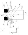
- Eine Detailansicht von
Figur 1 - Fig. 3
- Ein erstes Ausführungsbeispiel zweier Greiferpaare
- Fig. 4
- Ein zweites Ausführungsbeispiel zweier Greiferpaare
- Fig. 5
- Ein drittes Ausführungsbeispiel zweier Greiferpaare
- Fig. 6
- Eine Seitenansicht einer Greiferzange
If the active or contact surface of a first gripping means extends into the contact region of the associated second gripping means or in the vertical direction (downward) beyond this still extends, this is advantageous.
The word gripper pair indicates that sacks in such FFS machines are usually gripped and held at their two edges because a flow of filling material must be introduced into the central area of the sack. If the carrying of the bag with a plurality of contact surfaces on both sides of the Befüllgutstromes is accomplished by suitable gripping means, these gripping means are still pairs of gripper means within the meaning of the present document.
Further embodiments of the invention will become apparent from the description and the claims.
The individual figures show:
- Fig. 1
- A side view of a FFS machine
- Fig. 2
- A detail view of
FIG. 1 - Fig. 3
- A first embodiment of two gripper pairs
- Fig. 4
- A second embodiment of two gripper pairs
- Fig. 5
- A third embodiment of two gripper pairs
- Fig. 6
- A side view of a claw pliers
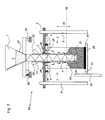
Eine Schlauchfolienbahn 15, vorzugsweise mit eingelegten Seitenfalten, wird zunächst von einem Vorzugrollensystem 9 in ein horizontal bewegliches Transportmittel, beispielsweise ein Greiferpaar 18 gefördert.
Die Folienbahn 15 wird, nachdem der Vorzug den Abschnitt entsprechend der gewünschten Sacklänge vorgezogen hat, vom Messer 17 durchgeschnitten. Gleichzeitig erfolgt die Bodenschweißung 13. Der am unteren Ende verschlossene Leersack 11 wird einem horizontal verschieblichen Transportmittel, beispielsweise einem Greifer 18, übergeben und zur Füllstation transportiert.
In der Füllstation übernimmt ein weiteres Transportmittel 4, welches aus 3,4,5 besteht, den Sackabschnitt. Der Leersack wird nun mit einem Saugersystem 16 geöffnet. Dazu wird der bzw. die Greifer 4 in Z-Richtung (sackeinwärts) bewegt. Der Anschlussstutzen des Transportsystems 3 wird in den Sack bewegt und schützt die Sackinnenflächen vor der Verschmutzung durch eventuelle Produktanhaftungen am Dosierrohr 2,21.
Der geöffnete Sack wird vom Transportsystem 3,4,5 über das Dosierrohr 2,21 gezogen, bis sich das untere Ende des Sackes ungefähr in Höhe der Füllgutaustrittsöffnung 31 befindet. Die Sackbodenunterstützungseinrichtung 32,33,34 wird bei dem gezeigten Ausführungsbeispiel unter den Sackboden gefahren. Eine Sackbodenunterstützungseinrichtung 32,33,34 ist jedoch nicht unbedingt erforderlich. Vielmehr wird die Relativbewegung des Sackes gegenüber dem Befüllorgan 2,21 hauptsächlich dadurch hervorgerufen, dass der Rahmen 5 entlang der Führung 6 fährt. Dies wird durch den Doppelpfeil 35 dargestellt. Bei diesem Ausführungsbeispiel der Erfindung wird also der Sack gegenüber dem Befüllorgan 2,21 bewegt. Denkbar ist es natürlich auch, die Relativbewegung zwischen Sack 8 und Dosierorgan durch eine Bewegung des Dosierorgans oder gar durch eine Bewegung von Sack 8 und Dosierorgan 2 herbeizuführen. In der Regel ist es hierbei ausreichend, wenn der Sack hierbei durch greiferartige Transportmittel 4 an seinem oberen Ende gehalten wird. Die erwähnte Sackbodenunterstützungseinrichtung 32,33,34 bietet optionalen, zusätzlichen Schutz vor einem Riss des gerade geschweißten Sackbodens.A
The
In the filling station takes over a
The opened bag is pulled by the
Das Verschlussrohr 21 wird angehoben und gibt die Produktaustrittsöffnung 31 frei. Das Produkt/Schüttgut 24 wird in den Sack gefüllt. Währenddessen senkt das Transportsystem 3,4,5 den Sack in der Weise ab, dass sich die Produktaustrittsöffnung 31 jederzeit unterhalb des Füllspiegels befindet. Noch vor dem Ende der Dosierung des Produktes/Schüttguts 24 kann sich die Produktaustrittsöffnung 31 jedoch zumindest einmal oberhalb des Füllspiegels 38 befinden. Nach Ende der Befüllung wird das Verschlussrohr 21 abgesenkt und verschließt die Produktaustrittsöffnung 31, indem sie Kontakt mit dem Verschluss 20 aufnimmt. Der Anschlussstutzen wird aus dem Sack gezogen. Der bzw. die Greifer 4 des Transportsystems 3,4,5 wird bzw. werden nun entgegen der Z-Richtung (sackauswärts) bewegt und zieht bzw. ziehen den Öffnungsbereich am oberen Rand 25 des zuvor geöffneten Sacks stramm. Ein weiteres Transportmittel übernimmt den befüllten Sack 8. Mittels der Verschließeinrichtung 14 wird nun der obere Rand des Sacks 25 verschlossen. Zusammen mit dem Dosiervorgang kann bei Bedarf durch den im Verschlussrohr 21 integrierten Filter abgesaugt werden. Das erforderliche Vakuum wird über den Stutzen 23 eingeleitet. Die Integration des Filters in das Verschlussrohr erlaubt eine sehr kompakte Bauform, die es ermöglicht, auch relativ kleine Säcke abzufüllen. Das Absaugen der Luft führt gewissermaßen zu einer Verdichtung des Schüttguts. Hierdurch kann eine der Produktmenge angemessene Sackgröße gewählt werden.The
Dieser Effekt der Produktverdichtung kann durch den zusätzlichen Einsatz von Vibrationserzeugern/ Klopfern 29 noch verstärkt werden. Hier ist es vorteilhaft, das Dosierrohr 2,21 mittels eines Vibrationserzeugers 29 in Schwingung zu versetzen, da es sich während der Befüllung zumindest mit Teilen seiner Mantelfläche innerhalb des Produktes befindet. Die Schwingungen werden vom Dosierrohr 2,21 an das Befüllgut 24 übertragen, in dem dann eine Verdichtung stattfindet. Ein weiterer Vorteil des "vibrierenden Dosierrohrs" 2,21 ist, dass die Bildung von Produktanhaftungen am Dosierrohr 2,21 dadurch weitgehend vermieden wird. Der Rüttler 29 könnte auch an der "Sackbodenunterstützungsvorrichtung" 34 angeordnet sein!This effect of product compaction can be enhanced by the additional use of vibration generators /
Eine besonders vorteilhafte Ausführung des Verfahrschlittens ist es, den Rahmen 5 mitsamt Stutzen 3, Transportmittel 4 sowie der Aufsaugung 16 auf Sensoren zu lagern. Die Sensoren senden ihr Signal an eine Wägeelektronik, welche letztendlich den Dosiervorgang steuert.A particularly advantageous embodiment of the carriage is to store the
Zu erwähnen ist noch die Führung bzw. Stütze 6, die den Rahmen 5 und damit die Transportmittel 4 trägt. In dem Dosierorgan beziehungsweise Rohr 2 befindet sich eine Schnecke 7, mit der Befüllmaterial 24 aus dem Trichter 1 ohne große Staubbildung in den Sack 8 gefördert werden kann. Die verschiedenen Sensoren 26 (v. a. Wägesensoren beziehungsweise Wägezellen) deuten vorteilhafte Orte zum Anbringen solcher Sensoren an. Das Transportband 27 transportiert die befüllten Säcke (8). In der Umgebung desselben sind die Kontrollwaage 30 und der Vibrationserzeuger 29 angebracht.To mention is still the guide or
Die Greifmittel 50 und 52 haben jeweils Innenkanten 55 und 56. Die Innenkanten der Greifmittel 50 des oberen Greifmittelpaares liegen in Bezug auf den Sack 8 weiter innen (= näher an der Hauptsymmetrieachse desselben) als die des unteren Greifmittelpaares 52. Zwischen dem ausgewählten Punkt 64, der in der niedrigsten Ebene des Kontaktbereiches des Greifmittels 50 und hier der Hauptsymmetrieachse Hs am nächsten liegt, und der Seitenwandung 65 des Sackes bildet sich eine Falte 59 aus. Dass die beiden Greifmittel 52 durch ihre Quetschbewegung diese Falte 59 fixieren, ist nicht optimal. Trotz der erfindungsgemäßen Ausführung der Maschine nach dem ersten Ausführungsbeispiel kann es noch zu geringfügigen Faltenbildungen kommen.
The gripping means 50 and 52 each have
In
Zwischen der Linie 66 und der Hauptsymmetrieachse sollte ein Winkel zwischen 30° und 60° liegen. Tests haben gezeigt, dass sich die Falten bevorzugt zwischen dieser Linie und der Hauptträgheitsachse Hs ausbilden.In
Between the
In
Claims (9)
dadurch gekennzeichnet, dass
zumindest ein Greifmittel (50,52) des ersten Greiferzangenpaares derart angeordnet ist, dass sich seine Innenkante (55) beim Halten des Sackes näher an der Hauptsymmetrieachse (Hs) des Sackes (8) befindet als die Innenkante (56) des Greifmittels (52) des zweiten Greifmittelpaares, das zum Ergreifen des Sackes (8) auf der gleichen Seite der Hauptsymmetrieachse (Hs) des Sackes (8) vorgesehen ist.A sack filling and closing machine comprising a first gripping means pair (50) for holding the sack (8) in the filling station (60) and a second pair of gripping means for further transporting the filled sack, the gripping means pairs being arranged to grip the sack (8) hold in its desired position on both sides of its (8) main axis of symmetry (Hs),
characterized in that
at least one gripping means (50, 52) of the first pair of gripper tongs is arranged such that its inner edge (55) is closer to the main axis of symmetry (Hs) of the bag (8) when holding the bag than the inner edge (56) of the gripping means (52) of the second pair of gripping means provided for gripping the bag (8) on the same side of the main axis of symmetry (Hs) of the bag (8).
dadurch gekennzeichnet, dass
das erste Greifmittelpaar (50) derart angeordnet ist, dass es einen Kontaktbereich mit dem Sack besitzt, der oberhalb des Kontaktbereiches des zweiten Greifmittelpaares beginnt.Machine according to claim 1,
characterized in that
the first pair of gripping means (50) is arranged such that it has a contact area with the bag, which starts above the contact area of the second pair of gripping means.
dadurch gekennzeichnet, dass
characterized in that
dadurch gekennzeichnet, dass
die Greifmittelpaare (50,52) Greiferzangenpaare sind, und dass die Zangengelenke (61) der Zangen (62) eines der beiden Greiferzangenpaare in der Befüllstation oberhalb der Position des Sackes (8) angeordnet sind, während die Zangengelenke (61) des anderen Greiferzangenpaares neben dem Sack (8) angeordnet sind.Machine according to one of the preceding claims,
characterized in that
the pairs of gripper means (50, 52) are pair of gripper pairs, and that the forceps joints (61) of the forceps (62) of one of the pair of gripper forceps are located above the position of the sack (8) in the filling station while the forceps joints (61) of the other pair of gripper arms are adjacent the bag (8) are arranged.
dadurch gekennzeichnet, dass
sich die Zangengelenke (62) des ersten Greiferzangenpaares oberhalb der Position des Sackes befinden.Machine according to the preceding claim,
characterized in that
the forceps joints (62) of the first gripper pair are above the position of the bag.
dadurch gekennzeichnet, dass
sich der Wirkbereich zumindest eines Greifmittels (50) des ersten Greifmittelpaares (50) in der senkrechten Richtung des Sackes (y) bis in den Bereich erstreckt, in dem sich der Kontaktbereich des zweiten Greifmittelpaares (52) befindet.Machine according to one of the preceding claims,
characterized in that
the effective range of at least one gripping means (50) of the first pair of gripping means (50) in the vertical direction of the bag (y) extends into the region in which the contact region of the second gripping means pair (52) is located.
dadurch gekennzeichnet, dass
sich der Wirkbereich des ersten Greifmittelpaares (50) in der senkrechten Richtung des Sackes (y) zumindest bis an das untere Ende des Kontaktbereichs des zweiten Greifmittelpaares (52) erstreckt.Machine according to the preceding claim,
characterized in that
the effective range of the first pair of gripping means (50) in the vertical direction of the bag (y) extends at least as far as the lower end of the contact area of the second pair of gripping means (52).
dadurch gekennzeichnet, dass
sich der Kontaktbereich des ersten Greifmittelpaares (50) in der senkrechten Richtung des Sackes (y) zumindest über das untere Ende des Kontaktbereichs des zweiten Greifmittelpaares hinaus erstreckt.Machine according to the preceding claim,
characterized in that
the contact area of the first pair of gripping means (50) extends in the vertical direction of the bag (y) at least beyond the lower end of the contact area of the second pair of gripping means.
dadurch gekennzeichnet, dass
characterized in that
Priority Applications (1)
| Application Number | Priority Date | Filing Date | Title |
|---|---|---|---|
| PL08004887T PL1975073T3 (en) | 2007-03-27 | 2008-03-15 | Machine for filling and closing sacks |
Applications Claiming Priority (1)
| Application Number | Priority Date | Filing Date | Title |
|---|---|---|---|
| DE102007015251A DE102007015251A1 (en) | 2007-03-27 | 2007-03-27 | Machine for filling and closing sacks |
Publications (3)
| Publication Number | Publication Date |
|---|---|
| EP1975073A2 true EP1975073A2 (en) | 2008-10-01 |
| EP1975073A3 EP1975073A3 (en) | 2014-10-15 |
| EP1975073B1 EP1975073B1 (en) | 2015-11-04 |
Family
ID=39485167
Family Applications (1)
| Application Number | Title | Priority Date | Filing Date |
|---|---|---|---|
| EP08004887.9A Not-in-force EP1975073B1 (en) | 2007-03-27 | 2008-03-15 | Machine for filling and closing sacks |
Country Status (4)
| Country | Link |
|---|---|
| EP (1) | EP1975073B1 (en) |
| DE (1) | DE102007015251A1 (en) |
| ES (1) | ES2567476T3 (en) |
| PL (1) | PL1975073T3 (en) |
Cited By (3)
| Publication number | Priority date | Publication date | Assignee | Title |
|---|---|---|---|---|
| EP3106396A3 (en) * | 2015-06-15 | 2017-01-04 | Windmöller & Hölscher KG | Packing unit and a method of packaging a product |
| FR3040376A1 (en) * | 2015-08-28 | 2017-03-03 | Cetec Ind Conditionnement | FILLING STATION WITH HIGH CADENCE BAGS, RESTRICTING DUST EMISSIONS |
| WO2018060277A1 (en) * | 2016-09-27 | 2018-04-05 | Windmöller & Hölscher Kg | Plastic bag, in particular ffs bag, and method and device for producing and filling a bag |
Families Citing this family (5)
| Publication number | Priority date | Publication date | Assignee | Title |
|---|---|---|---|---|
| DE102013105556B4 (en) * | 2013-05-29 | 2017-05-18 | Windmöller & Hölscher Kg | Clamping device for clamping a bag section of a film web in a filling station of a bag filling plant |
| DE102016123810A1 (en) * | 2016-12-08 | 2018-06-14 | Haver & Boecker Ohg | Device for filling bulk goods in open sacks |
| DE102017109495A1 (en) * | 2017-05-03 | 2018-11-08 | Haver & Boecker Ohg | Apparatus and method for filling bulk materials in open sacks |
| DE102018110637A1 (en) * | 2018-05-03 | 2019-11-07 | Haver & Boecker Ohg | Apparatus and method for filling bulk materials in open sacks |
| DE102020112991A1 (en) | 2020-05-13 | 2021-11-18 | Haver & Boecker Ohg | Packing machine and method of operation |
Citations (3)
| Publication number | Priority date | Publication date | Assignee | Title |
|---|---|---|---|---|
| DE9301355U1 (en) | 1992-10-26 | 1993-11-25 | Windmoeller & Hoelscher | Device for filling and closing bags open on one side |
| EP1459981A1 (en) | 2003-03-18 | 2004-09-22 | Concetti S.p.A. | Apparatus for filling bags with loose material and automatic machine equipped with said apparatus |
| WO2006053627A1 (en) | 2004-11-11 | 2006-05-26 | Windmöller & Hölscher Kg | Machine for forming, filling and closing bags with a bag lifting device |
Family Cites Families (5)
| Publication number | Priority date | Publication date | Assignee | Title |
|---|---|---|---|---|
| DE3118866C2 (en) * | 1981-05-13 | 1984-04-12 | Haver & Boecker, 4740 Oelde | "Machine for filling and closing plastic sacks, preferably gusseted sacks or flat sacks" |
| DE3503812C2 (en) * | 1985-02-05 | 1986-11-20 | Hans 4000 Düsseldorf Lissner | Device for attaching sacks to a filler neck |
| DE3726137A1 (en) * | 1987-08-06 | 1989-02-16 | Haver & Boecker | DEVICE FOR FILLING OPEN BAGS FROM ABOVE |
| US5768863A (en) * | 1997-03-21 | 1998-06-23 | Slidell, Inc. | Gusset control mechanism for bag closing machines |
| DE19964295C2 (en) * | 1999-05-04 | 2002-12-19 | Windmoeller & Hoelscher | Machine for producing, filling and closing plastic sacks has four pairs of tongs, filler unit, welding and cutting units |
-
2007
- 2007-03-27 DE DE102007015251A patent/DE102007015251A1/en not_active Withdrawn
-
2008
- 2008-03-15 PL PL08004887T patent/PL1975073T3/en unknown
- 2008-03-15 EP EP08004887.9A patent/EP1975073B1/en not_active Not-in-force
- 2008-03-15 ES ES08004887.9T patent/ES2567476T3/en active Active
Patent Citations (3)
| Publication number | Priority date | Publication date | Assignee | Title |
|---|---|---|---|---|
| DE9301355U1 (en) | 1992-10-26 | 1993-11-25 | Windmoeller & Hoelscher | Device for filling and closing bags open on one side |
| EP1459981A1 (en) | 2003-03-18 | 2004-09-22 | Concetti S.p.A. | Apparatus for filling bags with loose material and automatic machine equipped with said apparatus |
| WO2006053627A1 (en) | 2004-11-11 | 2006-05-26 | Windmöller & Hölscher Kg | Machine for forming, filling and closing bags with a bag lifting device |
Cited By (5)
| Publication number | Priority date | Publication date | Assignee | Title |
|---|---|---|---|---|
| EP3106396A3 (en) * | 2015-06-15 | 2017-01-04 | Windmöller & Hölscher KG | Packing unit and a method of packaging a product |
| US10301044B2 (en) | 2015-06-15 | 2019-05-28 | Windmoeller & Hoelscher Kg | Packing arrangement and method for packing a product |
| FR3040376A1 (en) * | 2015-08-28 | 2017-03-03 | Cetec Ind Conditionnement | FILLING STATION WITH HIGH CADENCE BAGS, RESTRICTING DUST EMISSIONS |
| WO2018060277A1 (en) * | 2016-09-27 | 2018-04-05 | Windmöller & Hölscher Kg | Plastic bag, in particular ffs bag, and method and device for producing and filling a bag |
| CN109996736A (en) * | 2016-09-27 | 2019-07-09 | 温德莫勒及霍尔希尔公司 | Polybag, especially FFS bags and for manufacture and for filling bag method and apparatus |
Also Published As
| Publication number | Publication date |
|---|---|
| EP1975073B1 (en) | 2015-11-04 |
| ES2567476T3 (en) | 2016-04-22 |
| PL1975073T3 (en) | 2016-04-29 |
| DE102007015251A1 (en) | 2008-10-09 |
| EP1975073A3 (en) | 2014-10-15 |
Similar Documents
| Publication | Publication Date | Title |
|---|---|---|
| EP1975073B1 (en) | Machine for filling and closing sacks | |
| EP1819596B1 (en) | Machine for forming, filling and closing bags with a bag lifting device | |
| EP3197783B1 (en) | Device and method for filling open bags | |
| DE19964295C2 (en) | Machine for producing, filling and closing plastic sacks has four pairs of tongs, filler unit, welding and cutting units | |
| EP2785594B1 (en) | Packaging machine and method for filling pouches | |
| DE2301817A1 (en) | METHOD AND DEVICE FOR THE FULLY AUTOMATIC MANUFACTURING OF FILLED SIDE GOLD BAGS MADE OF PLASTIC | |
| EP2563672B1 (en) | Method and device for producing and filling packaging means | |
| EP3755631A1 (en) | Filling device and method for filling bags with a respective unsealed upper end | |
| DE102008006410A1 (en) | Suction device for suction of air from head area of open bag filled with pasty product in buckets, has ventilation device with lance that is arranged in resting position outside bag volume and immersed into ventilation position into area | |
| DE102010029360A1 (en) | Apparatus and method for molding, filling and closing of each Ausgießeinrichtung having bags | |
| WO2018104515A1 (en) | Bag production device and method | |
| EP2008794B1 (en) | Method and device for welding bags | |
| DE19936660A1 (en) | Device for manufacturing, filling and closing bags | |
| EP3519311A1 (en) | Plastic bag, in particular ffs bag, and method and device for producing and filling a bag | |
| DE10232136A1 (en) | Sack filling machine has suction system which removes residual air from sack after filling and integral weighing system which checks that correct amount of material has been dispensed into them | |
| EP2132093B1 (en) | Machine for filling and closing bags, comprising a multifunctional sealing element | |
| EP2139772B1 (en) | Weighing method for a forming, filling and sealing machine | |
| AT406252B (en) | DEVICE FOR FILLING AND SEALING OPEN BAGS | |
| EP3826831B1 (en) | Device and method for producing at least one empty open bag | |
| EP3558828B1 (en) | Fitting device and method for fitting valve bags | |
| EP1667913B1 (en) | Method for filling sacks | |
| EP2132095B1 (en) | Device and method for forming, filling, and sealing bags | |
| WO2019158386A1 (en) | Filling device and method for filling bags with a respective unsealed upper end | |
| EP2268548B1 (en) | Device for filling bags | |
| DE102005018543A1 (en) | Handling system for e.g. bag, has guide rail system with upper and lower folding plates coupled with parts of units/products walls, and middle folding plate inserted in gusset in direction transverse to longitudinal axis of units/products |
Legal Events
| Date | Code | Title | Description |
|---|---|---|---|
| PUAI | Public reference made under article 153(3) epc to a published international application that has entered the european phase |
Free format text: ORIGINAL CODE: 0009012 |
|
| AK | Designated contracting states |
Kind code of ref document: A2 Designated state(s): AT BE BG CH CY CZ DE DK EE ES FI FR GB GR HR HU IE IS IT LI LT LU LV MC MT NL NO PL PT RO SE SI SK TR |
|
| AX | Request for extension of the european patent |
Extension state: AL BA MK RS |
|
| PUAL | Search report despatched |
Free format text: ORIGINAL CODE: 0009013 |
|
| AK | Designated contracting states |
Kind code of ref document: A3 Designated state(s): AT BE BG CH CY CZ DE DK EE ES FI FR GB GR HR HU IE IS IT LI LT LU LV MC MT NL NO PL PT RO SE SI SK TR |
|
| AX | Request for extension of the european patent |
Extension state: AL BA MK RS |
|
| RIC1 | Information provided on ipc code assigned before grant |
Ipc: B65B 43/46 20060101AFI20140908BHEP |
|
| 17P | Request for examination filed |
Effective date: 20150415 |
|
| RBV | Designated contracting states (corrected) |
Designated state(s): AT BE BG CH CY CZ DE DK EE ES FI FR GB GR HR HU IE IS IT LI LT LU LV MC MT NL NO PL PT RO SE SI SK TR |
|
| GRAP | Despatch of communication of intention to grant a patent |
Free format text: ORIGINAL CODE: EPIDOSNIGR1 |
|
| AKX | Designation fees paid |
Designated state(s): AT BE BG CH CY CZ DE DK EE ES FI FR GB GR HR HU IE IS IT LI LT LU LV MC MT NL NO PL PT RO SE SI SK TR |
|
| INTG | Intention to grant announced |
Effective date: 20150601 |
|
| GRAS | Grant fee paid |
Free format text: ORIGINAL CODE: EPIDOSNIGR3 |
|
| GRAA | (expected) grant |
Free format text: ORIGINAL CODE: 0009210 |
|
| AK | Designated contracting states |
Kind code of ref document: B1 Designated state(s): AT BE BG CH CY CZ DE DK EE ES FI FR GB GR HR HU IE IS IT LI LT LU LV MC MT NL NO PL PT RO SE SI SK TR |
|
| REG | Reference to a national code |
Ref country code: GB Ref legal event code: FG4D Free format text: NOT ENGLISH |
|
| REG | Reference to a national code |
Ref country code: CH Ref legal event code: EP |
|
| REG | Reference to a national code |
Ref country code: AT Ref legal event code: REF Ref document number: 759002 Country of ref document: AT Kind code of ref document: T Effective date: 20151115 |
|
| REG | Reference to a national code |
Ref country code: IE Ref legal event code: FG4D Free format text: LANGUAGE OF EP DOCUMENT: GERMAN |
|
| REG | Reference to a national code |
Ref country code: DE Ref legal event code: R096 Ref document number: 502008013534 Country of ref document: DE |
|
| REG | Reference to a national code |
Ref country code: LT Ref legal event code: MG4D |
|
| REG | Reference to a national code |
Ref country code: NL Ref legal event code: FP |
|
| REG | Reference to a national code |
Ref country code: ES Ref legal event code: FG2A Ref document number: 2567476 Country of ref document: ES Kind code of ref document: T3 Effective date: 20160422 |
|
| PG25 | Lapsed in a contracting state [announced via postgrant information from national office to epo] |
Ref country code: LT Free format text: LAPSE BECAUSE OF FAILURE TO SUBMIT A TRANSLATION OF THE DESCRIPTION OR TO PAY THE FEE WITHIN THE PRESCRIBED TIME-LIMIT Effective date: 20151104 Ref country code: HR Free format text: LAPSE BECAUSE OF FAILURE TO SUBMIT A TRANSLATION OF THE DESCRIPTION OR TO PAY THE FEE WITHIN THE PRESCRIBED TIME-LIMIT Effective date: 20151104 Ref country code: IS Free format text: LAPSE BECAUSE OF FAILURE TO SUBMIT A TRANSLATION OF THE DESCRIPTION OR TO PAY THE FEE WITHIN THE PRESCRIBED TIME-LIMIT Effective date: 20160304 Ref country code: NO Free format text: LAPSE BECAUSE OF FAILURE TO SUBMIT A TRANSLATION OF THE DESCRIPTION OR TO PAY THE FEE WITHIN THE PRESCRIBED TIME-LIMIT Effective date: 20160204 |
|
| PG25 | Lapsed in a contracting state [announced via postgrant information from national office to epo] |
Ref country code: GR Free format text: LAPSE BECAUSE OF FAILURE TO SUBMIT A TRANSLATION OF THE DESCRIPTION OR TO PAY THE FEE WITHIN THE PRESCRIBED TIME-LIMIT Effective date: 20160205 Ref country code: LV Free format text: LAPSE BECAUSE OF FAILURE TO SUBMIT A TRANSLATION OF THE DESCRIPTION OR TO PAY THE FEE WITHIN THE PRESCRIBED TIME-LIMIT Effective date: 20151104 Ref country code: FI Free format text: LAPSE BECAUSE OF FAILURE TO SUBMIT A TRANSLATION OF THE DESCRIPTION OR TO PAY THE FEE WITHIN THE PRESCRIBED TIME-LIMIT Effective date: 20151104 Ref country code: PT Free format text: LAPSE BECAUSE OF FAILURE TO SUBMIT A TRANSLATION OF THE DESCRIPTION OR TO PAY THE FEE WITHIN THE PRESCRIBED TIME-LIMIT Effective date: 20160304 Ref country code: SE Free format text: LAPSE BECAUSE OF FAILURE TO SUBMIT A TRANSLATION OF THE DESCRIPTION OR TO PAY THE FEE WITHIN THE PRESCRIBED TIME-LIMIT Effective date: 20151104 |
|
| PG25 | Lapsed in a contracting state [announced via postgrant information from national office to epo] |
Ref country code: CZ Free format text: LAPSE BECAUSE OF FAILURE TO SUBMIT A TRANSLATION OF THE DESCRIPTION OR TO PAY THE FEE WITHIN THE PRESCRIBED TIME-LIMIT Effective date: 20151104 |
|
| REG | Reference to a national code |
Ref country code: DE Ref legal event code: R097 Ref document number: 502008013534 Country of ref document: DE |
|
| PG25 | Lapsed in a contracting state [announced via postgrant information from national office to epo] |
Ref country code: RO Free format text: LAPSE BECAUSE OF FAILURE TO SUBMIT A TRANSLATION OF THE DESCRIPTION OR TO PAY THE FEE WITHIN THE PRESCRIBED TIME-LIMIT Effective date: 20151104 Ref country code: SK Free format text: LAPSE BECAUSE OF FAILURE TO SUBMIT A TRANSLATION OF THE DESCRIPTION OR TO PAY THE FEE WITHIN THE PRESCRIBED TIME-LIMIT Effective date: 20151104 Ref country code: DK Free format text: LAPSE BECAUSE OF FAILURE TO SUBMIT A TRANSLATION OF THE DESCRIPTION OR TO PAY THE FEE WITHIN THE PRESCRIBED TIME-LIMIT Effective date: 20151104 Ref country code: EE Free format text: LAPSE BECAUSE OF FAILURE TO SUBMIT A TRANSLATION OF THE DESCRIPTION OR TO PAY THE FEE WITHIN THE PRESCRIBED TIME-LIMIT Effective date: 20151104 |
|
| PLBE | No opposition filed within time limit |
Free format text: ORIGINAL CODE: 0009261 |
|
| STAA | Information on the status of an ep patent application or granted ep patent |
Free format text: STATUS: NO OPPOSITION FILED WITHIN TIME LIMIT |
|
| 26N | No opposition filed |
Effective date: 20160805 |
|
| PG25 | Lapsed in a contracting state [announced via postgrant information from national office to epo] |
Ref country code: LU Free format text: LAPSE BECAUSE OF FAILURE TO SUBMIT A TRANSLATION OF THE DESCRIPTION OR TO PAY THE FEE WITHIN THE PRESCRIBED TIME-LIMIT Effective date: 20160315 Ref country code: MC Free format text: LAPSE BECAUSE OF FAILURE TO SUBMIT A TRANSLATION OF THE DESCRIPTION OR TO PAY THE FEE WITHIN THE PRESCRIBED TIME-LIMIT Effective date: 20151104 |
|
| REG | Reference to a national code |
Ref country code: CH Ref legal event code: PL |
|
| GBPC | Gb: european patent ceased through non-payment of renewal fee |
Effective date: 20160315 |
|
| PG25 | Lapsed in a contracting state [announced via postgrant information from national office to epo] |
Ref country code: SI Free format text: LAPSE BECAUSE OF FAILURE TO SUBMIT A TRANSLATION OF THE DESCRIPTION OR TO PAY THE FEE WITHIN THE PRESCRIBED TIME-LIMIT Effective date: 20151104 |
|
| REG | Reference to a national code |
Ref country code: IE Ref legal event code: MM4A |
|
| REG | Reference to a national code |
Ref country code: FR Ref legal event code: ST Effective date: 20161130 |
|
| PG25 | Lapsed in a contracting state [announced via postgrant information from national office to epo] |
Ref country code: CH Free format text: LAPSE BECAUSE OF NON-PAYMENT OF DUE FEES Effective date: 20160331 Ref country code: LI Free format text: LAPSE BECAUSE OF NON-PAYMENT OF DUE FEES Effective date: 20160331 Ref country code: FR Free format text: LAPSE BECAUSE OF NON-PAYMENT OF DUE FEES Effective date: 20160331 Ref country code: IE Free format text: LAPSE BECAUSE OF NON-PAYMENT OF DUE FEES Effective date: 20160315 Ref country code: GB Free format text: LAPSE BECAUSE OF NON-PAYMENT OF DUE FEES Effective date: 20160315 |
|
| PG25 | Lapsed in a contracting state [announced via postgrant information from national office to epo] |
Ref country code: IT Free format text: LAPSE BECAUSE OF NON-PAYMENT OF DUE FEES Effective date: 20160315 |
|
| PG25 | Lapsed in a contracting state [announced via postgrant information from national office to epo] |
Ref country code: IT Free format text: LAPSE BECAUSE OF NON-PAYMENT OF DUE FEES Effective date: 20160315 Ref country code: MT Free format text: LAPSE BECAUSE OF FAILURE TO SUBMIT A TRANSLATION OF THE DESCRIPTION OR TO PAY THE FEE WITHIN THE PRESCRIBED TIME-LIMIT Effective date: 20151104 |
|
| PGRI | Patent reinstated in contracting state [announced from national office to epo] |
Ref country code: IT Effective date: 20170710 |
|
| PG25 | Lapsed in a contracting state [announced via postgrant information from national office to epo] |
Ref country code: CY Free format text: LAPSE BECAUSE OF FAILURE TO SUBMIT A TRANSLATION OF THE DESCRIPTION OR TO PAY THE FEE WITHIN THE PRESCRIBED TIME-LIMIT Effective date: 20151104 Ref country code: HU Free format text: LAPSE BECAUSE OF FAILURE TO SUBMIT A TRANSLATION OF THE DESCRIPTION OR TO PAY THE FEE WITHIN THE PRESCRIBED TIME-LIMIT; INVALID AB INITIO Effective date: 20080315 |
|
| PG25 | Lapsed in a contracting state [announced via postgrant information from national office to epo] |
Ref country code: TR Free format text: LAPSE BECAUSE OF FAILURE TO SUBMIT A TRANSLATION OF THE DESCRIPTION OR TO PAY THE FEE WITHIN THE PRESCRIBED TIME-LIMIT Effective date: 20151104 |
|
| PG25 | Lapsed in a contracting state [announced via postgrant information from national office to epo] |
Ref country code: BG Free format text: LAPSE BECAUSE OF FAILURE TO SUBMIT A TRANSLATION OF THE DESCRIPTION OR TO PAY THE FEE WITHIN THE PRESCRIBED TIME-LIMIT Effective date: 20151104 |
|
| PGFP | Annual fee paid to national office [announced via postgrant information from national office to epo] |
Ref country code: GB Payment date: 20190308 Year of fee payment: 12 Ref country code: IT Payment date: 20190321 Year of fee payment: 12 |
|
| PGFP | Annual fee paid to national office [announced via postgrant information from national office to epo] |
Ref country code: AT Payment date: 20190328 Year of fee payment: 12 Ref country code: NL Payment date: 20190325 Year of fee payment: 12 |
|
| PGFP | Annual fee paid to national office [announced via postgrant information from national office to epo] |
Ref country code: ES Payment date: 20190425 Year of fee payment: 12 |
|
| PGFP | Annual fee paid to national office [announced via postgrant information from national office to epo] |
Ref country code: BE Payment date: 20190328 Year of fee payment: 12 |
|
| PGFP | Annual fee paid to national office [announced via postgrant information from national office to epo] |
Ref country code: PL Payment date: 20200306 Year of fee payment: 13 |
|
| REG | Reference to a national code |
Ref country code: DE Ref legal event code: R119 Ref document number: 502008013534 Country of ref document: DE |
|
| REG | Reference to a national code |
Ref country code: NL Ref legal event code: MM Effective date: 20200401 |
|
| REG | Reference to a national code |
Ref country code: AT Ref legal event code: MM01 Ref document number: 759002 Country of ref document: AT Kind code of ref document: T Effective date: 20200315 |
|
| REG | Reference to a national code |
Ref country code: BE Ref legal event code: MM Effective date: 20200331 |
|
| PG25 | Lapsed in a contracting state [announced via postgrant information from national office to epo] |
Ref country code: NL Free format text: LAPSE BECAUSE OF NON-PAYMENT OF DUE FEES Effective date: 20200401 |
|
| PG25 | Lapsed in a contracting state [announced via postgrant information from national office to epo] |
Ref country code: DE Free format text: LAPSE BECAUSE OF NON-PAYMENT OF DUE FEES Effective date: 20201001 Ref country code: AT Free format text: LAPSE BECAUSE OF NON-PAYMENT OF DUE FEES Effective date: 20200315 |
|
| PG25 | Lapsed in a contracting state [announced via postgrant information from national office to epo] |
Ref country code: BE Free format text: LAPSE BECAUSE OF NON-PAYMENT OF DUE FEES Effective date: 20200331 |
|
| REG | Reference to a national code |
Ref country code: ES Ref legal event code: FD2A Effective date: 20210802 |
|
| PG25 | Lapsed in a contracting state [announced via postgrant information from national office to epo] |
Ref country code: ES Free format text: LAPSE BECAUSE OF NON-PAYMENT OF DUE FEES Effective date: 20200316 |
|
| PG25 | Lapsed in a contracting state [announced via postgrant information from national office to epo] |
Ref country code: PL Free format text: LAPSE BECAUSE OF NON-PAYMENT OF DUE FEES Effective date: 20210315 |
|
| PG25 | Lapsed in a contracting state [announced via postgrant information from national office to epo] |
Ref country code: IT Free format text: LAPSE BECAUSE OF NON-PAYMENT OF DUE FEES Effective date: 20200315 |