EP1974195B1 - Pressure sensor with deflectable diaphragm - Google Patents
Pressure sensor with deflectable diaphragm Download PDFInfo
- Publication number
- EP1974195B1 EP1974195B1 EP06844974.3A EP06844974A EP1974195B1 EP 1974195 B1 EP1974195 B1 EP 1974195B1 EP 06844974 A EP06844974 A EP 06844974A EP 1974195 B1 EP1974195 B1 EP 1974195B1
- Authority
- EP
- European Patent Office
- Prior art keywords
- diaphragm
- pressure
- sensor
- pressure sensor
- cavity
- Prior art date
- Legal status (The legal status is an assumption and is not a legal conclusion. Google has not performed a legal analysis and makes no representation as to the accuracy of the status listed.)
- Active
Links
- 238000000034 method Methods 0.000 claims description 44
- 230000008569 process Effects 0.000 claims description 28
- 239000003990 capacitor Substances 0.000 claims description 25
- 239000012530 fluid Substances 0.000 claims description 15
- 239000002184 metal Substances 0.000 claims description 10
- 239000000463 material Substances 0.000 claims description 8
- 230000004044 response Effects 0.000 claims description 6
- 239000013078 crystal Substances 0.000 claims description 2
- 239000010453 quartz Substances 0.000 claims description 2
- 229910052594 sapphire Inorganic materials 0.000 claims description 2
- 239000010980 sapphire Substances 0.000 claims description 2
- 229910052710 silicon Inorganic materials 0.000 claims description 2
- 239000010703 silicon Substances 0.000 claims description 2
- VYPSYNLAJGMNEJ-UHFFFAOYSA-N silicon dioxide Inorganic materials O=[Si]=O VYPSYNLAJGMNEJ-UHFFFAOYSA-N 0.000 claims description 2
- 239000011029 spinel Substances 0.000 claims description 2
- 229910052596 spinel Inorganic materials 0.000 claims description 2
- 238000005259 measurement Methods 0.000 description 9
- 230000006854 communication Effects 0.000 description 7
- 238000004891 communication Methods 0.000 description 7
- 238000004519 manufacturing process Methods 0.000 description 7
- 238000009530 blood pressure measurement Methods 0.000 description 5
- 239000007787 solid Substances 0.000 description 5
- 239000011521 glass Substances 0.000 description 4
- 230000006870 function Effects 0.000 description 3
- 239000012528 membrane Substances 0.000 description 3
- 238000005219 brazing Methods 0.000 description 2
- 239000004020 conductor Substances 0.000 description 2
- 238000012369 In process control Methods 0.000 description 1
- 239000000654 additive Substances 0.000 description 1
- 230000000996 additive effect Effects 0.000 description 1
- 238000005452 bending Methods 0.000 description 1
- 230000007175 bidirectional communication Effects 0.000 description 1
- 230000005540 biological transmission Effects 0.000 description 1
- 230000008859 change Effects 0.000 description 1
- 230000002596 correlated effect Effects 0.000 description 1
- 230000001419 dependent effect Effects 0.000 description 1
- 238000010586 diagram Methods 0.000 description 1
- 238000010965 in-process control Methods 0.000 description 1
- 238000010978 in-process monitoring Methods 0.000 description 1
- 239000011810 insulating material Substances 0.000 description 1
- 238000002955 isolation Methods 0.000 description 1
- 239000007788 liquid Substances 0.000 description 1
- 239000012811 non-conductive material Substances 0.000 description 1
- 239000003921 oil Substances 0.000 description 1
- 238000003466 welding Methods 0.000 description 1
Images


Classifications
-
- G—PHYSICS
- G01—MEASURING; TESTING
- G01L—MEASURING FORCE, STRESS, TORQUE, WORK, MECHANICAL POWER, MECHANICAL EFFICIENCY, OR FLUID PRESSURE
- G01L9/00—Measuring steady of quasi-steady pressure of fluid or fluent solid material by electric or magnetic pressure-sensitive elements; Transmitting or indicating the displacement of mechanical pressure-sensitive elements, used to measure the steady or quasi-steady pressure of a fluid or fluent solid material, by electric or magnetic means
- G01L9/0041—Transmitting or indicating the displacement of flexible diaphragms
- G01L9/0072—Transmitting or indicating the displacement of flexible diaphragms using variations in capacitance
- G01L9/0075—Transmitting or indicating the displacement of flexible diaphragms using variations in capacitance using a ceramic diaphragm, e.g. alumina, fused quartz, glass
-
- G—PHYSICS
- G01—MEASURING; TESTING
- G01L—MEASURING FORCE, STRESS, TORQUE, WORK, MECHANICAL POWER, MECHANICAL EFFICIENCY, OR FLUID PRESSURE
- G01L13/00—Devices or apparatus for measuring differences of two or more fluid pressure values
- G01L13/02—Devices or apparatus for measuring differences of two or more fluid pressure values using elastically-deformable members or pistons as sensing elements
- G01L13/025—Devices or apparatus for measuring differences of two or more fluid pressure values using elastically-deformable members or pistons as sensing elements using diaphragms
Definitions
- the present invention relates to pressure sensors. More specifically, the present invention relates to pressure sensors of the type which use a deflectable diaphragm to measure a pressure.
- Transmitters are used in process monitoring and control systems to measure various process variables of industrial processes.
- One type of transmitter measures pressure of process fluid in the process.
- Various techniques have been used in the pressure sensors used in such transmitters.
- One well known technique is to use a deflectable metal diaphragm. A capacitance is measured with respect to the diaphragm, with the metal diaphragm forming one of the capacitive plates of the capacitor. As the diaphragm is deflected due to applied pressure, the measured capacitance changes. In such a configuration, there are a number of sources of inaccuracies in pressure measurements.
- DE 100 52 053 A1 describes a pressure measuring cell comprising a base body and a membrane that is connected to the base body.
- the cell also comprises a membrane bed, formed by a surface of the base body that faces the membrane.
- US 4 458 537 A describes a capacitive pressure transducer in which a sensing diaphragm bearing an electrode is mounted to flex in response to applied fluid pressure relative to a reference member having an opposed electrode
- US 2002/0178827 A1 describes a pressure transmitter that includes a pressure sensor comprising a pressure cell having an interior to form a main cell cavity and a deflectable diaphragm which deflects in response to an applied pressure.
- US 4 172 387 A describes a liquid filled differential pressure transmitter that includes a metallic measurement diaphragm within a pressure chamber.
- WO 88/00335 A1 describes a cell for sensing differential pressures that has a single brittle material diaphragm mounted on support plates positioned on opposite sides of the diaphragm.
- the present invention provides a pressure sensor in which a deflectable diaphragm carries a capacitive plate to provide a capacitance which varies in response to an applied pressure. As discussed below, this configuration provides a number of advantages related to manufacturing, reduced errors and improved performance.
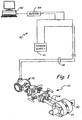
- Figure 1 shows generally the environment of a process measurement system 32.
- Figure 1 shows process piping 30 containing a fluid under pressure coupled to the process measurement system 32 for measuring a process pressure.
- the process measurement system 32 includes impulse piping 34 connected to the piping 30.
- the impulse piping 34 is connected to a process pressure transmitter 36.
- a primary element 33 such as an orifice plate, venturi tube, flow nozzle, and so on, contacts the process fluid at a location in the process piping 30 between the pipes of the impulse piping 34.
- the primary element 33 causes a pressure change in the fluid as it passes past the primary element 33.
- Transmitter 36 is a process measurement device that receives process pressures through the impulse piping 34.
- the transmitter 36 senses a differential process pressure and outputs a standardized transmission signal that is a function of the process pressure.
- a process loop 38 provides both a power signal to the transmitter 36 from control room 40 and bidirectional communication, and can be constructed in accordance with a number of process communication protocols.
- the process loop 38 is a two-wire loop.
- the two-wire loop is used to transmit all power to and all communications to and from the transmitter 36 during normal operations with a 4-20 mA signal.
- a computer 42 or other information handling system through modem 44, or other network interface, is used for communication with the transmitter 36.
- a remote voltage power supply 46 powers the transmitter 36.
- the invention is not limited to environments which implement a loop 38.
- Other communication techniques can be used including other communication media such as wireless and different wireless techniques, as well as different communication protocols and in standalone devices.
- FIG. 2 is a simplified block diagram of pressure transmitter 36.
- Pressure transmitter 36 includes a sensor module 52 and an electronics board 72 coupled together through a databus 66.
- Sensor module electronics 60 couples to pressure sensor 56 which received an applied differential pressure 54.
- the data connection 58 couples sensor 56 to an analog to digital converter 62.
- An optional temperature sensor 63 is also illustrated along with sensor module memory 64. As discussed below, the temperature sensor 63 can be formed integral with pressure sensor 56.
- the electronics board 72 includes a microcomputer system 74, electronics memory module 76, digital to analog signal converter 78 and digital communication block 80.
- FIG. 3A is a side cross-sectional view showing pressure sensor 56 in accordance with the present invention.
- Pressure sensor 56 includes a pressure sensor body 140 which is formed by half bodies 142 and 144 which have recessed regions 146 and 148 formed therein, respectively, which form a cavity 149 therebetween.
- a deflectable diaphragm 150 is mounted in the cavity 149 and the cavity 149 couples to impulse piping 94.
- Diaphragm 150 is formed of two half diaphragms 152 and 154. Center capacitor plates or electrodes 162 and 164 are carried on diaphragm halves 152 and 154, respectively.
- diaphragm half 152 carries outer capacitor plate or electrode 166 while diaphragm half 154 carries outer capacitor plate or electrode 172.
- a contact protrusion 180 extends from center diaphragm 150 and carries electrical contacts 182 thereon. Electrical contacts 182 connects to each of the six capacitor plates or electrodes 162 through 172.
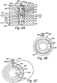
- Figure 3B is a front plan view showing deflectable diaphragm 150 including the arrangement of capacitor plates 162 and 166 in greater detail.
- Figure 3C is a side perspective view showing half diaphragm 154 and half sensor body 144.
- Figure 3C also illustrates electrical connections 192 and 196 which electrically connect capacitor plates or electrodes 170 and 164, respectively, to contacts 182 on protrusion 180.
- Figures 3A and 3B also show annular notches 200 which can be formed in the diaphragm 150 to increase the amount of deflection of diaphragm 150 for a given pressure.
- a differential pressure is applied to either side of diaphragm 154 through impulse piping 94.
- This causes deflection of diaphragm 150 within cavity 149.
- the distance between capacitor plates 162, 164, 166, 168, 170, 172 changes with respect to the sides of cavity 149 formed by sensor body halves 142 and 144.
- the electrical capacitance between each capacitor plate 162, 164, 166, 168, 170, 172 can be measured with respect to the sensor body 140 and correlated with the applied differential pressure.
- the amount of deflection of diaphragm 154 is a function of the applied pressure as well as the material used in diaphragm 154 and the dimensions of diaphragm 154.
- Figures 3A through 3B also show annular notches 200 which can be formed in the diaphragm 150 to increase the amount of deflection of diaphragm 150 for a given pressure.
- diaphragm 150 is formed of an insulating crystal material such as silicon, quartz, sapphire, or spinel.
- the electrodes can comprise a metal and be deposited or implanted on diaphragm 150.
- the sensor body 140 is formed of a conductive material such as metal. This configuration allows the diaphragm 150 to be assembled and subsequently mounted into body halves 142 and 144.
- body 140 is of a nonconductive material and include a conductive material for the electrical capacitors with respect to capacitor plates 162, 164, 166, 168, 170, 172.
- some prior art configurations in which the capacitor plates are carried on the walls of the cavity formed in the sensor body. This requires the sensor body to be filled with an insulating material such as glass. In such a configuration, a conductive diaphragm used.
- features 177 are provided on an internal wall of cavity 146 or on diaphragm 150.
- Features 177 are configured to distribute forces if an over pressure occurs in which diaphragm 150 is pressed against one of the internal walls of cavity 146.
- the pressure sensor 56 of the present invention can be assembled using any appropriate technique.
- the two diaphragm halves 152 and 154 can be fused together to form the complete diaphragm 150. Additional features such as the diaphragm shape and hinge point can be fabricated as desired.
- a temperature sensor 210 is fabricated in diaphragm 150 for use in measuring temperature of the pressure sensor 56. The temperature can be used to compensate for temperature related errors in pressure measurements. The temperature signal can also be used to determine other information about the process fluid, such as for use in a flow rate calculation.
- the completed diaphragm 150 is welded between the two metal sensor body halves 142 and 144 with protrusion 180 extending from the cavity 149 through the sensor body 140 to the outside of body 140.
- the region where protrusion 180 meets the two sensor half bodies 142 and 144 can be sealed using, for example, a brazing technique.
- This configuration provides a solid state sensor with electrodes that can be mounted on a solid state material rather than a glass such as used in some prior art configurations. This reduces hysteresis and provides improved stability. Further, the capacitor electrodes on the high and low pressure sides of the diaphragm 150 remain in close proximity which can also provide improved performance over temperature extremes.
- the center diaphragm 150 can be fabricated using standard solid state fabrication techniques which allow simplified manufacturing, reduced costs and greater tolerance control. Sensor features such as the hinge point, cavity shape, electrodes, electrode lead wires and temperature sensor are etched, deposited or otherwise formed in a solid state center diaphragm structure rather than on a glass/metal pressure sensor half cell as used in prior art designs. This simplifies manufacturing, lowers manufacturing cost and provides greater tolerance control which leads to improved performance.
- an optional internal cavity 220 is illustrated which is located within diaphragm 154 between diaphragm halves 150 and 152.
- Capacitive plates or electrodes 222 and 224 are positioned on the sides walls of internal cavity 220.
- Internal cavity 220 is configured such that the spacing between capacitive plates 222 and 224 changes as a function of the applied line pressure.
- This optional configuration allows both the differential pressure applied to diaphragm 150 through impulse piping 94 to be measured along with the line pressure.
- electrical contacts are provided on and protrusion 180 which connect to capacitor plates or electrodes 222 and 224.
- FIG 4 is a simplified cross-sectional view of one embodiment of a sensor module 52 showing pressure sensor 56.
- Pressure sensor 56 couples to a process fluid through isolation diaphragms 90 which isolate the process fluid from cavities 92. Cavities 92 couple to the pressure sensor module 56 through impulse piping 94.
- a substantially incompressible fill fluid fills cavities 92 and impulse piping 94. When a pressure from the process fluid is applied to diaphragms 90, the pressure is transferred to the pressure sensor 56 through the fill fluid in the impulse piping 94.
- features such as the hinge point, cavity shape, electrodes, electrode lead wires and the temperature sensor can be etched, deposited or otherwise formed in a solid state structure rather than in the glass/metal half cell used in some designs. This reduces manufacturing costs and provides greater tolerance control which allows improved. performance.
- the outside of the pressure sensor is formed of a metal body which can easily contain excessive over pressures.
- the structure can be formed and mounted using any appropriate technique such as laser welding or brazing.
- the measurement circuitry used to determine the applied pressure based upon the changing capacitance can be mounted in close proximity to the protrusion 180. This to reduces errors due to stray capacitance from the electrical connections to the capacitor plates. In some configurations, the circuitry is carried directly on protrusion 180. In such a configuration, measurement circuitry can be mounted to protrusion 180, or fabricated directly on protrusion 180.
- Pressure measurements may be made using the pressure sensor discussed above using any appropriate technique.
- One example technique is described in U.S. Patent application Serial No. 11/140,681 , Line Pressure Measurement Using Differential Pressure Sensor, filed May 27, 2005 which is incorporated herein by reference.
- the particular configuration illustrated in the Figures in which four different capacitors are formed can be used to compensate for errors as discussed in application Serial No. 11/140,681 .
- any number of capacitors are used including a single capacitor, two capacitors, etc.
- the present invention is not limited to any particular number of capacitors or configuration of capacitor plates.
- the diaphragm can be configured to deflect as desired. In one configuration, the diaphragm deflection may be less than one angstrom.
- the center diaphragm structure can have any shape and/or feature as desired for particular implementation.
- the diaphragm can have hinge features to promote bending at certain points, ceiling features, etc. This allows the diaphragm to be optimized for performance of the sensor in a particular environment, such as a differential pressure sensor.
- These features and shapes can be formed using any appropriate method including both additive techniques in which additional structures are added to a sub straight, or subtractive techniques in which material is removed from a sub straight to form a desired shape or feature.
Landscapes
- Physics & Mathematics (AREA)
- General Physics & Mathematics (AREA)
- Chemical & Material Sciences (AREA)
- Engineering & Computer Science (AREA)
- Ceramic Engineering (AREA)
- Measuring Fluid Pressure (AREA)
Description
- The present invention relates to pressure sensors. More specifically, the present invention relates to pressure sensors of the type which use a deflectable diaphragm to measure a pressure.
- Transmitters are used in process monitoring and control systems to measure various process variables of industrial processes. One type of transmitter measures pressure of process fluid in the process. Various techniques have been used in the pressure sensors used in such transmitters. One well known technique is to use a deflectable metal diaphragm. A capacitance is measured with respect to the diaphragm, with the metal diaphragm forming one of the capacitive plates of the capacitor. As the diaphragm is deflected due to applied pressure, the measured capacitance changes. In such a configuration, there are a number of sources of inaccuracies in pressure measurements.
- One technique which addresses these inaccuracies is set forth in
U.S. Patent No. 6,295,875 entitled, "PROCESS PRESSURE MEASUREMENT DEVICES WITH IMPROVED ERROR COMPENSATION" issued October 2, 2001 to Frick et al. which is incorporated herein by reference in its entirety. This patent describes a differential pressure sensor that includes an additional electrode for use in reducing measurement inaccuracies. -
DE 100 52 053 A1 describes a pressure measuring cell comprising a base body and a membrane that is connected to the base body. The cell also comprises a membrane bed, formed by a surface of the base body that faces the membrane. -
US 4 458 537 A describes a capacitive pressure transducer in which a sensing diaphragm bearing an electrode is mounted to flex in response to applied fluid pressure relative to a reference member having an opposed electrode -
US 2002/0178827 A1 describes a pressure transmitter that includes a pressure sensor comprising a pressure cell having an interior to form a main cell cavity and a deflectable diaphragm which deflects in response to an applied pressure. -
US 4 172 387 A describes a liquid filled differential pressure transmitter that includes a metallic measurement diaphragm within a pressure chamber. -
WO 88/00335 A1 -
DE 101 17 142 A1 describes a further differential pressure sensor. - The present invention is defined in claims 1 and 13. Further embodiments are defined in the dependent claims.
-
-
Figure 1 shows a process measurement system with a process transmitter constructed in accordance with the present invention. -
Figure 2 is schematic view of a transmitter ofFigure 1 . -
Figure 3A is a side cross-sectional view of a pressure sensor in accordance with the present invention. -
Figure 3B is a front plan view of a diaphragm of the pressure sensor shown inFIG. 3A . -
Figure 3C is a perspective view showing half of the diaphragm offigure 3A and half of a sensor body offigure 3A . -
Figure 4 is a simplified cross-sectional view of the pressure sensor positioned in a process transmitter. - The present invention provides a pressure sensor in which a deflectable diaphragm carries a capacitive plate to provide a capacitance which varies in response to an applied pressure. As discussed below, this configuration provides a number of advantages related to manufacturing, reduced errors and improved performance.
-
Figure 1 shows generally the environment of aprocess measurement system 32.Figure 1 showsprocess piping 30 containing a fluid under pressure coupled to theprocess measurement system 32 for measuring a process pressure. Theprocess measurement system 32 includesimpulse piping 34 connected to thepiping 30. Theimpulse piping 34 is connected to aprocess pressure transmitter 36. Aprimary element 33, such as an orifice plate, venturi tube, flow nozzle, and so on, contacts the process fluid at a location in the process piping 30 between the pipes of theimpulse piping 34. Theprimary element 33 causes a pressure change in the fluid as it passes past theprimary element 33. -
Transmitter 36 is a process measurement device that receives process pressures through theimpulse piping 34. Thetransmitter 36 senses a differential process pressure and outputs a standardized transmission signal that is a function of the process pressure. - A
process loop 38 provides both a power signal to thetransmitter 36 from control room 40 and bidirectional communication, and can be constructed in accordance with a number of process communication protocols. In the illustrated example, theprocess loop 38 is a two-wire loop. The two-wire loop is used to transmit all power to and all communications to and from thetransmitter 36 during normal operations with a 4-20 mA signal. Acomputer 42 or other information handling system throughmodem 44, or other network interface, is used for communication with thetransmitter 36. A remotevoltage power supply 46 powers thetransmitter 36. The invention is not limited to environments which implement aloop 38. Other communication techniques can be used including other communication media such as wireless and different wireless techniques, as well as different communication protocols and in standalone devices. -
Figure 2 is a simplified block diagram ofpressure transmitter 36.Pressure transmitter 36 includes asensor module 52 and anelectronics board 72 coupled together through adatabus 66.Sensor module electronics 60 couples topressure sensor 56 which received an applieddifferential pressure 54. Thedata connection 58couples sensor 56 to an analog todigital converter 62. Anoptional temperature sensor 63 is also illustrated along withsensor module memory 64. As discussed below, thetemperature sensor 63 can be formed integral withpressure sensor 56. Theelectronics board 72 includes amicrocomputer system 74,electronics memory module 76, digital toanalog signal converter 78 anddigital communication block 80. - One technique for measuring different pressure is set forth in
U.S. Patent No. 6,295,875 to Frick et al. However, the present invention is not limited to such a configuration. -
Figure 3A is a side cross-sectional view showingpressure sensor 56 in accordance with the present invention.Pressure sensor 56 includes apressure sensor body 140 which is formed byhalf bodies recessed regions 146 and 148 formed therein, respectively, which form acavity 149 therebetween. Adeflectable diaphragm 150 is mounted in thecavity 149 and thecavity 149 couples to impulsepiping 94.Diaphragm 150 is formed of twohalf diaphragms electrodes diaphragm halves electrode 166 whilediaphragm half 154 carries outer capacitor plate orelectrode 172.Capacitor plates sensor body 140. Acontact protrusion 180 extends fromcenter diaphragm 150 and carrieselectrical contacts 182 thereon.Electrical contacts 182 connects to each of the six capacitor plates orelectrodes 162 through 172. -
Figure 3B is a front plan view showingdeflectable diaphragm 150 including the arrangement ofcapacitor plates Figure 3C is a side perspective view showinghalf diaphragm 154 andhalf sensor body 144.Figure 3C also illustrateselectrical connections 192 and 196 which electrically connect capacitor plates orelectrodes contacts 182 onprotrusion 180.Figures 3A and 3B also showannular notches 200 which can be formed in thediaphragm 150 to increase the amount of deflection ofdiaphragm 150 for a given pressure. - During operation, a differential pressure is applied to either side of
diaphragm 154 through impulse piping 94. This causes deflection ofdiaphragm 150 withincavity 149. Asdiaphragm 150 deflects, the distance betweencapacitor plates cavity 149 formed by sensor body halves 142 and 144. The electrical capacitance between eachcapacitor plate sensor body 140 and correlated with the applied differential pressure. The amount of deflection ofdiaphragm 154 is a function of the applied pressure as well as the material used indiaphragm 154 and the dimensions ofdiaphragm 154.Figures 3A through 3B also showannular notches 200 which can be formed in thediaphragm 150 to increase the amount of deflection ofdiaphragm 150 for a given pressure. - In one preferred configuration,
diaphragm 150 is formed of an insulating crystal material such as silicon, quartz, sapphire, or spinel. The electrodes can comprise a metal and be deposited or implanted ondiaphragm 150. Thesensor body 140 is formed of a conductive material such as metal. This configuration allows thediaphragm 150 to be assembled and subsequently mounted intobody halves body 140 is of a nonconductive material and include a conductive material for the electrical capacitors with respect tocapacitor plates - In one optional configuration, features 177 are provided on an internal wall of
cavity 146 or ondiaphragm 150.Features 177 are configured to distribute forces if an over pressure occurs in which diaphragm 150 is pressed against one of the internal walls ofcavity 146. - The
pressure sensor 56 of the present invention can be assembled using any appropriate technique. For example, the twodiaphragm halves complete diaphragm 150. Additional features such as the diaphragm shape and hinge point can be fabricated as desired. In some embodiments, a temperature sensor 210 is fabricated indiaphragm 150 for use in measuring temperature of thepressure sensor 56. The temperature can be used to compensate for temperature related errors in pressure measurements. The temperature signal can also be used to determine other information about the process fluid, such as for use in a flow rate calculation. - In one embodiment, the completed
diaphragm 150 is welded between the two metal sensor body halves 142 and 144 withprotrusion 180 extending from thecavity 149 through thesensor body 140 to the outside ofbody 140. The region whereprotrusion 180 meets the twosensor half bodies diaphragm 150 remain in close proximity which can also provide improved performance over temperature extremes. Thecenter diaphragm 150 can be fabricated using standard solid state fabrication techniques which allow simplified manufacturing, reduced costs and greater tolerance control. Sensor features such as the hinge point, cavity shape, electrodes, electrode lead wires and temperature sensor are etched, deposited or otherwise formed in a solid state center diaphragm structure rather than on a glass/metal pressure sensor half cell as used in prior art designs. This simplifies manufacturing, lowers manufacturing cost and provides greater tolerance control which leads to improved performance. - Referring back to
figure 3A , an optionalinternal cavity 220 is illustrated which is located withindiaphragm 154 betweendiaphragm halves electrodes internal cavity 220.Internal cavity 220 is configured such that the spacing betweencapacitive plates protrusion 180 which connect to capacitor plates orelectrodes -
Figure 4 is a simplified cross-sectional view of one embodiment of asensor module 52showing pressure sensor 56.Pressure sensor 56 couples to a process fluid throughisolation diaphragms 90 which isolate the process fluid fromcavities 92.Cavities 92 couple to thepressure sensor module 56 through impulse piping 94. A substantially incompressible fill fluid fillscavities 92 and impulse piping 94. When a pressure from the process fluid is applied todiaphragms 90, the pressure is transferred to thepressure sensor 56 through the fill fluid in the impulse piping 94. - With the sensor of the present invention, features such as the hinge point, cavity shape, electrodes, electrode lead wires and the temperature sensor can be etched, deposited or otherwise formed in a solid state structure rather than in the glass/metal half cell used in some designs. This reduces manufacturing costs and provides greater tolerance control which allows improved. performance. Further, the outside of the pressure sensor is formed of a metal body which can easily contain excessive over pressures. The structure can be formed and mounted using any appropriate technique such as laser welding or brazing. The measurement circuitry used to determine the applied pressure based upon the changing capacitance can be mounted in close proximity to the
protrusion 180. This to reduces errors due to stray capacitance from the electrical connections to the capacitor plates. In some configurations, the circuitry is carried directly onprotrusion 180. In such a configuration, measurement circuitry can be mounted toprotrusion 180, or fabricated directly onprotrusion 180. - Although the present invention has been described with reference to preferred embodiments, workers skilled in the art will recognize that changes may be made in form and detail without departing from the spirit and scope of the invention. Pressure measurements may be made using the pressure sensor discussed above using any appropriate technique. One example technique is described in
U.S. Patent application Serial No. 11/140,681 11/140,681
Claims (13)
- A differential pressure sensor (56) for sensing a pressure of a process fluid:a sensor body (140) formed from two sensor body halves which have recessed regions formed therein which form a cavity (149), the sensor body (140) being formed of metal;a pressure connection extending through the cavity (149) into the body (140);a deflectable diaphragm (150) mounted in the cavity (149) configured to deflect in response to a pressure applied to the cavity (149) through the pressure connection;an electrode (162) on the diaphragm (150) configured to form a variable capacitor with the pessure sensor body (140) having a capacitance which varies in response to the applied pressure; andan electrical connection to the electrode (162) which extends to outside of the pressure sensor body (140).
- The pressure sensor of claim 1 wherein the deflectable diaphragm (150) comprises a rigid and/or crystal material.
- The pressure sensor of claim 1 wherein the deflectable diaphragm (150) comprises a material selected from the group of materials consisting of silicon, quartz, sapphire and spinel.
- The pressure sensor of claim 1 wherein the diaphragm is formed from two diaphragms halves.
- The pressure sensor of claim 1 including a second electrode (164) on the diaphragm (150) configured to form a second variable capacitor with the pressure sensor body (140).
- The pressure sensor of claim 5 wherein the electrode (162) and the second electrode (164) are on opposite sides of the diaphragm (150).
- The pressure sensor of claim 1 wherein two electrodes are positioned on one side of the diaphragm (150) and two electrodes are positioned on an opposite side of the diaphragm (150).
- The pressure sensor of claim 1 wherein the diaphragm (150) includes an internal diaphragm cavity (149) configured to deform in response to a line pressure applied to the cavity (149) of the sensor body (140).
- The pressure sensor of claim 8 wherein the internal diaphragm cavity (149) includes electrodes configured to form a variable capacitance which changes based upon the applied line pressure.
- The pressure sensor of claim 1 wherein the cavity (149) of the sensor body (140) receives a differential pressure and deflection of the diaphragm (150) is based upon the differential pressure.
- The pressure sensor of claim 1 including a temperature sensor configured to measure a temperature of the sensor body (140) or diaphragm (150).
- The pressure sensor of claim 1 including a protrusion from the diaphragm which carries the electrical connections from the diaphragm (150) to outside of the pressure sensor body (140).
- A method of sensing pressure of a process fluid, comprising:providing an electrode (162) on a deflectable diaphragm (150);placing the deflectable diaphragm (150) in a sensor body that is formed from two sensor body halves which have recessed regions formed therein which form a cavity (149), wherein the deflectable diaphragm (150) is mounted in the cavity (149);applying a pressure to the deflectable diaphragm (150) through the sensor body (140) to thereby cause deflection;measuring changes in a capacitance between the electrode (162) on the deflectable diaphragm (150) and the sensor body (140); anddetermining pressure based upon changes in the measured capacitance;wherein the sensor body (140) is formed of metal.
Applications Claiming Priority (2)
| Application Number | Priority Date | Filing Date | Title |
|---|---|---|---|
| US11/312,062 US7415886B2 (en) | 2005-12-20 | 2005-12-20 | Pressure sensor with deflectable diaphragm |
| PCT/US2006/046742 WO2007075290A1 (en) | 2005-12-20 | 2006-12-07 | Pressure sensor with deflectable diaphragm |
Publications (2)
| Publication Number | Publication Date |
|---|---|
| EP1974195A1 EP1974195A1 (en) | 2008-10-01 |
| EP1974195B1 true EP1974195B1 (en) | 2018-11-07 |
Family
ID=37847241
Family Applications (1)
| Application Number | Title | Priority Date | Filing Date |
|---|---|---|---|
| EP06844974.3A Active EP1974195B1 (en) | 2005-12-20 | 2006-12-07 | Pressure sensor with deflectable diaphragm |
Country Status (5)
| Country | Link |
|---|---|
| US (1) | US7415886B2 (en) |
| EP (1) | EP1974195B1 (en) |
| JP (1) | JP5547894B2 (en) |
| CN (1) | CN101341385B (en) |
| WO (1) | WO2007075290A1 (en) |
Families Citing this family (11)
| Publication number | Priority date | Publication date | Assignee | Title |
|---|---|---|---|---|
| DE102005017853A1 (en) * | 2005-04-18 | 2006-10-19 | Siemens Ag | Pressure sensor device |
| US8429978B2 (en) * | 2010-03-30 | 2013-04-30 | Rosemount Inc. | Resonant frequency based pressure sensor |
| US9316553B2 (en) * | 2014-03-26 | 2016-04-19 | Rosemount Inc. | Span line pressure effect compensation for diaphragm pressure sensor |
| US9562819B2 (en) * | 2015-06-30 | 2017-02-07 | Rosemount Inc | Polymeric remote seal system for single-use containers |
| US10836990B2 (en) * | 2016-12-23 | 2020-11-17 | Cyberoptics Corporation | Sensor interface for single-use containers |
| US10584309B2 (en) | 2017-02-06 | 2020-03-10 | Rosemount Inc. | Pressure transducer for single-use containers |
| CN107101751A (en) * | 2017-02-28 | 2017-08-29 | 宝力马(苏州)传感技术有限公司 | A kind of novel capacitance-type pressure sensor and preparation method thereof |
| US11046575B2 (en) * | 2017-10-31 | 2021-06-29 | Encite Llc | Broad range micro pressure sensor |
| JP2021517969A (en) | 2018-05-17 | 2021-07-29 | ローズマウント インコーポレイテッド | Measuring element and measuring device equipped with it |
| CN108593187A (en) * | 2018-05-23 | 2018-09-28 | 金陵科技学院 | Ceramic capacitive pressure sensor and the method for improving pressure detecting precision |
| US11371902B2 (en) | 2019-12-27 | 2022-06-28 | Rosemount Inc. | Process venting feature for use in sensor applications with a process fluid barrier |
Citations (6)
| Publication number | Priority date | Publication date | Assignee | Title |
|---|---|---|---|---|
| US4172387A (en) * | 1978-06-05 | 1979-10-30 | The Foxboro Company | Pressure responsive apparatus |
| US4458537A (en) * | 1981-05-11 | 1984-07-10 | Combustion Engineering, Inc. | High accuracy differential pressure capacitive transducer |
| WO1988000335A1 (en) * | 1986-06-30 | 1988-01-14 | Rosemount Inc. | Differential pressure sensor |
| DE10052053A1 (en) * | 2000-10-19 | 2002-04-25 | Endress Hauser Gmbh Co | Pressure measurement cell has contact pin fed through base body to electrode for capacitance measurement; contact pin, jointing solder and membrane bed form smooth surface |
| DE10117142A1 (en) * | 2001-04-05 | 2002-10-10 | Endress & Hauser Gmbh & Co Kg | Capacitive differential pressure sensor incorporates correction of calculated differential pressure for eliminating dependency on network pressure |
| US20020178827A1 (en) * | 2001-05-21 | 2002-12-05 | Rongtai Wang | Sigma-delta analog to digital converter for process transmitter |
Family Cites Families (94)
| Publication number | Priority date | Publication date | Assignee | Title |
|---|---|---|---|---|
| US2533339A (en) | 1946-06-22 | 1950-12-12 | Jabez Burns & Sons Inc | Flammable vapor protection |
| US3012432A (en) | 1957-09-23 | 1961-12-12 | Richard H Moore | Leak tester |
| GB1023042A (en) | 1962-05-07 | 1966-03-16 | Wayne Kerr Lab Ltd | Improvements in or relating to pressure responsive apparatus |
| US3232712A (en) | 1962-08-16 | 1966-02-01 | Continental Lab Inc | Gas detector and analyzer |
| US3374112A (en) | 1964-03-05 | 1968-03-19 | Yeda Res & Dev | Method and apparatus for controlled deposition of a thin conductive layer |
| US3249833A (en) | 1964-11-16 | 1966-05-03 | Robert E Vosteen | Capacitor transducer |
| US3557621A (en) | 1969-07-07 | 1971-01-26 | C G S Scient Corp Inc | Variable capacitance detecting devices |
| GB1354025A (en) | 1970-05-25 | 1974-06-05 | Medicor Muevek | Capacitive pressure transducer |
| US3924219A (en) | 1971-12-22 | 1975-12-02 | Minnesota Mining & Mfg | Gas detection device |
| US3808480A (en) | 1973-04-16 | 1974-04-30 | Bunker Ramo | Capacitive pressure transducer |
| US4008619A (en) | 1975-11-17 | 1977-02-22 | Mks Instruments, Inc. | Vacuum monitoring |
| US4177496A (en) | 1976-03-12 | 1979-12-04 | Kavlico Corporation | Capacitive pressure transducer |
| US4158217A (en) | 1976-12-02 | 1979-06-12 | Kaylico Corporation | Capacitive pressure transducer with improved electrode |
| US4120206A (en) | 1977-01-17 | 1978-10-17 | Rosemount Inc. | Differential pressure sensor capsule with low acceleration sensitivity |
| US4168518A (en) | 1977-05-10 | 1979-09-18 | Lee Shih Y | Capacitor transducer |
| US4227419A (en) | 1979-09-04 | 1980-10-14 | Kavlico Corporation | Capacitive pressure transducer |
| US4244226A (en) | 1979-10-04 | 1981-01-13 | Honeywell Inc. | Distance measuring apparatus and a differential pressure transmitter utilizing the same |
| US4434451A (en) | 1979-10-29 | 1984-02-28 | Delatorre Leroy C | Pressure sensors |
| US4322775A (en) | 1979-10-29 | 1982-03-30 | Delatorre Leroy C | Capacitive pressure sensor |
| US4287553A (en) | 1980-06-06 | 1981-09-01 | The Bendix Corporation | Capacitive pressure transducer |
| US4336567A (en) | 1980-06-30 | 1982-06-22 | The Bendix Corporation | Differential pressure transducer |
| US4370890A (en) | 1980-10-06 | 1983-02-01 | Rosemount Inc. | Capacitive pressure transducer with isolated sensing diaphragm |
| US4358814A (en) | 1980-10-27 | 1982-11-09 | Setra Systems, Inc. | Capacitive pressure sensor |
| US4422335A (en) | 1981-03-25 | 1983-12-27 | The Bendix Corporation | Pressure transducer |
| US4389895A (en) | 1981-07-27 | 1983-06-28 | Rosemount Inc. | Capacitance pressure sensor |
| US4466290A (en) | 1981-11-27 | 1984-08-21 | Rosemount Inc. | Apparatus for conveying fluid pressures to a differential pressure transducer |
| US4455874A (en) | 1981-12-28 | 1984-06-26 | Paroscientific, Inc. | Digital pressure transducer |
| US4422125A (en) | 1982-05-21 | 1983-12-20 | The Bendix Corporation | Pressure transducer with an invariable reference capacitor |
| DE3238430A1 (en) * | 1982-10-16 | 1984-04-19 | Philips Patentverwaltung Gmbh, 2000 Hamburg | DIFFERENTIAL PRESSURE SENSOR |
| JPS59127148U (en) * | 1983-02-14 | 1984-08-27 | 株式会社島津製作所 | Capacitive pressure/differential pressure transmitter |
| US4558184A (en) * | 1983-02-24 | 1985-12-10 | At&T Bell Laboratories | Integrated capacitive transducer |
| DE3340834A1 (en) | 1983-11-11 | 1985-05-23 | Philips Patentverwaltung Gmbh, 2000 Hamburg | Circuit arrangement for keeping the temperature-dependent sensitivity of a differential-pressure measurement apparatus constant |
| US4490773A (en) | 1983-12-19 | 1984-12-25 | United Technologies Corporation | Capacitive pressure transducer |
| US4542436A (en) | 1984-04-10 | 1985-09-17 | Johnson Service Company | Linearized capacitive pressure transducer |
| US4562742A (en) | 1984-08-07 | 1986-01-07 | Bell Microcomponents, Inc. | Capacitive pressure transducer |
| US4578735A (en) | 1984-10-12 | 1986-03-25 | Knecht Thomas A | Pressure sensing cell using brittle diaphragm |
| US4586108A (en) | 1984-10-12 | 1986-04-29 | Rosemount Inc. | Circuit for capacitive sensor made of brittle material |
| US4670733A (en) | 1985-07-01 | 1987-06-02 | Bell Microsensors, Inc. | Differential pressure transducer |
| US4860232A (en) | 1987-04-22 | 1989-08-22 | Massachusetts Institute Of Technology | Digital technique for precise measurement of variable capacitance |
| FR2614986B1 (en) | 1987-05-07 | 1989-08-18 | Otic Fischer & Porter | CAPACITIVE CELL STRUCTURE FOR MEASURING DIFFERENTIAL PRESSURES |
| US4785669A (en) | 1987-05-18 | 1988-11-22 | Mks Instruments, Inc. | Absolute capacitance manometers |
| JP2514067Y2 (en) * | 1987-06-29 | 1996-10-16 | 京セラ株式会社 | Ceramic transformer |
| US4875369A (en) | 1987-09-08 | 1989-10-24 | Panex Corporation | Pressure sensor system |
| US4878012A (en) | 1988-06-10 | 1989-10-31 | Rosemount Inc. | Charge balanced feedback transmitter |
| US4977480A (en) | 1988-09-14 | 1990-12-11 | Fuji Koki Mfg. Co., Ltd. | Variable-capacitance type sensor and variable-capacitance type sensor system using the same |
| US4926674A (en) | 1988-11-03 | 1990-05-22 | Innovex Inc. | Self-zeroing pressure signal generator |
| US4951174A (en) | 1988-12-30 | 1990-08-21 | United Technologies Corporation | Capacitive pressure sensor with third encircling plate |
| US5194819A (en) | 1990-08-10 | 1993-03-16 | Setra Systems, Inc. | Linearized capacitance sensor system |
| US5094109A (en) | 1990-12-06 | 1992-03-10 | Rosemount Inc. | Pressure transmitter with stress isolation depression |
| US5168419A (en) | 1991-07-16 | 1992-12-01 | Panex Corporation | Capacitor and pressure transducer |
| DE4124662A1 (en) | 1991-07-25 | 1993-01-28 | Fibronix Sensoren Gmbh | RELATIVE PRESSURE SENSOR |
| US5230250A (en) | 1991-09-03 | 1993-07-27 | Delatorre Leroy C | Capacitor and pressure transducer |
| JP3182807B2 (en) | 1991-09-20 | 2001-07-03 | 株式会社日立製作所 | Multifunctional fluid measurement transmission device and fluid volume measurement control system using the same |
| US5233875A (en) | 1992-05-04 | 1993-08-10 | Kavlico Corporation | Stable capacitive pressure transducer system |
| US5329818A (en) | 1992-05-28 | 1994-07-19 | Rosemount Inc. | Correction of a pressure indication in a pressure transducer due to variations of an environmental condition |
| US5492016A (en) | 1992-06-15 | 1996-02-20 | Industrial Sensors, Inc. | Capacitive melt pressure measurement with center-mounted electrode post |
| DE69417247T2 (en) | 1993-09-24 | 1999-07-08 | Rosemount Inc., Eden Prairie, Minn. | PRESSURE TRANSMITTER WITH INSULATING MEMBRANE |
| DE4333753A1 (en) | 1993-10-04 | 1994-05-11 | Bosch Gmbh Robert | Capacitive difference pressure sensor - has carrier supporting counter-electrodes between facing membranes carrying capacitor electrodes |
| US5542300A (en) | 1994-01-24 | 1996-08-06 | Setra Systems, Inc. | Low cost, center-mounted capacitive pressure sensor |
| US5642301A (en) | 1994-01-25 | 1997-06-24 | Rosemount Inc. | Transmitter with improved compensation |
| AU4110596A (en) | 1994-11-30 | 1996-06-19 | Rosemount Inc. | Pressure transmitter with fill fluid loss detection |
| US6484585B1 (en) | 1995-02-28 | 2002-11-26 | Rosemount Inc. | Pressure sensor for a pressure transmitter |
| US5637802A (en) | 1995-02-28 | 1997-06-10 | Rosemount Inc. | Capacitive pressure sensor for a pressure transmitted where electric field emanates substantially from back sides of plates |
| US5705978A (en) | 1995-09-29 | 1998-01-06 | Rosemount Inc. | Process control transmitter |
| DE19648048C2 (en) | 1995-11-21 | 2001-11-29 | Fuji Electric Co Ltd | Detector device for pressure measurement based on measured capacitance values |
| US5757608A (en) | 1996-01-25 | 1998-05-26 | Alliedsignal Inc. | Compensated pressure transducer |
| US6654697B1 (en) | 1996-03-28 | 2003-11-25 | Rosemount Inc. | Flow measurement with diagnostics |
| US5668322A (en) | 1996-06-13 | 1997-09-16 | Rosemount Inc. | Apparatus for coupling a transmitter to process fluid having a sensor extension selectively positionable at a plurality of angles |
| DE19633630A1 (en) | 1996-08-21 | 1998-02-26 | Endress Hauser Gmbh Co | Evaluation unit of a differential pressure sensor |
| US5753820A (en) * | 1996-10-25 | 1998-05-19 | Arthur D. Little, Inc. | Fluid pressure sensing unit incorporating diaphragm deflection sensing array |
| US20040015069A1 (en) | 1996-12-27 | 2004-01-22 | Brown David Lloyd | System for locating inflamed plaque in a vessel |
| FR2762389B1 (en) * | 1997-04-17 | 1999-05-21 | Commissariat Energie Atomique | FLEXIBLE MEMBRANE MICROSYSTEM FOR PRESSURE SENSOR AND METHOD FOR PRODUCING THE SAME |
| US5911162A (en) | 1997-06-20 | 1999-06-08 | Mks Instruments, Inc. | Capacitive pressure transducer with improved electrode support |
| US5974893A (en) * | 1997-07-24 | 1999-11-02 | Texas Instruments Incorporated | Combined pressure responsive transducer and temperature sensor apparatus |
| WO1999053286A1 (en) | 1998-04-09 | 1999-10-21 | Ploechinger Heinz | Capacitive pressure or force sensor structure and method for producing the same |
| JP3567089B2 (en) * | 1998-10-12 | 2004-09-15 | 株式会社日立製作所 | Capacitive pressure sensor |
| US6295875B1 (en) * | 1999-05-14 | 2001-10-02 | Rosemount Inc. | Process pressure measurement devices with improved error compensation |
| WO2001014842A1 (en) * | 1999-08-20 | 2001-03-01 | Hitachi, Ltd. | Semiconductor pressure sensor and pressure sensing device |
| US6701274B1 (en) | 1999-08-27 | 2004-03-02 | Rosemount Inc. | Prediction of error magnitude in a pressure transmitter |
| US6520020B1 (en) | 2000-01-06 | 2003-02-18 | Rosemount Inc. | Method and apparatus for a direct bonded isolated pressure sensor |
| WO2001059418A1 (en) | 2000-02-11 | 2001-08-16 | Rosemount, Inc. | Oil-less differential pressure sensor |
| US6662662B1 (en) | 2000-05-04 | 2003-12-16 | Rosemount, Inc. | Pressure transmitter with improved isolator system |
| US6828801B1 (en) * | 2001-10-26 | 2004-12-07 | Welch Allyn, Inc. | Capacitive sensor |
| US6675655B2 (en) | 2002-03-21 | 2004-01-13 | Rosemount Inc. | Pressure transmitter with process coupling |
| US6647794B1 (en) * | 2002-05-06 | 2003-11-18 | Rosemount Inc. | Absolute pressure sensor |
| EP1576342A2 (en) | 2002-11-12 | 2005-09-21 | CiDra Corporation | An apparatus having an array of clamp on piezoelectric film sensors for measuring parameters of a process flow within a pipe |
| US7197942B2 (en) | 2003-06-05 | 2007-04-03 | Cidra Corporation | Apparatus for measuring velocity and flow rate of a fluid having a non-negligible axial mach number using an array of sensors |
| CN1853098B (en) | 2003-07-18 | 2010-12-08 | 罗斯蒙德公司 | Acoustic flowmeter and method for monitoring health degree of fixed equipment in industrial process |
| US7523667B2 (en) | 2003-12-23 | 2009-04-28 | Rosemount Inc. | Diagnostics of impulse piping in an industrial process |
| US6945115B1 (en) * | 2004-03-04 | 2005-09-20 | General Mems Corporation | Micromachined capacitive RF pressure sensor |
| US7577543B2 (en) | 2005-03-11 | 2009-08-18 | Honeywell International Inc. | Plugged impulse line detection |
| US7401522B2 (en) | 2005-05-26 | 2008-07-22 | Rosemount Inc. | Pressure sensor using compressible sensor body |
| US7334484B2 (en) | 2005-05-27 | 2008-02-26 | Rosemount Inc. | Line pressure measurement using differential pressure sensor |
| JP5222457B2 (en) * | 2005-09-26 | 2013-06-26 | 株式会社日立製作所 | Sensors and sensor modules |
-
2005
- 2005-12-20 US US11/312,062 patent/US7415886B2/en active Active
-
2006
- 2006-12-07 CN CN2006800483176A patent/CN101341385B/en active Active
- 2006-12-07 JP JP2008547276A patent/JP5547894B2/en not_active Expired - Fee Related
- 2006-12-07 WO PCT/US2006/046742 patent/WO2007075290A1/en active Application Filing
- 2006-12-07 EP EP06844974.3A patent/EP1974195B1/en active Active
Patent Citations (6)
| Publication number | Priority date | Publication date | Assignee | Title |
|---|---|---|---|---|
| US4172387A (en) * | 1978-06-05 | 1979-10-30 | The Foxboro Company | Pressure responsive apparatus |
| US4458537A (en) * | 1981-05-11 | 1984-07-10 | Combustion Engineering, Inc. | High accuracy differential pressure capacitive transducer |
| WO1988000335A1 (en) * | 1986-06-30 | 1988-01-14 | Rosemount Inc. | Differential pressure sensor |
| DE10052053A1 (en) * | 2000-10-19 | 2002-04-25 | Endress Hauser Gmbh Co | Pressure measurement cell has contact pin fed through base body to electrode for capacitance measurement; contact pin, jointing solder and membrane bed form smooth surface |
| DE10117142A1 (en) * | 2001-04-05 | 2002-10-10 | Endress & Hauser Gmbh & Co Kg | Capacitive differential pressure sensor incorporates correction of calculated differential pressure for eliminating dependency on network pressure |
| US20020178827A1 (en) * | 2001-05-21 | 2002-12-05 | Rongtai Wang | Sigma-delta analog to digital converter for process transmitter |
Also Published As
| Publication number | Publication date |
|---|---|
| JP5547894B2 (en) | 2014-07-16 |
| CN101341385A (en) | 2009-01-07 |
| JP2009520206A (en) | 2009-05-21 |
| US20070151349A1 (en) | 2007-07-05 |
| US7415886B2 (en) | 2008-08-26 |
| WO2007075290A1 (en) | 2007-07-05 |
| EP1974195A1 (en) | 2008-10-01 |
| CN101341385B (en) | 2011-11-23 |
Similar Documents
| Publication | Publication Date | Title |
|---|---|---|
| EP1974195B1 (en) | Pressure sensor with deflectable diaphragm | |
| EP1883797B1 (en) | Line pressure measurement using differential pressure sensor | |
| US6295875B1 (en) | Process pressure measurement devices with improved error compensation | |
| EP2580565B1 (en) | Differential pressure sensor with line pressure measurement | |
| JP4726481B2 (en) | Barometric pressure sensor | |
| EP3123134B1 (en) | Span line pressure effect compensation for diaphragm pressure sensor | |
| EP2593766A1 (en) | Differential pressure transmitter with complimentary dual absolute pressure sensors | |
| CN100406867C (en) | Low-cost capacitive pressure transmitter with plate coating, particle filter, self-contained | |
| JP7459257B2 (en) | High range differential pressure sensor | |
| WO2020197690A1 (en) | Sensor body cell of a pressure sensor |
Legal Events
| Date | Code | Title | Description |
|---|---|---|---|
| PUAI | Public reference made under article 153(3) epc to a published international application that has entered the european phase |
Free format text: ORIGINAL CODE: 0009012 |
|
| 17P | Request for examination filed |
Effective date: 20080718 |
|
| AK | Designated contracting states |
Kind code of ref document: A1 Designated state(s): CH DE LI |
|
| DAX | Request for extension of the european patent (deleted) | ||
| RBV | Designated contracting states (corrected) |
Designated state(s): CH DE LI |
|
| 17Q | First examination report despatched |
Effective date: 20120919 |
|
| RAP1 | Party data changed (applicant data changed or rights of an application transferred) |
Owner name: ROSEMOUNT INC. |
|
| REG | Reference to a national code |
Ref country code: DE Ref legal event code: R079 Ref document number: 602006056795 Country of ref document: DE Free format text: PREVIOUS MAIN CLASS: G01L0009120000 Ipc: G01L0009000000 |
|
| GRAP | Despatch of communication of intention to grant a patent |
Free format text: ORIGINAL CODE: EPIDOSNIGR1 |
|
| RIC1 | Information provided on ipc code assigned before grant |
Ipc: G01L 13/02 20060101ALI20180424BHEP Ipc: G01L 9/00 20060101AFI20180424BHEP |
|
| INTG | Intention to grant announced |
Effective date: 20180518 |
|
| GRAS | Grant fee paid |
Free format text: ORIGINAL CODE: EPIDOSNIGR3 |
|
| GRAA | (expected) grant |
Free format text: ORIGINAL CODE: 0009210 |
|
| AK | Designated contracting states |
Kind code of ref document: B1 Designated state(s): CH DE LI |
|
| REG | Reference to a national code |
Ref country code: CH Ref legal event code: EP |
|
| REG | Reference to a national code |
Ref country code: DE Ref legal event code: R096 Ref document number: 602006056795 Country of ref document: DE |
|
| REG | Reference to a national code |
Ref country code: CH Ref legal event code: NV Representative=s name: VOSSIUS AND PARTNER PATENTANWAELTE RECHTSANWAE, CH |
|
| PGFP | Annual fee paid to national office [announced via postgrant information from national office to epo] |
Ref country code: CH Payment date: 20181112 Year of fee payment: 13 |
|
| REG | Reference to a national code |
Ref country code: DE Ref legal event code: R097 Ref document number: 602006056795 Country of ref document: DE |
|
| PLBE | No opposition filed within time limit |
Free format text: ORIGINAL CODE: 0009261 |
|
| STAA | Information on the status of an ep patent application or granted ep patent |
Free format text: STATUS: NO OPPOSITION FILED WITHIN TIME LIMIT |
|
| 26N | No opposition filed |
Effective date: 20190808 |
|
| REG | Reference to a national code |
Ref country code: CH Ref legal event code: PL |
|
| PG25 | Lapsed in a contracting state [announced via postgrant information from national office to epo] |
Ref country code: CH Free format text: LAPSE BECAUSE OF NON-PAYMENT OF DUE FEES Effective date: 20191231 Ref country code: LI Free format text: LAPSE BECAUSE OF NON-PAYMENT OF DUE FEES Effective date: 20191231 |
|
| PGFP | Annual fee paid to national office [announced via postgrant information from national office to epo] |
Ref country code: DE Payment date: 20231121 Year of fee payment: 18 |