JP5547894B2 - Pressure sensor with flexible diaphragm - Google Patents
Pressure sensor with flexible diaphragm Download PDFInfo
- Publication number
- JP5547894B2 JP5547894B2 JP2008547276A JP2008547276A JP5547894B2 JP 5547894 B2 JP5547894 B2 JP 5547894B2 JP 2008547276 A JP2008547276 A JP 2008547276A JP 2008547276 A JP2008547276 A JP 2008547276A JP 5547894 B2 JP5547894 B2 JP 5547894B2
- Authority
- JP
- Japan
- Prior art keywords
- flexible diaphragm
- pressure
- pressure sensor
- sensor body
- cavity
- Prior art date
- Legal status (The legal status is an assumption and is not a legal conclusion. Google has not performed a legal analysis and makes no representation as to the accuracy of the status listed.)
- Expired - Fee Related
Links
Images


Classifications
-
- G—PHYSICS
- G01—MEASURING; TESTING
- G01L—MEASURING FORCE, STRESS, TORQUE, WORK, MECHANICAL POWER, MECHANICAL EFFICIENCY, OR FLUID PRESSURE
- G01L9/00—Measuring steady of quasi-steady pressure of fluid or fluent solid material by electric or magnetic pressure-sensitive elements; Transmitting or indicating the displacement of mechanical pressure-sensitive elements, used to measure the steady or quasi-steady pressure of a fluid or fluent solid material, by electric or magnetic means
- G01L9/0041—Transmitting or indicating the displacement of flexible diaphragms
- G01L9/0072—Transmitting or indicating the displacement of flexible diaphragms using variations in capacitance
- G01L9/0075—Transmitting or indicating the displacement of flexible diaphragms using variations in capacitance using a ceramic diaphragm, e.g. alumina, fused quartz, glass
-
- G—PHYSICS
- G01—MEASURING; TESTING
- G01L—MEASURING FORCE, STRESS, TORQUE, WORK, MECHANICAL POWER, MECHANICAL EFFICIENCY, OR FLUID PRESSURE
- G01L13/00—Devices or apparatus for measuring differences of two or more fluid pressure values
- G01L13/02—Devices or apparatus for measuring differences of two or more fluid pressure values using elastically-deformable members or pistons as sensing elements
- G01L13/025—Devices or apparatus for measuring differences of two or more fluid pressure values using elastically-deformable members or pistons as sensing elements using diaphragms
Landscapes
- Physics & Mathematics (AREA)
- General Physics & Mathematics (AREA)
- Chemical & Material Sciences (AREA)
- Engineering & Computer Science (AREA)
- Ceramic Engineering (AREA)
- Measuring Fluid Pressure (AREA)
Description
発明の分野
本発明は、圧力センサに関する。より具体的には、本発明は、可撓性ダイヤフラムを用いて圧力を測定するタイプの圧力センサに関する。
The present invention relates to pressure sensors. More specifically, the present invention relates to a pressure sensor of the type that measures pressure using a flexible diaphragm.
発明の背景
トランスミッタは、プロセス監視制御システムで、工業用プロセスのさまざまなプロセス変数を測定するために用いられる。一つのタイプのトランスミッタは、プロセス内のプロセス流体の圧力を測定する。そのようなトランスミッタで用いられる圧力センサでは、さまざまな技術が用いられてきた。一つの周知技術は、可撓性の金属ダイヤフラムを用いることである。コンデンサの容量性プレートの一つを形成する金属ダイヤフラムによって、ダイヤフラムに関する静電容量が測定される。圧力が加えられることによりダイヤフラムが撓むと、測定された静電容量が変化する。そのような構成では、圧力測定での誤差の数多くの原因がある。
Background of the Invention Transmitters are used in process monitoring and control systems to measure various process variables in industrial processes. One type of transmitter measures the pressure of the process fluid in the process. Various techniques have been used in pressure sensors used in such transmitters. One well known technique is to use a flexible metal diaphragm. The capacitance associated with the diaphragm is measured by a metal diaphragm that forms one of the capacitive plates of the capacitor. The measured capacitance changes when the diaphragm is deflected by the application of pressure. In such a configuration, there are many sources of error in pressure measurement.
これらの誤差に対処する一つの技術は、2001年10月2日発行のFrickらの米国特許第6,295,875号、発明の名称“PROCESS PRESSURE MEASUREMENT DEVICES WITH IMPROVED ERROR COMPENSATION”に記載され、これは全体を参照することにより、本明細書に組み入れられる。この特許は、測定誤差の低減に用いるための付加的な電極を含む差圧センサについて記述している。 One technique for addressing these errors is described in Frick et al. US Pat. No. 6,295,875 issued Oct. 2, 2001, entitled “PROCESS PRESSURE MEASUREMENT DEVICES WITH IMPROVED ERROR COMPENSATION”, which is generally referred to as a whole. Is incorporated herein by reference. This patent describes a differential pressure sensor that includes additional electrodes for use in reducing measurement errors.
発明の概要
プロセス流体の圧力を感知するための圧力センサは、センサ本体内部のキャビティを通した圧力接点を備えるキャビティを有するセンサ本体を含む。キャビティ内の可撓性ダイヤフラムは、圧力接点を通してキャビティに加えられた圧力に応じて撓む。ダイヤフラム上の電極は、圧力センサ本体を伴う可変コンデンサを形成し、加えられた圧力に応じて変動する静電容量を提供する。
SUMMARY OF THE INVENTION A pressure sensor for sensing process fluid pressure includes a sensor body having a cavity with a pressure contact through a cavity inside the sensor body. The flexible diaphragm in the cavity bends in response to pressure applied to the cavity through the pressure contact. The electrodes on the diaphragm form a variable capacitor with a pressure sensor body and provide a capacitance that varies with applied pressure.
詳細な説明
本発明は圧力センサを提供し、可撓性ダイヤフラムに容量性プレートを設け、加えられた圧力に応じて変動する静電容量を提供する。以下に述べるように、本構成は、製造、誤差の低減および改善された性能に関する数多くの利点を提供する。
DETAILED DESCRIPTION The present invention provides a pressure sensor and provides a capacitive plate on a flexible diaphragm to provide a capacitance that varies with applied pressure. As described below, this configuration provides numerous advantages with respect to manufacturing, error reduction, and improved performance.
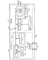
図1は一般的に、プロセス測定システム32の環境を示す。図1は、加圧下にある流体を包含し、プロセス圧力を測定するためのプロセス測定システムに結合されたプロセス配管30を示す。プロセス測定システム32は、配管30に接続されたインパルス配管34を含む。インパルス配管34は、プロセス圧力トランスミッタ36に接続される。一次要素33、たとえばオリフィスプレート、ベンチュリ管、フローノズル等は、プロセス配管30内のインパルス配管34のパイプの間の位置で、プロセス流体に接触する。一次要素33は、流体が一次要素33を通るとき、流体に圧力変化を生じさせる。
FIG. 1 generally illustrates the environment of a
トランスミッタ36はプロセス測定装置であり、インパルス配管34を通してプロセス圧力を受ける。トランスミッタ36はプロセス差圧を感知し、プロセス圧力の関数である標準化された伝送信号を出力する。
The
プロセスループ38は、制御室40からのトランスミッタ36への電力信号と、双方向通信との両方を提供し、数多くのプロセス通信プロトコルによって構築することができる。図示された例では、プロセスループ38は2線式ループである。2線式ループを用いて、4−20mA信号による通常動作中、トランスミッタ36へのすべての電力と、トランスミッタ36への、およびトランスミッタ36からのすべての通信とを伝送する。モデム44または他のネットワークインターフェイスを通したコンピュータ42または他の情報ハンドリングシステムは、トランスミッタ36との通信に用いられる。リモート電圧電源46は、トランスミッタ36に電力供給する。本発明は、ループ38を組み込んでいる環境に限定されない。ワイヤレス等他の通信媒体、および異なるワイヤレス技術を含む他の通信技術に加え、異なる通信プロトコルを、スタンドアローンの装置で用いることができる。
The
図2は、圧力トランスミッタ36の簡略化されたブロック図である。圧力トランスミッタ36は、データバス66を通して共に結合されたセンサモジュール52および電子基板72を含む。センサモジュール電子機器60は、加えられた差圧54を受ける圧力センサ56に結合される。データ接続58は、センサ56をアナログ・ディジタル変換器62に結合させる。また、選択的に設置可能な温度センサ63が、センサモジュールメモリ64とともに図示されている。以下に記述するように、温度センサ63は、圧力センサ56と一体形成することができる。電子基板72は、マイクロコンピュータシステム74、電子メモリモジュール76、ディジタル・アナログ信号変換器78、およびディジタル通信ブロック80を含む。
FIG. 2 is a simplified block diagram of the
差圧を測定するための一つの技術は、Frickらの米国特許第6,295,875号に記載されている。しかし、本発明は、そのような構成に限定されない。 One technique for measuring differential pressure is described in US Pat. No. 6,295,875 to Frick et al. However, the present invention is not limited to such a configuration.
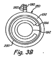
図3Aは、本発明による圧力センサ56を示す側断面図である。圧力センサ56は半体142および144によって形成された圧力センサ本体140を含み、半体はその内部に形成された凹部領域146および148をそれぞれ有し、凹部領域はそれらの間にキャビティ149を形成する。可撓性ダイヤフラム150は、キャビティ149内に取り付けられ、キャビティ149は、インパルス配管94に結合する。ダイヤフラム150は、二つのダイヤフラム半体152および154で形成される。中央コンデンサプレートまたは電極162、164は、ダイヤフラム半体152および154にそれぞれ設けられる。同様に、ダイヤフラム半体152には、外側のコンデンサプレートまたは電極166が設けられ、一方でダイヤフラム半体154には、外側のコンデンサプレートまたは電極172が設けられる。コンデンサプレート162、164、166、168、170および172は、センサ本体140を伴い各々6つ電気コンデンサに用いられる。接触突起180は、中央ダイヤフラム150から延び、その上に電気接点182が設けられる。電気接点182は、172を通して、6つのコンデンサプレートまたは電極162のそれぞれに接続する。
FIG. 3A is a side cross-sectional view illustrating a
図3Bは、コンデンサプレート162および166の配列を含む、可撓性ダイヤフラム150を更に詳細に示す正面平面図である。図3Cは、ダイヤフラム半体154およびセンサ半体144を示す側面斜視図である。図3Cはまた、突起180の接点182に、コンデンサプレートまたは電極170、164を電気的に接続する電気接続192および196を図示する。図3Aおよび3Bはまた、ダイヤフラム150に形成されて、所与の圧力でダイヤフラム150の撓み量を増加させることができる環状ノッチ200を示す。
FIG. 3B is a front plan view showing the
動作中、インパルス配管94を通して、ダイヤフラム154の両側に差圧が加えられる。これにより、キャビティ149内でダイヤフラム150に撓みが生じる。ダイヤフラム150が撓むと、センサ半体142および144によって形成されるキャビティ149の側面に対応する、コンデンサプレート162、164、166、168、170、172の間の距離が変化する。各コンデンサプレート162、164、166、168、170、172の間の電気容量は、センサ本体140に対応して測定され、加えられた差圧と相関させることができる。ダイヤフラム154の撓み量は、加えられた圧力のほか、ダイヤフラム154で用いられた材料と、ダイヤフラム154の寸法との関数である。図3A〜3Bはまた、ダイヤフラム150に形成されて、所与の圧力でダイヤフラム150の撓み量を増加させることができる環状ノッチ200を示す。
During operation, differential pressure is applied across the
一つの好ましい構成では、ダイヤフラム150は、絶縁性結晶材料、たとえばシリコン、石英、サファイア、またはスピネルで形成される。電極は、金属を含むことができ、ダイヤフラム150に付着させるかまたは埋め込みすることができる。センサ本体140は、導電材料、たとえば金属で形成される。本構成により、ダイヤフラム150が組み立てられた後、半体142および144に取り付けられることが可能になる。別の構成では、本体140は、非導電材料であり、各コンデンサプレート162、164、166、168、170、172に対応する電気コンデンサ用の導電材料を含む。一方、いくつかの先行技術の構成では、コンデンサプレートは、センサ本体に形成されたキャビティの壁に設けられる。このことは、センサ本体が絶縁材料、たとえばガラスで満たされることを必要とする。そのような構成では、導電性のダイヤフラムが用いられる。
In one preferred configuration, the
一つの選択的な構成では、キャビティ146の内壁か、またはダイヤフラム150に、特徴部分177が設けられる。特徴部分177は、過剰な圧力が生じて、ダイヤフラム150がキャビティ146の内壁の一つに対して押圧された場合、力を分散させるように構成される。
In one optional configuration, a feature 177 is provided on the inner wall of the
本発明の圧力センサ56は、任意の適切な技術を用いて組み立てることができる。たとえば、二つのダイヤフラム半体152および154は、ともに融合させて、完全なダイヤフラム150を形成することができる。さらなる特徴として、たとえばダイヤフラムの形状およびヒンジ点を、所望のとおりに製造することができる。いくつかの実施形態では、ダイヤフラム150に、圧力センサ56の温度測定で用いるための温度センサ210が加工される。温度を用いて、圧力測定での温度関連の誤差を補償することができる。また、温度信号は、プロセス流体に関する他の情報を判断するために、たとえば流量算出での使用に用いることができる。
The
一つの実施形態では、完全なダイヤフラム150は、キャビティ149からセンサ本体140を通って本体140の外に延びる突起180を備える2つの金属製センサ半体142および144の間に溶接される。突起180が二つのセンサ半体142および144と交わる領域は、たとえばろう付け技術を用いてシールすることができる。本構成は、いくつかの先行技術構成で用いられているようなガラスではなく、半導体材料に取り付けることができる電極を備えたソリッドステートセンサを提供する。これにより、ヒステリシスが減少し、改善された安定性が提供される。さらに、ダイヤフラム150の高圧側および低圧側のコンデンサ電極はきわめて接近したままであり、このことは、温度限界を超える改善された性能をさらに提供する。中央ダイヤフラム150は、標準的な半導体製造技術を用いて製造することができ、これにより製造の簡略化、コスト低減およびより優れた公差管理が可能になる。センサの特徴部分、たとえばヒンジ点、キャビティ形状、電極、電極リード線および温度センサは、先行技術の設計で用いられているようなガラス/金属圧力センサハーフセルにではなく、半導体中央ダイヤフラム構造に、エッチングするか、蒸着させるかまたは別の方法で形成される。これにより、製造が簡略化され、製造コストが低くなり、改善された性能につながるより優れた公差管理が提供される。
In one embodiment, the
図3Aを再度参照すると、ダイヤフラム154の中の、ダイヤフラム半体150および152の間に位置付けられた、選択的に設置可能な内側キャビティ220が図示されている。容量性プレートまたは電極222、224は、内側キャビティ220の側壁上に配置される。内側キャビティ220は、容量性プレート222および224の間の間隔が、加えられたライン圧力の関数として変化するように構成される。この選択的な構成は、ライン圧力とともに、インパルス配管94を通してダイヤフラム150に加えられる差圧も測定可能にする。そのような構成では、電気接点は、コンデンサプレートまたは電極222、224に接続する突起180上に設けられる。
Referring again to FIG. 3A, a selectively installable
図4は、圧力センサ56を示しているセンサモジュール52の、一つの実施形態の簡略化された断面図である。圧力センサ56は、キャビティ92からプロセス流体を分離する分離ダイヤフラム90を通してプロセス流体に結合する。キャビティ92は、インパルス配管94を通して、圧力センサモジュール56に結合する。実質的に非圧縮性の充填流体は、キャビティ92およびインパルス配管94を満たす。プロセス流体からの圧力がダイヤフラム90に対して加えられると、圧力は、インパルス配管94内の充填流体を通して、圧力センサ56に伝達される。
FIG. 4 is a simplified cross-sectional view of one embodiment of
本発明のセンサでは、特徴部分、たとえばヒンジ点、キャビティ形状、電極、電極リード線および温度センサは、いくつかの設計で用いられているようなガラス/金属ハーフセルではなく、固体構造に、エッチングするか、蒸着させるかまたは別の方法で形成することができる。これにより、製造コストが低減し、改善された性能を可能にするより優れた公差管理が提供される。さらに、圧力センサの外側は、金属体で形成され、これにより過度の超過圧力を容易に包含することができる。本構造は、任意の適切な技術、たとえばレーザ溶接またはろう付けを用いて、形成し取り付けることができる。変化する静電容量に基づいて、加えられた圧力を判断するために用いられる測定回路を、突起180にきわめて接近させて取り付けることができる。これにより、電気接続からコンデンサプレートへの浮遊静電容量による誤差が低減する。いくつかの構成では、本回路は突起180上に直接設けられる。そのような構成では、測定回路は、突起180に取り付けられるか、または突起180上に直接製造されることができる。
In the sensor of the present invention, features such as hinge points, cavity shapes, electrodes, electrode leads and temperature sensors etch into a solid structure rather than a glass / metal half cell as used in some designs. Or can be vapor deposited or otherwise formed. This reduces manufacturing costs and provides better tolerance management that allows improved performance. Further, the outside of the pressure sensor is formed of a metal body, which can easily include excessive overpressure. The structure can be formed and attached using any suitable technique, such as laser welding or brazing. A measurement circuit used to determine the applied pressure based on the changing capacitance can be mounted in close proximity to the
好ましい実施形態を参照して本発明を説明してきたが、当業者においては、本発明の本質および範囲から逸脱することなく、形態および細部に変更を加えてもよいことが認識されるであろう。圧力測定は、任意の適切な技術を用いて、上述の圧力センサを用いて行われてもよい。一つの技術例は、2005年5月27日出願の米国特許出願番号第11/140,681号、Line Pressure Measurement Using Differential Pressure Sensorに記載され、これは参照により本明細書に組み入れられる。図面に図示された、4つの異なるコンデンサが形成されている特定の構成を用いて、出願番号第11/140,681号に記載されたような誤差の較正を行うことができる。一つの実施形態では、単一のコンデンサ、二つのコンデンサ等を含む任意の数のコンデンサが用いられる。本発明は、任意の特定の数のコンデンサまたはコンデンサプレートの構成に限定されない。上記の明細書では、オイル充填流体について論じているが、空気または気体充填を含む他の充填流体を用いてもよい。ダイヤフラムは、所望のとおりに撓むように構成することができる。一つの構成では、ダイヤフラムの撓みは、1オングストロームより小さくしてもよい。中央ダイヤフラム構造は、特定の実施のため、所望のとおりに、任意の形状および/または特性を有することができる。たとえば、ダイヤフラムは、一定点での曲げを促進するためのヒンジ特性、シーリング特性等を有することができる。これにより、ダイヤフラムが特定の環境でのセンサ、たとえば差圧センサの性能のために最適化されることが可能になる。これらの特性および形状は、基本部分に追加の構造が付加される加法的な技術、または基本部分から材料を除去して、所望の形状または特性を形成する減法的な技術の両方を含む、任意の適切な方法を用いて形成することができる。 Although the present invention has been described with reference to preferred embodiments, workers skilled in the art will recognize that changes may be made in form and detail without departing from the spirit and scope of the invention. . The pressure measurement may be performed using the pressure sensor described above using any suitable technique. One example technique is described in US Patent Application No. 11 / 140,681, filed May 27, 2005, Line Pressure Measurement Using Differential Pressure Sensor, which is incorporated herein by reference. The particular configuration shown in the drawing, in which four different capacitors are formed, can be used to perform error calibration as described in application Ser. No. 11 / 140,681. In one embodiment, any number of capacitors is used including a single capacitor, two capacitors, and the like. The present invention is not limited to any particular number of capacitor or capacitor plate configurations. While the above specification discusses oil-filled fluids, other fill fluids including air or gas fills may be used. The diaphragm can be configured to flex as desired. In one configuration, the diaphragm deflection may be less than 1 angstrom. The central diaphragm structure can have any shape and / or characteristics as desired for a particular implementation. For example, the diaphragm can have hinge characteristics, sealing characteristics, etc. to promote bending at a certain point. This allows the diaphragm to be optimized for the performance of a sensor in a particular environment, such as a differential pressure sensor. These characteristics and shapes are optional, including both additive techniques that add additional structure to the base part, or subtractive techniques that remove material from the base part to form the desired shape or characteristic. Can be formed using any suitable method.
Claims (18)
前記キャビティを通して前記圧力センサ本体内部に延びる圧力接点と、
前記圧力接点を通して前記キャビティに加えられた圧力に応じて撓むように構成された、前記キャビティ内の可撓性ダイヤフラムと、
前記可撓性ダイヤフラムによって担持された前記キャビティ内の電極と、
前記圧力センサ本体の外側に伸びる、前記電極との電気接点と、
を含み、
前記圧力センサ本体を導電材料で形成し、前記可撓性ダイヤフラムを絶縁材料で形成し、
前記電極が、前記圧力センサ本体とともに可変コンデンサを形成するように構成され、加えられた圧力に応じて変動する静電容量を提供する、プロセス流体の圧力を感知するための圧力センサ。 A pressure sensor body having a cavity formed therein;
A pressure contact extending into the pressure sensor body through the cavity;
A flexible diaphragm in the cavity configured to flex in response to pressure applied to the cavity through the pressure contact;
An electrode in the cavity carried by the flexible diaphragm;
An electrical contact with the electrode extending outside the pressure sensor body;
Including
The pressure sensor body is formed of a conductive material, the flexible diaphragm is formed of an insulating material,
A pressure sensor for sensing the pressure of a process fluid, wherein the electrode is configured to form a variable capacitor with the pressure sensor body and provides a capacitance that varies in response to an applied pressure.
前記圧力センサ本体を導電材料で形成し、前記可撓性ダイヤフラムを絶縁材料で形成すること、
前記可撓性ダイヤフラムによって担持された電極を前記圧力センサ本体の前記キャビティ内に備えることと、
前記電極を、前記圧力センサ本体とともに可変コンデンサを形成するように構成することで、加えられた圧力に応じて変動する静電容量を提供することと、
前記圧力センサ本体を通して前記可撓性ダイヤフラムに圧力を加えて、その結果撓みを生じさせることと、
前記可撓性ダイヤフラムによって担持された前記電極と、前記圧力センサ本体との間の静電容量の変化を測定することと、
測定された静電容量の変化に基づいて、圧力を定めることと、
を含む、プロセス流体の圧力を感知する方法。 Providing a flexible diaphragm in the cavity of the pressure sensor body;
Forming the pressure sensor body from a conductive material, and forming the flexible diaphragm from an insulating material;
Providing an electrode carried by the flexible diaphragm in the cavity of the pressure sensor body;
Providing the capacitance to vary according to the applied pressure by configuring the electrode to form a variable capacitor with the pressure sensor body; and
Applying pressure to the flexible diaphragm through the pressure sensor body, resulting in deflection;
Measuring a change in capacitance between the electrode carried by the flexible diaphragm and the pressure sensor body;
Determining a pressure based on the measured change in capacitance;
A method for sensing the pressure of a process fluid.
Applications Claiming Priority (3)
| Application Number | Priority Date | Filing Date | Title |
|---|---|---|---|
| US11/312,062 | 2005-12-20 | ||
| US11/312,062 US7415886B2 (en) | 2005-12-20 | 2005-12-20 | Pressure sensor with deflectable diaphragm |
| PCT/US2006/046742 WO2007075290A1 (en) | 2005-12-20 | 2006-12-07 | Pressure sensor with deflectable diaphragm |
Publications (3)
| Publication Number | Publication Date |
|---|---|
| JP2009520206A JP2009520206A (en) | 2009-05-21 |
| JP2009520206A5 JP2009520206A5 (en) | 2009-12-10 |
| JP5547894B2 true JP5547894B2 (en) | 2014-07-16 |
Family
ID=37847241
Family Applications (1)
| Application Number | Title | Priority Date | Filing Date |
|---|---|---|---|
| JP2008547276A Expired - Fee Related JP5547894B2 (en) | 2005-12-20 | 2006-12-07 | Pressure sensor with flexible diaphragm |
Country Status (5)
| Country | Link |
|---|---|
| US (1) | US7415886B2 (en) |
| EP (1) | EP1974195B1 (en) |
| JP (1) | JP5547894B2 (en) |
| CN (1) | CN101341385B (en) |
| WO (1) | WO2007075290A1 (en) |
Cited By (1)
| Publication number | Priority date | Publication date | Assignee | Title |
|---|---|---|---|---|
| JP2018523116A (en) * | 2015-06-30 | 2018-08-16 | ローズマウント インコーポレイテッド | Polymer remote seal system for disposable containers |
Families Citing this family (10)
| Publication number | Priority date | Publication date | Assignee | Title |
|---|---|---|---|---|
| DE102005017853A1 (en) * | 2005-04-18 | 2006-10-19 | Siemens Ag | Pressure sensor device |
| US8429978B2 (en) * | 2010-03-30 | 2013-04-30 | Rosemount Inc. | Resonant frequency based pressure sensor |
| US9316553B2 (en) * | 2014-03-26 | 2016-04-19 | Rosemount Inc. | Span line pressure effect compensation for diaphragm pressure sensor |
| US10836990B2 (en) | 2016-12-23 | 2020-11-17 | Cyberoptics Corporation | Sensor interface for single-use containers |
| US10584309B2 (en) | 2017-02-06 | 2020-03-10 | Rosemount Inc. | Pressure transducer for single-use containers |
| CN107101751A (en) * | 2017-02-28 | 2017-08-29 | 宝力马(苏州)传感技术有限公司 | A kind of novel capacitance-type pressure sensor and preparation method thereof |
| US11046575B2 (en) * | 2017-10-31 | 2021-06-29 | Encite Llc | Broad range micro pressure sensor |
| WO2019222598A1 (en) | 2018-05-17 | 2019-11-21 | Rosemount Inc. | Measuring element and measuring device comprising the same |
| CN108593187A (en) * | 2018-05-23 | 2018-09-28 | 金陵科技学院 | Ceramic capacitive pressure sensor and the method for improving pressure detecting precision |
| US11371902B2 (en) | 2019-12-27 | 2022-06-28 | Rosemount Inc. | Process venting feature for use in sensor applications with a process fluid barrier |
Family Cites Families (100)
| Publication number | Priority date | Publication date | Assignee | Title |
|---|---|---|---|---|
| US2533339A (en) * | 1946-06-22 | 1950-12-12 | Jabez Burns & Sons Inc | Flammable vapor protection |
| US3012432A (en) * | 1957-09-23 | 1961-12-12 | Richard H Moore | Leak tester |
| GB1023042A (en) * | 1962-05-07 | 1966-03-16 | Wayne Kerr Lab Ltd | Improvements in or relating to pressure responsive apparatus |
| US3232712A (en) * | 1962-08-16 | 1966-02-01 | Continental Lab Inc | Gas detector and analyzer |
| US3374112A (en) * | 1964-03-05 | 1968-03-19 | Yeda Res & Dev | Method and apparatus for controlled deposition of a thin conductive layer |
| US3249833A (en) * | 1964-11-16 | 1966-05-03 | Robert E Vosteen | Capacitor transducer |
| US3557621A (en) * | 1969-07-07 | 1971-01-26 | C G S Scient Corp Inc | Variable capacitance detecting devices |
| GB1354025A (en) * | 1970-05-25 | 1974-06-05 | Medicor Muevek | Capacitive pressure transducer |
| US3924219A (en) * | 1971-12-22 | 1975-12-02 | Minnesota Mining & Mfg | Gas detection device |
| US3808480A (en) * | 1973-04-16 | 1974-04-30 | Bunker Ramo | Capacitive pressure transducer |
| US4008619A (en) * | 1975-11-17 | 1977-02-22 | Mks Instruments, Inc. | Vacuum monitoring |
| US4177496A (en) * | 1976-03-12 | 1979-12-04 | Kavlico Corporation | Capacitive pressure transducer |
| US4158217A (en) * | 1976-12-02 | 1979-06-12 | Kaylico Corporation | Capacitive pressure transducer with improved electrode |
| US4120206A (en) | 1977-01-17 | 1978-10-17 | Rosemount Inc. | Differential pressure sensor capsule with low acceleration sensitivity |
| US4168518A (en) * | 1977-05-10 | 1979-09-18 | Lee Shih Y | Capacitor transducer |
| US4172387A (en) * | 1978-06-05 | 1979-10-30 | The Foxboro Company | Pressure responsive apparatus |
| US4227419A (en) * | 1979-09-04 | 1980-10-14 | Kavlico Corporation | Capacitive pressure transducer |
| US4244226A (en) * | 1979-10-04 | 1981-01-13 | Honeywell Inc. | Distance measuring apparatus and a differential pressure transmitter utilizing the same |
| US4322775A (en) * | 1979-10-29 | 1982-03-30 | Delatorre Leroy C | Capacitive pressure sensor |
| US4434451A (en) * | 1979-10-29 | 1984-02-28 | Delatorre Leroy C | Pressure sensors |
| US4287553A (en) * | 1980-06-06 | 1981-09-01 | The Bendix Corporation | Capacitive pressure transducer |
| US4336567A (en) * | 1980-06-30 | 1982-06-22 | The Bendix Corporation | Differential pressure transducer |
| US4370890A (en) * | 1980-10-06 | 1983-02-01 | Rosemount Inc. | Capacitive pressure transducer with isolated sensing diaphragm |
| US4358814A (en) * | 1980-10-27 | 1982-11-09 | Setra Systems, Inc. | Capacitive pressure sensor |
| US4422335A (en) * | 1981-03-25 | 1983-12-27 | The Bendix Corporation | Pressure transducer |
| US4458537A (en) * | 1981-05-11 | 1984-07-10 | Combustion Engineering, Inc. | High accuracy differential pressure capacitive transducer |
| US4389895A (en) * | 1981-07-27 | 1983-06-28 | Rosemount Inc. | Capacitance pressure sensor |
| US4466290A (en) * | 1981-11-27 | 1984-08-21 | Rosemount Inc. | Apparatus for conveying fluid pressures to a differential pressure transducer |
| US4455874A (en) * | 1981-12-28 | 1984-06-26 | Paroscientific, Inc. | Digital pressure transducer |
| US4422125A (en) * | 1982-05-21 | 1983-12-20 | The Bendix Corporation | Pressure transducer with an invariable reference capacitor |
| DE3238430A1 (en) * | 1982-10-16 | 1984-04-19 | Philips Patentverwaltung Gmbh, 2000 Hamburg | DIFFERENTIAL PRESSURE SENSOR |
| JPS59127148U (en) * | 1983-02-14 | 1984-08-27 | 株式会社島津製作所 | Capacitive pressure/differential pressure transmitter |
| US4558184A (en) * | 1983-02-24 | 1985-12-10 | At&T Bell Laboratories | Integrated capacitive transducer |
| DE3340834A1 (en) | 1983-11-11 | 1985-05-23 | Philips Patentverwaltung Gmbh, 2000 Hamburg | Circuit arrangement for keeping the temperature-dependent sensitivity of a differential-pressure measurement apparatus constant |
| US4490773A (en) * | 1983-12-19 | 1984-12-25 | United Technologies Corporation | Capacitive pressure transducer |
| US4542436A (en) * | 1984-04-10 | 1985-09-17 | Johnson Service Company | Linearized capacitive pressure transducer |
| US4562742A (en) * | 1984-08-07 | 1986-01-07 | Bell Microcomponents, Inc. | Capacitive pressure transducer |
| US4578735A (en) * | 1984-10-12 | 1986-03-25 | Knecht Thomas A | Pressure sensing cell using brittle diaphragm |
| US4586108A (en) | 1984-10-12 | 1986-04-29 | Rosemount Inc. | Circuit for capacitive sensor made of brittle material |
| US4670733A (en) * | 1985-07-01 | 1987-06-02 | Bell Microsensors, Inc. | Differential pressure transducer |
| IL82960A0 (en) * | 1986-06-30 | 1987-12-20 | Rosemount Inc | Differential pressure sensor |
| US4860232A (en) * | 1987-04-22 | 1989-08-22 | Massachusetts Institute Of Technology | Digital technique for precise measurement of variable capacitance |
| FR2614986B1 (en) * | 1987-05-07 | 1989-08-18 | Otic Fischer & Porter | CAPACITIVE CELL STRUCTURE FOR MEASURING DIFFERENTIAL PRESSURES |
| US4785669A (en) * | 1987-05-18 | 1988-11-22 | Mks Instruments, Inc. | Absolute capacitance manometers |
| JP2514067Y2 (en) * | 1987-06-29 | 1996-10-16 | 京セラ株式会社 | Ceramic transformer |
| US4875369A (en) * | 1987-09-08 | 1989-10-24 | Panex Corporation | Pressure sensor system |
| US4878012A (en) * | 1988-06-10 | 1989-10-31 | Rosemount Inc. | Charge balanced feedback transmitter |
| US4977480A (en) * | 1988-09-14 | 1990-12-11 | Fuji Koki Mfg. Co., Ltd. | Variable-capacitance type sensor and variable-capacitance type sensor system using the same |
| US4926674A (en) * | 1988-11-03 | 1990-05-22 | Innovex Inc. | Self-zeroing pressure signal generator |
| US4951174A (en) * | 1988-12-30 | 1990-08-21 | United Technologies Corporation | Capacitive pressure sensor with third encircling plate |
| US5194819A (en) * | 1990-08-10 | 1993-03-16 | Setra Systems, Inc. | Linearized capacitance sensor system |
| US5094109A (en) * | 1990-12-06 | 1992-03-10 | Rosemount Inc. | Pressure transmitter with stress isolation depression |
| US5168419A (en) * | 1991-07-16 | 1992-12-01 | Panex Corporation | Capacitor and pressure transducer |
| DE4124662A1 (en) | 1991-07-25 | 1993-01-28 | Fibronix Sensoren Gmbh | RELATIVE PRESSURE SENSOR |
| US5230250A (en) * | 1991-09-03 | 1993-07-27 | Delatorre Leroy C | Capacitor and pressure transducer |
| JP3182807B2 (en) * | 1991-09-20 | 2001-07-03 | 株式会社日立製作所 | Multifunctional fluid measurement transmission device and fluid volume measurement control system using the same |
| US5233875A (en) * | 1992-05-04 | 1993-08-10 | Kavlico Corporation | Stable capacitive pressure transducer system |
| US5329818A (en) * | 1992-05-28 | 1994-07-19 | Rosemount Inc. | Correction of a pressure indication in a pressure transducer due to variations of an environmental condition |
| US5492016A (en) * | 1992-06-15 | 1996-02-20 | Industrial Sensors, Inc. | Capacitive melt pressure measurement with center-mounted electrode post |
| CA2169824A1 (en) | 1993-09-24 | 1995-03-30 | Roger L. Frick | Pressure transmitter isolation diaphragm |
| DE4333753A1 (en) | 1993-10-04 | 1994-05-11 | Bosch Gmbh Robert | Capacitive difference pressure sensor - has carrier supporting counter-electrodes between facing membranes carrying capacitor electrodes |
| US5542300A (en) * | 1994-01-24 | 1996-08-06 | Setra Systems, Inc. | Low cost, center-mounted capacitive pressure sensor |
| US5642301A (en) * | 1994-01-25 | 1997-06-24 | Rosemount Inc. | Transmitter with improved compensation |
| WO1996017235A1 (en) * | 1994-11-30 | 1996-06-06 | Rosemount Inc. | Pressure transmitter with fill fluid loss detection |
| US5637802A (en) * | 1995-02-28 | 1997-06-10 | Rosemount Inc. | Capacitive pressure sensor for a pressure transmitted where electric field emanates substantially from back sides of plates |
| US6484585B1 (en) * | 1995-02-28 | 2002-11-26 | Rosemount Inc. | Pressure sensor for a pressure transmitter |
| US5705978A (en) * | 1995-09-29 | 1998-01-06 | Rosemount Inc. | Process control transmitter |
| US5992240A (en) * | 1995-11-21 | 1999-11-30 | Fuji Electric Co., Ltd. | Pressure detecting apparatus for measuring pressure based on detected capacitance |
| US5757608A (en) * | 1996-01-25 | 1998-05-26 | Alliedsignal Inc. | Compensated pressure transducer |
| US6654697B1 (en) * | 1996-03-28 | 2003-11-25 | Rosemount Inc. | Flow measurement with diagnostics |
| US5668322A (en) | 1996-06-13 | 1997-09-16 | Rosemount Inc. | Apparatus for coupling a transmitter to process fluid having a sensor extension selectively positionable at a plurality of angles |
| DE19633630A1 (en) * | 1996-08-21 | 1998-02-26 | Endress Hauser Gmbh Co | Evaluation unit of a differential pressure sensor |
| US5753820A (en) * | 1996-10-25 | 1998-05-19 | Arthur D. Little, Inc. | Fluid pressure sensing unit incorporating diaphragm deflection sensing array |
| US20040015069A1 (en) * | 1996-12-27 | 2004-01-22 | Brown David Lloyd | System for locating inflamed plaque in a vessel |
| FR2762389B1 (en) * | 1997-04-17 | 1999-05-21 | Commissariat Energie Atomique | FLEXIBLE MEMBRANE MICROSYSTEM FOR PRESSURE SENSOR AND METHOD FOR PRODUCING THE SAME |
| US5911162A (en) * | 1997-06-20 | 1999-06-08 | Mks Instruments, Inc. | Capacitive pressure transducer with improved electrode support |
| US5974893A (en) * | 1997-07-24 | 1999-11-02 | Texas Instruments Incorporated | Combined pressure responsive transducer and temperature sensor apparatus |
| WO1999053286A1 (en) | 1998-04-09 | 1999-10-21 | Ploechinger Heinz | Capacitive pressure or force sensor structure and method for producing the same |
| JP3567089B2 (en) * | 1998-10-12 | 2004-09-15 | 株式会社日立製作所 | Capacitive pressure sensor |
| US6295875B1 (en) * | 1999-05-14 | 2001-10-02 | Rosemount Inc. | Process pressure measurement devices with improved error compensation |
| DE69936794T2 (en) * | 1999-08-20 | 2008-04-30 | Hitachi, Ltd. | SEMICONDUCTOR PRESSURE SENSOR AND DEVICE FOR DETECTING PRINTING |
| US6701274B1 (en) * | 1999-08-27 | 2004-03-02 | Rosemount Inc. | Prediction of error magnitude in a pressure transmitter |
| US6520020B1 (en) * | 2000-01-06 | 2003-02-18 | Rosemount Inc. | Method and apparatus for a direct bonded isolated pressure sensor |
| DE60125018T2 (en) | 2000-02-11 | 2007-06-28 | Rosemount Inc., Eden Prairie | OPTICAL PRINTER |
| US6662662B1 (en) | 2000-05-04 | 2003-12-16 | Rosemount, Inc. | Pressure transmitter with improved isolator system |
| DE10052053A1 (en) * | 2000-10-19 | 2002-04-25 | Endress Hauser Gmbh Co | Pressure measurement cell has contact pin fed through base body to electrode for capacitance measurement; contact pin, jointing solder and membrane bed form smooth surface |
| DE10117142A1 (en) * | 2001-04-05 | 2002-10-10 | Endress & Hauser Gmbh & Co Kg | Capacitive differential pressure sensor incorporates correction of calculated differential pressure for eliminating dependency on network pressure |
| US6516672B2 (en) * | 2001-05-21 | 2003-02-11 | Rosemount Inc. | Sigma-delta analog to digital converter for capacitive pressure sensor and process transmitter |
| US6828801B1 (en) * | 2001-10-26 | 2004-12-07 | Welch Allyn, Inc. | Capacitive sensor |
| US6675655B2 (en) | 2002-03-21 | 2004-01-13 | Rosemount Inc. | Pressure transmitter with process coupling |
| US6647794B1 (en) * | 2002-05-06 | 2003-11-18 | Rosemount Inc. | Absolute pressure sensor |
| AU2003287645A1 (en) * | 2002-11-12 | 2004-06-03 | Cidra Corporation | An apparatus having an array of piezoelectric film sensors for measuring parameters of a process flow within a pipe |
| EP1631797A2 (en) * | 2003-06-05 | 2006-03-08 | CiDra Corporation | Apparatus for measuring velocity and flow rate of a fluid having a non-negligible axial mach number using an array of sensors |
| JP4624351B2 (en) * | 2003-07-18 | 2011-02-02 | ローズマウント インコーポレイテッド | Process diagnosis |
| US7523667B2 (en) * | 2003-12-23 | 2009-04-28 | Rosemount Inc. | Diagnostics of impulse piping in an industrial process |
| US6945115B1 (en) * | 2004-03-04 | 2005-09-20 | General Mems Corporation | Micromachined capacitive RF pressure sensor |
| US7577543B2 (en) * | 2005-03-11 | 2009-08-18 | Honeywell International Inc. | Plugged impulse line detection |
| US7401522B2 (en) | 2005-05-26 | 2008-07-22 | Rosemount Inc. | Pressure sensor using compressible sensor body |
| US7334484B2 (en) | 2005-05-27 | 2008-02-26 | Rosemount Inc. | Line pressure measurement using differential pressure sensor |
| JP5222457B2 (en) * | 2005-09-26 | 2013-06-26 | 株式会社日立製作所 | Sensors and sensor modules |
-
2005
- 2005-12-20 US US11/312,062 patent/US7415886B2/en active Active
-
2006
- 2006-12-07 CN CN2006800483176A patent/CN101341385B/en active Active
- 2006-12-07 EP EP06844974.3A patent/EP1974195B1/en active Active
- 2006-12-07 JP JP2008547276A patent/JP5547894B2/en not_active Expired - Fee Related
- 2006-12-07 WO PCT/US2006/046742 patent/WO2007075290A1/en active Application Filing
Cited By (1)
| Publication number | Priority date | Publication date | Assignee | Title |
|---|---|---|---|---|
| JP2018523116A (en) * | 2015-06-30 | 2018-08-16 | ローズマウント インコーポレイテッド | Polymer remote seal system for disposable containers |
Also Published As
| Publication number | Publication date |
|---|---|
| CN101341385A (en) | 2009-01-07 |
| US20070151349A1 (en) | 2007-07-05 |
| WO2007075290A1 (en) | 2007-07-05 |
| CN101341385B (en) | 2011-11-23 |
| EP1974195B1 (en) | 2018-11-07 |
| US7415886B2 (en) | 2008-08-26 |
| EP1974195A1 (en) | 2008-10-01 |
| JP2009520206A (en) | 2009-05-21 |
Similar Documents
| Publication | Publication Date | Title |
|---|---|---|
| JP5547894B2 (en) | Pressure sensor with flexible diaphragm | |
| US6295875B1 (en) | Process pressure measurement devices with improved error compensation | |
| RU2416786C2 (en) | Measuring pressure in pipeline using differential pressure sensor | |
| RU2538363C2 (en) | Differential pressure sensor with measurement of line pressure | |
| EP3123134B1 (en) | Span line pressure effect compensation for diaphragm pressure sensor | |
| CN100406867C (en) | Low-cost capacitive pressure transmitter with plate coating, particle filter, self-contained | |
| JPH11295176A (en) | Differential pressure sensor | |
| JP7459257B2 (en) | High range differential pressure sensor | |
| CN219977636U (en) | Differential pressure sensor for sensing differential pressure of process fluid |
Legal Events
| Date | Code | Title | Description |
|---|---|---|---|
| A521 | Written amendment |
Free format text: JAPANESE INTERMEDIATE CODE: A523 Effective date: 20091023 |
|
| A621 | Written request for application examination |
Free format text: JAPANESE INTERMEDIATE CODE: A621 Effective date: 20091023 |
|
| A977 | Report on retrieval |
Free format text: JAPANESE INTERMEDIATE CODE: A971007 Effective date: 20120328 |
|
| A131 | Notification of reasons for refusal |
Free format text: JAPANESE INTERMEDIATE CODE: A131 Effective date: 20120807 |
|
| A601 | Written request for extension of time |
Free format text: JAPANESE INTERMEDIATE CODE: A601 Effective date: 20121107 |
|
| A602 | Written permission of extension of time |
Free format text: JAPANESE INTERMEDIATE CODE: A602 Effective date: 20121114 |
|
| A601 | Written request for extension of time |
Free format text: JAPANESE INTERMEDIATE CODE: A601 Effective date: 20121207 |
|
| A602 | Written permission of extension of time |
Free format text: JAPANESE INTERMEDIATE CODE: A602 Effective date: 20121214 |
|
| A521 | Written amendment |
Free format text: JAPANESE INTERMEDIATE CODE: A523 Effective date: 20130107 |
|
| A131 | Notification of reasons for refusal |
Free format text: JAPANESE INTERMEDIATE CODE: A131 Effective date: 20131029 |
|
| A601 | Written request for extension of time |
Free format text: JAPANESE INTERMEDIATE CODE: A601 Effective date: 20140127 |
|
| A602 | Written permission of extension of time |
Free format text: JAPANESE INTERMEDIATE CODE: A602 Effective date: 20140203 |
|
| A521 | Written amendment |
Free format text: JAPANESE INTERMEDIATE CODE: A523 Effective date: 20140227 |
|
| A131 | Notification of reasons for refusal |
Free format text: JAPANESE INTERMEDIATE CODE: A131 Effective date: 20140401 |
|
| A521 | Written amendment |
Free format text: JAPANESE INTERMEDIATE CODE: A523 Effective date: 20140403 |
|
| TRDD | Decision of grant or rejection written | ||
| A01 | Written decision to grant a patent or to grant a registration (utility model) |
Free format text: JAPANESE INTERMEDIATE CODE: A01 Effective date: 20140430 |
|
| A61 | First payment of annual fees (during grant procedure) |
Free format text: JAPANESE INTERMEDIATE CODE: A61 Effective date: 20140516 |
|
| R150 | Certificate of patent or registration of utility model |
Ref document number: 5547894 Country of ref document: JP Free format text: JAPANESE INTERMEDIATE CODE: R150 |
|
| R250 | Receipt of annual fees |
Free format text: JAPANESE INTERMEDIATE CODE: R250 |
|
| R250 | Receipt of annual fees |
Free format text: JAPANESE INTERMEDIATE CODE: R250 |
|
| R250 | Receipt of annual fees |
Free format text: JAPANESE INTERMEDIATE CODE: R250 |
|
| LAPS | Cancellation because of no payment of annual fees |