EP1973459B1 - Dish washer - Google Patents
Dish washer Download PDFInfo
- Publication number
- EP1973459B1 EP1973459B1 EP06823933.4A EP06823933A EP1973459B1 EP 1973459 B1 EP1973459 B1 EP 1973459B1 EP 06823933 A EP06823933 A EP 06823933A EP 1973459 B1 EP1973459 B1 EP 1973459B1
- Authority
- EP
- European Patent Office
- Prior art keywords
- flow channel
- wash water
- filter
- dish washer
- sump
- Prior art date
- Legal status (The legal status is an assumption and is not a legal conclusion. Google has not performed a legal analysis and makes no representation as to the accuracy of the status listed.)
- Active
Links
Images


Classifications
-
- A—HUMAN NECESSITIES
- A47—FURNITURE; DOMESTIC ARTICLES OR APPLIANCES; COFFEE MILLS; SPICE MILLS; SUCTION CLEANERS IN GENERAL
- A47L—DOMESTIC WASHING OR CLEANING; SUCTION CLEANERS IN GENERAL
- A47L15/00—Washing or rinsing machines for crockery or tableware
- A47L15/42—Details
- A47L15/4214—Water supply, recirculation or discharge arrangements; Devices therefor
- A47L15/4225—Arrangements or adaption of recirculation or discharge pumps
-
- A—HUMAN NECESSITIES
- A47—FURNITURE; DOMESTIC ARTICLES OR APPLIANCES; COFFEE MILLS; SPICE MILLS; SUCTION CLEANERS IN GENERAL
- A47L—DOMESTIC WASHING OR CLEANING; SUCTION CLEANERS IN GENERAL
- A47L15/00—Washing or rinsing machines for crockery or tableware
- A47L15/42—Details
- A47L15/4202—Water filter means or strainers
- A47L15/4204—Flat filters
-
- A—HUMAN NECESSITIES
- A47—FURNITURE; DOMESTIC ARTICLES OR APPLIANCES; COFFEE MILLS; SPICE MILLS; SUCTION CLEANERS IN GENERAL
- A47L—DOMESTIC WASHING OR CLEANING; SUCTION CLEANERS IN GENERAL
- A47L15/00—Washing or rinsing machines for crockery or tableware
- A47L15/42—Details
- A47L15/4202—Water filter means or strainers
- A47L15/4206—Tubular filters
-
- A—HUMAN NECESSITIES
- A47—FURNITURE; DOMESTIC ARTICLES OR APPLIANCES; COFFEE MILLS; SPICE MILLS; SUCTION CLEANERS IN GENERAL
- A47L—DOMESTIC WASHING OR CLEANING; SUCTION CLEANERS IN GENERAL
- A47L15/00—Washing or rinsing machines for crockery or tableware
- A47L15/42—Details
- A47L15/4214—Water supply, recirculation or discharge arrangements; Devices therefor
- A47L15/4219—Water recirculation
- A47L15/4221—Arrangements for redirection of washing water, e.g. water diverters to selectively supply the spray arms
Definitions
- the present invention relates to a dish washer, and more particularly, to a dish washer having improved washing efficiency while being constructed in a compact structure.
- a general dish washer is an apparatus that injects wash water to dishes so as to wash the dishes, and dries and/or sterilizes the washed dishes.
- FIG. 1 is a view schematically illustrating the whole construction of a conventional dish washer
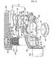
- FIG. 2 is an exploded perspective view fully illustrating a drive unit of the dish washer shown in FIG. 1
- FIG. 3 is a top view illustrating a flow channel structure of a filter housing shown in FIG. 2
- FIG. 4 is a sectional view illustrating the flow of wash water in the drive unit shown in FIG. 2 during a washing operation.
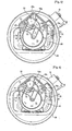
- FIG. 5 is a top view illustrating the flow of wash water in the filter housing shown in FIG. 2 during a washing operation
- FIG. 6 is a top view illustrating the flow of wash water in the filter housing shown in FIG. 2 during a draining operation.
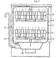
- the conventional dish washer is constructed in a structure in which upper and lower washing arms 4 and 5, upper and lower racks 6 and 7, and a drive unit 10 are mounted in a tub 1.
- the drive unit 10 To the drive unit 10 are connected upper and lower connection pipes 2 and 3, through which wash water is supplied to the upper and lower washing arms 4 arid 5, respectively, and a drainage hose 9, through which the wash water is drained.
- the upper and lower washing arms 4 and 5 are connected to the upper and lower connection pipes 2 and 3, respectively.
- the upper rack 6 is mounted above the upper washing arm 4, and the lower rack 7 is mounted above the lower washing arm 5.
- the upper and lower washing arms 4 and 5 are rotatably mounted above the drive unit 10.
- the respective washing arms 4 and 5 are provided with injection holes, through which wash water is injected toward the corresponding racks.
- the lower washing arm 5 is provided with injection holes, through which wash water is injected toward the drive unit 10 such that food wastes are removed from a filter of the drive unit 10 by the injected wash water.
- the drive unit 10 includes a sump 20 for receiving wash water, a heater 30 mounted at the sump 20 for heating the wash water, a washing pump 41 and 42 mounted at the sump 20 for pumping the wash water, a drainage pump 51 and 52 mounted at the sump 20 for draining the wash water, and a filtering unit for guiding some of the pumped wash water to the washing arms 4 and 5 (see FIG. 1 ) and filtering the remainder of the pumped wash water.
- the sump 20 has a wash water receiving part 21, which is a space for receiving the wash water, and a drainage chamber 22 partitioned from the wash water receiving part 21. To the outside of the wash water receiving part 21 is mounted a flow channel control unit 25. A flow channel control valve 26 is axially coupled to the flow channel control unit 25.
- the washing pump includes a washing motor 41 mounted to the bottom of the sump for generating a driving force, and an impeller 42 mounted in the filtering unit for pumping the wash water.
- a disposer 45 that is rotatable to crush food wastes.
- a screen 46 having a predetermined mesh for filtering out large particles of food wastes.
- the drainage pump is mounted at the drainage chamber 22.
- the drainage pump includes a drainage motor 51 and an impeller 52.
- the filtering unit includes a pump housing 60 having a space where the impeller 42 is mounted, a filter housing 70 mounted such that the filter housing 70 covers the top of the pump housing 60, and a cover 80 mounted such that the cover 80 covers the top of the filter housing 70 and the top of the sump 20.
- the pump housing 60 is disposed at the bottom of the filter housing 70, and the cover 80 is disposed at the top of the filter housing 70.
- the filter housing 70 has a filth collection chamber 75.
- the filth collection chamber 75 has a drainage pipe 75a, which communicates with the drainage chamber 22.
- the drainage pipe 75a protrudes downward by a predetermined length from the bottom of the filter housing 70. Consequently, the drainage pipe 75a is located in the drainage chamber 22 at the time of assembling the drive unit.
- the cover 80 has a filter 81, which is disposed corresponding to the filth collection chamber 75 of the filter housing 70, and a plurality of collection holes 82 formed outside the filter 81.
- the collection holes 82 communicate with the sump 20.
- FIGs. 2 and 3 the filter housing 70, in which the flow channel control valve 26 is mounted, will be described in more detail with FIGs. 2 and 3 , particularly FIG. 3 .
- the filter housing 70 includes a wash water introduction part 72 constructed such that wash water pumped by the impeller is introduced to the wash water introduction part 72, and main flow channels 73a and 73b and a sampling flow channel 74 connected to the wash water introduction part 72.
- the filth collection chamber 75 is connected to the sampling flow channel 74.
- an opening and closing valve for discharging the wash water and the food wastes from the filth collection chamber 75 to the drainage chamber 22 (see FIG. 2 ) at the time of a draining operation.
- the sampling flow channel 74 is a flow channel formed to continuously filter out foreign matter contained in the wash water collected in the sump 20 using some of the wash water introduced to the wash water introduction part 72.
- the flow channel control valve 26 is rotatably located in the wash water introduction part 72 of the filter housing 70 for opening and closing the main flow channels 73a and 73b.
- the flow channel control valve 26 is axially coupled to the flow channel control unit 25 (see FIG. 2 ) mounted at the sump 20.
- an opening and closing rib 26a for opening and closing the main flow channels 73a and 73b.
- the dish washer performs sequentially or selectively a preliminary washing operation, a main washing operation, a rinsing operation, a heating-rinsing operation, and a drying operation so as to wash dishes. Between the respective operations, a draining operation is performed.
- the main washing operation and the draining operation will be described.
- the washing motor When the main washing operation is initiated, the washing motor is driven, and therefore, the impeller 42 is rotated. As a result, as shown in FIG. 4 , the impeller 42 pumps wash water (containing detergent) from the sump 20 to the wash water introduction part 72 (see FIG. 3 ) of the pump housing 60.
- the flow channel control unit 25 is rotated.
- the flow channel control valve 26 selectively opens one of the main flow channels 73a and 73b under the control of a microprocessor.
- the flow channel control valve 26 opens the main flow channel 73a.
- the flow channel control valve 26 may simultaneously open both the main flow channels 73a and 73b. That is, the opened state of the main flow channels is changed depending upon the rotating positions of the flow channel control valve 26.
- wash water introduced into the wash water introduction part 72 is supplied to both the upper and lower washing arms 4 and 5 or one of the upper and lower washing arms 4 and 5 through the opened one(s) of the main flow channels 73a and 73b under the control of the flow channel control unit 25 based on the microprocessor.
- the remainder of the wash water is supplied to the filth collection chamber 75 through the sampling flow channel 74.
- the flow channel control valve 26 may be controlled such that the two main flow channels 73a and 73b are simultaneously opened, and therefore, the wash water is supplied to both the upper and lower washing arms 4 and 5, such that only one of the main flow channels 73a and 73b is opened, and therefore, the wash water is supplied to one of the upper and lower washing arms 4 and 5, or such that the two main flow channels 73a and 73b are alternately opened, and therefore, the wash water is alternately supplied to the upper and lower washing arms 4 and 5.
- wash water is always supplied to the sampling flow channel 74 irrespective of which main flow channel is opened by the flow channel control valve 26. This is because the wash water must be continuously supplied to the sampling flow channel 74 in order to continuously filter out foreign matter from the wash water.
- the wash water flows through the sampling flow channel 74 for a short period of time, the amount of wash water flowing through the sampling flow channel 74 is small, and therefore, the filtering effect of the wash water accomplished through the sampling flow channel is insignificant. According to the present invention, however, the wash water continuously flows through the sampling flow channel 74 for a relatively long period of time during the main washing operation, and therefore, most of the wash water is substantially filtered.
- the drainage pump 51 and 52 When the draining operation is initiated, the drainage pump 51 and 52 is driven. At this time, wash water and food wastes in the sump 20 are introduced to the drainage pump 51 and 52 due to a suction force of the drainage pump 51 and 52. At the same time, as shown in FIG. 6 , wash water and food wastes in the filth collection chamber 75 are also introduced to the drainage pump 51 and 52 through the drainage pipe 75a. The wash water and the food wastes introduced to the drainage pump 51 and 52 are discharged to the outside through the drainage hose 9 (see FIG. 1 ).
- the conventional dish washer has the following problems.
- the dish washer has a problem in that only some of the pumped wash water is injected through the washing arms, and therefore, the amount of wash water substantially injected to wash dishes is considerably reduced, whereby the washing efficiency of the dish washer is lowered. Also, the wash water is pumped in consideration of the amount of wash water circulating through the sampling flow channel, and therefore, it is needed to increase the capacity of the washing pump such that the amount of the injected wash water is sufficiently maintained.
- the wash water pumped from the sump is directly introduced into the filth collection chamber through the sampling flow channel.
- a large amount of filth is introduced into the filth collection chamber, and therefore, the filter of the cover is clogged.
- large water pressure is applied to the filth collection chamber with the result that the wash water in the filth collection chamber is drained through the drainage hose, and therefore, the wash water is wasted.
- fatigue is accumulated in the filter, and therefore, the filter may be deformed.
- the sampling flow channel and the filth collection chamber are separately formed to filter the wash water. Consequently, the flow channel of the wash water is complicated. In addition, as the flow channel is complicated, wash water pumping pressure is considerably decreased. As a result, it is needed to use a washing pump having an increased capacity.
- the washing pump is mounted in an upright driven fashion, the disposer is mounted to the shaft of the washing pump, and the filth collection chamber is mounted above the pump housing.
- the structure of the drive unit is complicated, and the height of the drive unit is greatly increased. Otherwise, it is needed to reduce the inner space of the sump.
- the capacity of the tub is relatively decreased.
- the flow channel of the dish washer is complicated, and food wastes are left in the filth collection chamber and the filter during the drainage operation of the dish washer. As time passes, the leftover food wastes go rotten in the dish washer, thereby generating a bad smell. Furthermore, when the food wastes are left in various flow channels, such as the filth collection chamber, it is very difficult to remove the food wastes.
- GB 942 273 discloses a dish washing machines in which the pump is disposed in the washing chamber and includes two relatively rotatable pump members, one pump member being arranged to be driven by the motor and the other pump member being, or being connected to, the liquid distributing member and being rotated, when the one pump. member is driven, partly by the fluid coupling set up between the members by the washing liquid in the pump and partly by a non-positive fractional coupling between the members.
- EP 0 076 739 (A1 ) relates to a device for pumping liquid and an apparatus such as a dishwasher provided with this pumping device.
- DE 196 52 231 (A1 ) relates to a dishwashing machine with a lower and an upper spray arm and a circulating pump which sucks the flushing water accumulated in the bottom of the bottom and feeds the spray arms, a lower dish rack being able to be introduced over the lower spray arm, and directs the supplied rinse water to the upper spray arm.
- GB 1 202 546 (A ) relates to a dish washing machine that comprises a tank having an apertured bottom wall, and an assembly consisting of units secured together and to the bottom wall over the aperturing thereof, said assembly consisting of a washing-water distribution unit and a washing-water filter unit disposed internally on the bottom wall, and a water circulating pump and a water exhausting pump and associated common electric motor disposed externally on the bottom wall.
- US 5 601 660 (A ) relates to a food debris filtering apparatus for a dishwasher and a method thereof, which is capable of discharging food debris by separating the same from washing water and resupplying the filtered washing water so as to wash dishes.
- An object of the present invention devised to solve the problem lies on a dish washer that is capable of injecting all pumped wash water to dishes through washing arms, thereby improving the washing efficiency of the dish washer, allowing a washing pump having a small capacity to be applied to the dish washer, and considerably decreasing the amount of wash water substantially needed during a washing operation of the dish washer.
- Another object of the present invention devised to solve the problem lies on a dish washer that is capable of preventing wash water from being unnecessarily drained, thereby reducing the consumption of wash water and power.
- Another object of the present invention devised to solve the problem lies on a dish washer wherein a sampling flow channel and a filth collection chamber used to filter wash water are omitted to simplify a wash water flow channel, whereby the flow channel resistance is reduced, wash water pumping pressure is considerably increased, and a washing pump having a smaller capacity is applied to the dish washer.
- Another object of the present invention devised to solve the problem lies on a dish washer wherein a disposer and a screen are omitted to simplify the structure of a drive unit, whereby the height of the drive unit is considerably decreased, the inner space of a sump is increased, and, as the size of the drive unit is decreased, the capacity of a tub is relatively increased.
- a further object of the present invention devised to solve the problem lies on a dish washer that is capable of minimally preventing food wastes from being left in the sump during a drainage operation of the dish washer and easily cleaning the filtered-out food wastes.
- the object of the present invention can be achieved by providing a dish washer comprising all the features of claim 1.
- the sump has a collection part for collecting and storing wash water.
- the washing motor is an outer-rotor type brushless direct current (BLDC) motor.
- BLDC brushless direct current
- the sump is provided with a filth receiving chamber for receiving filth filtered out by the filter unit, the filth receiving chamber communicating with a drainage pump.
- the filth receiving chamber is disposed at the bottom of the sump.
- the filth receiving chamber has a bottom lower than a bottom of the collecting part.
- the filth receiving chamber is inclined toward the drainage pump side.
- the filter unit has an open lower end, and the open lower end of the filter unit is coupled to the filth receiving chamber.
- the lower end of the filter unit may be spaced a predetermined, distance from the bottom of the filth receiving chamber.
- a discharge flow channel is formed such that the filth receiving chamber and the drainage pump communicate with each other.
- a drainage chamber is formed in the sump such that the drainage pump is mounted to the drainage chamber.
- the drainage chamber and the filth receiving chamber communicate with each other through the discharge flow channel.
- the filter unit includes an upper filter fitted through the cover for filtering out large particles of filth from the wash water having fallen to the cover and a lower filter coupled to the upper filter and the filth receiving chamber for filtering out small particles of filth from the wash water having passed through the upper filter, the lower filter having an open lower end.
- the upper and/or lower filter is detachably attached to the cover such that a user can draw out the filter and remove filth from the filter.
- the upper filter protrudes a predetermined height from the top of the cover.
- the cover is inclined toward the filter unit side.
- a plurality of filter holes are formed in the cover such that some of the wash water having fallen to the cover is filtered and directly introduced into the sump, and the filter holes are disposed in the cover at regions where the housing assembly is not located.
- the housing includes a pump compartment in which the impeller connected to the washing motor is disposed, a flow channel control compartment, communicating with the pump compartment, in which a flow channel control valve is disposed, and main flow channels for guiding the wash water from the flow channel control compartment to the respective washing arms.
- the pump compartment and the flow channel control compartment are disposed on the same plane.
- the main flow channels are disposed above the pump compartment and the flow channel control compartment.
- the housing assembly includes a lower housing having the pump compartment and the flow channel control compartment, an upper housing coupled to the lower housing such that the top of the lower housing is covered by the upper housing, the upper housing having the main flow channels, and a connection housing coupled to the upper housing such that the top of the upper housing is covered by the connection housing, the connection housing being also coupled to a connection pipe connected to the washing arms.
- the flow channel control valve includes a rotary shaft coupled to a shaft of a motor and a flow channel opening and closing plate connected to an upper end of the rotary shaft, formed generally in the shape of a disc, and having communication holes for selectively or simultaneously opening and closing the main flow channels when the flow channel opening and closing plate is rotated, the communication holes having different areas and formed at predetermined positions while the communication holes are spaced apart from each other.
- the flow channel control valve includes the flow channel opening and closing plate formed in the shape of a disc unlike the conventional dish washer as shown in FIG. 2 . Consequently, load applied to the motor for rotating the flow channel opening and closing plate is greatly reduced, and the control speed is high.
- the present invention it is possible to improve the washing efficiency of the dish washer, reduce the capacity of the washing pump, considerably decrease the amount of wash water substantially needed during a washing operation of the dish washer, reduce the consumption of wash water and power, reduce the flow channel resistance, considerably increase the wash water pumping pressure, simplify the structure of the drive unit, considerably reduce the height of the drive unit, increasing the inner space of the sump, and minimally prevent food wastes from being left in the sump during a drainage operation of the dish washer.
- the dish washer with the above-stated construction according to the present invention has the following effects.
- the present invention has the effect of injecting all pumped wash water to dishes through washing arms, thereby improving the washing efficiency of the dish washer, reducing the capacity of a washing pump, and considerably decreasing the amount of wash water substantially needed during a washing operation of the dish washer.
- the present invention has the effect of preventing wash water from being unnecessarily drained, thereby reducing the consumption of wash water and power.
- the present invention has the effect of simplifying a wash water flow channel by omitting a sampling flow channel and a filth collection chamber used to filter wash water, thereby reducing the flow channel resistance, considerably increasing wash water pumping pressure, and allowing a washing pump having a smaller capacity to be applied to the dish washer.
- the present invention has the effect of simplifying the structure of a drive unit by omitting a disposer and a screen, thereby considerably decreasing the height of the drive unit, increasing the inner space of a sump, and relatively increasing the capacity of a tub as the size of the drive unit is decreased.
- the present invention has the effect of minimally preventing food wastes from being left in the sump during a drainage operation of the dish washer and easily cleaning the filtered-out food wastes.
- a dish washer includes a sump 110 for receiving wash water, a washing pump 120 for pumping the wash water from the sump 110, a housing assembly 100 having flow channels 141 and 142 for guiding the pumped wash water to washing arms, a cover 160 disposed to cover the upper end of the sump 110, a filter unit 170 disposed in the sump 110 through the cover 160 for filtering wash water having fallen to the cover 160 and introducing the filtered wash water into the sump 110, and a drainage pump 180 communicating with the filter unit 170 for discharging filth filtered out by the filter unit and the wash water in the sump 110 to the outside at the time of a draining operation of the dish washer.
- a heater for heating the wash water is mounted in the sump 110.
- the heater is not illustrated in FIG. 7 .
- the heater may be mounted at the bottom of a tub.
- the sump 110 has a filth receiving chamber 111 for receiving filth filtered out by the filter unit 170.
- the filth receiving chamber 111 communicates with the drainage pump 180.
- the filth receiving chamber 111 is mounted at the bottom of the sump 110. More preferably, the filth receiving chamber 111 is disposed with an inclination toward the drainage pump 180 such that the filth received in the filth receiving chamber 111 can be easily discharged to the drainage pump 180.
- a discharge flow channel 112 is formed such that the filth receiving chamber 111 and the drainage pump 180 communicate with each other.
- the filth receiving chamber 111 and a drainage chamber 113 communicate with each other through the discharge flow channel 112.
- the drainage chamber 113 is formed in the sump 110 such that the drainage pump 180 is mounted to the drainage chamber 113.
- the drainage chamber 113 has a space where an impeller is disposed and a space into which filth is suctioned.
- the washing pump 120 includes a washing motor 121 for generating a driving force and an impeller 122 axially coupled to the washing motor 121.
- the washing motor 121 is disposed in an upright driven structure in which a shaft of the washing motor 121 is disposed approximately vertically.
- the washing motor 121 is an outer-rotor type brushless direct current (BLDC) motor.
- the drainage pump 180 includes a drainage motor (not shown) and an impeller (not shown).
- the drainage pump 180 is disposed in a horizontally driven structure in which a shaft of the drainage motor is disposed approximately horizontally.
- the housing assembly 100 includes a lower housing 130, an upper housing 140 coupled to the lower housing 130 such that the lower housing 130 is covered by the upper housing 140, and a connection housing 150 coupled to the upper housing 140 and a connection pipe connected to the washing arms.
- the coupling of the upper and lower housings 140 and 130 provides a pump compartment 131 in which the impeller 122 constituting the washing pump 120 is disposed, and a flow channel control compartment 132, communicating with the pump compartment 131, in which a flow channel control valve is disposed.
- the upper housing 140 has main flow channels 141 and 142 for guiding the wash water to the respective washing arms.
- connection housing 150 is coupled to the upper housing 140 such that the main flow channels 141 and 142 of the upper housing 140 are covered by the connection housing 150.
- the connection housing 150 is provided at the opposite ends thereof with coupling parts, which are coupled to connection pipes (not shown) connected to the washing arms.
- the lower housing 130 and the upper housing 140 are separately constructed as shown in FIG. 7 . Although not shown, however, the lower housing 130 and the upper housing 140 may be integrally constructed.
- the pump compartment 131 and the flow channel control compartment 132 are disposed on the same plane. This is because the height of the housing assembly 100 is decreased, and the inner space of the sump 110 is increased. Also preferably, the main flow channels 141 and 142 are disposed above the pump compartment 131 and the flow channel control compartment 132. This is because the width of the housing assembly 100 is decreased.
- the cover 160 which covers the sump 110, is disposed with an inclination (see FIG. 8 ) toward the filter unit 170 such that the filth and the wash water having fallen to the cover 160 can easily flow to the filter unit 170.
- a plurality of filter holes 161 are formed in the coyer 160 such that some of the wash water having fallen to the cover 160 is filtered and directly introduced into the tub. More preferably, the filter holes 161 are disposed in the cover 160 at regions where the housing assembly 100 is not located such that the contamination of the outer surface of the housing assembly due to the contaminated wash water is minimized.
- the filter unit 170 is constructed such that the lower end of the filter unit 170 is open.
- the open lower end of the filter unit 170 is coupled to the filth receiving chamber 111.
- the lower end of the filter unit 170 is spaced a predetermined distance from the bottom of the filth receiving chamber 111.
- a step part 111a is formed at the upper end of the filth receiving chamber 111 such that the open lower end of the filter unit 170 can be supported by the step part 111a.
- the discharge flow channel 112 is disposed below the step part 111a of the filth receiving chamber 111. Consequently, filth in the filth receiving chamber 111 is discharged to the drainage chamber 113 through the discharge flow channel 112 without the interference of the filter unit 170.
- the filter unit 170 includes an upper filter 176 fitted through the cover 160 for allowing the filth and the wash water having fallen to the cover 160 to pass therethrough and a lower filter 171 coupled to the upper filter 176 and the filth receiving chamber 111 for filtering out filth from the wash water.
- the lower filter 171 has an open lower end.
- the upper filter 176 and/or the lower filter 171 are detachably attached to the cover 160.
- the upper filter 176 serves to filter out large particles of food wastes
- the lower filter 171 serves to filter out small particles of food wastes that have not been filtered out by the upper filter 176.
- the upper filter 176 protruded a predetermined height from the top of the cover 160. This is because a user can easily pull out the upper filter 176 while holding the upper filter 176. Of course, it is not necessarily needed for the upper filter to protrude from the top of the cover so long as the user can easily pull out the upper filter 176 while holding the upper filter 176.
- the flow channel control valve 190 includes a rotary shaft 191 coupled to a shaft of a control motor 200 and a flow channel opening and closing plate 192 disposed at the upper end of the rotary shaft 191, formed generally in the shape of a disc, and having communication holes 192a and 192b for selectively or simultaneously opening and closing the main flow channels 141 and 142 when the flow channel opening and closing plate 192 is rotated.
- the flow channel control valve 190 is formed in the shape of a disc because the main flow channels 141 and 142 are disposed above the flow channel control valve 190.
- the flow channel control valve 190 is constructed in a structure in which pumping pressure of the washing pump 120 is applied upward. Consequently, when the pumping pressure is applied, the flow channel control valve 190 is pressed against the upper housing 140, and therefore, the flow channel control valve 190 is stably supported without shaking.
- the communication holes 192a and 192b formed in the flow channel opening and closing plate 192 have different areas. Consequently, it is possible to selectively control the main flow channels 141 and 142 depending upon the rotating positions of the flow channel opening and closing plate 192.
- the dish washer performs sequentially or se lectively a preliminary washing operation, a main washing operation, a rinsing operation, a heating-rinsing operation, and a drying operation so as to wash dishes. Between the respective operations, a draining operation is performed.
- the main washing operation and the draining operation will be described.
- wash water is supplied from the sump 110 to the pump compartment 131 and the flow channel control compartment 132.
- the flow channel control valve 190 is rotated such that the main flow channels 141 and 142 communicate with the flow channel control compartment 132.
- the flow channel control valve 190 may selectively open one of the main flow channels 141 and 142 or simultaneously open both the main flow channels 141 and 142. Otherwise, the flow channel control valve 190 may alternately open the main flow channels 141 and 142.
- the wash water is supplied from the flow channel control compartment 132 to the corresponding washing arms along the main flow channels 141 and 142 such that the wash water can be injected by the washing arms.
- the dish washer according to the present invention is not provided with a sampling flow channel unlike the conventional dish washer. For this reason, all the pumped wash water is supplied to the washing arms. As a result, the amount of wash water injected to dishes is increased, and all the pumped wash water is substantially used to wash the dishes. Consequently, it is possible to apply a washing pump 120 having a capacity smaller than that of the washing pump used in the conventional dish washer to the dish washer according to the present invention. Also, the consumption of wash water is considerably reduced. Furthermore, the wash water flow channel of the dish washer according to the present invention is simplified as compared to the conventional dish washer. Consequently, the flow channel resistance of the wash water is decreased, and therefore, the pumping efficiency is improved although the capacity of the washing pump 120 of the dish washer according to the present invention is equal to that of the washing pump of the conventional dish washer.
- the wash water injected from the washing arms washes dishes and falls to the cover 160.
- the filth and the wash water having fallen to the cover 160 are introduced into the upper filter 176 because the cover 160 is inclined toward the filter unit 170.
- some of the wash water is directly introduced into the sump 110 through the filter holes 161 of the cover 160.
- the upper filter 176 filters out large particles of filth, and the lower filter 171 filters out filth that has not been filtered out by the upper filter 176. Consequently, only wash water containing no filth is introduced into the sump 110.
- the present invention it is not needed to periodically clean the filter unit 170 during the washing operation of the dish washer unlike the conventional dish washer. Consequently, it is possible to provide the same injection amount of wash water as the conventional dish washer although a smaller amount of wash water is pumped than the conventional dish washer. In addition, the consumption of the wash water is considerably reduced.
- the washing operation is performed for a predetermined period of time. As time passes, the amount of food wastes gathered in the filter unit 170 is gradually increased. After the washing operation is completed, a draining operation of the dish washer is initiated.
- the wash water in the sump 110 is introduced into the filth receiving chamber 111 through the lower filter 171 due to the suction force of the drainage pump 180. Then, the wash water is introduced into the drainage chamber 113 together with the filth gathered in the filth receiving chamber 111. At this time, the filth is smoothly introduced into the drainage chamber 113 because the filth receiving chamber 111 is inclined toward the drainage chamber 113. Subsequently, the filth and the wash water in the drainage chamber 113 are discharged to the outside through the drainage hose of the drainage chamber 113.
- the drainage section (the flow channel between the filth receiving chamber 111 and the drainage chamber 113) is considerably short as compared to the conventional dish washer. Consequently, hardly any of the filth is left in the drainage section.
- the filth gathered in the filth receiving chamber 111 is completely discharged to the outside during the draining operation of the dish washer.
- the present invention provides a dish washer. More particularly, the present invention provides a dish washer having improved washing efficiency while being constructed in a compact structure.
- a general dish washer is an apparatus that injects wash water to dishes so as to wash the dishes, and dries and/or sterilizes the washed dishes.
- the dish washer according to the present invention includes a filter unit for filtering at least some of the wash water injected from a tub, fallen downward, and directed to a collection part of a sump.
- the present invention it is possible to improve the washing efficiency of the dish washer, reduce the capacity of the washing pump, considerably decrease the amount of wash water substantially needed during a washing operation of the dish washer, reduce the consumption of wash water and power, reduce the flow channel resistance, considerably increase the wash water pumping pressure, simplify the structure of the drive unit, considerably reduce the height of the drive unit, increasing the inner space of the sump, and minimally prevent food wastes from being left in the sump during a drainage operation of the dish washer.
Description
- The present invention relates to a dish washer, and more particularly, to a dish washer having improved washing efficiency while being constructed in a compact structure. A general dish washer is an apparatus that injects wash water to dishes so as to wash the dishes, and dries and/or sterilizes the washed dishes.
-
FIG. 1 is a view schematically illustrating the whole construction of a conventional dish washer,FIG. 2 is an exploded perspective view fully illustrating a drive unit of the dish washer shown inFIG. 1 ,FIG. 3 is a top view illustrating a flow channel structure of a filter housing shown inFIG. 2 , andFIG. 4 is a sectional view illustrating the flow of wash water in the drive unit shown inFIG. 2 during a washing operation. -
FIG. 5 is a top view illustrating the flow of wash water in the filter housing shown inFIG. 2 during a washing operation, andFIG. 6 is a top view illustrating the flow of wash water in the filter housing shown inFIG. 2 during a draining operation. - First, the schematic structure of a conventional dish washer will be described with reference to
FIG. 1 . - The conventional dish washer is constructed in a structure in which upper and
lower washing arms 4 and 5, upper andlower racks 6 and 7, and adrive unit 10 are mounted in atub 1. - To the
drive unit 10 are connected upper andlower connection pipes 2 and 3, through which wash water is supplied to the upper and lower washing arms 4 arid 5, respectively, and a drainage hose 9, through which the wash water is drained. The upper andlower washing arms 4 and 5 are connected to the upper andlower connection pipes 2 and 3, respectively. Theupper rack 6 is mounted above the upper washing arm 4, and the lower rack 7 is mounted above thelower washing arm 5. - The upper and
lower washing arms 4 and 5 are rotatably mounted above thedrive unit 10. Therespective washing arms 4 and 5 are provided with injection holes, through which wash water is injected toward the corresponding racks. In addition, thelower washing arm 5 is provided with injection holes, through which wash water is injected toward thedrive unit 10 such that food wastes are removed from a filter of thedrive unit 10 by the injected wash water. - Next, the structure of the drive unit of the dish washer will be described in detail with reference to
FIG. 2 . - The
drive unit 10 includes asump 20 for receiving wash water, aheater 30 mounted at thesump 20 for heating the wash water, awashing pump sump 20 for pumping the wash water, adrainage pump sump 20 for draining the wash water, and a filtering unit for guiding some of the pumped wash water to the washing arms 4 and 5 (seeFIG. 1 ) and filtering the remainder of the pumped wash water. - The
sump 20 has a washwater receiving part 21, which is a space for receiving the wash water, and adrainage chamber 22 partitioned from the washwater receiving part 21. To the outside of the washwater receiving part 21 is mounted a flowchannel control unit 25. A flowchannel control valve 26 is axially coupled to the flowchannel control unit 25. - The washing pump includes a
washing motor 41 mounted to the bottom of the sump for generating a driving force, and animpeller 42 mounted in the filtering unit for pumping the wash water. To a shaft of thewashing pump 41 is axially coupled a disposer 45 that is rotatable to crush food wastes. Above the disposer 45 is disposed ascreen 46 having a predetermined mesh for filtering out large particles of food wastes. - The drainage pump is mounted at the
drainage chamber 22. The drainage pump includes adrainage motor 51 and animpeller 52. - The filtering unit includes a
pump housing 60 having a space where theimpeller 42 is mounted, afilter housing 70 mounted such that thefilter housing 70 covers the top of thepump housing 60, and acover 80 mounted such that thecover 80 covers the top of thefilter housing 70 and the top of thesump 20. Thepump housing 60 is disposed at the bottom of thefilter housing 70, and thecover 80 is disposed at the top of thefilter housing 70. - The
filter housing 70 has afilth collection chamber 75. Thefilth collection chamber 75 has adrainage pipe 75a, which communicates with thedrainage chamber 22. Thedrainage pipe 75a protrudes downward by a predetermined length from the bottom of thefilter housing 70. Consequently, thedrainage pipe 75a is located in thedrainage chamber 22 at the time of assembling the drive unit. - The
cover 80 has afilter 81, which is disposed corresponding to thefilth collection chamber 75 of thefilter housing 70, and a plurality ofcollection holes 82 formed outside thefilter 81. Thecollection holes 82 communicate with thesump 20. - Hereinafter, the filter housing 70, in which the flow
channel control valve 26 is mounted, will be described in more detail withFIGs. 2 and3 , particularlyFIG. 3 . - The
filter housing 70 includes a washwater introduction part 72 constructed such that wash water pumped by the impeller is introduced to the washwater introduction part 72, andmain flow channels sampling flow channel 74 connected to the washwater introduction part 72. Thefilth collection chamber 75 is connected to thesampling flow channel 74. At thedrainage pipe 75a of thefilth collection chamber 75 is mounted an opening and closing valve for discharging the wash water and the food wastes from thefilth collection chamber 75 to the drainage chamber 22 (seeFIG. 2 ) at the time of a draining operation. - In the above description, the
sampling flow channel 74 is a flow channel formed to continuously filter out foreign matter contained in the wash water collected in thesump 20 using some of the wash water introduced to the washwater introduction part 72. - The flow
channel control valve 26 is rotatably located in the washwater introduction part 72 of thefilter housing 70 for opening and closing themain flow channels channel control valve 26 is axially coupled to the flow channel control unit 25 (seeFIG. 2 ) mounted at thesump 20. At the edge of the flowchannel control valve 26 is formed an opening and closingrib 26a for opening and closing themain flow channels - Now, the operation of the dish washer with the above-stated construction will be described.
- The dish washer performs sequentially or selectively a preliminary washing operation, a main washing operation, a rinsing operation, a heating-rinsing operation, and a drying operation so as to wash dishes. Between the respective operations, a draining operation is performed. Hereinafter, the main washing operation and the draining operation will be described.
- When the main washing operation is initiated, the washing motor is driven, and therefore, the
impeller 42 is rotated. As a result, as shown inFIG. 4 , theimpeller 42 pumps wash water (containing detergent) from thesump 20 to the wash water introduction part 72 (seeFIG. 3 ) of thepump housing 60. - At this time, the flow
channel control unit 25 is rotated. As a result, the flowchannel control valve 26 selectively opens one of themain flow channels FIG. 5 , the flowchannel control valve 26 opens themain flow channel 73a. Although not shown, however, the flowchannel control valve 26 may simultaneously open both themain flow channels channel control valve 26. - Consequently, most of the wash water introduced into the wash
water introduction part 72 is supplied to both the upper andlower washing arms 4 and 5 or one of the upper andlower washing arms 4 and 5 through the opened one(s) of themain flow channels channel control unit 25 based on the microprocessor. On the other hand, the remainder of the wash water is supplied to thefilth collection chamber 75 through thesampling flow channel 74. - The flow
channel control valve 26 may be controlled such that the twomain flow channels lower washing arms 4 and 5, such that only one of themain flow channels arms 4 and 5, or such that the twomain flow channels lower washing arms 4 and 5. - On the other hand, some of the wash water is always supplied to the
sampling flow channel 74 irrespective of which main flow channel is opened by the flowchannel control valve 26. This is because the wash water must be continuously supplied to thesampling flow channel 74 in order to continuously filter out foreign matter from the wash water. - The wash water supplied to the
filth collection chamber 75 through thesampling flow channel 74 overflows through thefilter 81 disposed above thefilth collection chamber 75. At this time, thefilter 81 filters out foreign matter from the wash water. - The wash water filtered during the overflow and the wash water injected through the upper and
lower washing arms 4 and 5 and having fallen to thecover 80 is reintroduced into thesump 20 through thecollection holes 82. - When the wash water flows through the
sampling flow channel 74 for a short period of time, the amount of wash water flowing through thesampling flow channel 74 is small, and therefore, the filtering effect of the wash water accomplished through the sampling flow channel is insignificant. According to the present invention, however, the wash water continuously flows through thesampling flow channel 74 for a relatively long period of time during the main washing operation, and therefore, most of the wash water is substantially filtered. - After the washing operation is completed, a draining operation is initiated.
- When the draining operation is initiated, the
drainage pump sump 20 are introduced to thedrainage pump drainage pump FIG. 6 , wash water and food wastes in thefilth collection chamber 75 are also introduced to thedrainage pump drainage pipe 75a. The wash water and the food wastes introduced to thedrainage pump FIG. 1 ). - However, the conventional dish washer has the following problems.
- First, the dish washer has a problem in that only some of the pumped wash water is injected through the washing arms, and therefore, the amount of wash water substantially injected to wash dishes is considerably reduced, whereby the washing efficiency of the dish washer is lowered. Also, the wash water is pumped in consideration of the amount of wash water circulating through the sampling flow channel, and therefore, it is needed to increase the capacity of the washing pump such that the amount of the injected wash water is sufficiently maintained.
- Second, it is needed to consider the amount of wash water to be sufficiently injected to the dishes through the washing arms, the amount of wash water filtered while circulating through the sampling flow channel, and the amount of wash water injected from the lower washing arm to the filter so as to remove the food wastes from the filter. As a result, the amount of wash water substantially needed during the washing operation of the dish washer is considerably increased.
- Third, the wash water pumped from the sump is directly introduced into the filth collection chamber through the sampling flow channel. As a result, a large amount of filth is introduced into the filth collection chamber, and therefore, the filter of the cover is clogged. Also, when the filter is clogged, large water pressure is applied to the filth collection chamber with the result that the wash water in the filth collection chamber is drained through the drainage hose, and therefore, the wash water is wasted. Furthermore, fatigue is accumulated in the filter, and therefore, the filter may be deformed.
- Fourth, when the wash water is wasted as described above, it is needed to replenish wash water. Also, when a heating-washing operation is performed, the replenished wash water must be heated by the heater. Consequently, the consumption of wash water and power is unnecessarily increased.
- Fifth, the sampling flow channel and the filth collection chamber are separately formed to filter the wash water. Consequently, the flow channel of the wash water is complicated. In addition, as the flow channel is complicated, wash water pumping pressure is considerably decreased. As a result, it is needed to use a washing pump having an increased capacity.
- Sixth, the washing pump is mounted in an upright driven fashion, the disposer is mounted to the shaft of the washing pump, and the filth collection chamber is mounted above the pump housing. As a result, the structure of the drive unit is complicated, and the height of the drive unit is greatly increased. Otherwise, it is needed to reduce the inner space of the sump. Furthermore, as the size of the drive unit is increased, the capacity of the tub is relatively decreased.
- Seventh, the flow channel of the dish washer is complicated, and food wastes are left in the filth collection chamber and the filter during the drainage operation of the dish washer. As time passes, the leftover food wastes go rotten in the dish washer, thereby generating a bad smell. Furthermore, when the food wastes are left in various flow channels, such as the filth collection chamber, it is very difficult to remove the food wastes.
-
GB 942 273 (A -
EP 0 076 739 (A1 -
DE 196 52 231 (A1 ) relates to a dishwashing machine with a lower and an upper spray arm and a circulating pump which sucks the flushing water accumulated in the bottom of the bottom and feeds the spray arms, a lower dish rack being able to be introduced over the lower spray arm, and directs the supplied rinse water to the upper spray arm. -
GB 1 202 546 (A -
US 5 601 660 (A - An object of the present invention devised to solve the problem lies on a dish washer that is capable of injecting all pumped wash water to dishes through washing arms, thereby improving the washing efficiency of the dish washer, allowing a washing pump having a small capacity to be applied to the dish washer, and considerably decreasing the amount of wash water substantially needed during a washing operation of the dish washer.
- Another object of the present invention devised to solve the problem lies on a dish washer that is capable of preventing wash water from being unnecessarily drained, thereby reducing the consumption of wash water and power.
- Another object of the present invention devised to solve the problem lies on a dish washer wherein a sampling flow channel and a filth collection chamber used to filter wash water are omitted to simplify a wash water flow channel, whereby the flow channel resistance is reduced, wash water pumping pressure is considerably increased, and a washing pump having a smaller capacity is applied to the dish washer.
- Another object of the present invention devised to solve the problem lies on a dish washer wherein a disposer and a screen are omitted to simplify the structure of a drive unit, whereby the height of the drive unit is considerably decreased, the inner space of a sump is increased, and, as the size of the drive unit is decreased, the capacity of a tub is relatively increased.
- A further object of the present invention devised to solve the problem lies on a dish washer that is capable of minimally preventing food wastes from being left in the sump during a drainage operation of the dish washer and easily cleaning the filtered-out food wastes.
- The object of the present invention can be achieved by providing a dish washer comprising all the features of
claim 1. - The sump has a collection part for collecting and storing wash water.
- Preferably, the washing motor is an outer-rotor type brushless direct current (BLDC) motor.
- The sump is provided with a filth receiving chamber for receiving filth filtered out by the filter unit, the filth receiving chamber communicating with a drainage pump.
- The filth receiving chamber is disposed at the bottom of the sump. Preferably, the filth receiving chamber has a bottom lower than a bottom of the collecting part.
- Preferably, the filth receiving chamber is inclined toward the drainage pump side.
- Preferably, the filter unit has an open lower end, and the open lower end of the filter unit is coupled to the filth receiving chamber.
- The lower end of the filter unit may be spaced a predetermined, distance from the bottom of the filth receiving chamber.
- Also, a discharge flow channel is formed such that the filth receiving chamber and the drainage pump communicate with each other.
- A drainage chamber is formed in the sump such that the drainage pump is mounted to the drainage chamber. The drainage chamber and the filth receiving chamber communicate with each other through the discharge flow channel.
- The filter unit includes an upper filter fitted through the cover for filtering out large particles of filth from the wash water having fallen to the cover and a lower filter coupled to the upper filter and the filth receiving chamber for filtering out small particles of filth from the wash water having passed through the upper filter, the lower filter having an open lower end.
- Preferably, the upper and/or lower filter is detachably attached to the cover such that a user can draw out the filter and remove filth from the filter.
- Preferably, the upper filter protrudes a predetermined height from the top of the cover.
- Preferably, the cover is inclined toward the filter unit side.
- Preferably, a plurality of filter holes are formed in the cover such that some of the wash water having fallen to the cover is filtered and directly introduced into the sump, and the filter holes are disposed in the cover at regions where the housing assembly is not located.
- The housing includes a pump compartment in which the impeller connected to the washing motor is disposed, a flow channel control compartment, communicating with the pump compartment, in which a flow channel control valve is disposed, and main flow channels for guiding the wash water from the flow channel control compartment to the respective washing arms.
- According to the invention, the pump compartment and the flow channel control compartment are disposed on the same plane.
- The main flow channels are disposed above the pump compartment and the flow channel control compartment.
- The housing assembly includes a lower housing having the pump compartment and the flow channel control compartment, an upper housing coupled to the lower housing such that the top of the lower housing is covered by the upper housing, the upper housing having the main flow channels, and a connection housing coupled to the upper housing such that the top of the upper housing is covered by the connection housing, the connection housing being also coupled to a connection pipe connected to the washing arms.
- Preferably, the flow channel control valve includes a rotary shaft coupled to a shaft of a motor and a flow channel opening and closing plate connected to an upper end of the rotary shaft, formed generally in the shape of a disc, and having communication holes for selectively or simultaneously opening and closing the main flow channels when the flow channel opening and closing plate is rotated, the communication holes having different areas and formed at predetermined positions while the communication holes are spaced apart from each other.
- According to the present invention, the flow channel control valve includes the flow channel opening and closing plate formed in the shape of a disc unlike the conventional dish washer as shown in
FIG. 2 . Consequently, load applied to the motor for rotating the flow channel opening and closing plate is greatly reduced, and the control speed is high. - According to the present invention, it is possible to improve the washing efficiency of the dish washer, reduce the capacity of the washing pump, considerably decrease the amount of wash water substantially needed during a washing operation of the dish washer, reduce the consumption of wash water and power, reduce the flow channel resistance, considerably increase the wash water pumping pressure, simplify the structure of the drive unit, considerably reduce the height of the drive unit, increasing the inner space of the sump, and minimally prevent food wastes from being left in the sump during a drainage operation of the dish washer.
- The dish washer with the above-stated construction according to the present invention has the following effects.
- First, the present invention has the effect of injecting all pumped wash water to dishes through washing arms, thereby improving the washing efficiency of the dish washer, reducing the capacity of a washing pump, and considerably decreasing the amount of wash water substantially needed during a washing operation of the dish washer.
- Second, the present invention has the effect of preventing wash water from being unnecessarily drained, thereby reducing the consumption of wash water and power.
- Third, the present invention has the effect of simplifying a wash water flow channel by omitting a sampling flow channel and a filth collection chamber used to filter wash water, thereby reducing the flow channel resistance, considerably increasing wash water pumping pressure, and allowing a washing pump having a smaller capacity to be applied to the dish washer.
- Fourth, the present invention has the effect of simplifying the structure of a drive unit by omitting a disposer and a screen, thereby considerably decreasing the height of the drive unit, increasing the inner space of a sump, and relatively increasing the capacity of a tub as the size of the drive unit is decreased.
- Fifth, the present invention has the effect of minimally preventing food wastes from being left in the sump during a drainage operation of the dish washer and easily cleaning the filtered-out food wastes.
- The accompanying drawings, which are included to provide a further understanding of the invention, illustrate embodiments of the invention and together with the description serve to explain the principle of the invention.
- In the drawings:
-
FIG. 1 is a view schematically illustrating the whole construction of a conventional dish washer. -
FIG. 2 is an exploded perspective view fully illustrating a drive unit of the dish washer shown inFIG. 1 . -
FIG. 3 is a top view illustrating a flow channel structure of a filter housing shown inFIG. 2 . -
FIG. 4 is a sectional view illustrating the flow of wash water in the drive unit shown inFIG. 2 during a washing operation. -
FIG. 5 is a top view illustrating the flow of wash water in the filter housing shown inFIG. 2 during a washing operation. -
FIG. 6 is a top view illustrating the flow of wash water in the filter housing shown inFIG. 2 during a draining operation. -
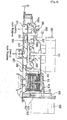
FIG. 7 is an exploded perspective view illustrating the construction of a dish washer according to the present invention. -
FIG. 8 is a side sectional view illustrating the flow of wash water during a washing operation of the dish washer shown inFIG. 7 . -
FIG. 9 is a side sectional view illustrating the flow of wash water during a draining operation of the dish washer shown inFIG. 7 . -
FIG. 10 is a detailed perspective view illustrating a housing assembly shown inFIG. 7 . -
FIG. 11 is an exploded view ofFIG. 10 . -
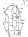
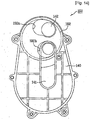
FIGs. 12 to 14 are plan views illustrating main flow channels controlled according to rotating positions of a flow channel control valve with a connection housing being removed. -
FIG. 15 is a reference view ofFIG. 12 , illustrating a plan view of the housing assembly with an upper housing being removed. - Reference will now be made in detail to the preferred embodiments of the present invention, examples of which are illustrated in the accompanying drawings.
- A dish washer according to the present invention includes a
sump 110 for receiving wash water, awashing pump 120 for pumping the wash water from thesump 110, ahousing assembly 100 havingflow channels cover 160 disposed to cover the upper end of thesump 110, afilter unit 170 disposed in thesump 110 through thecover 160 for filtering wash water having fallen to thecover 160 and introducing the filtered wash water into thesump 110, and adrainage pump 180 communicating with thefilter unit 170 for discharging filth filtered out by the filter unit and the wash water in thesump 110 to the outside at the time of a draining operation of the dish washer. - Preferably, a heater for heating the wash water is mounted in the
sump 110. The heater is not illustrated inFIG. 7 . Of course, the heater may be mounted at the bottom of a tub. - The
sump 110 has afilth receiving chamber 111 for receiving filth filtered out by thefilter unit 170. Thefilth receiving chamber 111 communicates with thedrainage pump 180. Preferably, thefilth receiving chamber 111 is mounted at the bottom of thesump 110. More preferably, thefilth receiving chamber 111 is disposed with an inclination toward thedrainage pump 180 such that the filth received in thefilth receiving chamber 111 can be easily discharged to thedrainage pump 180. - A
discharge flow channel 112 is formed such that thefilth receiving chamber 111 and thedrainage pump 180 communicate with each other. Preferably, thefilth receiving chamber 111 and adrainage chamber 113 communicate with each other through thedischarge flow channel 112. - The
drainage chamber 113 is formed in thesump 110 such that thedrainage pump 180 is mounted to thedrainage chamber 113. Thedrainage chamber 113 has a space where an impeller is disposed and a space into which filth is suctioned. - The
washing pump 120 includes awashing motor 121 for generating a driving force and animpeller 122 axially coupled to thewashing motor 121. Thewashing motor 121 is disposed in an upright driven structure in which a shaft of thewashing motor 121 is disposed approximately vertically. Preferably, thewashing motor 121 is an outer-rotor type brushless direct current (BLDC) motor. - The
drainage pump 180 includes a drainage motor (not shown) and an impeller (not shown). Thedrainage pump 180 is disposed in a horizontally driven structure in which a shaft of the drainage motor is disposed approximately horizontally. - The
housing assembly 100 includes alower housing 130, anupper housing 140 coupled to thelower housing 130 such that thelower housing 130 is covered by theupper housing 140, and aconnection housing 150 coupled to theupper housing 140 and a connection pipe connected to the washing arms. - The coupling of the upper and
lower housings pump compartment 131 in which theimpeller 122 constituting thewashing pump 120 is disposed, and a flowchannel control compartment 132, communicating with thepump compartment 131, in which a flow channel control valve is disposed. - The
upper housing 140 hasmain flow channels - The
connection housing 150 is coupled to theupper housing 140 such that themain flow channels upper housing 140 are covered by theconnection housing 150. Theconnection housing 150 is provided at the opposite ends thereof with coupling parts, which are coupled to connection pipes (not shown) connected to the washing arms. - The
lower housing 130 and theupper housing 140 are separately constructed as shown inFIG. 7 . Although not shown, however, thelower housing 130 and theupper housing 140 may be integrally constructed. - Preferably, the
pump compartment 131 and the flowchannel control compartment 132 are disposed on the same plane. This is because the height of thehousing assembly 100 is decreased, and the inner space of thesump 110 is increased. Also preferably, themain flow channels pump compartment 131 and the flowchannel control compartment 132. This is because the width of thehousing assembly 100 is decreased. - Preferably, the
cover 160, which covers thesump 110, is disposed with an inclination (seeFIG. 8 ) toward thefilter unit 170 such that the filth and the wash water having fallen to thecover 160 can easily flow to thefilter unit 170. - Preferably, a plurality of filter holes 161 are formed in the coyer 160 such that some of the wash water having fallen to the
cover 160 is filtered and directly introduced into the tub. More preferably, the filter holes 161 are disposed in thecover 160 at regions where thehousing assembly 100 is not located such that the contamination of the outer surface of the housing assembly due to the contaminated wash water is minimized. - The
filter unit 170 is constructed such that the lower end of thefilter unit 170 is open. The open lower end of thefilter unit 170 is coupled to thefilth receiving chamber 111. Preferably, the lower end of thefilter unit 170 is spaced a predetermined distance from the bottom of thefilth receiving chamber 111. For example, astep part 111a is formed at the upper end of thefilth receiving chamber 111 such that the open lower end of thefilter unit 170 can be supported by thestep part 111a. Thedischarge flow channel 112 is disposed below thestep part 111a of thefilth receiving chamber 111. Consequently, filth in thefilth receiving chamber 111 is discharged to thedrainage chamber 113 through thedischarge flow channel 112 without the interference of thefilter unit 170. - The
filter unit 170 includes anupper filter 176 fitted through thecover 160 for allowing the filth and the wash water having fallen to thecover 160 to pass therethrough and alower filter 171 coupled to theupper filter 176 and thefilth receiving chamber 111 for filtering out filth from the wash water. Thelower filter 171 has an open lower end. - Preferably, the
upper filter 176 and/or thelower filter 171 are detachably attached to thecover 160. Theupper filter 176 serves to filter out large particles of food wastes, and thelower filter 171 serves to filter out small particles of food wastes that have not been filtered out by theupper filter 176. - Preferably, the
upper filter 176 protruded a predetermined height from the top of thecover 160. This is because a user can easily pull out theupper filter 176 while holding theupper filter 176. Of course, it is not necessarily needed for the upper filter to protrude from the top of the cover so long as the user can easily pull out theupper filter 176 while holding theupper filter 176. - The flow
channel control valve 190 includes arotary shaft 191 coupled to a shaft of acontrol motor 200 and a flow channel opening andclosing plate 192 disposed at the upper end of therotary shaft 191, formed generally in the shape of a disc, and havingcommunication holes main flow channels closing plate 192 is rotated. The flowchannel control valve 190 is formed in the shape of a disc because themain flow channels channel control valve 190. Also, the flowchannel control valve 190 is constructed in a structure in which pumping pressure of thewashing pump 120 is applied upward. Consequently, when the pumping pressure is applied, the flowchannel control valve 190 is pressed against theupper housing 140, and therefore, the flowchannel control valve 190 is stably supported without shaking. - The communication holes 192a and 192b formed in the flow channel opening and
closing plate 192 have different areas. Consequently, it is possible to selectively control themain flow channels closing plate 192. - Now, the operation of the dish washer with the above-stated construction according to the present invention will be described. The dish washer performs sequentially or se lectively a preliminary washing operation, a main washing operation, a rinsing operation, a heating-rinsing operation, and a drying operation so as to wash dishes. Between the respective operations, a draining operation is performed. Hereinafter, the main washing operation and the draining operation will be described.
- First, the washing operation of the dish washer will be described in detail with reference to
FIGs. 8 ,11 , and12 to 14 . - When the
washing motor 121 is driven, theimpeller 122 is rotated. As a result, wash water is supplied from thesump 110 to thepump compartment 131 and the flowchannel control compartment 132. - At this time, the flow
channel control valve 190 is rotated such that themain flow channels channel control compartment 132. Here, the flowchannel control valve 190 may selectively open one of themain flow channels main flow channels channel control valve 190 may alternately open themain flow channels - When the
main flow channels channel control compartment 132 to the corresponding washing arms along themain flow channels - When the flow channel opening and
closing plate 192 of the flowchannel control valve 190 is positioned as shown inFIG. 12 , for example, the supplied to the upper washing arm 4 (seeFIG. 1 ) through themain flow channel 142. When the flow channel opening andclosing plate 192 of the flowchannel control valve 190 is positioned as shown inFIG. 13 , the wash water is supplied to the lower washing arm 5 (seeFIG. 1 ) through themain flow channel 141. When the flow channel opening andclosing plate 192 of the flowchannel control valve 190 is positioned as shown inFIG. 14 , the wash water is supplied to the upper andlower washing arms 4 and 5 through both themain flow channels - The dish washer according to the present invention is not provided with a sampling flow channel unlike the conventional dish washer. For this reason, all the pumped wash water is supplied to the washing arms. As a result, the amount of wash water injected to dishes is increased, and all the pumped wash water is substantially used to wash the dishes. Consequently, it is possible to apply a
washing pump 120 having a capacity smaller than that of the washing pump used in the conventional dish washer to the dish washer according to the present invention. Also, the consumption of wash water is considerably reduced. Furthermore, the wash water flow channel of the dish washer according to the present invention is simplified as compared to the conventional dish washer. Consequently, the flow channel resistance of the wash water is decreased, and therefore, the pumping efficiency is improved although the capacity of thewashing pump 120 of the dish washer according to the present invention is equal to that of the washing pump of the conventional dish washer. - The wash water injected from the washing arms washes dishes and falls to the
cover 160. At this time, the filth and the wash water having fallen to thecover 160 are introduced into theupper filter 176 because thecover 160 is inclined toward thefilter unit 170. Also, some of the wash water is directly introduced into thesump 110 through the filter holes 161 of thecover 160. - The
upper filter 176 filters out large particles of filth, and thelower filter 171 filters out filth that has not been filtered out by theupper filter 176. Consequently, only wash water containing no filth is introduced into thesump 110. - According to the present invention, it is not needed to periodically clean the
filter unit 170 during the washing operation of the dish washer unlike the conventional dish washer. Consequently, it is possible to provide the same injection amount of wash water as the conventional dish washer although a smaller amount of wash water is pumped than the conventional dish washer. In addition, the consumption of the wash water is considerably reduced. - The washing operation is performed for a predetermined period of time. As time passes, the amount of food wastes gathered in the
filter unit 170 is gradually increased. After the washing operation is completed, a draining operation of the dish washer is initiated. - Hereinafter, the draining operation of the dish washer will be described with reference to
FIG. 9 . - When the
drainage pump 180 is driven, the wash water in thesump 110 is introduced into thefilth receiving chamber 111 through thelower filter 171 due to the suction force of thedrainage pump 180. Then, the wash water is introduced into thedrainage chamber 113 together with the filth gathered in thefilth receiving chamber 111. At this time, the filth is smoothly introduced into thedrainage chamber 113 because thefilth receiving chamber 111 is inclined toward thedrainage chamber 113. Subsequently, the filth and the wash water in thedrainage chamber 113 are discharged to the outside through the drainage hose of thedrainage chamber 113. - According to the present invention, the drainage section (the flow channel between the
filth receiving chamber 111 and the drainage chamber 113) is considerably short as compared to the conventional dish washer. Consequently, hardly any of the filth is left in the drainage section. - Due to the aforesaid action, the filth gathered in the
filth receiving chamber 111 is completely discharged to the outside during the draining operation of the dish washer. - It will be apparent to those skilled in the art that various modifications and variations can be made in the present invention without departing from the scope of the invention. Thus, it is intended that the present invention cover the modifications and variations of this invention provided they come within the scope of the appended claims and their equivalents.
- The present invention provides a dish washer. More particularly, the present invention provides a dish washer having improved washing efficiency while being constructed in a compact structure. A general dish washer is an apparatus that injects wash water to dishes so as to wash the dishes, and dries and/or sterilizes the washed dishes. The dish washer according to the present invention includes a filter unit for filtering at least some of the wash water injected from a tub, fallen downward, and directed to a collection part of a sump.
- According to the present invention, it is possible to improve the washing efficiency of the dish washer, reduce the capacity of the washing pump, considerably decrease the amount of wash water substantially needed during a washing operation of the dish washer, reduce the consumption of wash water and power, reduce the flow channel resistance, considerably increase the wash water pumping pressure, simplify the structure of the drive unit, considerably reduce the height of the drive unit, increasing the inner space of the sump, and minimally prevent food wastes from being left in the sump during a drainage operation of the dish washer.
Claims (12)
- A dish washer comprising:a tub (1) for receiving dishes;an upper arm (4) and a lower arm (5) provided in the tub to spray water to the dishes;a sump (110) having a collection part that provides a space for collecting and storing wash water;an impeller (122) disposed above the collection part for pumping the wash water;a washing motor (121) fitted through a bottom of the sump (110) and axially coupled to the impeller (122) in the vertical direction;a filter unit (170) disposed at one side of the collection part for filtering at least some of wash water directed from the tub to the collection part of the sump (110);a filth receiving chamber (111) for receiving filth filtered out by the filter unit (170), anda housing assembly (100) having:a pump compartment (131) communicating with the collection part of the sump (110), the impeller (122) being located in the pump compartment (131),a flow channel control compartment (132) communicating with the pump compartment (131);a first flow channel (141) configured to connect the flow channel control compartment (132) with the lower arm (5);a second flow channel (142) configured to connect the flow channel control compartment (132) with the upper arm (4); anda flow channel control valve (190) provided in the flow channel control compartment(132) for controlling the flow channels (141, 142),
wherein the pump compartment (131) and the flow channel control compartment (132) are disposed on the same plane. - The dish washer according to claim 1, wherein a lower end of the filter unit (170) is spaced a predetermined distance from a bottom of the filth receiving chamber (111), and
wherein the filth receiving chamber (111) is disposed at the bottom of the sump (110), and the filter unit (170) is opened at the lower end thereof such that the filtered-out filth is directed to the filth receiving chamber (111). - The dish washer according to claim 2, wherein the bottom of the filth receiving chamber (111) is lower than a bottom of the collection part of the sump (110) and is inclined downward toward on opposite side of the collection part of the sump (110).
- The dish washer according to claim 1, wherein the filth receiving chamber (111) has a discharge flow channel (112) and wherein a bottom of the filth receiving chamber (111) is inclined downward toward the discharge flow channel (112).
- The dish washer according to claim 1, wherein the filter unit (170) is attachable and detachable.
- The dish washer according to claim 1, wherein the filter unit (170) comprises:a lower filter (171) having an open lower end and located in the filth receiving chamber (111); andan upper filter (176) for filtering out large particles of filth from wash water before the wash water is filtered by the lower filter (171).
- The dish washer according to claim 6, wherein the upper filter (176) is located in the lower filter (171) such that the upper filter (176) can be attached to and detached from the lower filter (171), and wherein the upper filter (176) is attached to and detached from the lower filter (171) through a cover (160) that covers the sump (110).
- The dish washer according to claim 7, wherein the lower filter (171) is blocked by the cover (160) so that the lower filter (171) is prevented from being detached through the cover (160).
- The dish washer according to claim 1, further comprising:
a cover (160) covering the sump (100), the cover (160) having a plurality of filter holes (161), through which some of the wash water from the tub is directed to the collection part without passing though the filter unit (170). - The dish washer according to claim 9, wherein the cover (160) has a through-hole in flow communication with the filter unit (170).
- The dish washer according to claim 10, wherein the cover (160) is inclined downward toward the through-hole.
- The dish washer according to claim 1, wherein the flow channel control valve (190) comprises:a rotary shaft (191) coupled to a shaft of a motor (200); anda flow channel opening and closing plate (192) connected to an upper end of the rotary shaft (191), formed in the shape of a disc, and serving to selectively open and close flow channels (141, 142) when the flow channel opening and closing plate (192) is rotated.
Applications Claiming Priority (3)
| Application Number | Priority Date | Filing Date | Title |
|---|---|---|---|
| KR1020050120627A KR101241870B1 (en) | 2005-12-09 | 2005-12-09 | dish washer |
| KR1020060091154A KR100800001B1 (en) | 2006-09-20 | 2006-09-20 | Dish washer |
| PCT/KR2006/005226 WO2007066968A1 (en) | 2005-12-09 | 2006-12-06 | Dish washer |
Publications (3)
| Publication Number | Publication Date |
|---|---|
| EP1973459A1 EP1973459A1 (en) | 2008-10-01 |
| EP1973459A4 EP1973459A4 (en) | 2016-12-21 |
| EP1973459B1 true EP1973459B1 (en) | 2020-09-09 |
Family
ID=38123066
Family Applications (1)
| Application Number | Title | Priority Date | Filing Date |
|---|---|---|---|
| EP06823933.4A Active EP1973459B1 (en) | 2005-12-09 | 2006-12-06 | Dish washer |
Country Status (3)
| Country | Link |
|---|---|
| US (1) | US8622065B2 (en) |
| EP (1) | EP1973459B1 (en) |
| WO (1) | WO2007066968A1 (en) |
Families Citing this family (3)
| Publication number | Priority date | Publication date | Assignee | Title |
|---|---|---|---|---|
| EP2468170A1 (en) * | 2010-12-21 | 2012-06-27 | Electrolux Home Products Corporation N.V. | Dishwasher spray arm support integral to sump structure |
| US10113654B2 (en) * | 2015-01-27 | 2018-10-30 | Haier Us Appliance Solutions, Inc. | Water diverter assembly for a dishwashing appliance |
| US9888827B2 (en) * | 2015-04-08 | 2018-02-13 | Haier Us Appliance Solutions, Inc. | Dishwasher appliance and a method for forming a unitary tub |
Family Cites Families (22)
| Publication number | Priority date | Publication date | Assignee | Title |
|---|---|---|---|---|
| GB942273A (en) * | 1960-12-16 | 1963-11-20 | Simplex Electric Co Ltd | Improvements relating to dish washing machines |
| FR1540245A (en) * | 1966-10-11 | 1968-09-20 | Candy Spa | Improvements in dishwashing machines and the like |
| FR2514082B1 (en) * | 1981-10-02 | 1985-12-06 | Esswein Sa | LIQUID PUMPING DEVICE AND APPARATUS PROVIDED WITH SUCH A DEVICE |
| DE8816597U1 (en) * | 1988-03-29 | 1989-12-21 | Licentia Patent-Verwaltungs-Gmbh, 6000 Frankfurt, De | |
| EP0383028A3 (en) * | 1989-02-14 | 1992-05-06 | Licentia Patent-Verwaltungs-GmbH | Dishwashing machine compromising an electro-mechanic reversing device |
| US5165433A (en) | 1991-08-19 | 1992-11-24 | Whirlpool Corporation | Soil separator for a domestic dishwasher |
| DE4344245C2 (en) * | 1993-12-23 | 1997-03-06 | Bosch Siemens Hausgeraete | Device on dishwashers for filtering the washing water |
| KR970010418B1 (en) | 1995-07-01 | 1997-06-26 | Lg Electronics Inc | Dishwasher |
| IT1276476B1 (en) * | 1995-07-06 | 1997-10-31 | Merloni Elettrodomestici Spa | DISHWASHER MACHINE WITH IMPROVED FILTERING SYSTEM AND RELATED FILTERING METHOD |
| KR970010418A (en) | 1995-08-24 | 1997-03-27 | 한승준 | Bumper of car |
| KR970010423B1 (en) * | 1995-09-19 | 1997-06-26 | 엘지전자 주식회사 | Method and processing for disposal garbage of a dishwasher |
| EP0842632B1 (en) | 1996-11-19 | 2006-02-08 | Whirlpool Corporation | Automatic purge filtration system for a dishwasher |
| DE19652231C2 (en) * | 1996-12-16 | 2000-03-23 | Whirlpool Co | Dishwasher with a lower and an upper spray arm and a circulation pump for the rinse water |
| KR100246388B1 (en) | 1997-05-12 | 2000-04-01 | 구자홍 | A device for filtering of table dishes washing-machine |
| KR100230787B1 (en) | 1997-08-20 | 1999-11-15 | 구자홍 | Device for discharging food wastes of a dishwasher |
| KR100269466B1 (en) | 1998-06-22 | 2000-12-01 | 윤종용 | Filter apparatus of dish washer with united pump |
| EP0990413B1 (en) * | 1998-09-29 | 2003-12-17 | CANDY S.p.A. | A method of filtering the washing and/or rinsing liquid in a dishwasher and apparatus for implementing the method |
| US6165433A (en) * | 1999-06-10 | 2000-12-26 | Praxair Technology, Inc. | Carbon dioxide recovery with composite amine blends |
| KR100529879B1 (en) * | 2002-11-28 | 2005-11-22 | 엘지전자 주식회사 | Dish washer |
| KR100488033B1 (en) * | 2003-07-31 | 2005-05-06 | 엘지전자 주식회사 | Control appatatus for washing flow of dishwasher |
| KR20050062145A (en) * | 2003-12-19 | 2005-06-23 | 엘지전자 주식회사 | Apparatus gathering water in the dishwasher |
| KR100606823B1 (en) | 2004-05-28 | 2006-08-01 | 엘지전자 주식회사 | apparatus of the dishwasher |
-
2006
- 2006-12-06 EP EP06823933.4A patent/EP1973459B1/en active Active
- 2006-12-06 WO PCT/KR2006/005226 patent/WO2007066968A1/en active Application Filing
- 2006-12-06 US US12/096,466 patent/US8622065B2/en active Active
Non-Patent Citations (1)
| Title |
|---|
| None * |
Also Published As
| Publication number | Publication date |
|---|---|
| EP1973459A1 (en) | 2008-10-01 |
| EP1973459A4 (en) | 2016-12-21 |
| WO2007066968A1 (en) | 2007-06-14 |
| US8622065B2 (en) | 2014-01-07 |
| US20090133724A1 (en) | 2009-05-28 |
Similar Documents
| Publication | Publication Date | Title |
|---|---|---|
| KR101016311B1 (en) | Washing machine | |
| KR101283781B1 (en) | Dish washer | |
| KR100606823B1 (en) | apparatus of the dishwasher | |
| EP1819263B8 (en) | Sump of dish washer | |
| JP4740247B2 (en) | dishwasher | |
| KR20070040879A (en) | A disc type valve for controlling the path of the washing water in a dish washer and a dish washer with it | |
| KR20100007340A (en) | Dishwasher | |
| KR200196942Y1 (en) | Dish washer | |
| EP1973459B1 (en) | Dish washer | |
| KR100686096B1 (en) | dish washer | |
| KR100640796B1 (en) | driving apparatus of the dishwasher | |
| KR100800001B1 (en) | Dish washer | |
| KR101241870B1 (en) | dish washer | |
| KR0146301B1 (en) | Dish-washer | |
| KR20140100072A (en) | Dish washer | |
| KR101356295B1 (en) | Sump for dish washer | |
| KR0122437Y1 (en) | A dish-washer | |
| KR100511967B1 (en) | Filter assembly of dish washer | |
| KR100457595B1 (en) | Filter assembly of dish washer | |
| KR0146299B1 (en) | Dish-washer | |
| KR0128906Y1 (en) | Dishwasher | |
| KR100269468B1 (en) | Passage structure of dish washer with united pump | |
| JPH11178773A (en) | Dish washer | |
| KR0146300B1 (en) | Dish-washer | |
| KR20060011279A (en) | A sub-filtering apparatus of a dish washer |
Legal Events
| Date | Code | Title | Description |
|---|---|---|---|
| PUAI | Public reference made under article 153(3) epc to a published international application that has entered the european phase |
Free format text: ORIGINAL CODE: 0009012 |
|
| 17P | Request for examination filed |
Effective date: 20080626 |
|
| AK | Designated contracting states |
Kind code of ref document: A1 Designated state(s): DE FR GB IT SE TR |
|
| DAX | Request for extension of the european patent (deleted) | ||
| RBV | Designated contracting states (corrected) |
Designated state(s): DE FR GB IT SE TR |
|
| RA4 | Supplementary search report drawn up and despatched (corrected) |
Effective date: 20161123 |
|
| RIC1 | Information provided on ipc code assigned before grant |
Ipc: A47L 15/42 20060101AFI20161117BHEP |
|
| STAA | Information on the status of an ep patent application or granted ep patent |
Free format text: STATUS: EXAMINATION IS IN PROGRESS |
|
| 17Q | First examination report despatched |
Effective date: 20180911 |
|
| GRAP | Despatch of communication of intention to grant a patent |
Free format text: ORIGINAL CODE: EPIDOSNIGR1 |
|
| STAA | Information on the status of an ep patent application or granted ep patent |
Free format text: STATUS: GRANT OF PATENT IS INTENDED |
|
| INTG | Intention to grant announced |
Effective date: 20200123 |
|
| GRAS | Grant fee paid |
Free format text: ORIGINAL CODE: EPIDOSNIGR3 |
|
| RAP1 | Party data changed (applicant data changed or rights of an application transferred) |
Owner name: LG ELECTRONICS INC. |
|
| GRAA | (expected) grant |
Free format text: ORIGINAL CODE: 0009210 |
|
| STAA | Information on the status of an ep patent application or granted ep patent |
Free format text: STATUS: THE PATENT HAS BEEN GRANTED |
|
| AK | Designated contracting states |
Kind code of ref document: B1 Designated state(s): DE FR GB IT SE TR |
|
| REG | Reference to a national code |
Ref country code: GB Ref legal event code: FG4D |
|
| REG | Reference to a national code |
Ref country code: DE Ref legal event code: R096 Ref document number: 602006059667 Country of ref document: DE |
|
| PG25 | Lapsed in a contracting state [announced via postgrant information from national office to epo] |
Ref country code: SE Free format text: LAPSE BECAUSE OF FAILURE TO SUBMIT A TRANSLATION OF THE DESCRIPTION OR TO PAY THE FEE WITHIN THE PRESCRIBED TIME-LIMIT Effective date: 20200909 |
|
| PGFP | Annual fee paid to national office [announced via postgrant information from national office to epo] |
Ref country code: IT Payment date: 20201210 Year of fee payment: 15 |
|
| REG | Reference to a national code |
Ref country code: DE Ref legal event code: R097 Ref document number: 602006059667 Country of ref document: DE |
|
| PLBE | No opposition filed within time limit |
Free format text: ORIGINAL CODE: 0009261 |
|
| STAA | Information on the status of an ep patent application or granted ep patent |
Free format text: STATUS: NO OPPOSITION FILED WITHIN TIME LIMIT |
|
| 26N | No opposition filed |
Effective date: 20210610 |
|
| GBPC | Gb: european patent ceased through non-payment of renewal fee |
Effective date: 20201209 |
|
| PG25 | Lapsed in a contracting state [announced via postgrant information from national office to epo] |
Ref country code: FR Free format text: LAPSE BECAUSE OF NON-PAYMENT OF DUE FEES Effective date: 20201231 |
|
| PG25 | Lapsed in a contracting state [announced via postgrant information from national office to epo] |
Ref country code: GB Free format text: LAPSE BECAUSE OF NON-PAYMENT OF DUE FEES Effective date: 20201209 |
|
| PG25 | Lapsed in a contracting state [announced via postgrant information from national office to epo] |
Ref country code: TR Free format text: LAPSE BECAUSE OF FAILURE TO SUBMIT A TRANSLATION OF THE DESCRIPTION OR TO PAY THE FEE WITHIN THE PRESCRIBED TIME-LIMIT Effective date: 20200909 |
|
| PG25 | Lapsed in a contracting state [announced via postgrant information from national office to epo] |
Ref country code: IT Free format text: LAPSE BECAUSE OF NON-PAYMENT OF DUE FEES Effective date: 20211206 |
|
| PGFP | Annual fee paid to national office [announced via postgrant information from national office to epo] |
Ref country code: DE Payment date: 20220615 Year of fee payment: 17 |