EP1973062A1 - Procédé et appareil pour créer et modifier des diagrammes Nodelink dans des systèmes informatiques PEN - Google Patents
Procédé et appareil pour créer et modifier des diagrammes Nodelink dans des systèmes informatiques PEN Download PDFInfo
- Publication number
- EP1973062A1 EP1973062A1 EP08151894A EP08151894A EP1973062A1 EP 1973062 A1 EP1973062 A1 EP 1973062A1 EP 08151894 A EP08151894 A EP 08151894A EP 08151894 A EP08151894 A EP 08151894A EP 1973062 A1 EP1973062 A1 EP 1973062A1
- Authority
- EP
- European Patent Office
- Prior art keywords
- node
- strokes
- hypotheses
- stroke
- link diagram
- Prior art date
- Legal status (The legal status is an assumption and is not a legal conclusion. Google has not performed a legal analysis and makes no representation as to the accuracy of the status listed.)
- Granted
Links
Images


Classifications
-
- G—PHYSICS
- G06—COMPUTING; CALCULATING OR COUNTING
- G06V—IMAGE OR VIDEO RECOGNITION OR UNDERSTANDING
- G06V30/00—Character recognition; Recognising digital ink; Document-oriented image-based pattern recognition
- G06V30/10—Character recognition
- G06V30/14—Image acquisition
- G06V30/142—Image acquisition using hand-held instruments; Constructional details of the instruments
- G06V30/1423—Image acquisition using hand-held instruments; Constructional details of the instruments the instrument generating sequences of position coordinates corresponding to handwriting
-
- G—PHYSICS
- G06—COMPUTING; CALCULATING OR COUNTING
- G06V—IMAGE OR VIDEO RECOGNITION OR UNDERSTANDING
- G06V30/00—Character recognition; Recognising digital ink; Document-oriented image-based pattern recognition
- G06V30/10—Character recognition
- G06V30/32—Digital ink
- G06V30/333—Preprocessing; Feature extraction
- G06V30/347—Sampling; Contour coding; Stroke extraction
-
- G—PHYSICS
- G06—COMPUTING; CALCULATING OR COUNTING
- G06V—IMAGE OR VIDEO RECOGNITION OR UNDERSTANDING
- G06V30/00—Character recognition; Recognising digital ink; Document-oriented image-based pattern recognition
- G06V30/40—Document-oriented image-based pattern recognition
- G06V30/41—Analysis of document content
- G06V30/414—Extracting the geometrical structure, e.g. layout tree; Block segmentation, e.g. bounding boxes for graphics or text
Definitions
- the present application is directed to the generation of electronically formed images, and more particularly to node-link type diagrams and more particularly concept maps which may be formed in a manner similar to those formed using a non-electronic whiteboard or pen and paper, but which further includes the ability to be electronically edited.
- Pen/stylus interfaces to computers hold the promise of applications that are as intuitive as a paper or whiteboard but with the power and functionality of editing, search, and other processing provided by computer applications.
- vertical surface and horizontal surface hardware has advanced considerably in the form of SMART Boards from SMART Technologies Inc. and the TabletPC Operating Systems from Microsoft Corporation, user interfaces remain awkward and unsophisticated.
- the concepts of the present application include, among others, designing and implementing an easy to operate, intuitive user interface for a particular target application, that of creating and editing node-link diagrams, which include the genre of concept maps, mind maps, and others.
- concept mapping software include MindJet from Mind Jet Corporation, SMART Ideas from SMART Technologies Inc., and FreeMind an Open Source mind mapping program written in Java, among others.
- a method and process provides structure recognition to a node-link diagram formed by a plurality of digital ink strokes drawn on a canvas of an electronic device by an input device.
- the method and process include grouping related strokes into multiple hypotheses reflecting structure interpretations of the strokes in a group. Confidence scores are computed for the multiple hypotheses based on local evidence regarding the strokes of the stroke groups and surrounding strokes. Constraints are applied among the hypotheses, and a collectively high scoring assignment of accept/reject values of the hypotheses are determined under the applied constraints.
- the hypotheses with collectively high scoring assignments are accepted as a representation of the node-link diagram, where structure information is provided to the strokes of the node-link diagram, making the node-link diagram electronically editable.
- the digital ink strokes are one of (i) strokes of the node-link diagram, or (ii) strokes that are not part of the node-link diagram.
- the node-link diagram includes both text and graphics.
- a computer readable medium is provided that has computer executed instructions for performing steps comprising:
- Figure 1 illustrates the concepts of the present application within a stylus/pen computing environment
- Figure 2 provides a high-level view of the processes used to initiate the concepts of the present application
- Figure 3 is an architectural relationship between the graphical user interface module and the recognition module of the present application
- Figure 4 sets forth a high-level flow diagram for the operational aspects of the present application
- Figure 5 is a screen snapshot of the node-link diagram program of the present application.
- Figure 6 provides a summary of the various instructions/operations for the program (e.g ., ConceptSketch) of the present application;
- Figure 7 is a flow diagram for the user action protocol for the ConceptSketch program of the present application based on the inferred-mode protocol;
- Figure 8 depicts the tapping operation and the ambiguity associated with such selection
- Figure 9 elaborates on the relationship between the GUI module (layer) and Recognition Module (layer);
- Figure 10 sets forth the more detailed view of the pre-interpret operation of the present application.
- Figure 11 sets forth the grouping operation of Figure 10 in greater detail
- Figure 12 sets forth the various methods of the interface between the GUI and Recognizer modules
- Figure 13 shows the ontology for the node-link diagram structure to which the concepts of the present application are directed;
- Figure 14 illustrates the multiple or forest of structure hypotheses which are obtained during the structure recognition process
- Figure 15 sets forth a successful node-link structure hierarchy obtained by the structure recognition processing
- Figure 16 illustrates the wedge hypotheses obtained by operation of the present application on a node-link diagram
- Figure 17 illustrates the arrowhead hypotheses obtained in a node-link diagram
- Figure 18 depicts closed-path object hypotheses obtained for a node-link diagram
- Figure 19 depicts curvilinear connector hypotheses obtained by the system for a node-link diagram
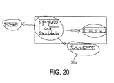
- Figure 20 depicts graph-node hypotheses obtained by the present application for a node-link diagram
- Figure 21 illustrates graph-link hypotheses obtained by the present application for a node-link diagram
- Figure 22 is a flow diagram associated with operation of the selectables list
- Figure 23 is a hierarchical node diagram depicting the support context scores and intrinsic scores found during the structure recognition operations
- Figure 24 is an example of a hierarchical node lattice and representation of support relations in a support table obtained during the structure recognition operations;
- Figure 25 sets forth a logic diagram of a main loop for a depth-first search optimization using non-overlapping support constraint algorithms
- Figure 26 is an illustration of how states (A, B, C) keep track of node search in a search tree by directing a tree pointer.
- Figure 27 expands on the steps in a processing for the last group node in a node search
- Figure 28 sets out a more detailed flow diagram for the veto-conflicting-support-node operation in the structured recognition operations
- Figure 29 sets forth an un-veto-conflicting support node operation during the structured recognition operations.
- Figure 30 illustrates operations of the recognition module that modify hypotheses lattices.
- the following describes methods and systems for interactive creation and editing of node-link diagrams with stylus/pen computing systems, at times referred to herein as the ConceptSketch program or process which employs a User Interface (Ul).
- the Ul operates as an extension to writing on an electronic whiteboard, graphics tablet, digital paper, or other flat surface or electronic canvas.
- the markings are covertly interpreted as the nodes, links, and textual labels of a node-link diagram, such as a concept map.
- the recognized structure subsequently enables simple tap selection of meaningful objects, and incremental, user-directed, reversible beautification/formalization operations.
- the UI requires no learning of arcane gestures, no requirement to set command and/or draw modes, and no need for toolbars or palettes.
- This UI design employs a novel architecture which divides the complex below-the-surface work of the Ul into Graphical User Interface (GUI) and Recognition modules (also called layers or processes). Digital ink strokes are maintained in parallel between the GUI and Recognition modules, and communication between modules takes place primarily in terms of Stroke IDs and XML strings.
- GUI Graphical User Interface
- Recognition modules also called layers or processes.
- Digital ink strokes are maintained in parallel between the GUI and Recognition modules, and communication between modules takes place primarily in terms of Stroke IDs and XML strings.
- Realization of the UI design also depends on the ability of the Recognition module to interpret hand-drawn text and graphics. It is well known that this is a very difficult problem in the Artificial Intelligence and Computational Vision fields, due to richness and complexity of the diagram domain, imprecision on the part of human users, and ambiguity in the interpretation of constituent digital ink strokes.
- the present concepts disclose approaches to solve the problem for the node-link diagram interpretation task.
- This application also describes the ontology of objects, algorithms for building a lattice of hypotheses, and constrained search processes to search the hypotheses space for the optimal, near-optimal, or desired obtainable global interpretation.
- the present concepts are directed to methods and systems for intelligent node-link diagram creation and editing, where the intelligent portion of the system covers the added functionality obtained by recognition of the structure of the diagrams, either independently or bundled together. Also, while the following generally discusses node-link diagrams, the present concepts provide particular benefits to the creation and editing of concept maps.
- Concept maps are special forms of node-link diagrams which are composed of nodes and links used to graphically represent information.
- concept mapping nodes are defined as the representation of data that represent a concept, item or question.
- Nodes can have a wide number of non-exclusive attributes to represent the data, such as labels, colors, or shapes, among others.
- Links are also used to represent data by depicting relations among concept nodes. Often, they have an additional characteristic in that they relate to data representations by identifying direction, for example, with a termination symbol such as an arrow symbol.
- labeled links explain the relationship between the nodes, and arrows or other terminators can describe the direction of the relationship, allowing the user to read the concept map.
- Directional links are, however, optional in concept maps and other node-link diagrams.
- links may have termination symbols on either end, or may not have any termination symbols.
- links and nodes can be either labeled or unlabeled. At times, simply the existence of a directed or undirected link is sufficient to express a relationship, while in other situations, the label will provide more details of a relationship.
- FIG. 1 illustrated is an environment or system 10 within which the concepts of the present methods or systems may be implemented.
- An electronic display 12 is in operative communication with a computing device 14.
- the display 12 and computing device 14 are configured to operate with an electronic stylus or pen 16, or additionally/alternatively a keyboard 18 or mouse 20.
- the computing device 14 includes memory and processing capabilities sufficient to store and operate the ConceptSketch program when appropriate inputs are received by the computing device 14. While various ones of the components described above are shown wired to each other, it is to be appreciated the system may act in a wired or wireless environment.
- the electronic display 12 and computing device 14 are configured to form a writing area such as a canvas 22 on which a user operates the stylus or pen 16 to create a node-link diagram 24 in accordance with the concepts of the present application.
- the canvas is intended to represent a region of the electronic display, which permits drawing or writing directly onto the surface of the display by generation of electronic ink by the stylus or pen 16.
- a device e.g., a graphics tablet
- a device that is written upon in order to enter the ink strokes, may be separate and apart from the display on which a user or others view the diagram.
- Hand-drawn node link diagram 24 contains four nodes 26a-26d, and five links 28a-28e, where closed graphic shapes (e.g., 26a and 26c) represent nodes; curved linear arcs ( e.g ., 28a-28e) represent links linking two nodes; text alone ( e.g ., 26d) may also be used to represent nodes; and text may be included within nodes ( e.g ., 30a).
- Text (30b-30c) can be labels of links, and arrows or other shapes 32a are used to identify termination of links in the node-link diagram as will be expanded upon below. It is also to be understood that not every stroke on a canvas must be part of the node-link diagram. For instance, ink stroke 34 may be interpreted by the present system and method as an "other" type of stroke or extraneous material.
- FIG. 2 illustrated is a high-level diagram 38 that describes an embodiment of the initialization operations 40 used to arrange the environment 10 for operation of the present system and method.
- These operations include a canvas creation initialization process 42; a Graphical User Interface (GUI) initialization process 44; an unprocessed strokes queue initialization process 46, a processed (or interpretation) strokes queue initialization process 50, as well as a recognition initialization process 48.
- GUI Graphical User Interface
- an unprocessed strokes queue initialization process 46 a processed (or interpretation) strokes queue initialization process 50, as well as a recognition initialization process 48.
- a wait state for user input such as an electronic pen stroke
- the system can operate in realtime as input is provided.
- the system can be designed to read ink strokes from a file of stored ink strokes, and thus realtime input operation is not a mandatory feature of the system.
- initialized processes 42-50 are de-synchronized from each other, such that they may be run as separate asynchronous threads within an operating system. This de-synchronization provides flexibility to the ConceptSketch program, and the ability for realtime response to writing while executing recognition processes as a background job.
- FIG. 3 illustrates a system architecture overview of the User Interface (Ul) 60, showing the relationship between GUI module 62, and Recognition module 64.
- the GUI module 62 is designed to handle input and display of digital ink strokes on the canvas, and the majority of the command interaction logic such as detecting encircling strokes and presenting and handling pop-up buttons.
- the GUI module 62 may be implemented in a variety of programming language and run-time environments, which may be different from the environments of the Recognition module 64, which includes a ConceptSketch recognizer (which may run in a , JVM - Java Virtual Machine) 64a, unprocessed strokes queue 64b, a processed (interpretation) strokes queue 64c, a formal interface 64d and access to a handwriting recognizer 64e.
- ConceptSketch recognizer which may run in a , JVM - Java Virtual Machine
- the Recognition module 64 is designed to interpret the user's input markings in terms of words, lines, columns of text, graphic objects and the model of node-link diagrams.
- the unprocessed strokes queue 64b is designed to receive electronic ink stroke information from GUI module 62, and the processed strokes queue 64c will provide processed stroke information from the Recognition module 64 to the GUI module 62.
- Formal interface 64d provides a path for interaction between the two modules.
- the handwriting recognizer in one embodiment may be handwriting software from Microsoft Corporation, such as may be used in its TabletPC operating systems.
- the GUI module is waiting for an event, such as an input (e.g. , a stroke) from the stylus or pen.
- an event such as an input (e.g. , a stroke) from the stylus or pen.
- the GUI module receives an ink stroke 74.
- the GUI module determines whether the ink stroke is: (i) an inking action, (iii) a tap action, (iii) an encircling action, or (iv) a scratch-out action 76.
- the inking action is interpreted as an act of writing or drawing on the canvas.
- a tap action is the movement of the stylus or pen onto a spot of the canvas and is intended to select or deselect the item which is tapped. Alternatively, when an item is selected, a tap in the background of the canvas acts to deselect that item.
- the encircling action is an ink stroke that encircles other existing ink strokes or other items and may be an inking action or selection gesture.
- the scratch-out action is an act of writing or drawing in a zig-zag, back-and-forth, X-ing out, or other "delete" type action over existing ink strokes or other items. As part of the process, the encircling and scratch-out actions will be determined to be either inking actions or selection gestures.
- Step 78 an initial decision is made as to whether the stroke is definitely an inking action (i.e., intended to be writing or drawing).
- Step 78 determines that a stroke is definitely an inking action if one of the following is true: (i) the stroke's length is less than a predetermined size and there are no objects on the canvas nearer than a predetermined distance to the stroke and the stroke begins within a predetermined time after the end (pen-lift) of the previous stroke; (ii) the stroke does not form a closed path shape and does not form a zig-zag (scratchout) shape; (iii) the stroke forms a closed path shape that does not encircle any other material on the canvas; or (iv) the stroke forms a zig-zag (scratchout) shape but no objects on the canvas are within a predetermined proximity to the stroke.
- step 80 determines whether the stroke is a tap action, or else one of an encircling action, scratch-out action, or inking action.
- Step 82 determines the stroke is a tap action if the stroke's length is less than a predetermined threshold, the stroke begins more than a predetermined time after the end (pen-lifting) of the previous stroke, and if at least one object on the canvas is within a predetermined distance of the stroke's location.
- step 82 If in step 82, the action is determined to be a tap action, the process moves to step 84, which sends a command or signal to the Recognizer module to perform the operation associated with the corresponding tap select command (not shown in this figure). On the other hand, at step 82, if it is determined the action is not a tap action, processing proceeds to step 86. Step 86 determines whether the stroke is possibly an encircling select gesture or possibly a scratch-out delete gesture, based on the stroke's shape.
- step 90 the system is positioned to collect user actions which will clarify the situation. More particularly, in step 92, if the user places the stylus or pen to the "Select?'" button associated with the encircled information, the system moves to step 94, where an encircle select command is provided to the Recognition module (not shown in this figure). This indicates that the encircling action is a selection gesture.
- the Recognition module will determine what is selected.
- the Recognition module could select what was encircled or covered by a scratch-out, or it could interpret the intent of the gestures in terms of recognized strokes (or other items) that were or were not literally covered.
- the user does not perform a tap select operation, but rather places the pen down in the background of the canvas, the system interprets this as indicating the encircling information is intended to be a word or drawing, and the stroke is added to the canvas as digital ink at step 80.
- step 98 the system is positioned to collect user actions which will clarify the situation. More particularly, in step 100, if the user places the stylus or pen to the "Delete?" button associated with the objects in close proximity to the stroke, the system moves to step 102, where a scratchout select command is provided to the Recognition module (not shown in this figure). This indicates the inking action is a deletion gesture and the items covered by the gesture are deleted from the Recognition module and the UI canvas.
- step 100 the user does not perform a tap select operation on the "Delete?" button, but rather places the pen down in the background of the canvas, the system interprets this as indicating the scratchout stroke is intended to be a word or drawing, and the stroke is added to the canvas as digital ink at step 80.
- step 80 When an action is determined to be an ink stroke at step 80, the process places the stroke --- identified as inking actions--- on the unprocessed (raw) strokes queue.
- step 104 a pre-interpret or process command is sent to the recognizer module to perform "pre-interpret" and/or "process” operations on the strokes in the unprocessed strokes queue.
- the operations performed in steps 72 through 104 may be considered to take place in the GUI module (e.g., 62 of Figure 3 ).
- the Recognition module will undertake the pre-interpret and/or process commands. However, as the GUI module and Recognition module are temporally de-synchronized in their operations, additional strokes may be placed on the canvas, during this time, and the GUI module will continue to operate independently.
- step 106 the Recognition module is waiting for the "pre-interpret" or "process” commands to be issued by the GUI module. Once received, operation of the Recognition module moves to a decision block 108, wherein the process moves to step 110 when it is determined the command is a pre-interpret command. At that point, the raw strokes from the unprocessed strokes queue are broken up at the corners into fragments (This operation is for more complex strokes. For simple strokes, which have no corners, this operation is not necessary).
- the stroke fragments and/or simple strokes are provided with identification information (IDs) and are then placed on the processed strokes queue 112.
- IDs identification information
- the GUI layer 62 moves to step 116 and replaces the raw strokes with the stroke fragments from the processed strokes queue.
- the GUI adds all the stroke fragments to a table or other memory device along with the stroke IDs. Hence, once put in the table or other memory device, the stroke fragments replace the raw strokes on the canvas (such replacement will be imperceptible to a user).
- both the information of the points (i.e., x-y positions and time) making up the stroke fragments, along with the IDs, are passed to the GUI module.
- the Recognizer module and the GUI module has the same stored information regarding the strokes.
- step 106 the process moves to step 114 where structured recognition operations are performed on the processed fragmented strokes. Thereafter, these structured processed fragments may, in one embodiment, be maintained in the Recognition module until strokes (e.g ., in the form of objects) are selected for some sort of command operation (e.g ., formalize, move, etc.).
- strokes e.g ., in the form of objects
- some sort of command operation e.g ., formalize, move, etc.
- Flowchart 70 outlines the process of determining whether a stroke is an inking action, a tap action, an encircling action or a scratch-out action, and the operations taken following such a determination.
- Employing the above process permits a user to create node-link diagrams as intuitively as using a paper or whiteboard, but with the power and functionality of computer applications.
- Figure 5 depicts a screen shot of a node-link diagram 120 generated using the concepts of the present application , where the user has selected and formalized certain parts, i.e., "taste" within the oblong 122 and the word "texture" 124 of the hand-drawn concept map ( i.e., the node link diagram).
- the node-link diagram has been automatically recognized by the system as having four graph nodes and three graph links.
- pre-interpret and/or process operations can also be undertaken by having the Recognition module poll the unprocessed and processed queues to determine if there are any strokes on the queues for which the above operations are to be performed.
- the system can also be designed to undertake multiple pre-interpret operations and then process those pre-interpreted strokes as a group, or the system can be arranged so the pre-interpret operation is directly followed by a process operation of the same stroke.
- the system described herein has the look and feel of a normal whiteboard.
- the program can be used as a simple walk-up and draw/write device with no formal training. Then, with just a minimal amount of instruction the user gains access to the power of a behind-the-scenes recognition engine that enables them to easily manipulate anything they may have drawn that resembles a node-link diagram in terms of its meaningful parts and relations.
- Users can select node objects, link objects, or their constituent graphical figures and textural labels by a standard Tap gesture. Or, users can select by the standard encircling gesture. Once selected, users can manipulate these objects, by changing color, moving and resizing them, and most notably by beautifying or formalizing them. Users can also delete by the standard scratch-out gesture.
- Figure 6 presents an example instruction sheet 130 illustrating the small number of instructions 130a-130f which a user needs to know to operate the UI for the system of the present application.
- a solution to the mode problem presented here uses, in one embodiment, an Inferred Mode protocol and a tap cycle selection technique for mixed digital ink input and selection in pen/stylus systems.
- the user is free to perform marking or selection gestures without prior specification of mode.
- the system attempts to infer user intent from context. If the intent is ambiguous, then a mediator button appears which the user may either tap or ignore.
- pen input is registered as digital ink as it is drawn on the canvas.
- Certain pen input can also be interpreted as being intended by the user to select some subset of digital ink markings. For example, tapping on an object, encircling it, or scratching it out are all forms of input that are natural for initiating selection and deletion operations.
- tapping on an object, encircling it, or scratching it out are all forms of input that are natural for initiating selection and deletion operations.
- a choice is provided to the user in the form of the pop-up button or icon.
- Drawing a closed empty circle is clearly a drawing action, but drawing an encircling around some existing digital ink is ambiguous.
- the user could be attempting to select the enclosed material, or they could simply be drawing a circle around it.
- a pop-up button is shown saying "Select?" If the user taps the pop-up button then the material is displayed in highlight mode to show it is selected, and locally icons for resizing and performing other operations are overlain on the canvas. Or, the user is free to ignore the pop-up button and keep drawing, in which case the encircling will be registered as digital ink.
- Interaction Flow Diagram 140 of Figure 7 An example of User Interaction with the UI is represented by Interaction Flow Diagram 140 of Figure 7 .
- Squared boxes represent computer display of information to the user (i.e., square boxes are computer actions associated with information displayed to the user 142a-142d).
- Rounded boxes represent user actions, including: drawing strokes; drawing an encircling gesture; tapping on strokes or formal graphic objects to select objects or cycle through selections; tapping in the background to deselect; tapping on the pop-up "Select?" button; tapping on the pop-up command icon; and choosing an item in the pop-up command menu, 144a-144h.
- Decision diamond 146 represents the processes' determination whether the ambiguous encircle actions can be disambiguated on the basis of context. Circles 148a-148d represent choices for the user.
- the system of the present application exploits an alternative structure selection protocol (e.g., the tap cycle select technique) which employs a lattice hierarchical structure, such as described in U.S. Patent No. 6,903,751 , entitled “System And Method For Editing Electronic Images,” by Saund et al.; and U.S. Patent No. 5,553,224 , entitled “Method For Dynamically Maintaining Multiple Structural Interpretations In Graphics System", by Saund et al..
- the first tap causes the most likely selectable object supported by the digital ink object under the tap to be selected. Which alternative is considered most likely among the possible choices, and therefore displayed first, is a design parameter that can be tuned in the system. For concept maps, nodes and links are considered the most salient objects. Repeated taps in approximately the same place cycle through other alternatives. Once some material has been selected, tapping over other markings causes their respective structure objects to be added to the highlighted selection.
- any given piece of digital ink may be part of multiple structured objects in the domain of node-link diagrams (e.g ., concept maps).
- a pen tap on stroke 152 could indicate the letter "T” 154, the word “Today” 156, or the node in the concept map consisting of the word “Today” and its enclosing rectangle 158.
- the user can use repeated tapping to obtain the desired selection. More particularly, the tap cycle select technique is used to select the intended strokes.
- Correction of erroneous handwriting recognition is initiated by scratching out or otherwise selecting incorrect letters, words, or blocks of text. These are deleted and the next text entry is mapped to the location where the deleted text had been located. In some cases, previous alternative handwriting recognition results are displayed in a menu for the user to select.
- system architecture of the present application is described from three perspectives: (i) the functional organization of system modules, (ii) specification of the functions performed by each module, and (iii) the interfaces governing communication between the modules.
- GUI module 62 handles input and display of digital ink strokes on the canvas, and most of the command interaction logic of the system such as detecting encircling strokes, and presenting and handling pop-up buttons (as illustrated in Figure 7 ).
- the GUI module 62 may be implemented in a different programming language and runtime environment than the Recognition module 64, as long as they can communicate.
- the Recognition module 64 handles interpretation of the user's input markings in terms of words, lines, and columns of text, graphic objects, and the document model of node-link diagrams.
- a specific purpose of the Recognition module is that it provides the system functionality by (i) providing intelligent selection via tapping, encircling and scratchout operations; (ii) formalizing of items; (iii) the moving of objects so links will follow the nodes they point to; and (iv) permit the exporting of the node-link (e.g ., concept map) structure.
- the two layers can run as different threads and therefore asynchronously in the operating system.
- the GUI module 62 is designed to be fast and responsive to user input, and display digital ink promptly as events are received from the pen, stylus, or mouse.
- the Recognition module 64 can perform computationally intensive operations that may take considerable time to complete (on the order of several seconds).
- Communication between the two layers is of at least two forms.
- Process flow diagram 180 of Figure 9 elaborates on the passing of stoke data between the modules of Figure 3 .
- the original input strokes drawn or written by users must be broken into smaller fragments. This may not be done in real time as the user is writing, but with some delay.
- the stroke queues are used to hold raw and fragmented strokes until their respective recipient processes are ready to accept them.
- the UI layer provides raw strokes 182 to the unprocessed (raw) strokes queue. These strokes are provided to the Recognition layer for a stroke fragmentation process 184.
- the stroke fragmentation process fragments the strokes 186 and places these strokes on a processed stroke queue 188, which may be then used to replace the existing stroke information on the canvas, with the processed fragmented strokes 190.
- the operations up to step 190 occur relatively in realtime. This permits a user to continually draw on the canvas without waiting for system updates or delays.
- this portion of the system does not provide "intelligence", to the image on the canvas ( i.e ., it does not allow rough sketches to be formalized, objects to be moved, colored, cut, etc.).
- the fragmented strokes 186 shown on the Recognition layer side of the figure (in the system they are held in one of the strokes queues) have structure recognition operations 192 applied thereto. These structure recognition operations can occur in a temporally desynchronized manner from the writing and drawing steps undertaken by a user.
- the processed fragmented strokes 190 may be displayed on the canvas at the same time the same fragmented strokes in the Recognition layer are undergoing structure recognition operations, whereafter, the fragmented strokes are provided with formal objects and relationships 194.
- the process of breaking raw strokes into fragments and establishing a synchronized list of stroke fragments in the GUI and Recognition modules as performed by the "Pre-Interpreting" command is detailed in flow diagram 210 of Figure 10 .
- the Pre-Interpret operation includes logic for creating and updating initial hypotheses in the Recognition module about which groups of strokes form handwritten words, or "Text Objects".
- the GUI module initiates a new "PenPath" object. As the pen is dragged, points are added to the path. When the pen is lifted the GUI module determines whether the PenPath object is a Tap or a Stroke. If it is a Stroke, the GUI module determines whether the stroke encircles other strokes. If not, the PenPath object is assigned an ID (the raw-penpath-id) and is placed on the unprocessed (raw) strokes queue 212.
- ID the raw-penpath-id
- the Recognition module is invoked in a separate thread. In one embodiment, if it is not already running the Recognition module is started after the pen is lifted after drawing a stroke. Because recognition can be time-consuming, unprocessed strokes can be in the queue, and in this situation the Recognition module will take them in larger but less frequent reads of the unprocessed strokes queue. Alternatively, the Recognition module may be in a constant gathering configuration, where it will be constantly testing to see if there are any unprocessed strokes, and will immediately act to process such strokes.
- the Recognition module removes strokes from the unprocessed stroke queue 214 and breaks the strokes into smaller fragments, which may be called “finished strokes” or “fragmented strokes” 216.
- a multi-scale corner detection algorithm is applied to determine where the breaks should be. Such algorithms are well known in the art and any of those known may be used for this process.
- the finished strokes maintain pointers to the original raw "parent" stroke that each was derived from. Each finished stroke is assigned a unique ID.
- the new finished strokes are placed on the processed (finished) strokes queue 218. They are also stored in a copy of the canvas maintained in the Recognition module, and in this state are called "Atoms", stored in an Atom list 220.
- the GUI process selectively queries the processed strokes queue. If any processed strokes are present, then it removes these strokes' parent raw strokes from the canvas and replaces it with the processed smaller finished strokes.
- the GUI module and Recognition module each have identical copies of finished (processed) strokes and their associated shared IDs.
- the IDs provide means for the two modules to communicate about strokes with each other, via stroke IDs.
- the Recognition module Along with breaking raw strokes into fragments, in the Pre-Interpret stage the Recognition module also forms groupings 222 of finished strokes that could belong to the same handwritten word. These are Text Object hypotheses and are stored in a Text Object hypothesis list 224. Methods for determining the grouping of digital ink strokes into words are known in the art and available in the literature. In general, because of the variability of human writing, no hard-and-fast rules can unequivocally form groupings that correspond to human interpretation. Instead, multiple hypotheses will be generated.
- the process works to determine whether the new stroke clearly belongs to an existing Text Object, clearly does not belong to an existing Text Object, or is ambiguous. If the stroke is ambiguous then two new hypotheses are created, one in which the stroke is added to the pre-existing Text Object hypothesis list 224, and one in which the stroke spawns a new Text Object, which will be placed in a newly touched (also at times referred to herein is spatially transformed)Text Object list 226.
- This process can potentially lead to an explosion of hypotheses so the implementation of this strategy must be handled with care.
- There are a number of procedures to limit the hypothesis for example, a straightforward manner would be to simply include a maximum allowable hypotheses value. Alternatively, a time limit for hypotheses generation may be included. These are just two of any number of hypotheses restrictions which could be included in the present system.
- Figure 11 illustrates in more detail the grouping of strokes with Text Object hypotheses, as introduced in block 222 of Figure 10 .
- the new finished stroke 214 is investigated to determine geometric compatibility of the stroke with the existing Text Object hypothesis 230, by supplying the stroke to a decision block 232, which determines if the stroke is "very compatible", "somewhat compatible” or "not compatible". When it is found to be "very compatible” the process moves to add the stroke to the existing Text Object hypothesis 234, and it is then added to a list 236 (or 224 of Figure 10 ). If in step 232 the stroke is found to be "somewhat compatible", the process will duplicate the existing Text Object hypothesis 238, add the stroke to the duplicate hypothesis list 240, and also add it to the existing list 236. When the determination is that the stroke is "not compatible” the process spawns a new Text Object hypothesis 242, and it is added to the list of all hypotheses 236.
- the GUI and Recognition modules are designed to work with each other through an Interface protocol.
- the protocol is called IConceptSketchRecognizer (I stands for the Java Interface declaration).
- the primary job of the Recognizer is twofold: first, help the GUI decide what objects to display as selected when the user performs selection gestures, and second, provide formalized or informal objects to display when the user issues Formalize or Roughen commands.
- a number of ancillary functions are also provided.
- IConceptSketchRecognizer interface 250 implemented by the Recognizer module is shown in Figure 12 . These are all methods to be implemented by any Recognition module. These methods are called by the GUI. Some of the methods return values, others operate by side effect (like removing and placing strokes on queues).
- GUI module collects digital ink from the pen input device, it is represented on the GUI side as "raw strokes". These are placed on the raw-stroke-queue.
- Pre-Interpreting Strokes (266): prelnterpretStrokeslnlnputStrokeQueue();
- the Recognition module implements a message passing method called prelnterpretStrokeslnlnputStrokeQueue(); This may be called deliberately by the GUI, or it may be invoked automatically through a scheduler.
- the Recognition module pre-interpretation process removes strokes from the raw-strokes-queue and places strokes on the processed (finished) strokes queue. These finished strokes may be identical to raw strokes obtained from the raw strokes queue, or they may be new strokes which are fragments of the raw strokes. Typically the fragments will be due to breaking the original raw strokes at corners.
- the GUI module continually tests for finished strokes on the processed (finished) strokes queue. When it finds finished strokes there, it removes them from the queue and replaces any obsolete raw strokes with new finished strokes. All raw and finished strokes maintain internal IDs which enable the GUI and Recognizer modules to keep track of them.
- the GUI module and Recognition module maintain separate, synchronized copies of the finished strokes, using hash tables or other known techniques to maintain the cross-references.
- the Recognition module implementation of structure recognition is imperceptible to a user. Its only visual effect will be reflected when objects are selected and formalized.
- the selectTap method is called by the GUI to tell the Recognition module that the user has tapped the pen at a certain location on the canvas, indicated by the x-y location of Point p.
- the GUI decides what strokes the user intended to select, and returns an array (e.g ., int[] array) with the IDs of these strokes. Under the Inferred Mode protocol, this decision is based on any stroke located under or in the near vicinity of Point p, and the recognized groups that this stroke belongs to.
- b_last_operation_was_selec_objects contributes to the intuitive selection logic of the Inferred Mode protocol. When true, it informs the Recognition module that the user is selecting multiple objects by sequential tapping, depending on the location of the tap point, and therefore the IDs of already-selected strokes should be included in the list of selected strokes returned by the call. If false, it indicates that the IDs of currently selected strokes should be discarded before building the list of selected strokes to be returned.
- the selectPath method allows selection of strokes by drawing a closed path around them. The decision about whether a closed path stroke is ambiguous by virtue of enclosing other strokes, and therefore requiring a "Select?" mediator under the Inferred Mode protocol, is left to the GUI.
- the select Path method is only used to cause the enclosed strokes to be considered selected by both the GUI and Recognition modules. The GUI will typically render the selected strokes as highlighted in some fashion. Deleting Strokes (256): public int[] deleteStrokes(int[] stroke-ids);
- deleteStrokes is called by the GUI to cause certain strokes to be removed from the canvas.
- the Recognizer module must deal with deconstructing whatever recognized structure these strokes participated in.
- the return int[] is the IDs of strokes deleted from the canvas, and should be identical to the int[] stroke-ids passed.
- the scratchOut method is called by the GUI when it suspects the user has drawn a stroke intended to be a scratch-out gesture (typically a zig-zag).
- the Recognition module is then required to determine exactly which strokes the user probably intends to delete, as determined by the path of the scratch-out gesture and the structural groups the recognition algorithms have constructed.
- the argument, PenPath scratchout-path is a listing of points (including their time stamps) of the gesture. The smarter the recognition module is, the better it will be at recognizing the user's intent even when they have drawn ambiguous scratch-out gestures.
- the return value is a data structure containing the stroke IDs (e.g .,an int[] array). Normally the GUI should display these as highlighted along with a confirmation button saying something like, "Delete?". If tapped on, the GUI will then pass these stroke IDs to the Recognizer as arguments to the deleteStrokes method.
- Formalization (262): public String formalizeObjects(int[] stroke-ids);
- the formalizeObjects command could also be called beautifyObjects. This causes the selected informal finished strokes passed in the int[] stroke-ids argument to be replaced by formal graphic objects such as circles, ellipses, rectangles, polygons, arrows, arcs, and formatted text. It is up to the Recognition module to figure out what recognizable objects are included among the stroke-ids passed, and how they should be replaced with formal objects.
- the String returned is an XML string that needs to be parsed by the GUI for it to know what to do.
- the XML string contains three kinds of tags: ⁇ introduce-object>, ⁇ remove-object>, and ⁇ add-object>.
- the ⁇ introduce-object> command informs the GUI that a new primitive, or atomic object is to be used by both the GUI and Recognition module sides.
- the objects that are introduced include formatted text string, and graphic objects of type rectangle, ellipse, polygon, polyline, arc, and arrowhead. Of course, other types could also be introduced. Every object introduced will be given a unique object ID, similarly to stroke IDs.
- the ⁇ remove-object> tag is followed by a list of atomic object IDs (normally stroke IDs) that should be removed from the canvas, indicated by their IDs.
- the ⁇ add-object> tag indicates which objects should be added to the canvas.
- the roughenObjects command is the inverse of the formalizeObjects command.
- the object IDs of selected objects are passed in the int[] object_ids argument. These could be formal objects or raw strokes.
- the Recognizer determines which formal objects should be removed from the canvas and which strokes should be added.
- the XML String returned is identical in syntax to the XML string returned by the formalizeObjects command, but typically will include only ⁇ remove-object> and ⁇ add-object> tags.
- the affineTransform command is used to communicate to the Recognizer module translation, scaling, stretch and rotation transformations to selected objects on the canvas.
- the recognition module is involved because it possesses the knowledge of the diagram's node-link structure, and is therefore in a position to direct how link graphics should be updated to follow the nodes they are attached to as the nodes are moved or otherwise transformed.
- the Recognition module recognizes the graphical objects, textual content, and spatial structure of the diagram. This occurs in two stages.
- the Pre-Interpret stage breaks raw strokes into smaller fragments, and forms TextObject hypotheses.
- the second stage, called Structure Recognition can require more processing time and operates asynchronously with the user's writing and drawing. Structure recognition is where the users' strokes are interpreted in terms of a diagrammatic domain model, namely a node-link diagram regarded as a concept map.
- a high-level view of node-link diagram structure recognition includes a paradigm for the Recognition module, wherein:
- Structure recognition occurs by grouping atomic stroke objects into more complex objects.
- the rules for grouping must be tolerant to variability and noise, and many hypotheses for complex objects are constructed. This form a lattice 310.
- an optimization procedure operates to select the combination of hypotheses that achieves collectively a best score, and obeys certain constraints to select a subset of the hypothesis lattice (e.g., 330 of Figure 15 ).
- each complex object will be "supported” by one or more simpler objects.
- these simpler objects will fulfill defined roles in the more complex objects (e.g., a wedge will act to support a more complex object of an arrowhead).
- the ontology of graphical and textual objects and parts 280 which have been defined in the present application is presented in Figure 13 . More particularly, the ontology of graphical and textual objects are built from atoms to molecules, to Graph Nodes and Graph Links of Node-Link Diagrams (as will be seen in more detail in Figures 14 and 15 ).
- each object obtains an intrinsic score depending on how well the support objects meet defined criteria such as shape and size requirements for that object type.
- hypothesized TextObjects obtain an intrinsic score of either .1, .5, or .9, depending on the confidence score (low, medium, or high) of the Microsoft Handwriting Recognizer program called via the Microsoft TabletPC API.
- ClosedPathObjects are scored based on criteria developed in the paper, E. Saund, "Finding Perceptually Closed Paths in Sketches and Drawings," IEEE Trans. Pattern Analysis and Machine Intelligence, V. 25, No. 4, April 2003, pp. 475-491 . Wedges and Arrowheads are scored on heuristic criteria based on the geometry of their respective parts. Other score setting schemes are known and can be used in conjunction with the concepts of the present application.
- PenStrokes and PenDots e.g., Primatives or Atoms
- GraphNodes 314a, 314b and GraphLinks 316 will in general produce many hypotheses (i.e., a lattice of hypotheses) from which a subset of hypotheses must be selected.
- the dark (bold) chains 318a, 318b, 318c are considered accepted hypotheses, while the lighter (non-bold) chains 320a, 320b, 320c are discarded hypotheses.
- the set of accepted hypotheses have a collectively high scoring assignment (compared to other competing sets of hypotheses), as being an accurate interpretation of the node-link diagram.
- a poorly scoring hypothesis such as a poorly formed Arrowhead, will turn out to be correct and effectively reinforced by top-down information if it plays a critical role in supporting a CurvilinearContour and thence a GraphLink.
- node-link diagram 332 is broken down into fragments (1-28) 334, which are grouped ( e.g ., 1-7, 8-11, 12, 13, 14, 15, 16, 17-28) and are then built from their simplest forms , such as a Wedge 334, to an Arrowhead 336, CurvilinearConnector 340, TextObjects 342a, 342b, ClosedPartObjects 344, up to Graph Nodes 346 and GraphLinks 348 for an overall Node-Link Association (diagram) 350. Only the correct final hypotheses are shown in the structure hierarchy; the many spurious groupings (e.g. , as in Figure 14 ) that may have been considered during the recognition process have been deleted.
- fragments (1-28) 334 which are grouped (e.g ., 1-7, 8-11, 12, 13, 14, 15, 16, 17-28) and are then built from their simplest forms , such as a Wedge 334, to an Arrowhead 336, CurvilinearConnector 340, TextObjects 342a
- Output lists of TextObjects, ClosedPathObjects, Wedges, Arrowheads, CurvilinearConnectors, NLLinks, NLNodes.
- Each object will include a score and pointers to its support objects and the more complex objects it itself supports. This output will form a hypothesis lattice, e.g ., 310 of Figure 14 .
- the system can organize the order of the selectable list, therefore in this discussion, it is considered that the curvilinear connector is first on the selectable list.
- Atom "15" is tapped
- the system moves up the structural hierarchy to the curvilinear connector, and selects (e.g., by highlighting) the curvilinear connector on the canvas.
- another tap on Atom "15” moves the system to the second selectable on the list (e.g., which in this example is the Arrowhead), and the movement through the hierarchy is undertaken to retrieve the Arrowhead.
- This design allows the process to cycle through selection options. Similar functionality is available for the encircling and scratch-out actions.
- flow diagram 370 operations related to the above discussed a selectable list is illustrated by flow diagram 370.
- the user performs a tap operation on an image or part of an image (such as an atom object) 370a, causing a selection of a first item on the selectable list 370b.
- the system will then move through the structural hierarchy to identify the first item on the selectable list 370c and highlight that item on the canvas 370d.
- a decision must be made of whether or not to select the item 370e.
- the system sends a select command to the recognition module 370f.
- the process increments the selectable list by one to the next listed item (e.g ., arrowhead) 370h.
- the structural hierarchy will again be reviewed to identify the current selected item from the selectable list 370i and that item will be highlighted on the canvas 370j. Another decision must then be made whether to select the highlighted item 370k.
- a select command is sent to the recognition module 370l.
- an inquiry is made whether the item is the last item is on the selectable list 370m.
- the user may again tap on the image 370g and steps 370h - 370k are repeated.
- the system rotates through and again selects the selectable first item on the list upon a tapping of the stylist or pen.
- the order of items on the selectable list may be determined by the user. For example, the user may be presented with an option of ordering the selectable list from more complex objects to less complex objects, among other orderings.
- new structure hypotheses generated due to newly added or deleted ink strokes are, if appropriate, grouped with existing structure hypotheses groups or new structure hypotheses groups are formed. Then any re-scoring (i.e ., of intrinsic and/or context scores) are propagated to update the existing hierarchical lattice ( e.g ., Figure 15 ).
- This incremental structure recognition also occurs when a stroke is newly touched. For example, if the user touches or selects an existing element of the node-link structure to somehow change the lattice hypotheses, a whole new forest of hypotheses and a new lattice hypothesis graph does not need to be recreated.
- the hierarchical lattice created by the grouping procedures contain many spurious hypotheses that do not correspond to perceptually salient and meaningful objects, and do not fit together as parts of a coherent node-link diagram (see Figure 14 ).
- a selection process operates to determine which object hypotheses to promote to the status of being an accepted interpretation (see Figure 15 ), and thereby made available to the user through their Tap Selection commands, and through the Formalize/Roughen and other operations.
- This selection process may in one embodiment be designed to retain objects whose scores sum to a maximum or form a maximum under a similar arithmetic combination of individual hypothesis scores, under a non-overlapping support constraint.
- this constraint states that any group or atomic PenStroke must support at most one other accepted group.
- the non-overlapping constraint may be relaxed, for example, the non-overlapping concept may be relaxed between TextObject hypotheses and Wedge, CurvilinearObject or ClosedPathObject hypotheses to permit support of more than one other accepted group.
- the optimization is performed in one embodiment by use of a procedure which searches hierarchical groups under a nonoverlapping support constraint.
- the algorithm is based on search concepts whereby bounds are used to prune the search tree. Use of bounds are well known in the art, and the particular bounds employed may be determined by the specific implementations in which the preset concepts are employed.
- the nonoverlapping support constraint is invoked in the algorithm to further prune the search tree by dynamically vetoing branches based on decisions made higher in the search tree.
- depth-first search focuses on what is known in the art as depth-first search. However, it is to be appreciated other search types may be used including but not limited to "best-first", among others.
- a hierarchical lattice of nodes At the base of the lattice are Atomic nodes. Above them are Group nodes. Each Group node is "supported” by some number of nodes lower in the hierarchy. Each Group node is assigned two scores, an intrinsic score as described above, and a support-context score, described below.
- Output A subset of Group nodes that maximizes the sum or related arithmetic combination of support-context scores of the nodes included in the subset such that each node supports at most one node above it in the hierarchy.
- Figure 24 depicts an example of a hierarchical node lattice and a representation of support relations in Support Table 390.
- Nodes (M1, M3, M6) 392a-392c are accepted (True) while nodes (M2, M4, M6, M7, M8) 394a-394d are rejected (False).
- Bars 396 in the support table indicate action of the nonoverlapping support constraint to dynamically prune depth-first search.
- Input A vector of object scores and a support table.
- Output A labeling of True / False values for the objects, such that the sum or related arithmetic combination of object scores is maximized under the constraint that every True object supports at most one other True object according to the support table.
- the initialization steps of A1 include:
- the Main Loop Process Current Node, Step A2 of steps A1-A3, is described in conjunction with Figures 25-29 , which provide details regarding processing used to obtain structure recognition.
- a tree-pointer walks up and down a search tree, setting node values to various combinations of True and False.
- the process is designed to prune the search in two ways. First, the process does not explore True values for nodes that are vetoed because they fail to satisfy the nonoverlapping support constraints. Second, the process does not explore True values for nodes when the best cumulative score that could be obtained by accepting that node still falls below the best score found thus far.
- step 402 the current node is processed.
- the operation moves to decision diamond 404 to determine whether the node is a current node of the last group node. If it is not, a determination is made at decision diamond 406, whether the current node state is one of A, B, or C (See Figure 26 , where A is unexplored, B is True, C is True and False). If it is A, decision diamond 408 is investigated to see whether the current node has a veto count greater than zero (0).
- step 412 the optimistic scores are summed.
- the operation "Sum Optimistic Scores” means to add the current cumulative score with the scores of nodes lower in the tree whose veto count is equal to zero (0). Then a determination is made 414 whether the optimistic score is less than the best score. If yes, a variable current node T/F value is set to the value, False 416. Then the variable current node state is set to the value "C" 418 and the value of the variable current node is decremented 420, and the process moves back to the process current node input 402.
- step 414 If at step 414, it is found that the optimistic score is greater than the best score, the process sets the variable current node T/F value to True 422, and a process is called to veto-conflicting support nodes 424. At this point, the variable current node state is set to the value, "B" 426, and the variable current node is incremented 428. Thereafter, the process moves back to the input process current node block 402.
- step 408 If, however, at step 408 it is determined the current node veto count is greater than zero (0), the process sets the variable current node state to "C" 430, the variable current node T/F value is set to False 432, and the variable current node is then decremented 434. Thereafter, the process moves to step 402 for the next processing of a current node. This, therefore, is the alternative available when the current node state is found to be "A" at step 406.
- step 406 if at step 406 the current node state is "B", then a process is called to un-veto conflicting support nodes 436, the variable current node state is set to "C” 438, the variable current node T/F value is set to False 440, and the value of the variable current node is incremented 442.
- the preceeding are the steps which occur when the current node state is "B". However, if at step 406, the current node state is "C”, then an inquiry is made as to whether the current node is the first node 444. When the answer no, then the value of the variable current node is decremented 446, and the process moves back to the processing of a current node 402. If at step 444 it is determined the current node is the first node, the process is exited and reported the best node T/F assignment is made 448.
- step 404 when it is determined the current node is the last group, the process will then process the last group node 450.
- the variable current node state is set to "C" 452, and the variable current_node is decremented 446. At this point, the process again returns to the initial processing of a current node 402.
- Figure 26 is an illustration of a segment of a search tree (or a very simplistic overall search tree), which is generated by operation of the search concepts being described herein.
- the figure describes how the node states, A, B, and C in the search tree, keep track of current state of the search and direct the tree-pointer to the next node in the search.
- Figure 26 shows that the node search state variable 460 which can take the value states, A, B, or C. These keep track of whether a node has not yet been explored (State A) 462, explored as True (State B) 464, or explored as both True and False (State C) 466.
- step A3 of steps A1-A3 "Exit: output the best node T/F assignment"
- the algorithm exits when the tree-pointer reaches the top node and its current-state is State C. This occurs when all nodes below it have been explored or pruned.
- the algorithm then outputs the True/False values of the best scoring True/False assignment found during the course of the search. This corresponds to a selection of a best group hypotheses in the diagram of, for example, Figure 15 .
- the operations related to and following the processing of the last group node 450 is shown in more detail. More particularly, it is determined whether the cumulative score is greater than the best score 470. When this is answered in the positive, the variable best score is set to the value of the variable cumulative score 472. Then the variable best node true-or-false assignment is set to the value current node true-or-false assignment 474. Using this information, the system then exits the process. On the other hand, if at step 470, the cumulative score is not found to be greater than the best score, the process is answered in the negative, and an exit is immediately entered.
- the variable node to consider is set to the value current node 480.
- the system will look up supporting nodes of the node to be considered in the support table.
- the supporting nodes will be added to a non-available support stack 482, and the system will determine whether the non-available support stack is empty 484. If it is empty, the process is exited. However, if it is not empty, the node to consider is set to value pop node from the non-available support stack 486, and the variable veto count of the node to consider will be incremented 488.
- step 482 the process will again move to step 482 to determine if any other nodes are at the non-available support stack in step 484, and the process will continue until the non-available support stack is empty. In this process, the system will determine whether the non-overlapping constraint of the system is met.
- variable node to consider is set to the value current node 490, and again in step 492 the system will look to the supporting nodes of the node to consider in a support table, and add the supporting nodes to the non-available support stack. Then at step 494, the process will determine whether or not the non-available support stack is empty. When, again, answering the affirmative, the process is exited. However, when answering in the negative, the node to consider is set to value pop node from the non-available support stack 496, and the variable veto count of the node to consider will be incremented 498. Thereafter the process continues, until step 494 is answered in the affirmative and the process is exited.
- the system may require a selection of accepted hypotheses (i.e ., the optimization search must be undertaken 512).
- the hypotheses are labeled with true or false values 514.
- the system performs select operations to determine which hypotheses are to be formalized 518, and the selected hypotheses are converted to formal graphical objects 520. Thereafter, these formal objects are exchanged or swapped with the informal hypotheses 522 in updating of the lattice 506.
- the system may require removal of rejected hypotheses 524, then the selected hypotheses are removed 526 for the updating of the hypothesis lattice 506.
- the stroke-by-stroke processing stage proceeds as follows:
Applications Claiming Priority (1)
| Application Number | Priority Date | Filing Date | Title |
|---|---|---|---|
| US11/726,796 US7907141B2 (en) | 2007-03-23 | 2007-03-23 | Methods and processes for recognition of electronic ink strokes |
Publications (2)
| Publication Number | Publication Date |
|---|---|
| EP1973062A1 true EP1973062A1 (fr) | 2008-09-24 |
| EP1973062B1 EP1973062B1 (fr) | 2011-10-26 |
Family
ID=39364046
Family Applications (1)
| Application Number | Title | Priority Date | Filing Date |
|---|---|---|---|
| EP08151894A Expired - Fee Related EP1973062B1 (fr) | 2007-03-23 | 2008-02-25 | Procédé pour créer et modifier des diagrammes Nodelink dans des systèmes informatiques PEN |
Country Status (3)
| Country | Link |
|---|---|
| US (1) | US7907141B2 (fr) |
| EP (1) | EP1973062B1 (fr) |
| JP (1) | JP4820382B2 (fr) |
Cited By (2)
| Publication number | Priority date | Publication date | Assignee | Title |
|---|---|---|---|---|
| US10210383B2 (en) | 2015-09-03 | 2019-02-19 | Microsoft Technology Licensing, Llc | Interacting with an assistant component based on captured stroke information |
| US10387034B2 (en) | 2015-09-03 | 2019-08-20 | Microsoft Technology Licensing, Llc | Modifying captured stroke information into an actionable form |
Families Citing this family (46)
| Publication number | Priority date | Publication date | Assignee | Title |
|---|---|---|---|---|
| US20070177804A1 (en) * | 2006-01-30 | 2007-08-02 | Apple Computer, Inc. | Multi-touch gesture dictionary |
| TW200813806A (en) * | 2006-06-27 | 2008-03-16 | Ibm | Method, program, and data processing system for modifying shape of display object |
| US9311528B2 (en) * | 2007-01-03 | 2016-04-12 | Apple Inc. | Gesture learning |
| US8413075B2 (en) * | 2008-01-04 | 2013-04-02 | Apple Inc. | Gesture movies |
| US8166119B2 (en) * | 2008-04-25 | 2012-04-24 | T-Mobile Usa, Inc. | Messaging device for delivering messages to recipients based on availability and preferences of recipients |
| US9508059B2 (en) * | 2008-04-25 | 2016-11-29 | T-Mobile Usa, Inc. | Messaging device having a graphical user interface for initiating communication to recipients |
| WO2010009072A1 (fr) * | 2008-07-14 | 2010-01-21 | Medtronic, Inc. | Interface améliorée pour la programmation d'un dispositif médical implantable |
| US8464167B2 (en) * | 2008-12-01 | 2013-06-11 | Palo Alto Research Center Incorporated | System and method for synchronized authoring and access of chat and graphics |
| US20100163316A1 (en) * | 2008-12-30 | 2010-07-01 | Microsoft Corporation | Handwriting Recognition System Using Multiple Path Recognition Framework |
| US8648878B2 (en) * | 2009-03-16 | 2014-02-11 | Microsoft Corporation | Inferring diagram structure through implicit shape relationships |
| JP5620113B2 (ja) * | 2010-01-26 | 2014-11-05 | シャープ株式会社 | 構造化データ処理装置、構造化データ処理方法、その方法を実現するためのプログラムおよび記録媒体 |
| US8261213B2 (en) | 2010-01-28 | 2012-09-04 | Microsoft Corporation | Brush, carbon-copy, and fill gestures |
| US9519356B2 (en) * | 2010-02-04 | 2016-12-13 | Microsoft Technology Licensing, Llc | Link gestures |
| US9454304B2 (en) | 2010-02-25 | 2016-09-27 | Microsoft Technology Licensing, Llc | Multi-screen dual tap gesture |
| US20110307840A1 (en) * | 2010-06-10 | 2011-12-15 | Microsoft Corporation | Erase, circle, prioritize and application tray gestures |
| US9400592B2 (en) | 2012-03-26 | 2016-07-26 | Sharp Laboratories Of America, Inc. | Methods, systems and apparatus for digital-marking-surface space and display management |
| JP2014032632A (ja) * | 2012-08-06 | 2014-02-20 | Toshiba Corp | 電子機器、方法、およびプログラム |
| KR101413987B1 (ko) * | 2012-10-02 | 2014-07-01 | (주)이스트소프트 | 마인드맵 사용자 인터페이스를 포함하는 전자기기, 및 이를 이용한 마인드맵 작성방법 |
| US9519414B2 (en) * | 2012-12-11 | 2016-12-13 | Microsoft Technology Licensing Llc | Smart whiteboard interactions |
| US9727535B2 (en) * | 2013-06-11 | 2017-08-08 | Microsoft Technology Licensing, Llc | Authoring presentations with ink |
| JP2015049618A (ja) * | 2013-08-30 | 2015-03-16 | 株式会社東芝 | 手書き文書処理装置、手書き文書処理方法及び手書き文書処理プログラム |
| US9317937B2 (en) * | 2013-12-30 | 2016-04-19 | Skribb.it Inc. | Recognition of user drawn graphical objects based on detected regions within a coordinate-plane |
| US9384403B2 (en) | 2014-04-04 | 2016-07-05 | Myscript | System and method for superimposed handwriting recognition technology |
| US9524440B2 (en) | 2014-04-04 | 2016-12-20 | Myscript | System and method for superimposed handwriting recognition technology |
| JP6408273B2 (ja) * | 2014-07-17 | 2018-10-17 | シャープ株式会社 | 情報処理装置、情報処理プログラムおよび情報処理方法 |
| US20160048318A1 (en) * | 2014-08-15 | 2016-02-18 | Microsoft Technology Licensing, Llc | Detecting selection of digital ink |
| KR20160062565A (ko) * | 2014-11-25 | 2016-06-02 | 삼성전자주식회사 | 디바이스 및 디바이스의 필기 컨텐트 제공 방법 |
| US9864479B2 (en) | 2014-12-19 | 2018-01-09 | Xerox Corporation | System and method for managing and reviewing document integration and updates |
| US9785262B2 (en) * | 2015-04-20 | 2017-10-10 | Wacom Co., Ltd. | System and method for bidirectional communication between stylus and stylus sensor controller |
| US20180101724A1 (en) * | 2015-06-04 | 2018-04-12 | Mowdo | System and method for capturing and interpreting images into triple diagrams |
| US9898841B2 (en) | 2015-06-29 | 2018-02-20 | Microsoft Technology Licensing, Llc | Synchronizing digital ink stroke rendering |
| US10067731B2 (en) | 2016-01-05 | 2018-09-04 | Quirklogic, Inc. | Method and system for representing a shared digital virtual “absolute” canvas |
| US10129335B2 (en) | 2016-01-05 | 2018-11-13 | Quirklogic, Inc. | Method and system for dynamic group creation in a collaboration framework |
| US10755029B1 (en) | 2016-01-05 | 2020-08-25 | Quirklogic, Inc. | Evaluating and formatting handwritten input in a cell of a virtual canvas |
| US10324618B1 (en) * | 2016-01-05 | 2019-06-18 | Quirklogic, Inc. | System and method for formatting and manipulating digital ink |
| US9904447B2 (en) | 2016-01-08 | 2018-02-27 | Microsoft Technology Licensing, Llc | Universal inking support |
| US10228775B2 (en) * | 2016-01-22 | 2019-03-12 | Microsoft Technology Licensing, Llc | Cross application digital ink repository |
| US10713304B2 (en) * | 2016-01-26 | 2020-07-14 | International Business Machines Corporation | Entity arrangement by shape input |
| US9940513B2 (en) | 2016-03-11 | 2018-04-10 | Microsoft Technology Licensing, Llc | Intuitive selection of a digital stroke grouping |
| US10817169B2 (en) * | 2016-10-14 | 2020-10-27 | Microsoft Technology Licensing, Llc | Time-correlated ink |
| WO2018085929A1 (fr) * | 2016-11-09 | 2018-05-17 | Quirklogic, Inc. | Procédé et système d'effacement d'un espace clos sur un dispositif d'affichage interactif |
| US10895954B2 (en) * | 2017-06-02 | 2021-01-19 | Apple Inc. | Providing a graphical canvas for handwritten input |
| US10761719B2 (en) * | 2017-11-09 | 2020-09-01 | Microsoft Technology Licensing, Llc | User interface code generation based on free-hand input |
| US10866997B2 (en) * | 2018-03-26 | 2020-12-15 | Kapow Technologies, Inc. | Determining functional and descriptive elements of application images for intelligent screen automation |
| JP2019023888A (ja) * | 2018-09-20 | 2019-02-14 | シャープ株式会社 | 情報処理装置、情報処理プログラムおよび情報処理方法 |
| KR20210073196A (ko) * | 2019-12-10 | 2021-06-18 | 삼성전자주식회사 | 필기 입력을 처리하는 방법 및 그 장치 |
Citations (1)
| Publication number | Priority date | Publication date | Assignee | Title |
|---|---|---|---|---|
| US20060062475A1 (en) * | 2004-09-21 | 2006-03-23 | Microsoft Corporation | System and method for connected container recognition of a hand-drawn chart in ink input |
Family Cites Families (31)
| Publication number | Priority date | Publication date | Assignee | Title |
|---|---|---|---|---|
| US5252951A (en) * | 1989-04-28 | 1993-10-12 | International Business Machines Corporation | Graphical user interface with gesture recognition in a multiapplication environment |
| US5953735A (en) * | 1991-03-20 | 1999-09-14 | Forcier; Mitchell D. | Script character processing method and system with bit-mapped document editing |
| US5539427A (en) * | 1992-02-10 | 1996-07-23 | Compaq Computer Corporation | Graphic indexing system |
| US5553224A (en) * | 1993-08-04 | 1996-09-03 | Xerox Corporation | Method for dynamically maintaining multiple structural interpretations in graphics system |
| US5485565A (en) * | 1993-08-04 | 1996-01-16 | Xerox Corporation | Gestural indicators for selecting graphic objects |
| US5522022A (en) | 1993-11-24 | 1996-05-28 | Xerox Corporation | Analyzing an image showing a node-link structure |
| US5528290A (en) * | 1994-09-09 | 1996-06-18 | Xerox Corporation | Device for transcribing images on a board using a camera based board scanner |
| EP0701224B1 (fr) * | 1994-09-09 | 2000-12-06 | Xerox Corporation | Méthode d'interprétation de commandes de l'interface utilisateur tracées à la main et schématiques |
| US5659766A (en) * | 1994-09-16 | 1997-08-19 | Xerox Corporation | Method and apparatus for inferring the topical content of a document based upon its lexical content without supervision |
| US5687364A (en) * | 1994-09-16 | 1997-11-11 | Xerox Corporation | Method for learning to infer the topical content of documents based upon their lexical content |
| US5798769A (en) * | 1996-08-15 | 1998-08-25 | Xerox Corporation | Method and apparatus for maintaining links between graphic objects in a free-form graphics display system |
| JPH10187185A (ja) * | 1996-12-25 | 1998-07-14 | Fuji Xerox Co Ltd | 言語処理装置および方法 |
| US6380954B1 (en) * | 1998-02-09 | 2002-04-30 | Reuters, Ltd. | Method and system for layout of objects within a perimeter using constrained interactive search |
| US6766494B1 (en) * | 1998-06-15 | 2004-07-20 | Fuji Xerox Co., Ltd. | Method and system for creating ad-hoc links from free-form ink |
| US6411733B1 (en) * | 1998-11-25 | 2002-06-25 | Xerox Corporation | Method and apparatus for separating document image object types |
| US6377710B1 (en) * | 1998-11-25 | 2002-04-23 | Xerox Corporation | Method and apparatus for extracting the skeleton of a binary figure by contour-based erosion |
| US6459442B1 (en) | 1999-09-10 | 2002-10-01 | Xerox Corporation | System for applying application behaviors to freeform data |
| US6651048B1 (en) * | 1999-10-22 | 2003-11-18 | International Business Machines Corporation | Interactive mining of most interesting rules with population constraints |
| WO2001075568A1 (fr) | 2000-03-30 | 2001-10-11 | Ideogramic Aps | Procede de modelisation fonde sur le mouvement |
| US7139004B2 (en) | 2002-01-25 | 2006-11-21 | Xerox Corporation | Method and apparatus to convert bitmapped images for use in a structured text/graphics editor |
| US7136082B2 (en) * | 2002-01-25 | 2006-11-14 | Xerox Corporation | Method and apparatus to convert digital ink images for use in a structured text/graphics editor |
| US6903751B2 (en) * | 2002-03-22 | 2005-06-07 | Xerox Corporation | System and method for editing electronic images |
| US7036077B2 (en) | 2002-03-22 | 2006-04-25 | Xerox Corporation | Method for gestural interpretation in a system for selecting and arranging visible material in document images |
| US7123770B2 (en) | 2002-05-14 | 2006-10-17 | Microsoft Corporation | Incremental system for real time digital ink analysis |
| US20040090439A1 (en) | 2002-11-07 | 2004-05-13 | Holger Dillner | Recognition and interpretation of graphical and diagrammatic representations |
| CN1669047A (zh) * | 2003-08-21 | 2005-09-14 | 微软公司 | 电子墨水处理 |
| US7283670B2 (en) * | 2003-08-21 | 2007-10-16 | Microsoft Corporation | Electronic ink processing |
| US8074184B2 (en) * | 2003-11-07 | 2011-12-06 | Mocrosoft Corporation | Modifying electronic documents with recognized content or other associated data |
| US7729538B2 (en) | 2004-08-26 | 2010-06-01 | Microsoft Corporation | Spatial recognition and grouping of text and graphics |
| US7581052B1 (en) | 2005-08-22 | 2009-08-25 | Sun Microsystems, Inc. | Approach for distributing multiple interrupts among multiple processors |
| US7725493B2 (en) * | 2007-03-23 | 2010-05-25 | Palo Alto Research Center Incorporated | Optimization method and process using tree searching operation and non-overlapping support constraint requirements |
-
2007
- 2007-03-23 US US11/726,796 patent/US7907141B2/en not_active Expired - Fee Related
-
2008
- 2008-02-25 EP EP08151894A patent/EP1973062B1/fr not_active Expired - Fee Related
- 2008-03-19 JP JP2008071456A patent/JP4820382B2/ja not_active Expired - Fee Related
Patent Citations (1)
| Publication number | Priority date | Publication date | Assignee | Title |
|---|---|---|---|---|
| US20060062475A1 (en) * | 2004-09-21 | 2006-03-23 | Microsoft Corporation | System and method for connected container recognition of a hand-drawn chart in ink input |
Non-Patent Citations (6)
| Title |
|---|
| MING YE ET AL.: "Grouping Text Lines in Freeform Handwritten Notes", PROCEEDINGS OF THE 2005 EIGHTH INTERNATIONAL CONFERENCE ON DOCUMENT ANALYSIS AND RECOGNITION, SEOUL KOREA, 31-01 AUGUST 2005, PISCATAWAY, NJ, USA IEEE, 31 August 2005 (2005-08-31), pages 367 - 373, XP010877973, DOI: doi:10.1109/ICDAR.2005.121 |
| MING YE ET AL: "Grouping Text Lines in Freeform Handwritten Notes", DOCUMENT ANALYSIS AND RECOGNITION, 2005. PROCEEDINGS. EIGHTH INTERNATI ONAL CONFERENCE ON SEOUL, KOREA 31-01 AUG. 2005, PISCATAWAY, NJ, USA,IEEE, 31 August 2005 (2005-08-31), pages 367 - 373, XP010877973, ISBN: 978-0-7695-2420-7 * |
| SAUND E ET AL.: "Perceptually-Supported Image Editing of Text and Graphics", PROC. ACM SYMP. ON USER INTERFACE SOFTWARE AND TECHNOLOGY (UIST), 2003, pages 1 - 10, XP002480698 |
| SHILMAN M.: "Discerning Structure from Freeform Sketches", UNIVERSITY OF CALIFORNIA, BERKELY, PH. D. DISSERTATION, 2003, CA, USA, pages 130 - 158, XP002480697 * |
| SHILMAN, M., DISCERNING STRUCTURE FROM FREEFORM SKETCHES, 2003, pages 130 - 158 |
| WANG X ET AL.: "Parsing Ink Annotations on Heterogeneous Documents", PROC. EUROGRAPHICS WORKSHOP ON SKETCH-BASED INTERFACES AND MODELING, 3 September 2006 (2006-09-03) - 4 September 2006 (2006-09-04), Vienna, Austria, pages 1 - 8, XP002480699 * |
Cited By (2)
| Publication number | Priority date | Publication date | Assignee | Title |
|---|---|---|---|---|
| US10210383B2 (en) | 2015-09-03 | 2019-02-19 | Microsoft Technology Licensing, Llc | Interacting with an assistant component based on captured stroke information |
| US10387034B2 (en) | 2015-09-03 | 2019-08-20 | Microsoft Technology Licensing, Llc | Modifying captured stroke information into an actionable form |
Also Published As
| Publication number | Publication date |
|---|---|
| JP2008243204A (ja) | 2008-10-09 |
| US20080231635A1 (en) | 2008-09-25 |
| JP4820382B2 (ja) | 2011-11-24 |
| US7907141B2 (en) | 2011-03-15 |
| EP1973062B1 (fr) | 2011-10-26 |
Similar Documents
| Publication | Publication Date | Title |
|---|---|---|
| EP1973063B1 (fr) | Procédé et appareil pour créer et modifier des diagrammes à lien de noeuds dans des systèmes informatiques PEN | |
| EP1973062B1 (fr) | Procédé pour créer et modifier des diagrammes Nodelink dans des systèmes informatiques PEN | |
| US7725493B2 (en) | Optimization method and process using tree searching operation and non-overlapping support constraint requirements | |
| US6970599B2 (en) | Chinese character handwriting recognition system | |
| EP0649107B1 (fr) | Méthode et système de création d'associations significatives en informatique entre des données non interprétées, dans un système d'ordinateur basé sur les graphiques | |
| US7218779B2 (en) | Ink divider and associated application program interface | |
| US8161415B2 (en) | Method, article, apparatus and computer system for inputting a graphical object | |
| US7813556B2 (en) | Incremental system for real time digital ink analysis | |
| US7693842B2 (en) | In situ search for active note taking | |
| US6459442B1 (en) | System for applying application behaviors to freeform data | |
| US8132125B2 (en) | Freeform encounter selection tool | |
| Gross et al. | Drawing on the Back of an Envelope: a framework for interacting with application programs by freehand drawing | |
| US20130125069A1 (en) | System and Method for Interactive Labeling of a Collection of Images | |
| US20180121074A1 (en) | Freehand table manipulation | |
| US20080072234A1 (en) | Method and apparatus for executing commands from a drawing/graphics editor using task interaction pattern recognition | |
| JP7388645B2 (ja) | グラフィックオブジェクトを選択するための方法及び対応するデバイス | |
| JP2020140450A (ja) | 構造化データ生成方法および構造化データ生成装置 | |
| US8631338B2 (en) | Generating universal graphical user interface element and relation | |
| Pinto-Albuquerque et al. | Visual languages for sketching documents | |
| Mankoff et al. | Interacting with multiple alternatives generated by recognition technologies | |
| Manko | Proposal of a model and architecture for handling ambiguity in recognition-based input. | |
| DESIGN et al. | AN INFRASTRUCTURE APPROACH TO GESTURE INTERACTION COMPUTING IN CONCEPTUAL DESIGN CUIXIA MA, GUOZHONG DAI, SHANGMIN LUAN, YOUDI CHEN*, AND XIANGSHI REN | |
| Mohamed et al. | Autonomous Agents as Competent Assistants: Better Interpretation of Pen Gestures |
Legal Events
| Date | Code | Title | Description |
|---|---|---|---|
| PUAI | Public reference made under article 153(3) epc to a published international application that has entered the european phase |
Free format text: ORIGINAL CODE: 0009012 |
|
| AK | Designated contracting states |
Kind code of ref document: A1 Designated state(s): AT BE BG CH CY CZ DE DK EE ES FI FR GB GR HR HU IE IS IT LI LT LU LV MC MT NL NO PL PT RO SE SI SK TR |
|
| AX | Request for extension of the european patent |
Extension state: AL BA MK RS |
|
| 17P | Request for examination filed |
Effective date: 20090324 |
|
| 17Q | First examination report despatched |
Effective date: 20090427 |
|
| AKX | Designation fees paid |
Designated state(s): DE FR GB |
|
| GRAP | Despatch of communication of intention to grant a patent |
Free format text: ORIGINAL CODE: EPIDOSNIGR1 |
|
| RTI1 | Title (correction) |
Free format text: METHOD FOR CREATING AND EDITING NODELINK DIAGRAMS IN PEN COMPUTING SYSTEMS |
|
| GRAS | Grant fee paid |
Free format text: ORIGINAL CODE: EPIDOSNIGR3 |
|
| GRAA | (expected) grant |
Free format text: ORIGINAL CODE: 0009210 |
|
| AK | Designated contracting states |
Kind code of ref document: B1 Designated state(s): DE FR GB |
|
| REG | Reference to a national code |
Ref country code: GB Ref legal event code: FG4D |
|
| REG | Reference to a national code |
Ref country code: DE Ref legal event code: R096 Ref document number: 602008010748 Country of ref document: DE Effective date: 20111222 |
|
| PLBE | No opposition filed within time limit |
Free format text: ORIGINAL CODE: 0009261 |
|
| STAA | Information on the status of an ep patent application or granted ep patent |
Free format text: STATUS: NO OPPOSITION FILED WITHIN TIME LIMIT |
|
| 26N | No opposition filed |
Effective date: 20120727 |
|
| REG | Reference to a national code |
Ref country code: DE Ref legal event code: R097 Ref document number: 602008010748 Country of ref document: DE Effective date: 20120727 |
|
| REG | Reference to a national code |
Ref country code: FR Ref legal event code: PLFP Year of fee payment: 9 |
|
| REG | Reference to a national code |
Ref country code: FR Ref legal event code: PLFP Year of fee payment: 10 |
|
| REG | Reference to a national code |
Ref country code: FR Ref legal event code: PLFP Year of fee payment: 11 |
|
| PGFP | Annual fee paid to national office [announced via postgrant information from national office to epo] |
Ref country code: GB Payment date: 20180122 Year of fee payment: 11 Ref country code: DE Payment date: 20180122 Year of fee payment: 11 |
|
| PGFP | Annual fee paid to national office [announced via postgrant information from national office to epo] |
Ref country code: FR Payment date: 20180123 Year of fee payment: 11 |
|
| REG | Reference to a national code |
Ref country code: DE Ref legal event code: R119 Ref document number: 602008010748 Country of ref document: DE |
|
| GBPC | Gb: european patent ceased through non-payment of renewal fee |
Effective date: 20190225 |
|
| PG25 | Lapsed in a contracting state [announced via postgrant information from national office to epo] |
Ref country code: DE Free format text: LAPSE BECAUSE OF NON-PAYMENT OF DUE FEES Effective date: 20190903 Ref country code: GB Free format text: LAPSE BECAUSE OF NON-PAYMENT OF DUE FEES Effective date: 20190225 |
|
| PG25 | Lapsed in a contracting state [announced via postgrant information from national office to epo] |
Ref country code: FR Free format text: LAPSE BECAUSE OF NON-PAYMENT OF DUE FEES Effective date: 20190228 |