EP1972726A1 - Hydraulic circuit to prevent bucket separation from bucket rest during traveling of heavy equipment - Google Patents
Hydraulic circuit to prevent bucket separation from bucket rest during traveling of heavy equipment Download PDFInfo
- Publication number
- EP1972726A1 EP1972726A1 EP08004666A EP08004666A EP1972726A1 EP 1972726 A1 EP1972726 A1 EP 1972726A1 EP 08004666 A EP08004666 A EP 08004666A EP 08004666 A EP08004666 A EP 08004666A EP 1972726 A1 EP1972726 A1 EP 1972726A1
- Authority
- EP
- European Patent Office
- Prior art keywords
- hydraulic
- port
- housing
- spool
- orifice
- Prior art date
- Legal status (The legal status is an assumption and is not a legal conclusion. Google has not performed a legal analysis and makes no representation as to the accuracy of the status listed.)
- Granted
Links
- 238000000926 separation method Methods 0.000 title claims description 12
- 239000012530 fluid Substances 0.000 claims abstract description 57
- 238000010276 construction Methods 0.000 description 5
- 230000007935 neutral effect Effects 0.000 description 5
- 230000002265 prevention Effects 0.000 description 2
- 238000007792 addition Methods 0.000 description 1
- 238000010586 diagram Methods 0.000 description 1
- 230000004048 modification Effects 0.000 description 1
- 238000012986 modification Methods 0.000 description 1
- 238000006467 substitution reaction Methods 0.000 description 1
Images

Classifications
-
- E—FIXED CONSTRUCTIONS
- E02—HYDRAULIC ENGINEERING; FOUNDATIONS; SOIL SHIFTING
- E02F—DREDGING; SOIL-SHIFTING
- E02F9/00—Component parts of dredgers or soil-shifting machines, not restricted to one of the kinds covered by groups E02F3/00 - E02F7/00
- E02F9/24—Safety devices, e.g. for preventing overload
-
- E—FIXED CONSTRUCTIONS
- E02—HYDRAULIC ENGINEERING; FOUNDATIONS; SOIL SHIFTING
- E02F—DREDGING; SOIL-SHIFTING
- E02F9/00—Component parts of dredgers or soil-shifting machines, not restricted to one of the kinds covered by groups E02F3/00 - E02F7/00
- E02F9/20—Drives; Control devices
- E02F9/22—Hydraulic or pneumatic drives
- E02F9/2221—Control of flow rate; Load sensing arrangements
- E02F9/2239—Control of flow rate; Load sensing arrangements using two or more pumps with cross-assistance
-
- E—FIXED CONSTRUCTIONS
- E02—HYDRAULIC ENGINEERING; FOUNDATIONS; SOIL SHIFTING
- E02F—DREDGING; SOIL-SHIFTING
- E02F3/00—Dredgers; Soil-shifting machines
- E02F3/04—Dredgers; Soil-shifting machines mechanically-driven
- E02F3/46—Dredgers; Soil-shifting machines mechanically-driven with reciprocating digging or scraping elements moved by cables or hoisting ropes ; Drives or control devices therefor
- E02F3/58—Component parts
- E02F3/60—Buckets, scrapers, or other digging elements
-
- F—MECHANICAL ENGINEERING; LIGHTING; HEATING; WEAPONS; BLASTING
- F15—FLUID-PRESSURE ACTUATORS; HYDRAULICS OR PNEUMATICS IN GENERAL
- F15B—SYSTEMS ACTING BY MEANS OF FLUIDS IN GENERAL; FLUID-PRESSURE ACTUATORS, e.g. SERVOMOTORS; DETAILS OF FLUID-PRESSURE SYSTEMS, NOT OTHERWISE PROVIDED FOR
- F15B2211/00—Circuits for servomotor systems
- F15B2211/20—Fluid pressure source, e.g. accumulator or variable axial piston pump
- F15B2211/205—Systems with pumps
- F15B2211/20576—Systems with pumps with multiple pumps
-
- F—MECHANICAL ENGINEERING; LIGHTING; HEATING; WEAPONS; BLASTING
- F15—FLUID-PRESSURE ACTUATORS; HYDRAULICS OR PNEUMATICS IN GENERAL
- F15B—SYSTEMS ACTING BY MEANS OF FLUIDS IN GENERAL; FLUID-PRESSURE ACTUATORS, e.g. SERVOMOTORS; DETAILS OF FLUID-PRESSURE SYSTEMS, NOT OTHERWISE PROVIDED FOR
- F15B2211/00—Circuits for servomotor systems
- F15B2211/30—Directional control
- F15B2211/305—Directional control characterised by the type of valves
- F15B2211/30505—Non-return valves, i.e. check valves
-
- F—MECHANICAL ENGINEERING; LIGHTING; HEATING; WEAPONS; BLASTING
- F15—FLUID-PRESSURE ACTUATORS; HYDRAULICS OR PNEUMATICS IN GENERAL
- F15B—SYSTEMS ACTING BY MEANS OF FLUIDS IN GENERAL; FLUID-PRESSURE ACTUATORS, e.g. SERVOMOTORS; DETAILS OF FLUID-PRESSURE SYSTEMS, NOT OTHERWISE PROVIDED FOR
- F15B2211/00—Circuits for servomotor systems
- F15B2211/30—Directional control
- F15B2211/31—Directional control characterised by the positions of the valve element
- F15B2211/3105—Neutral or centre positions
- F15B2211/3116—Neutral or centre positions the pump port being open in the centre position, e.g. so-called open centre
-
- F—MECHANICAL ENGINEERING; LIGHTING; HEATING; WEAPONS; BLASTING
- F15—FLUID-PRESSURE ACTUATORS; HYDRAULICS OR PNEUMATICS IN GENERAL
- F15B—SYSTEMS ACTING BY MEANS OF FLUIDS IN GENERAL; FLUID-PRESSURE ACTUATORS, e.g. SERVOMOTORS; DETAILS OF FLUID-PRESSURE SYSTEMS, NOT OTHERWISE PROVIDED FOR
- F15B2211/00—Circuits for servomotor systems
- F15B2211/30—Directional control
- F15B2211/32—Directional control characterised by the type of actuation
- F15B2211/329—Directional control characterised by the type of actuation actuated by fluid pressure
-
- F—MECHANICAL ENGINEERING; LIGHTING; HEATING; WEAPONS; BLASTING
- F15—FLUID-PRESSURE ACTUATORS; HYDRAULICS OR PNEUMATICS IN GENERAL
- F15B—SYSTEMS ACTING BY MEANS OF FLUIDS IN GENERAL; FLUID-PRESSURE ACTUATORS, e.g. SERVOMOTORS; DETAILS OF FLUID-PRESSURE SYSTEMS, NOT OTHERWISE PROVIDED FOR
- F15B2211/00—Circuits for servomotor systems
- F15B2211/40—Flow control
- F15B2211/405—Flow control characterised by the type of flow control means or valve
- F15B2211/40515—Flow control characterised by the type of flow control means or valve with variable throttles or orifices
-
- F—MECHANICAL ENGINEERING; LIGHTING; HEATING; WEAPONS; BLASTING
- F15—FLUID-PRESSURE ACTUATORS; HYDRAULICS OR PNEUMATICS IN GENERAL
- F15B—SYSTEMS ACTING BY MEANS OF FLUIDS IN GENERAL; FLUID-PRESSURE ACTUATORS, e.g. SERVOMOTORS; DETAILS OF FLUID-PRESSURE SYSTEMS, NOT OTHERWISE PROVIDED FOR
- F15B2211/00—Circuits for servomotor systems
- F15B2211/40—Flow control
- F15B2211/415—Flow control characterised by the connections of the flow control means in the circuit
- F15B2211/41509—Flow control characterised by the connections of the flow control means in the circuit being connected to a pressure source and a directional control valve
- F15B2211/41518—Flow control characterised by the connections of the flow control means in the circuit being connected to a pressure source and a directional control valve being connected to multiple pressure sources
-
- F—MECHANICAL ENGINEERING; LIGHTING; HEATING; WEAPONS; BLASTING
- F15—FLUID-PRESSURE ACTUATORS; HYDRAULICS OR PNEUMATICS IN GENERAL
- F15B—SYSTEMS ACTING BY MEANS OF FLUIDS IN GENERAL; FLUID-PRESSURE ACTUATORS, e.g. SERVOMOTORS; DETAILS OF FLUID-PRESSURE SYSTEMS, NOT OTHERWISE PROVIDED FOR
- F15B2211/00—Circuits for servomotor systems
- F15B2211/40—Flow control
- F15B2211/415—Flow control characterised by the connections of the flow control means in the circuit
- F15B2211/41554—Flow control characterised by the connections of the flow control means in the circuit being connected to a return line and a directional control valve
-
- F—MECHANICAL ENGINEERING; LIGHTING; HEATING; WEAPONS; BLASTING
- F15—FLUID-PRESSURE ACTUATORS; HYDRAULICS OR PNEUMATICS IN GENERAL
- F15B—SYSTEMS ACTING BY MEANS OF FLUIDS IN GENERAL; FLUID-PRESSURE ACTUATORS, e.g. SERVOMOTORS; DETAILS OF FLUID-PRESSURE SYSTEMS, NOT OTHERWISE PROVIDED FOR
- F15B2211/00—Circuits for servomotor systems
- F15B2211/40—Flow control
- F15B2211/42—Flow control characterised by the type of actuation
- F15B2211/428—Flow control characterised by the type of actuation actuated by fluid pressure
-
- F—MECHANICAL ENGINEERING; LIGHTING; HEATING; WEAPONS; BLASTING
- F15—FLUID-PRESSURE ACTUATORS; HYDRAULICS OR PNEUMATICS IN GENERAL
- F15B—SYSTEMS ACTING BY MEANS OF FLUIDS IN GENERAL; FLUID-PRESSURE ACTUATORS, e.g. SERVOMOTORS; DETAILS OF FLUID-PRESSURE SYSTEMS, NOT OTHERWISE PROVIDED FOR
- F15B2211/00—Circuits for servomotor systems
- F15B2211/40—Flow control
- F15B2211/45—Control of bleed-off flow, e.g. control of bypass flow to the return line
-
- F—MECHANICAL ENGINEERING; LIGHTING; HEATING; WEAPONS; BLASTING
- F15—FLUID-PRESSURE ACTUATORS; HYDRAULICS OR PNEUMATICS IN GENERAL
- F15B—SYSTEMS ACTING BY MEANS OF FLUIDS IN GENERAL; FLUID-PRESSURE ACTUATORS, e.g. SERVOMOTORS; DETAILS OF FLUID-PRESSURE SYSTEMS, NOT OTHERWISE PROVIDED FOR
- F15B2211/00—Circuits for servomotor systems
- F15B2211/70—Output members, e.g. hydraulic motors or cylinders or control therefor
- F15B2211/71—Multiple output members, e.g. multiple hydraulic motors or cylinders
- F15B2211/7142—Multiple output members, e.g. multiple hydraulic motors or cylinders the output members being arranged in multiple groups
-
- F—MECHANICAL ENGINEERING; LIGHTING; HEATING; WEAPONS; BLASTING
- F15—FLUID-PRESSURE ACTUATORS; HYDRAULICS OR PNEUMATICS IN GENERAL
- F15B—SYSTEMS ACTING BY MEANS OF FLUIDS IN GENERAL; FLUID-PRESSURE ACTUATORS, e.g. SERVOMOTORS; DETAILS OF FLUID-PRESSURE SYSTEMS, NOT OTHERWISE PROVIDED FOR
- F15B2211/00—Circuits for servomotor systems
- F15B2211/70—Output members, e.g. hydraulic motors or cylinders or control therefor
- F15B2211/78—Control of multiple output members
- F15B2211/781—Control of multiple output members one or more output members having priority
Definitions
- the present invention relates to a hydraulic circuit that can prevent a bucket from being separated from a bucket rest during traveling of wheel type heavy equipment.
- the present invention relates to a hydraulic circuit to prevent a bucket separation from a bucket rest during long traveling of heavy equipment, which can prevent the bucket from being separated from the bucket rest by preventing a change of stroke of a boom cylinder or an arm cylinder during long traveling of the heavy equipment, and can secure safe driving since it is not required for an operator to adjust the position of boom and arm.
- a conventional hydraulic circuit includes first and second hydraulic pumps 1 and 2; actuators (e.g., a boom cylinder 3 and a bucket cylinder 4) installed in a flow path of the first hydraulic pump 1 to be driven during shifting of a spool 12 for the boom cylinder and a spool 18 for the bucket cylinder; actuators (e.g., a traveling motor 5, a swing motor 6, and an arm cylinder 7) installed in a flow path of the second hydraulic pump 2 to be driven during shifting of a spool 11 for the traveling motor, a spool 19 for the swing motor, and a spool 13 for the arm cylinder; a main control valve 8 installed in flow paths between the first and second hydraulic pumps 1 and 2 and the actuators to control a start, a stop, and a direction change of the corresponding actuators during shifting of the spools; and a boom confluence logic valve 10 installed in a confluence flow path 9 of the first and second hydraulic pumps 1 and 2 to make hydraulic fluid of the
- a manipulation lever (RCV) (not illustrated) is operated to lift up a boom
- a poppet of the boom confluence logic valve 10 is shifted upward as shown in the drawing. Accordingly, the hydraulic fluid fed from the second hydraulic pump 2 joins the hydraulic fluid fed from the first hydraulic fluid 1 via the boom confluence logic valve 10, and the confluent fluid is supplied to a large chamber of the boom cylinder 3. Accordingly, the boom is rapidly lifted up to perform a smooth operation.
- the hydraulic fluid fed from the second hydraulic pump 2 by the operation of a traveling lever (or traveling pedal) is supplied to the traveling motor 5 via the spool 11 for the traveling motor.
- Other spools 12, 13, 18, and 19 for working devices, except for the spool 11 for the traveling motor, are kept in a neutral state.
- a very small amount of hydraulic fluid leaking through a gap between a land part of the spool 12 for the boom cylinder and the housing is supplied to a large chamber 3a of the boom cylinder 3. Accordingly, the boom is lifted up during traveling of the heavy equipment against an operator's intention.
- a part of hydraulic fluid fed from the second hydraulic fluid 2 to the traveling motor 5 is supplied to the large chamber 3a of the boom cylinder 3 via the orifice of the boom confluence logic valve 10, and this causes the boom to be lifted up.
- a part of high-pressure fluid fed from the second hydraulic pump 2 is also supplied to the arm cylinder 7 due to the leakage through the gap between the land part of spool and the housing, and thus the arm cylinder 7 is driven to be in an arm-in or arm-out state.
- the bucket is separated from the bucket rest to allow free movement of the bucket, and this may disturb the operator's driving comfort & safety of the heavy equipment.
- the operator may operate the boom to place the bucket in the bucket rest by changing a mode switch from a traveling mode to a working mode, and then change again the mode switch from the working mode to the traveling mode to resume the traveling of the heavy equipment.
- this may cause a safety accident to occur during traveling of the heavy equipment with the lowering of driveability.
- the present invention has been made to solve the above-mentioned problems occurring in the prior art while advantages achieved by the prior art are maintained intact.
- One object of the present invention is to provide a hydraulic circuit to prevent a bucket separation from a bucket rest during traveling of heavy equipment, which can prevent a bucket from being separated from the bucket rest by preventing a change of stroke of a boom cylinder or an arm cylinder during long traveling of the heavy equipment, and can secure safety with the improvement of driveability since it is not required for an operator to adjust the position of boom and arm during the traveling of the heavy equipment.
- a hydraulic circuit to prevent a bucket separation from a bucket rest during traveling of heavy equipment including first and second hydraulic pumps, a boom cylinder driven by shifting of a spool for the boom cylinder installed in a flow path of the first hydraulic pump, an arm cylinder driven by shifting of a spool for the arm cylinder installed in a flow path of the second hydraulic pump, and a boom confluence logic valve for making hydraulic fluid fed from the second hydraulic pump join hydraulic fluid of the boom cylinder, according to one aspect of the present invention, which comprises a first port formed to connect with a large chamber of the boom cylinder in a housing in which the spool for the boom cylinder is shiftably installed; a second port formed to connect with a hydraulic tank in the housing; and a first orifice formed between the housing and a land part of the spool for the boom cylinder located between the first port and the second port; wherein during long traveling of the heavy equipment, a very small amount of hydraulic fluid fed from the second hydraulic pump to the large chamber
- the first orifice has a size larger than that of a second orifice formed between the housing and the land part of the spool for the boom cylinder located between a high-pressure flow path formed in the housing and the first port.
- a hydraulic circuit to prevent a bucket separation from a bucket rest during traveling of heavy equipment including first and second hydraulic pumps, a boom cylinder driven by shifting of a spool for the boom cylinder installed in a flow path of the first hydraulic pump, an arm cylinder driven by shifting of a spool for the arm cylinder installed in a flow path of the second hydraulic pump, and a boom confluence logic valve for making hydraulic fluid fed from the second hydraulic pump join hydraulic fluid of the boom cylinder, which comprises a first port formed to connect with a large chamber of the arm cylinder in a housing in which the spool for the arm cylinder is shiftably installed; a second port formed to connect with a hydraulic tank in the housing; a third orifice formed between the housing and a land part of the spool for the arm cylinder located between the first port and the second port; a third port formed to connect with the a small chamber of the arm cylinder in the housing; a fourth port formed to connect with the hydraulic tank in the housing;
- the third orifice has a size larger than that of a fifth orifice formed between the housing and the land part of the spool for the arm cylinder located between a high-pressure flow path formed in the housing and the first port.
- the fourth orifice has a size larger than that of a sixth orifice formed between the housing and the land part of the spool for the arm cylinder located between a high-pressure flow path formed in the housing and the third port.
- a hydraulic circuit to prevent a bucket separation from a bucket rest during traveling of heavy equipment includes first and second hydraulic pumps 1 and 2, a boom cylinder 3 driven by shifting of a spool 12 for the boom cylinder installed in a flow path of the first hydraulic pump 1, an arm cylinder 7 driven by shifting of a spool 13 for the arm cylinder installed in a flow path of the second hydraulic pump 2, and a boom confluence logic valve 10 for making hydraulic fluid fed from the second hydraulic pump 2 join hydraulic fluid of the boom cylinder 3.
- the hydraulic circuit according to an embodiment of the present invention also includes a first port C formed to connect with a large chamber 3a of the boom cylinder 3 in a housing 14 in which the spool 12 for the boom cylinder is shiftably installed, a second port R formed to connect with a hydraulic tank T in the housing 14, and a first orifice 15 formed between the housing 14 and a land part of the spool 12 for the boom cylinder located between the first port C and the second port R.
- the construction including the second hydraulic pump 2, the boom cylinder 3, and the spool 12 for the boom cylinder is substantially equal to the construction as illustrated in FIG. 1 , and thus the detailed description thereof will be omitted.
- the same drawing reference numerals are used for the same elements across various figures.
- a part of high-pressure hydraulic fluid fed from the second hydraulic pump 2 is supplied to a high-pressure flow path P of the housing 14 in which the spool 12 for the boom cylinder is installed to be kept in a neutral state.
- the hydraulic fluid supplied to the high-pressure flow path P leaks to the first port C through a second orifice 20 formed between the high-pressure flow path P and the first port C.
- the hydraulic fluid leaking to the first port C flows to the second port R through the first orifice 15 formed between the first port C and the second port R, and then drains to the hydraulic tank T.
- the first orifice 15 is formed to have a size larger than that of the second orifice 20 (i.e., a gap formed between the housing 14 and the land part of the spool 12 for the boom cylinder located between the high-pressure path P and the first port C) formed between the high-pressure path P and the first port C.
- a hydraulic circuit to prevent a bucket separation from a bucket rest during traveling of heavy equipment includes first and second hydraulic pumps 1 and 2, a boom cylinder 3 driven by shifting of a spool 12 for the boom cylinder installed in a flow path of the first hydraulic pump 1, an arm cylinder 7 driven by shifting of a spool 13 for the arm cylinder installed in a flow path of the second hydraulic pump 2, and a boom confluence logic valve 10 for making hydraulic fluid fed from the second hydraulic pump 2 join hydraulic fluid of the boom cylinder 3.
- the hydraulic circuit according to another embodiment of the present invention also includes a first port C1 formed to connect with a large chamber 7a of the arm cylinder 7 in a housing 14 in which the spool 13 for the arm cylinder is shiftably installed, a second port R1 formed to connect with a hydraulic tank T in the housing 14, a third orifice 16 (i.e., a gap formed between the housing 14 and a land part of the spool 13 for the arm cylinder) formed between the housing 14 and a land part of the spool 13 for the arm cylinder located between the first port C1 and the second port R1, a third port C2 formed to connect with the a small chamber 7b of the arm cylinder 7 in the housing 14, a fourth port R2 formed to connect with the hydraulic tank T in the housing 14, and a fourth orifice 17 (i.e., a gap formed between the housing 14 and the land part of the spool 13 for the arm cylinder) formed between the housing 14 and the land part of the spool 13 for the arm cylinder located between the
- the construction including the second hydraulic pump 2, the arm cylinder 7, and the spool 13 for the arm cylinder is substantially equal to the construction as illustrated in FIG. 1 , and thus the detailed description thereof will be omitted.
- the same drawing reference numerals are used for the same elements across various figures.
- a part of high-pressure hydraulic fluid fed from the second hydraulic pump 2 is supplied to a high-pressure flow path P of the housing 14 in which the spool 13 for the arm cylinder is installed to be kept in a neutral state.
- the hydraulic fluid supplied to the high-pressure flow path P leaks to the first port C1 through a fifth orifice 21 formed between the high-pressure flow path P and the first port C1.
- the hydraulic fluid leaking to the first port C1 flows to the second port R1 through the third orifice 16 formed between the first port C1 and the second port R1, and then drains to the hydraulic tank T.
- the third orifice 16 is formed to have a size larger than that of the fifth orifice 21 (i.e., a gap formed between the housing 14 and the land part of the spool 13 for the arm cylinder located between the high-pressure path P and the first port C1) formed between the high-pressure path P and the first port C1.
- a part of high-pressure hydraulic fluid fed from the second hydraulic pump 2 to the high-pressure flow path P leaks to the third port C2 through a sixth orifice 22 (i.e., a gap formed between the housing 14 and the land part of the spool 13 for the arm cylinder located between the high-pressure path P and the third port C2) formed between the high-pressure flow path P and the second port C2.
- a sixth orifice 22 i.e., a gap formed between the housing 14 and the land part of the spool 13 for the arm cylinder located between the high-pressure path P and the third port C2
- the hydraulic fluid leaking to the third port C2 drains to the hydraulic tank T through the fourth orifice 17 formed between the third port C2 and the fourth port R2.
- the fourth orifice 17 is formed to have a size larger than that of the sixth orifice 22 formed between the high-pressure path P and the third port C2.
- the bucket is prevented from seceding from the bucket rest due to the change of stroke (i.e., stroke-out or stroke-in) of the arm cylinder 7.
- the bucket is prevented from being separated from the bucket rest by draining a very small amount of high-pressure hydraulic fluid, which is fed to the boom cylinder or the arm cylinder, to the hydraulic tank side, and thus it is not required for an operator to adjust the position of boom and arm during the traveling of the heavy equipment to secure safe & comfort driving.
Landscapes
- Engineering & Computer Science (AREA)
- Mining & Mineral Resources (AREA)
- Civil Engineering (AREA)
- General Engineering & Computer Science (AREA)
- Structural Engineering (AREA)
- Physics & Mathematics (AREA)
- Fluid Mechanics (AREA)
- Mechanical Engineering (AREA)
- Operation Control Of Excavators (AREA)
- Fluid-Pressure Circuits (AREA)
Abstract
Description
- This application is based on and claims priority from Korean Patent Application No.
10-2007-0026495, filed on March 19, 2007 - The present invention relates to a hydraulic circuit that can prevent a bucket from being separated from a bucket rest during traveling of wheel type heavy equipment.
- More particularly, the present invention relates to a hydraulic circuit to prevent a bucket separation from a bucket rest during long traveling of heavy equipment, which can prevent the bucket from being separated from the bucket rest by preventing a change of stroke of a boom cylinder or an arm cylinder during long traveling of the heavy equipment, and can secure safe driving since it is not required for an operator to adjust the position of boom and arm.
- As illustrated in
FIG. 1 , a conventional hydraulic circuit includes first and secondhydraulic pumps 1 and 2; actuators (e.g., aboom cylinder 3 and a bucket cylinder 4) installed in a flow path of the first hydraulic pump 1 to be driven during shifting of aspool 12 for the boom cylinder and aspool 18 for the bucket cylinder; actuators (e.g., a travelingmotor 5, aswing motor 6, and an arm cylinder 7) installed in a flow path of the secondhydraulic pump 2 to be driven during shifting of a spool 11 for the traveling motor, a spool 19 for the swing motor, and aspool 13 for the arm cylinder; a main control valve 8 installed in flow paths between the first and secondhydraulic pumps 1 and 2 and the actuators to control a start, a stop, and a direction change of the corresponding actuators during shifting of the spools; and a boomconfluence logic valve 10 installed in a confluence flow path 9 of the first and secondhydraulic pumps 1 and 2 to make hydraulic fluid of the secondhydraulic pump 2 join hydraulic fluid of the first hydraulic pump 1 being supplied to theboom cylinder 3 during shifting of a poppet inside the boomconfluence logic valve 10. - If a manipulation lever (RCV) (not illustrated) is operated to lift up a boom, a poppet of the boom
confluence logic valve 10 is shifted upward as shown in the drawing. Accordingly, the hydraulic fluid fed from the secondhydraulic pump 2 joins the hydraulic fluid fed from the first hydraulic fluid 1 via the boomconfluence logic valve 10, and the confluent fluid is supplied to a large chamber of theboom cylinder 3. Accordingly, the boom is rapidly lifted up to perform a smooth operation. - By contrast, if the boom-up operation is not performed, the confluence flow path 9 is blocked by the poppet of the boom
confluence logic valve 10, and thus the supply of the hydraulic fluid from the secondhydraulic pump 2 to theboom cylinder 3 is intercepted. - In the case where a wheel type heavy equipment travels for a long time to be used as a transportation means for moving to a workplace, the hydraulic fluid fed from the second
hydraulic pump 2 by the operation of a traveling lever (or traveling pedal) is supplied to the travelingmotor 5 via the spool 11 for the traveling motor.Other spools - At this time, since the boom
confluence logic valve 10 is in a closed state, but the hydraulic fluid fed from the secondhydraulic pump 2 is kept at high pressure, the hydraulic fluid is supplied to an inlet port of thespool 12 for the boom cylinder via an orifice of the boomconfluence logic valve 10. - A very small amount of hydraulic fluid leaking through a gap between a land part of the
spool 12 for the boom cylinder and the housing is supplied to alarge chamber 3a of theboom cylinder 3. Accordingly, the boom is lifted up during traveling of the heavy equipment against an operator's intention. - Specifically, during long traveling of the equipment, a part of hydraulic fluid fed from the second
hydraulic fluid 2 to the travelingmotor 5 is supplied to thelarge chamber 3a of theboom cylinder 3 via the orifice of the boomconfluence logic valve 10, and this causes the boom to be lifted up. - In addition, a part of high-pressure fluid fed from the second
hydraulic pump 2 is also supplied to thearm cylinder 7 due to the leakage through the gap between the land part of spool and the housing, and thus thearm cylinder 7 is driven to be in an arm-in or arm-out state. - If the boom is lifted up due to the stroke change of the
boom cylinder 3 or the arm is driven due to the stroke change of thearm cylinder 7 during long traveling of the heavy equipment in a state that the bucket is placed on the bucket rest (not illustrated), the bucket is separated from the bucket rest to allow free movement of the bucket, and this may disturb the operator's driving comfort & safety of the heavy equipment. - In this case, the operator may operate the boom to place the bucket in the bucket rest by changing a mode switch from a traveling mode to a working mode, and then change again the mode switch from the working mode to the traveling mode to resume the traveling of the heavy equipment. However, this may cause a safety accident to occur during traveling of the heavy equipment with the lowering of driveability.
- Accordingly, the present invention has been made to solve the above-mentioned problems occurring in the prior art while advantages achieved by the prior art are maintained intact.
- One object of the present invention is to provide a hydraulic circuit to prevent a bucket separation from a bucket rest during traveling of heavy equipment, which can prevent a bucket from being separated from the bucket rest by preventing a change of stroke of a boom cylinder or an arm cylinder during long traveling of the heavy equipment, and can secure safety with the improvement of driveability since it is not required for an operator to adjust the position of boom and arm during the traveling of the heavy equipment.
- In order to accomplish the object, there is provided a hydraulic circuit to prevent a bucket separation from a bucket rest during traveling of heavy equipment, including first and second hydraulic pumps, a boom cylinder driven by shifting of a spool for the boom cylinder installed in a flow path of the first hydraulic pump, an arm cylinder driven by shifting of a spool for the arm cylinder installed in a flow path of the second hydraulic pump, and a boom confluence logic valve for making hydraulic fluid fed from the second hydraulic pump join hydraulic fluid of the boom cylinder, according to one aspect of the present invention, which comprises a first port formed to connect with a large chamber of the boom cylinder in a housing in which the spool for the boom cylinder is shiftably installed; a second port formed to connect with a hydraulic tank in the housing; and a first orifice formed between the housing and a land part of the spool for the boom cylinder located between the first port and the second port; wherein during long traveling of the heavy equipment, a very small amount of hydraulic fluid fed from the second hydraulic pump to the large chamber of the boom cylinder drains to the hydraulic tank through the first orifice to prevent a change of stroke of the boom cylinder.
- The first orifice has a size larger than that of a second orifice formed between the housing and the land part of the spool for the boom cylinder located between a high-pressure flow path formed in the housing and the first port.
- In another aspect of the present invention, there is provided a hydraulic circuit to prevent a bucket separation from a bucket rest during traveling of heavy equipment, including first and second hydraulic pumps, a boom cylinder driven by shifting of a spool for the boom cylinder installed in a flow path of the first hydraulic pump, an arm cylinder driven by shifting of a spool for the arm cylinder installed in a flow path of the second hydraulic pump, and a boom confluence logic valve for making hydraulic fluid fed from the second hydraulic pump join hydraulic fluid of the boom cylinder, which comprises a first port formed to connect with a large chamber of the arm cylinder in a housing in which the spool for the arm cylinder is shiftably installed; a second port formed to connect with a hydraulic tank in the housing; a third orifice formed between the housing and a land part of the spool for the arm cylinder located between the first port and the second port; a third port formed to connect with the a small chamber of the arm cylinder in the housing; a fourth port formed to connect with the hydraulic tank in the housing; and a fourth orifice formed between the housing and the land part of the spool for the arm cylinder located between the third port and the fourth port; wherein during long traveling of the heavy equipment, a very small amount of hydraulic fluid fed from the second hydraulic pump to the large chamber of the arm cylinder drains to the hydraulic tank through the third orifice or a very small amount of hydraulic fluid fed from the second hydraulic pump to the small chamber of the arm cylinder drains to the hydraulic tank through the fourth orifice to prevent a change of stroke of the arm cylinder.
- The third orifice has a size larger than that of a fifth orifice formed between the housing and the land part of the spool for the arm cylinder located between a high-pressure flow path formed in the housing and the first port.
- The fourth orifice has a size larger than that of a sixth orifice formed between the housing and the land part of the spool for the arm cylinder located between a high-pressure flow path formed in the housing and the third port.
- The above and other objects, features and advantages of the present invention will be more apparent from the following detailed description taken in conjunction with the accompanying drawings, in which:
-
FIG. 1 is a hydraulic circuit diagram of a conventional hydraulic circuit; -
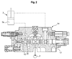
FIG. 2 is a sectional view explaining prevention of a fine drive of a boom cylinder during traveling of heavy equipment according to an embodiment of the present invention; and -
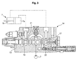
FIG. 3 is a sectional view explaining prevention of a fine drive of a boom cylinder during traveling of heavy equipment according to another embodiment of the present invention. - Hereinafter, preferred embodiments of the present invention will be described with reference to the accompanying drawings. The matters defined in the description, such as the detailed construction and elements, are nothing but specific details provided to assist those of ordinary skill in the art in a comprehensive understanding of the invention, and thus the present invention is not limited thereto.
- As illustrated in
FIG. 2 , a hydraulic circuit to prevent a bucket separation from a bucket rest during traveling of heavy equipment, according to an embodiment of the present invention, includes first and secondhydraulic pumps 1 and 2, aboom cylinder 3 driven by shifting of aspool 12 for the boom cylinder installed in a flow path of the first hydraulic pump 1, anarm cylinder 7 driven by shifting of aspool 13 for the arm cylinder installed in a flow path of the secondhydraulic pump 2, and a boomconfluence logic valve 10 for making hydraulic fluid fed from the secondhydraulic pump 2 join hydraulic fluid of theboom cylinder 3. - The hydraulic circuit according to an embodiment of the present invention also includes a first port C formed to connect with a
large chamber 3a of theboom cylinder 3 in ahousing 14 in which thespool 12 for the boom cylinder is shiftably installed, a second port R formed to connect with a hydraulic tank T in thehousing 14, and afirst orifice 15 formed between thehousing 14 and a land part of thespool 12 for the boom cylinder located between the first port C and the second port R. - During long traveling of the heavy equipment, a very small amount of hydraulic fluid, which is fed from the second
hydraulic pump 2 to thelarge chamber 3a of theboom cylinder 3 through the orifice of the boomconfluence logic valve 10 and the first port C, drains to the hydraulic tank T through thefirst orifice 15 and the second port R to prevent a change of stroke of theboom cylinder 3. - In this case, the construction including the second
hydraulic pump 2, theboom cylinder 3, and thespool 12 for the boom cylinder is substantially equal to the construction as illustrated inFIG. 1 , and thus the detailed description thereof will be omitted. In the description of the present invention, the same drawing reference numerals are used for the same elements across various figures. - Hereinafter, the operation of the hydraulic circuit to prevent a bucket separation from a bucket rest during traveling of heavy equipment, according to an embodiment of the present invention, will be described with reference to the accompanying drawings.
- As illustrated in
FIG. 2 , a part of high-pressure hydraulic fluid fed from the secondhydraulic pump 2 is supplied to a high-pressure flow path P of thehousing 14 in which thespool 12 for the boom cylinder is installed to be kept in a neutral state. The hydraulic fluid supplied to the high-pressure flow path P leaks to the first port C through asecond orifice 20 formed between the high-pressure flow path P and the first port C. - The hydraulic fluid leaking to the first port C flows to the second port R through the
first orifice 15 formed between the first port C and the second port R, and then drains to the hydraulic tank T. - In this case, the
first orifice 15 is formed to have a size larger than that of the second orifice 20 (i.e., a gap formed between thehousing 14 and the land part of thespool 12 for the boom cylinder located between the high-pressure path P and the first port C) formed between the high-pressure path P and the first port C. - Accordingly, if a very small amount of hydraulic fluid fed to the high-pressure flow path P during traveling leaks to the first port C connected with the
large chamber 3a of theboom cylinder 3 through thesecond orifice 20, the hydraulic fluid leaking to the first port C drains to the hydraulic tank T through thefirst orifice 15. At this time, since the size of thefirst orifice 15 is larger than that of thesecond orifice 20, the hydraulic fluid leaking to the first port C is rapidly discharged to the hydraulic tank T. - Accordingly, the supply of a very small amount of hydraulic fluid, which is fed to the high-pressure flow path P, to the
large chamber 3a of theboom cylinder 3 is intercepted, and thus the change of stroke of theboom cylinder 3 is prevented. - During long traveling of the heavy equipment, all spools except for the spool 11 for the traveling motor are kept in a neutral state, and a very small amount of hydraulic fluid, which is fed from the second
hydraulic pump 2 to theboom cylinder 3, drains to the hydraulic tank T, so that the fine drive of theboom cylinder 3 is prevented. - Accordingly, even in the case where the wheel type heavy equipment travels for a long time, the fine drive of the
boom cylinder 3 is prevented, and thus the bucket is prevented from seceding from the bucket rest. - As illustrated in
FIG. 3 , a hydraulic circuit to prevent a bucket separation from a bucket rest during traveling of heavy equipment, according to another embodiment of the present invention, includes first and secondhydraulic pumps 1 and 2, aboom cylinder 3 driven by shifting of aspool 12 for the boom cylinder installed in a flow path of the first hydraulic pump 1, anarm cylinder 7 driven by shifting of aspool 13 for the arm cylinder installed in a flow path of the secondhydraulic pump 2, and a boomconfluence logic valve 10 for making hydraulic fluid fed from the secondhydraulic pump 2 join hydraulic fluid of theboom cylinder 3. - The hydraulic circuit according to another embodiment of the present invention also includes a first port C1 formed to connect with a
large chamber 7a of thearm cylinder 7 in ahousing 14 in which thespool 13 for the arm cylinder is shiftably installed, a second port R1 formed to connect with a hydraulic tank T in thehousing 14, a third orifice 16 (i.e., a gap formed between thehousing 14 and a land part of thespool 13 for the arm cylinder) formed between thehousing 14 and a land part of thespool 13 for the arm cylinder located between the first port C1 and the second port R1, a third port C2 formed to connect with the asmall chamber 7b of thearm cylinder 7 in thehousing 14, a fourth port R2 formed to connect with the hydraulic tank T in thehousing 14, and a fourth orifice 17 (i.e., a gap formed between thehousing 14 and the land part of thespool 13 for the arm cylinder) formed between thehousing 14 and the land part of thespool 13 for the arm cylinder located between the third port C2 and the fourth port R2. - During long traveling of the heavy equipment, a very small amount of hydraulic fluid, which is fed from the second
hydraulic pump 2 to thelarge chamber 7a of thearm cylinder 7 through the first port C1 due to the spool leakage, drains to the hydraulic tank T through thethird orifice 16 and the second port R1, or a very small amount of hydraulic fluid, which is fed from the secondhydraulic pump 2 to thesmall chamber 7b of thearm cylinder 7 through the third port C2 due to the spool leakage, drains to the hydraulic tank T through thefourth orifice 17 and the fourth port R2 to prevent a change of stroke of thearm cylinder 7. - In this case, the construction including the second
hydraulic pump 2, thearm cylinder 7, and thespool 13 for the arm cylinder is substantially equal to the construction as illustrated inFIG. 1 , and thus the detailed description thereof will be omitted. In the description of the present invention, the same drawing reference numerals are used for the same elements across various figures. - Hereinafter, the operation of the hydraulic circuit to prevent a bucket separation from a bucket rest during traveling of heavy equipment, according to another embodiment of the present invention, will be described with reference to the accompanying drawings.
- As illustrated in
FIG. 3 , a part of high-pressure hydraulic fluid fed from the secondhydraulic pump 2 is supplied to a high-pressure flow path P of thehousing 14 in which thespool 13 for the arm cylinder is installed to be kept in a neutral state. The hydraulic fluid supplied to the high-pressure flow path P leaks to the first port C1 through afifth orifice 21 formed between the high-pressure flow path P and the first port C1. - The hydraulic fluid leaking to the first port C1 flows to the second port R1 through the
third orifice 16 formed between the first port C1 and the second port R1, and then drains to the hydraulic tank T. - In this case, the
third orifice 16 is formed to have a size larger than that of the fifth orifice 21 (i.e., a gap formed between thehousing 14 and the land part of thespool 13 for the arm cylinder located between the high-pressure path P and the first port C1) formed between the high-pressure path P and the first port C1. - Accordingly, if a very small amount of hydraulic fluid, which is fed from the second
hydraulic pump 2 to the high-pressure flow path P due to the spool leakage, leaks to the first port C1 connected with thelarge chamber 7a of thearm cylinder 7 through thefifth orifice 21, the hydraulic fluid leaking to the first port C1 drains to the hydraulic tank T through thethird orifice 16. - Accordingly, the supply of a part of hydraulic fluid, which is fed to the high-pressure flow path P during traveling, to the
large chamber 7a of thearm cylinder 7 is intercepted, and thus the stroke-out of thearm cylinder 7 is prevented. - On the other hand, a part of high-pressure hydraulic fluid fed from the second
hydraulic pump 2 to the high-pressure flow path P leaks to the third port C2 through a sixth orifice 22 (i.e., a gap formed between thehousing 14 and the land part of thespool 13 for the arm cylinder located between the high-pressure path P and the third port C2) formed between the high-pressure flow path P and the second port C2. - The hydraulic fluid leaking to the third port C2 drains to the hydraulic tank T through the
fourth orifice 17 formed between the third port C2 and the fourth port R2. In this case, thefourth orifice 17 is formed to have a size larger than that of thesixth orifice 22 formed between the high-pressure path P and the third port C2. - Accordingly, if a very small amount of hydraulic fluid, which is fed from the second
hydraulic pump 2 to the high-pressure flow path P due to the spool leakage, leaks to the third port C2 connected with thesmall chamber 7b of thearm cylinder 7 through thesixth orifice 22, the hydraulic fluid leaking to the third port C2 drains to the hydraulic tank T through thefourth orifice 17. - Accordingly, the supply of a part of the hydraulic fluid, which is fed to the high-pressure flow path P during traveling, to the
small chamber 7b of thearm cylinder 7 is intercepted, and thus the stroke-in of thearm cylinder 7 is prevented. - As described above, during long traveling of the heavy equipment, all spools except for the spool 11 for the traveling motor are kept in a neutral state, and a very small amount of hydraulic fluid, which is fed from the second
hydraulic pump 2 to thearm cylinder 7, drains to the hydraulic tank T, so that the change of stroke of thearm cylinder 7 is prevented. - Accordingly, even in the case where the wheel type heavy equipment travels for a long time, the bucket is prevented from seceding from the bucket rest due to the change of stroke (i.e., stroke-out or stroke-in) of the
arm cylinder 7. - From the foregoing, it will be apparent that the hydraulic circuit to prevent a bucket separation from a bucket rest during traveling of heavy equipment, according to embodiments of the present invention, has the following advantages.
- During long traveling of wheel type heavy equipment, the bucket is prevented from being separated from the bucket rest by draining a very small amount of high-pressure hydraulic fluid, which is fed to the boom cylinder or the arm cylinder, to the hydraulic tank side, and thus it is not required for an operator to adjust the position of boom and arm during the traveling of the heavy equipment to secure safe & comfort driving.
- Although preferred embodiment of the present invention has been described for illustrative purposes, those skilled in the art will appreciate that various modifications, additions and substitutions are possible, without departing from the scope and spirit of the invention as disclosed in the accompanying claims.
Claims (4)
- A hydraulic circuit to prevent a bucket separation from a bucket rest during traveling of heavy equipment, including first and second hydraulic pumps, a boom cylinder driven by shifting of a spool for the boom cylinder installed in a flow path of the first hydraulic pump, an arm cylinder driven by shifting of a spool for the arm cylinder installed in a flow path of the second hydraulic pump, and a boom confluence logic valve for making hydraulic fluid fed from the second hydraulic pump join hydraulic fluid of the boom cylinder, the hydraulic circuit comprising:a first port formed to connect with a large chamber of the boom cylinder in a housing in which the spool for the boom cylinder is shiftably installed;a second port formed to connect with a hydraulic tank in the housing; anda first orifice formed between the housing and a land part of the spool for the boom cylinder located between the first port and the second port;wherein during long traveling of the heavy equipment, a very small amount of hydraulic fluid fed from the second hydraulic pump to the large chamber of the boom cylinder drains to the hydraulic tank through the first orifice to prevent a change of stroke of the boom cylinder.
- A hydraulic circuit to prevent a bucket separation from a bucket rest during traveling of heavy equipment, including first and second hydraulic pumps, a boom cylinder driven by shifting of a spool for the boom cylinder installed in a flow path of the first hydraulic pump, an arm cylinder driven by shifting of a spool for the arm cylinder installed in a flow path of the second hydraulic pump, and a boom confluence logic valve for making hydraulic fluid fed from the second hydraulic pump join hydraulic fluid of the boom cylinder, the hydraulic circuit comprising:a first port formed to connect with a large chamber of the arm cylinder in a housing in which the spool for the arm cylinder is shiftably installed;a second port formed to connect with a hydraulic tank in the housing;a third orifice formed between the housing and a land part of the spool for the arm cylinder located between the first port and the second port;a third port formed to connect with the a small chamber of the arm cylinder in the housing;a fourth port formed to connect with the hydraulic tank in the housing; anda fourth orifice formed between the housing and the land part of the spool for the arm cylinder located between the third port and the fourth port;wherein during long traveling of the heavy equipment, a very small amount of hydraulic fluid fed from the second hydraulic pump to the large chamber of the arm cylinder drains to the hydraulic tank through the third orifice, and a very small amount of hydraulic fluid fed from the second hydraulic pump to the small chamber of the arm cylinder drains to the hydraulic tank through the fourth orifice to prevent a change of stroke of the arm cylinder.
- The hydraulic circuit of claim 1, wherein the first orifice has a size larger than that of a second orifice formed between the housing and the land part of the spool for the boom cylinder located between a high-pressure flow path formed in the housing and the first port.
- The hydraulic circuit of claim 2, the third orifice has a size larger than that of a fifth orifice formed between the housing and the land part of the spool for the arm cylinder located between a high-pressure flow path formed in the housing and the first port, and the fourth orifice has a size larger than that of a sixth orifice formed between the housing and the land part of the spool for the arm cylinder located between a high-pressure flow path formed in the housing and the third port.
Applications Claiming Priority (1)
| Application Number | Priority Date | Filing Date | Title |
|---|---|---|---|
| KR1020070026495A KR100890984B1 (en) | 2007-03-19 | 2007-03-19 | Hydraulic circuit to prevent the bucket rest from the bucket while driving |
Publications (2)
| Publication Number | Publication Date |
|---|---|
| EP1972726A1 true EP1972726A1 (en) | 2008-09-24 |
| EP1972726B1 EP1972726B1 (en) | 2011-05-25 |
Family
ID=39400373
Family Applications (1)
| Application Number | Title | Priority Date | Filing Date |
|---|---|---|---|
| EP08004666A Ceased EP1972726B1 (en) | 2007-03-19 | 2008-03-13 | Hydraulic circuit to prevent bucket separation from bucket rest during traveling of heavy equipment |
Country Status (5)
| Country | Link |
|---|---|
| US (1) | US8104276B2 (en) |
| EP (1) | EP1972726B1 (en) |
| JP (1) | JP2008231908A (en) |
| KR (1) | KR100890984B1 (en) |
| CN (1) | CN101270766B (en) |
Cited By (2)
| Publication number | Priority date | Publication date | Assignee | Title |
|---|---|---|---|---|
| EP2781661A3 (en) * | 2013-03-22 | 2015-01-28 | Hitachi Construction Machinery Co., Ltd. | Traveling control device for wheeled work vehicle |
| EP2876306A4 (en) * | 2012-07-19 | 2016-05-25 | Volvo Constr Equip Ab | FLOW LIMIT VALVE FOR CONSTRUCTION MACHINERY |
Families Citing this family (8)
| Publication number | Priority date | Publication date | Assignee | Title |
|---|---|---|---|---|
| JP2012225391A (en) * | 2011-04-18 | 2012-11-15 | Hitachi Constr Mach Co Ltd | Hydraulic driving device for working machine |
| EP3026181B1 (en) * | 2013-07-24 | 2018-11-14 | Volvo Construction Equipment AB | Hydraulic circuit for construction machine |
| KR20160077508A (en) | 2014-12-23 | 2016-07-04 | 현대중공업 주식회사 | Variable type bucket rest for wheel excavator |
| JP6569852B2 (en) * | 2015-06-25 | 2019-09-04 | ヤンマー株式会社 | Hydraulic device |
| CN105805071B (en) * | 2016-05-09 | 2017-12-05 | 青岛雷沃工程机械有限公司 | A kind of one-way valve mechanism and rotation oil system for excavator swing arm |
| CN106640810A (en) * | 2016-11-21 | 2017-05-10 | 湖南鸿辉科技有限公司 | Integral type multi-way valve and working method thereof |
| JP7431006B2 (en) * | 2019-09-27 | 2024-02-14 | ナブテスコ株式会社 | hydraulic control circuit |
| KR102403192B1 (en) | 2021-09-30 | 2022-05-30 | (주)케이티씨이디엠 | ultra-fine small hole electrical discharging machine |
Citations (3)
| Publication number | Priority date | Publication date | Assignee | Title |
|---|---|---|---|---|
| JPH04258417A (en) * | 1991-02-13 | 1992-09-14 | Hitachi Constr Mach Co Ltd | Flow control valve and boom rise prevention device using the flow control valve |
| US5485724A (en) * | 1992-05-22 | 1996-01-23 | Hitachi Construction Machinery Co., Ltd. | Hydraulic drive system |
| JP2000129728A (en) * | 1998-10-23 | 2000-05-09 | Hitachi Constr Mach Co Ltd | Hydraulic traveling working vehicle |
Family Cites Families (6)
| Publication number | Priority date | Publication date | Assignee | Title |
|---|---|---|---|---|
| JPH0649633Y2 (en) * | 1988-06-07 | 1994-12-14 | 油谷重工株式会社 | Hydraulic circuit of hydraulic excavator |
| US5481872A (en) * | 1991-11-25 | 1996-01-09 | Kabushiki Kaisha Komatsu Seisakusho | Hydraulic circuit for operating plural actuators and its pressure compensating valve and maximum load pressure detector |
| JP2002081409A (en) * | 2000-09-08 | 2002-03-22 | Hitachi Constr Mach Co Ltd | Hydraulic circuit for traveling vehicle |
| KR100652868B1 (en) * | 2002-04-24 | 2006-12-01 | 볼보 컨스트럭션 이키프먼트 홀딩 스웨덴 에이비 | Excavator tool movement prevention hydraulic circuit. |
| KR100532165B1 (en) * | 2003-04-04 | 2005-11-30 | 볼보 컨스트럭션 이키프먼트 홀딩 스웨덴 에이비 | hydraulic circuit of protect boom lift for track |
| JP4258417B2 (en) | 2004-04-16 | 2009-04-30 | パナソニック株式会社 | Electric jar rice cooker |
-
2007
- 2007-03-19 KR KR1020070026495A patent/KR100890984B1/en not_active Expired - Fee Related
-
2008
- 2008-03-12 US US12/075,590 patent/US8104276B2/en active Active
- 2008-03-12 JP JP2008061985A patent/JP2008231908A/en active Pending
- 2008-03-13 EP EP08004666A patent/EP1972726B1/en not_active Ceased
- 2008-03-19 CN CN200810082793.0A patent/CN101270766B/en not_active Expired - Fee Related
Patent Citations (3)
| Publication number | Priority date | Publication date | Assignee | Title |
|---|---|---|---|---|
| JPH04258417A (en) * | 1991-02-13 | 1992-09-14 | Hitachi Constr Mach Co Ltd | Flow control valve and boom rise prevention device using the flow control valve |
| US5485724A (en) * | 1992-05-22 | 1996-01-23 | Hitachi Construction Machinery Co., Ltd. | Hydraulic drive system |
| JP2000129728A (en) * | 1998-10-23 | 2000-05-09 | Hitachi Constr Mach Co Ltd | Hydraulic traveling working vehicle |
Cited By (2)
| Publication number | Priority date | Publication date | Assignee | Title |
|---|---|---|---|---|
| EP2876306A4 (en) * | 2012-07-19 | 2016-05-25 | Volvo Constr Equip Ab | FLOW LIMIT VALVE FOR CONSTRUCTION MACHINERY |
| EP2781661A3 (en) * | 2013-03-22 | 2015-01-28 | Hitachi Construction Machinery Co., Ltd. | Traveling control device for wheeled work vehicle |
Also Published As
| Publication number | Publication date |
|---|---|
| JP2008231908A (en) | 2008-10-02 |
| US20080229738A1 (en) | 2008-09-25 |
| EP1972726B1 (en) | 2011-05-25 |
| CN101270766A (en) | 2008-09-24 |
| KR20080085273A (en) | 2008-09-24 |
| CN101270766B (en) | 2014-03-19 |
| KR100890984B1 (en) | 2009-03-27 |
| US8104276B2 (en) | 2012-01-31 |
Similar Documents
| Publication | Publication Date | Title |
|---|---|---|
| US8104276B2 (en) | Hydraulic circuit to prevent bucket separation from bucket rest during traveling of heavy equipment | |
| US20180127949A1 (en) | Hydraulic circuit and working machine | |
| US7921764B2 (en) | Hydraulic control device of working machine | |
| US20080289325A1 (en) | Traveling device for crawler type heavy equipment | |
| EP1975324B1 (en) | Hydraulic circuit for construction equipment | |
| JP4193830B2 (en) | Hydraulic control device for work machine | |
| JP2010048417A (en) | Hydraulic system for construction machine | |
| KR20130085989A (en) | Construction machinery and hydraulic circuit thereof | |
| JP6514522B2 (en) | Hydraulic drive system of unloading valve and hydraulic shovel | |
| EP2602491B1 (en) | Construction machine having hydraulic circuit | |
| KR20090028216A (en) | Hydraulic circuit for heavy construction equipment | |
| EP1726723B1 (en) | Working machine | |
| CN104895138B (en) | Oil pressure driving system of building machinery | |
| CN112424485A (en) | Hydraulic circuit for construction machine | |
| KR20110072587A (en) | Hydraulic System for Construction Equipment | |
| US20140345268A1 (en) | Travel control system for construction machinery | |
| KR101669680B1 (en) | Hydraulic circuit for construction machinery | |
| US20160130787A1 (en) | Flow rate control valve for construction machine | |
| KR20190115050A (en) | Directional valve | |
| JP2007120512A (en) | Hydraulic control device for working machine | |
| KR100974285B1 (en) | Normal open hydraulic circuit | |
| EP3821136B1 (en) | Hydraulic machine comprising a hydraulic circuit | |
| JP2005265049A (en) | Hydraulic drive unit for working machine | |
| JP2003232305A (en) | Fluid pressure circuit | |
| KR102510441B1 (en) | Hydraulic system of construction equipment |
Legal Events
| Date | Code | Title | Description |
|---|---|---|---|
| PUAI | Public reference made under article 153(3) epc to a published international application that has entered the european phase |
Free format text: ORIGINAL CODE: 0009012 |
|
| AK | Designated contracting states |
Kind code of ref document: A1 Designated state(s): AT BE BG CH CY CZ DE DK EE ES FI FR GB GR HR HU IE IS IT LI LT LU LV MC MT NL NO PL PT RO SE SI SK TR |
|
| AX | Request for extension of the european patent |
Extension state: AL BA MK RS |
|
| RIN1 | Information on inventor provided before grant (corrected) |
Inventor name: LEE, BYUNG HO |
|
| 17P | Request for examination filed |
Effective date: 20090304 |
|
| 17Q | First examination report despatched |
Effective date: 20090403 |
|
| AKX | Designation fees paid |
Designated state(s): DE FR GB IT |
|
| GRAP | Despatch of communication of intention to grant a patent |
Free format text: ORIGINAL CODE: EPIDOSNIGR1 |
|
| GRAS | Grant fee paid |
Free format text: ORIGINAL CODE: EPIDOSNIGR3 |
|
| GRAA | (expected) grant |
Free format text: ORIGINAL CODE: 0009210 |
|
| AK | Designated contracting states |
Kind code of ref document: B1 Designated state(s): DE FR GB IT |
|
| REG | Reference to a national code |
Ref country code: GB Ref legal event code: FG4D |
|
| REG | Reference to a national code |
Ref country code: DE Ref legal event code: R096 Ref document number: 602008007131 Country of ref document: DE Effective date: 20110707 |
|
| PLBE | No opposition filed within time limit |
Free format text: ORIGINAL CODE: 0009261 |
|
| STAA | Information on the status of an ep patent application or granted ep patent |
Free format text: STATUS: NO OPPOSITION FILED WITHIN TIME LIMIT |
|
| 26N | No opposition filed |
Effective date: 20120228 |
|
| REG | Reference to a national code |
Ref country code: DE Ref legal event code: R097 Ref document number: 602008007131 Country of ref document: DE Effective date: 20120228 |
|
| REG | Reference to a national code |
Ref country code: FR Ref legal event code: PLFP Year of fee payment: 9 |
|
| REG | Reference to a national code |
Ref country code: FR Ref legal event code: PLFP Year of fee payment: 10 |
|
| REG | Reference to a national code |
Ref country code: FR Ref legal event code: PLFP Year of fee payment: 11 |
|
| PGFP | Annual fee paid to national office [announced via postgrant information from national office to epo] |
Ref country code: FR Payment date: 20230323 Year of fee payment: 16 |
|
| PGFP | Annual fee paid to national office [announced via postgrant information from national office to epo] |
Ref country code: IT Payment date: 20230321 Year of fee payment: 16 Ref country code: GB Payment date: 20230321 Year of fee payment: 16 Ref country code: DE Payment date: 20230328 Year of fee payment: 16 |
|
| REG | Reference to a national code |
Ref country code: DE Ref legal event code: R119 Ref document number: 602008007131 Country of ref document: DE |
|
| GBPC | Gb: european patent ceased through non-payment of renewal fee |
Effective date: 20240313 |
|
| PG25 | Lapsed in a contracting state [announced via postgrant information from national office to epo] |
Ref country code: DE Free format text: LAPSE BECAUSE OF NON-PAYMENT OF DUE FEES Effective date: 20241001 |
|
| PG25 | Lapsed in a contracting state [announced via postgrant information from national office to epo] |
Ref country code: GB Free format text: LAPSE BECAUSE OF NON-PAYMENT OF DUE FEES Effective date: 20240313 |
|
| PG25 | Lapsed in a contracting state [announced via postgrant information from national office to epo] |
Ref country code: FR Free format text: LAPSE BECAUSE OF NON-PAYMENT OF DUE FEES Effective date: 20240331 |
|
| PG25 | Lapsed in a contracting state [announced via postgrant information from national office to epo] |
Ref country code: GB Free format text: LAPSE BECAUSE OF NON-PAYMENT OF DUE FEES Effective date: 20240313 Ref country code: FR Free format text: LAPSE BECAUSE OF NON-PAYMENT OF DUE FEES Effective date: 20240331 Ref country code: DE Free format text: LAPSE BECAUSE OF NON-PAYMENT OF DUE FEES Effective date: 20241001 |
|
| PG25 | Lapsed in a contracting state [announced via postgrant information from national office to epo] |
Ref country code: IT Free format text: LAPSE BECAUSE OF NON-PAYMENT OF DUE FEES Effective date: 20240313 |