CN112424485A - Hydraulic circuit for construction machine - Google Patents
Hydraulic circuit for construction machine Download PDFInfo
- Publication number
- CN112424485A CN112424485A CN201980048928.8A CN201980048928A CN112424485A CN 112424485 A CN112424485 A CN 112424485A CN 201980048928 A CN201980048928 A CN 201980048928A CN 112424485 A CN112424485 A CN 112424485A
- Authority
- CN
- China
- Prior art keywords
- pump
- actuator
- port
- valve
- pressure
- Prior art date
- Legal status (The legal status is an assumption and is not a legal conclusion. Google has not performed a legal analysis and makes no representation as to the accuracy of the status listed.)
- Pending
Links
Images

Classifications
-
- F—MECHANICAL ENGINEERING; LIGHTING; HEATING; WEAPONS; BLASTING
- F15—FLUID-PRESSURE ACTUATORS; HYDRAULICS OR PNEUMATICS IN GENERAL
- F15B—SYSTEMS ACTING BY MEANS OF FLUIDS IN GENERAL; FLUID-PRESSURE ACTUATORS, e.g. SERVOMOTORS; DETAILS OF FLUID-PRESSURE SYSTEMS, NOT OTHERWISE PROVIDED FOR
- F15B11/00—Servomotor systems without provision for follow-up action; Circuits therefor
- F15B11/16—Servomotor systems without provision for follow-up action; Circuits therefor with two or more servomotors
- F15B11/161—Servomotor systems without provision for follow-up action; Circuits therefor with two or more servomotors with sensing of servomotor demand or load
- F15B11/162—Servomotor systems without provision for follow-up action; Circuits therefor with two or more servomotors with sensing of servomotor demand or load for giving priority to particular servomotors or users
-
- E—FIXED CONSTRUCTIONS
- E02—HYDRAULIC ENGINEERING; FOUNDATIONS; SOIL SHIFTING
- E02F—DREDGING; SOIL-SHIFTING
- E02F9/00—Component parts of dredgers or soil-shifting machines, not restricted to one of the kinds covered by groups E02F3/00 - E02F7/00
- E02F9/20—Drives; Control devices
- E02F9/22—Hydraulic or pneumatic drives
- E02F9/2278—Hydraulic circuits
-
- E—FIXED CONSTRUCTIONS
- E02—HYDRAULIC ENGINEERING; FOUNDATIONS; SOIL SHIFTING
- E02F—DREDGING; SOIL-SHIFTING
- E02F9/00—Component parts of dredgers or soil-shifting machines, not restricted to one of the kinds covered by groups E02F3/00 - E02F7/00
- E02F9/20—Drives; Control devices
- E02F9/22—Hydraulic or pneumatic drives
- E02F9/2221—Control of flow rate; Load sensing arrangements
- E02F9/2225—Control of flow rate; Load sensing arrangements using pressure-compensating valves
- E02F9/2228—Control of flow rate; Load sensing arrangements using pressure-compensating valves including an electronic controller
-
- E—FIXED CONSTRUCTIONS
- E02—HYDRAULIC ENGINEERING; FOUNDATIONS; SOIL SHIFTING
- E02F—DREDGING; SOIL-SHIFTING
- E02F9/00—Component parts of dredgers or soil-shifting machines, not restricted to one of the kinds covered by groups E02F3/00 - E02F7/00
- E02F9/20—Drives; Control devices
- E02F9/22—Hydraulic or pneumatic drives
- E02F9/225—Control of steering, e.g. for hydraulic motors driving the vehicle tracks
-
- E—FIXED CONSTRUCTIONS
- E02—HYDRAULIC ENGINEERING; FOUNDATIONS; SOIL SHIFTING
- E02F—DREDGING; SOIL-SHIFTING
- E02F9/00—Component parts of dredgers or soil-shifting machines, not restricted to one of the kinds covered by groups E02F3/00 - E02F7/00
- E02F9/20—Drives; Control devices
- E02F9/22—Hydraulic or pneumatic drives
- E02F9/2264—Arrangements or adaptations of elements for hydraulic drives
- E02F9/2267—Valves or distributors
-
- E—FIXED CONSTRUCTIONS
- E02—HYDRAULIC ENGINEERING; FOUNDATIONS; SOIL SHIFTING
- E02F—DREDGING; SOIL-SHIFTING
- E02F9/00—Component parts of dredgers or soil-shifting machines, not restricted to one of the kinds covered by groups E02F3/00 - E02F7/00
- E02F9/20—Drives; Control devices
- E02F9/22—Hydraulic or pneumatic drives
- E02F9/2221—Control of flow rate; Load sensing arrangements
- E02F9/2225—Control of flow rate; Load sensing arrangements using pressure-compensating valves
-
- F—MECHANICAL ENGINEERING; LIGHTING; HEATING; WEAPONS; BLASTING
- F15—FLUID-PRESSURE ACTUATORS; HYDRAULICS OR PNEUMATICS IN GENERAL
- F15B—SYSTEMS ACTING BY MEANS OF FLUIDS IN GENERAL; FLUID-PRESSURE ACTUATORS, e.g. SERVOMOTORS; DETAILS OF FLUID-PRESSURE SYSTEMS, NOT OTHERWISE PROVIDED FOR
- F15B11/00—Servomotor systems without provision for follow-up action; Circuits therefor
- F15B11/16—Servomotor systems without provision for follow-up action; Circuits therefor with two or more servomotors
-
- F—MECHANICAL ENGINEERING; LIGHTING; HEATING; WEAPONS; BLASTING
- F15—FLUID-PRESSURE ACTUATORS; HYDRAULICS OR PNEUMATICS IN GENERAL
- F15B—SYSTEMS ACTING BY MEANS OF FLUIDS IN GENERAL; FLUID-PRESSURE ACTUATORS, e.g. SERVOMOTORS; DETAILS OF FLUID-PRESSURE SYSTEMS, NOT OTHERWISE PROVIDED FOR
- F15B2211/00—Circuits for servomotor systems
- F15B2211/30—Directional control
- F15B2211/305—Directional control characterised by the type of valves
- F15B2211/30525—Directional control valves, e.g. 4/3-directional control valve
- F15B2211/3053—In combination with a pressure compensating valve
- F15B2211/30535—In combination with a pressure compensating valve the pressure compensating valve is arranged between pressure source and directional control valve
-
- F—MECHANICAL ENGINEERING; LIGHTING; HEATING; WEAPONS; BLASTING
- F15—FLUID-PRESSURE ACTUATORS; HYDRAULICS OR PNEUMATICS IN GENERAL
- F15B—SYSTEMS ACTING BY MEANS OF FLUIDS IN GENERAL; FLUID-PRESSURE ACTUATORS, e.g. SERVOMOTORS; DETAILS OF FLUID-PRESSURE SYSTEMS, NOT OTHERWISE PROVIDED FOR
- F15B2211/00—Circuits for servomotor systems
- F15B2211/30—Directional control
- F15B2211/305—Directional control characterised by the type of valves
- F15B2211/30525—Directional control valves, e.g. 4/3-directional control valve
- F15B2211/3053—In combination with a pressure compensating valve
- F15B2211/30555—Inlet and outlet of the pressure compensating valve being connected to the directional control valve
-
- F—MECHANICAL ENGINEERING; LIGHTING; HEATING; WEAPONS; BLASTING
- F15—FLUID-PRESSURE ACTUATORS; HYDRAULICS OR PNEUMATICS IN GENERAL
- F15B—SYSTEMS ACTING BY MEANS OF FLUIDS IN GENERAL; FLUID-PRESSURE ACTUATORS, e.g. SERVOMOTORS; DETAILS OF FLUID-PRESSURE SYSTEMS, NOT OTHERWISE PROVIDED FOR
- F15B2211/00—Circuits for servomotor systems
- F15B2211/60—Circuit components or control therefor
- F15B2211/63—Electronic controllers
- F15B2211/6303—Electronic controllers using input signals
- F15B2211/6306—Electronic controllers using input signals representing a pressure
- F15B2211/6313—Electronic controllers using input signals representing a pressure the pressure being a load pressure
-
- F—MECHANICAL ENGINEERING; LIGHTING; HEATING; WEAPONS; BLASTING
- F15—FLUID-PRESSURE ACTUATORS; HYDRAULICS OR PNEUMATICS IN GENERAL
- F15B—SYSTEMS ACTING BY MEANS OF FLUIDS IN GENERAL; FLUID-PRESSURE ACTUATORS, e.g. SERVOMOTORS; DETAILS OF FLUID-PRESSURE SYSTEMS, NOT OTHERWISE PROVIDED FOR
- F15B2211/00—Circuits for servomotor systems
- F15B2211/70—Output members, e.g. hydraulic motors or cylinders or control therefor
- F15B2211/705—Output members, e.g. hydraulic motors or cylinders or control therefor characterised by the type of output members or actuators
- F15B2211/7051—Linear output members
- F15B2211/7053—Double-acting output members
-
- F—MECHANICAL ENGINEERING; LIGHTING; HEATING; WEAPONS; BLASTING
- F15—FLUID-PRESSURE ACTUATORS; HYDRAULICS OR PNEUMATICS IN GENERAL
- F15B—SYSTEMS ACTING BY MEANS OF FLUIDS IN GENERAL; FLUID-PRESSURE ACTUATORS, e.g. SERVOMOTORS; DETAILS OF FLUID-PRESSURE SYSTEMS, NOT OTHERWISE PROVIDED FOR
- F15B2211/00—Circuits for servomotor systems
- F15B2211/70—Output members, e.g. hydraulic motors or cylinders or control therefor
- F15B2211/705—Output members, e.g. hydraulic motors or cylinders or control therefor characterised by the type of output members or actuators
- F15B2211/7058—Rotary output members
-
- F—MECHANICAL ENGINEERING; LIGHTING; HEATING; WEAPONS; BLASTING
- F15—FLUID-PRESSURE ACTUATORS; HYDRAULICS OR PNEUMATICS IN GENERAL
- F15B—SYSTEMS ACTING BY MEANS OF FLUIDS IN GENERAL; FLUID-PRESSURE ACTUATORS, e.g. SERVOMOTORS; DETAILS OF FLUID-PRESSURE SYSTEMS, NOT OTHERWISE PROVIDED FOR
- F15B2211/00—Circuits for servomotor systems
- F15B2211/70—Output members, e.g. hydraulic motors or cylinders or control therefor
- F15B2211/71—Multiple output members, e.g. multiple hydraulic motors or cylinders
- F15B2211/7135—Combinations of output members of different types, e.g. single-acting cylinders with rotary motors
-
- F—MECHANICAL ENGINEERING; LIGHTING; HEATING; WEAPONS; BLASTING
- F15—FLUID-PRESSURE ACTUATORS; HYDRAULICS OR PNEUMATICS IN GENERAL
- F15B—SYSTEMS ACTING BY MEANS OF FLUIDS IN GENERAL; FLUID-PRESSURE ACTUATORS, e.g. SERVOMOTORS; DETAILS OF FLUID-PRESSURE SYSTEMS, NOT OTHERWISE PROVIDED FOR
- F15B2211/00—Circuits for servomotor systems
- F15B2211/70—Output members, e.g. hydraulic motors or cylinders or control therefor
- F15B2211/78—Control of multiple output members
- F15B2211/781—Control of multiple output members one or more output members having priority
Abstract
A hydraulic circuit of a construction machine is provided with: a first pump line connecting a discharge port of the pump and a pump port of the first direction switching valve; a second pump line branched from the first pump line and connected to a pump port of the second directional control valve; and a priority valve disposed on the second pump line. The priority valve is configured as follows: when the differential pressure between the discharge pressure of the pump and the load pressure of the first actuator is greater than a set value, the second pump line is fully opened, and when the differential pressure is less than the set value, the opening degree of the second pump line is decreased as the differential pressure is decreased.
Description
Technical Field
The present invention relates to a hydraulic circuit mounted on a construction machine.
Background
In general, a hydraulic actuator is used for both a traveling actuator and a working device actuator in a construction machine. In the case of a small-sized construction machine, a hydraulic circuit having pressure oil sources of both actuators as one pump, that is, a so-called "single pump system" may be mounted. In the case where the travel operation and the operation of the working device are performed simultaneously in the single-pump system, the pump discharge flow rate may be insufficient with respect to the required flow rate, and both the travel speed and the operation speed of the working device may be insufficient.
In this regard, patent document 1 shows an example of an arm as a working device and an example of an arm cylinder as a hydraulic actuator for operating the arm cylinder. The single pump system includes: a direction switching valve for traveling that operates in accordance with a traveling operation; a directional control valve for the arm, which operates in response to the operation of the arm; a traveling pressure compensation valve for controlling a differential pressure between upstream and downstream sides of the traveling direction switching valve; and an arm pressure compensation valve for controlling a pressure difference between upstream and downstream sides of the arm directional control valve.
The system is also provided with a control pressure output means for outputting a control pressure to the travel pressure compensation valve and the arm pressure compensation valve based on the travel load pressure and the arm load pressure at the time of simultaneous operation. By the action of the control pressure output unit, the throttle amount of the pressure compensation valve on the smaller load side becomes larger, and the flow amount passing through the direction switching valve on the larger load side becomes larger. The control pressure output unit is constituted by a plurality of solenoid valves corresponding to the plurality of pressure compensating valves, respectively.
Prior art documents:
patent documents:
patent document 1: japanese patent laid-open No. 7-76861.
Disclosure of Invention
The problems to be solved by the invention are as follows:
in the above system, when simultaneously operating, it is possible to suppress a decrease in the speed of the actuator with a large load. However, a plurality of pressure compensating valves and a plurality of solenoid valves are required, and a complicated oil passage group is required to supply the control pressure to each pressure compensating valve. Further, a control routine of the solenoid valve corresponding to the plurality of operation modes needs to be constructed. The system structure is complicated in both hardware and software, and therefore the system cost is high.
Therefore, an object of the present invention is to suppress a decrease in the operating speed of each actuator and simplify the system configuration even when a plurality of different actuators are operated simultaneously in a so-called single pump system.
Means for solving the problems:
a hydraulic circuit of a working vehicle according to the present invention includes: a first actuator; a second actuator; a pump; a first direction switching valve having a pair of supply/discharge ports connected to a pump port and the first actuator, the first direction switching valve connecting the pump port to one of the supply/discharge ports when an operation to operate the first actuator is performed; a second directional control valve having a pair of supply/discharge ports connected to a pump port and the second actuator, the second directional control valve connecting the pump port to one of the supply/discharge ports when the second actuator is operated; a first pump line connecting a discharge port of the pump and the pump port of the first direction switching valve; a second pump line connecting a discharge port of the pump and the pump port of the second direction switching valve; and a priority valve disposed on the second pump line; the priority valve is configured to: fully opening the second pump line when a differential pressure between a discharge pressure of the pump and a load pressure of the first actuator is greater than a set value; when the differential pressure is smaller than the set value, the smaller the differential pressure, the smaller the opening degree of the second pump line.
According to the above configuration, in a so-called single pump system, when the first actuator and the second actuator are simultaneously operated, the opening degree of the second actuator can be throttled when the load pressure of the first actuator is high. This ensures the flow rate supplied to the first actuator regardless of the state of the second actuator, and suppresses a decrease in the operating speed of the first actuator. The reduction in the operating speed of the first actuator can be suppressed by a simple system configuration without requiring a plurality of valves as in the conventional art.
The invention has the following effects:
according to the present invention, in a so-called single pump system, even when an operation for operating different types of actuators is performed simultaneously, it is possible to suppress a decrease in the operating speed of the first actuator without depending on the state of the second actuator, and to simplify the system configuration.
Drawings
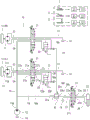
FIG. 1 is a circuit diagram showing a hydraulic circuit according to an embodiment;
fig. 2 is a circuit diagram showing a hydraulic circuit according to a modification.
Detailed Description
Fig. 1 is a circuit diagram showing a hydraulic circuit 10 according to an embodiment. The hydraulic circuit 10 shown in fig. 1 is mounted on a construction machine (particularly, a small-sized construction machine). Although not shown in detail, the construction machine includes a working device attached to a vehicle body, and performs a required work by operating the working device. The construction machine is a crawler vehicle equipped with a pair of left and right crawlers (crawlers), and is self-propelled. Examples of such a construction machine include a shovel car (shovel car) and a crane car (crane).
The hydraulic circuit 10 includes one or more first actuators 11 and one or more second actuators 12. Alternatively, the hydraulic circuit 10 drives one or more first actuators 11 and one or more second actuators 12 provided in the construction machine. In fig. 1, only one second actuator 12 is illustrated for simplicity. The actuators 11 and 12 are hydraulic actuators.
The operator's station of the construction machine is provided with one or more first manipulators 2 and one or more second manipulators 3 operated by an operator. The one or more first operators 2 correspond to the one or more first actuators 11, respectively. When a certain first actuator 2 is operated, the corresponding first actuator 11 is operated in the operating direction corresponding to the operation direction. The same applies to the relationship between the one or more second operators 3 and the second actuators 12.
For example only, the first actuator 11 is a travel actuator, and the second actuator 12 is a work device actuator.
In this case, the one or more first actuators 11 include a left travel motor 11L that drives the left starter wheel 1L provided in the left crawler belt and a right travel motor 11R that drives the right starter wheel 1R provided in the right crawler belt. Each first actuator 11 is a hydraulic motor that is rotatable in two directions (forward direction and reverse direction), and includes a pair of supply and discharge ports 11a and 11 b.
In the case where the working machine is an excavator, the one or more second actuators 12 include: a swing motor that swings the working device together with the cab, an arm cylinder that drives an arm provided in the working device, a bucket cylinder that drives a bucket provided in the working device, and the like. Fig. 1 shows a double acting hydraulic cylinder having two supply/discharge ports 12a and 12b as an example of the second actuator 12.
The one or more first operators 2 include a left travel operator 2L for rotating the left travel motor 11L and the left starter wheel 1L in the forward direction or the backward direction, and a right travel operator 2R for rotating the right travel motor 11R and the right starter wheel 1R in the forward direction or the backward direction. For example, the first travel operator 2 is of a pedal (pedal) type, and the second work implement operator 3 is of a lever (lever) type. This allows the operator to simultaneously operate the first manipulator 2 and the second manipulator 3 with hands and feet.
The construction machine may be equipped with a control device attached to the hydraulic circuit 10 (in other words, the construction machine may be equipped with a hydraulic system including the hydraulic circuit 10 and the control device attached thereto). The control device may electronically control the operation of the hydraulic components constituting the hydraulic circuit 10 based on the output of a sensor that detects the operation amount and/or the operation direction of each of the operators 2 and 3.
The hydraulic circuit 10 includes: the pump 13, the tank 14, the first pump line 15, the second pump line 16, the tank line 17, one or more first direction switching valves 21, one or more pressure compensating valves 22, one or more pairs of first supply and discharge lines 23, 24, one or more second direction switching valves 31, a priority valve 32, and one or more pairs of second supply and discharge lines 33, 34.
The pump 13 sucks in the hydraulic oil stored in the oil tank 14 and discharges the pressurized oil from the discharge port 13 a. The pump 13 is a source of pressurized oil for the actuators 11, 12.
A first direction switching valve 21, a pressure compensating valve 22, a pair of first supply and discharge lines 23, 24 and a first actuator 11 constitute a module. In each module, the first direction switching valve 21 has a pump port 21p and a pair of supply and discharge ports 21a, 21 b. The pump port 21p is connected to the discharge port 13a of the pump 13 through the first pump line 15. The supply/discharge port 21a is connected to the supply/discharge port 11a of the corresponding first actuator 11 through a supply/discharge line 23, and the supply/discharge port 21b is connected to the supply/discharge port 11b of the corresponding first actuator 11 through a supply/discharge line 24. The first direction switching valve 21 further has a tank port 21t, and the tank port 21t is connected to the tank 14 through a tank line 17 (the same applies to other tank ports described later).
When the first actuator 11 is operated, the pump port 21p is connected to either of the supply and discharge ports 21a and 21 b. This "connection" includes not only communication between ports completed in the first direction switching valve 21 but also connection via an oil passage outside the first direction switching valve 21.
In this regard, in the present embodiment, the first direction switching valve 21 further includes a primary port 21q and a secondary port 21 r. In each module, the primary port 21q of the first direction switching valve 21 is connected to the primary port 22a of the corresponding pressure compensating valve 22 via a primary compensating line 25 disposed outside the first direction switching valve 21. The secondary port 22b of the pressure compensation valve 22 is connected to the corresponding secondary port 21r of the first direction switching valve 21 via a secondary compensation line 26 disposed outside the first direction switching valve 21. When the first actuator 11 is operated, the pump port 21p communicates with the primary port 21q in the first direction switching valve 21 regardless of the operation direction. The secondary port 21r communicates with either one of the supply and discharge ports 21a, 21b in the first direction switching valve 21 according to the operation direction. The pump port 21p is connected to either of the supply and discharge ports 21a and 21b via a primary port 21q, a corresponding primary compensation line 25, a corresponding pressure compensation valve 22, a corresponding secondary compensation line 26, and a secondary port 21 r.
The second pump line 16 branches off from the first pump line 15. A priority valve 32 is provided on the second pump line 16. The second pump line 16 includes an upstream portion 16a connecting the first pump line 15 with the inlet port 32a of the priority valve 32 and a downstream portion 16b connecting with the outlet port 32b of the priority valve 32.
A second direction switching valve 31, a pair of second supply and discharge lines 33, 34 and a second actuator 12 constitute a module. In each module, the second direction switching valve 31 has a pump port 31p and a pair of supply and discharge ports 31a, 31 b. The pump port 31p is connected to the outlet port 32b of the priority valve 32 through the downstream portion 16b of the second pump line 16. In other words, the second pump line 16 branches off from the first pump line 15 and is connected to the pump port 31p of the second direction switching valve 31. The supply/discharge port 31a is connected to the supply/discharge port 12a of the second actuator 12 via a second supply/discharge line 33, and the supply/discharge port 31b is connected to the supply/discharge port 12b of the second actuator 12 via a second supply/discharge line 34. When the second actuator 12 is a double-acting hydraulic cylinder, a poppet valve (poppet) or a line for returning the hydraulic oil from the tank 14 may be provided in one of the supply and discharge lines 33 and 34 connected to the rod (rod) -side oil chamber.
The priority valve 32 is configured to fully open the second pump line 16 when a differential pressure between the discharge pressure of the pump 13 and the load pressure of the first actuator 11 is greater than a set value. When the differential pressure is smaller than the set value, the priority valve 32 is configured to reduce the opening degree of the second pump line 16 as the differential pressure is smaller. Here, the "differential pressure" refers to a pressure value obtained by subtracting the load pressure of the first actuator 11 from the discharge pressure of the pump 13. In short, if the load pressure of the first actuator 11 is high, the second pump line 16 is throttled by the priority valve 32.
In the present embodiment, the priority valve 32 that performs the above-described function is configured in a mechanical and hydraulic manner, and electronic control is not applied to the operation of the priority valve 32 as much as possible. For example, the priority valve 32 includes a valve plate that changes the opening degree of the second pump line 16, and a spring 32c that biases the valve plate in the closing direction. The "set value" is adjusted by the spring force exerted by the spring 32 c. The hydraulic pressure of the hydraulic oil flowing through the upstream portion 16a of the second pump line 16 (i.e., the discharge pressure of the pump 13) acts in the opening direction of the valve sheet. On the other hand, the load pressure of the first actuator 11 acts on the valve sheet in the closing direction. To supply the load pressure to the priority valve 32, the priority valve 32 is connected to the secondary compensation line 26 through the signal pressure supply line 18. The signal pressure supply line 18 branches off from the secondary compensating line 26 and is connected to a priority valve 32. Thus, the hydraulic pressure flowing through the secondary compensation line 26 is connected to the priority valve 32 as the load pressure of the first actuator 11. When the first actuator 11 is plural, the signal pressure supply line 18 includes a plurality of branch portions 18a extending from the plurality of secondary compensating lines 26, respectively, and a common portion 18b connected to the priority valve 32 in such a manner that the branch portions 18a are integrated into one system. Although the second pump line 16 is shown in a state in which the priority valve 32 is in the neutral state (the stopped state of the pump 13), this is merely an example, and the second pump line 16 may be opened at a small opening degree.
The operation of the hydraulic circuit 10 configured as described above will be described. The first direction switching valve 21 is a three-position direction switching valve. The valve position is changed according to the operation of the first operator 2, and the communication state (function) of the port is switched. The switching may be performed by using a control pressure or electronic control (the same applies to the second direction switching valve 31).
When the first operator 2 is not operated, the first direction switching valve 21 is located at the neutral position (see the center function of fig. 1). The pair of supply/ discharge ports 21a, 21b are each connected to the tank port 21t, and the remaining three ports 21p, 21q, 21r are blocked. Therefore, the supply of the pressure oil to the first actuator 11 is stopped, and the starting wheel 1 is stopped.
When the first operator 2 is operated in the first direction, the first direction switching valve 21 is positioned at the first position (see the upper function of fig. 1), the pump port 21p is connected to the primary port 21q, the secondary port 21r is connected to the supply/discharge port 21a, and the tank port 21t is connected to the supply/discharge port 21 b. The pressure oil from the pump 13 is supplied to the supply and discharge port 11a of the first actuator 11 through the pressure compensating valve 22. For example, the starter wheel 1 rotates in the forward direction (counterclockwise when viewed from the left side) to advance the vehicle.
When the first operator 2 is operated in the second direction, the first direction switching valve 21 is positioned at the second position (see the lower function of the drawing), the pump port 21p is connected to the primary port 21q, the secondary port 21r is connected to the supply/discharge port 21b, and the tank port 21t is connected to the supply/discharge port 21 a. The pressure oil from the pump 13 is supplied to the supply and discharge port 11b of the first actuator 11 through the pressure compensating valve 22. For example, the starter wheel 1 rotates in a reverse direction (clockwise when viewed from the left side) to reverse the vehicle.
Regardless of the operation direction of the first operator 2, the pump port 21p communicates with the primary port 21q when the first operator 2 operates. The pressurized oil from the pump 13 (once passed through the first direction switching valve 21) is input to the secondary port 21r of the first direction switching valve 21 through the primary compensation line 25, the pressure compensation valve 22, and the secondary compensation line 26. Therefore, the load pressure of the first actuator 11 (the oil pressure in the secondary compensation line 26, the secondary pressure of the pressure compensation valve 22) is supplied to the priority valve 32. Thereby, the valve piece of the priority valve 32 is also biased in the closing direction by the biasing force of the spring.
On the other hand, if the first operating device 2 is not operated, the load pressure is not supplied to the priority valve 32. The pressurized oil from the pump 13 is supplied to the upstream portion 16a of the second pump line 16. The hydraulic pressure (i.e., the discharge pressure of the pump 13) flowing through the upstream portion 16a acts on the valve sheet of the priority valve 32. The pressure difference between the discharge pressure and the load pressure of the pump 13 exceeds a set value adjusted by the spring force of the spring, and therefore the priority valve 32 is fully opened. The pressure oil from the pump 13 is supplied to the second direction switching valve 31 through the upstream portion 16a, the priority valve 32, and the downstream portion 16 b.
The second direction switching valve 31 is a three-position direction switching valve. The valve position is changed in accordance with the operation of the second operator 3, and the communication state (function) of the port is switched.
When the second operator 3 is not operated, the second direction switching valve 31 is located at the center position, and the four ports 31a, 31b, 31p, and 31t are blocked. The supply of the pressurized oil to the second actuator 12 is stopped, and the second actuator 12 is stopped. When the second operator 3 is operated in the first direction, the second direction switching valve 31 is located at the first position (see the upper function of fig. 1). The pump port 31p is connected to the supply/discharge port 31a, and the tank port 31t is connected to the supply/discharge port 31 b. The hydraulic oil from the pump 13 is supplied to the supply/discharge port 12a of the second actuator 12, and the working device is operated in one direction. When the second operator 3 is operated in the second direction, the second direction switching valve 31 is positioned at the second position (see lower functional reference in fig. 1), the pump port 31p is connected to the supply/discharge port 31b, and the tank port 31t is connected to the supply/discharge port 31 a. The pressure oil from the pump 13 is supplied to the supply/discharge port 12b of the second actuator 12, and the working device is operated in the direction opposite to the aforementioned direction.
When the first operator 2 and the second operator 3 are simultaneously operated, the valve positions of the first direction switching valve 21 and the second direction switching valve 31 are switched from the neutral positions. The valve position of the first direction switching valve 21 is switched from the neutral position, and thereby the load pressure of the first actuator 11 is supplied to the priority valve 32 through the signal pressure supply line 18. In this example, the discharge pressure of the pump 13 acts in the opening direction, and the spring force of the spring 32c and the load of the first actuator 11 act in the closing direction on the valve sheet of the priority valve 32. When the differential pressure between the discharge pressure of the pump 13 and the load pressure of the first actuator 11 is smaller than a set value (adjusted by the spring force of the spring), the opening degree of the second pump line 16 defined by the position of the valve sheet is small.
Thus, the throttle amount of the second pump line 16 set in the priority valve 32 is larger as the load of the first actuator 11 is larger. This preferentially ensures the flow rate flowing through the first direction switching valve 21 and the first actuator 11. Therefore, a decrease in the operating speed of the first actuator 11 on the large load side can be suppressed.
In the present embodiment, the first actuator 11 is a travel motor, and the second actuator 12 is a hydraulic actuator for a working device. When the travel operation and the operation of the working device are performed simultaneously, it is possible to suppress a decrease in both the travel speed and the operating speed of the working device, and to maintain the travel speed high.
In this way, in a so-called single pump system, it is possible to suppress both of the operating speeds of the different types of actuators from decreasing. In the present embodiment, electrical detection of the operation amount of the first operator 2, the operation amount of the second operator 3, the load pressure of the first actuator 11, and the load pressure of the second actuator 12 is not required for this implementation, and therefore complicated valve control referring to the detection results of these parameters is also not required. Instead, a priority valve 32 for changing the opening degree of the second pump line 16 is provided in the second pump line 16 branched from the first pump line 15, and a signal pressure supply line 18 for supplying the load pressure of the first actuator 11 to the priority valve 32 as the control pressure is provided. With this configuration, a system capable of suppressing a decrease in the operating speeds of the two actuators during simultaneous operation can be easily configured.
The embodiments of the present invention have been described above, but the above-described configuration can be appropriately modified within the scope of the present invention. Fig. 2 shows a modified hydraulic circuit 10A, and the pressure compensating valve 22 (see also fig. 1) may be omitted. In the case where the pressure compensating valve 22 is omitted, the configuration of the first direction switching valve 21 may be the same as that of the above-described embodiment as in the modification shown in fig. 2, or may be changed. When the first direction switching valve 21 has the same configuration as that of the above-described embodiment, the connection oil passage 25A connects the primary port 21q and the secondary port 21r in place of the primary compensation line 25 and the secondary compensation line 26 (see also fig. 1). The signal pressure supply line 18 branches off from the connection oil passage 25A and is connected to the priority valve 32. The hydraulic pressure flowing through the connection oil passage 25A is supplied to the priority valve 32 as the load pressure of the first actuator (traveling motor). In this modification, it is possible to suppress a decrease in both the traveling speed and the operating speed of the working device during the simultaneous operation, and to maintain the traveling speed high.
The first actuator may be a work implement, and the second actuator may be a travel implement. In this case, when the load pressure of the work implement is high during the simultaneous operation, the flow rate to the work implement can be preferentially secured, and the operation speed of the work implement can be maintained high.
Description of the symbols:
10 oil pressure circuit
11 first actuator
12 second actuator
13 Pump
15 first pump line
16 second pump line
18 signal pressure supply line
21 first direction switching valve
21a, 21b supply and discharge port
21p pump port
21q Primary Port
21r secondary port
22 pressure compensating valve
26 secondary compensating pipeline
31 second direction switching valve
31a, 31b supply and discharge ports
31p pump port
32 priority valve.
Claims (3)
1. A hydraulic circuit for a construction machine, comprising:
a first actuator;
a second actuator;
a pump;
a first direction switching valve having a pair of supply/discharge ports connected to a pump port and the first actuator, the first direction switching valve connecting the pump port to one of the supply/discharge ports when an operation to operate the first actuator is performed;
a second directional control valve having a pair of supply/discharge ports connected to a pump port and the second actuator, the second directional control valve connecting the pump port to one of the supply/discharge ports when the second actuator is operated;
a first pump line connecting a discharge port of the pump and the pump port of the first direction switching valve;
a second pump line connecting a discharge port of the pump and the pump port of the second direction switching valve; and
a priority valve disposed on the second pump line;
the priority valve is configured to: fully opening the second pump line when a differential pressure between a discharge pressure of the pump and a load pressure of the first actuator is greater than a set value; when the differential pressure is smaller than the set value, the smaller the differential pressure, the smaller the opening degree of the second pump line.
2. The hydraulic circuit of a construction machine according to claim 1,
the pressure compensation valve is arranged corresponding to the first actuator;
the first direction switching valve further has a primary port connected to a primary side of the pressure compensating valve and a secondary port connected to a secondary side of the pressure compensating valve through a secondary compensating line;
when the first actuator is operated, the pump port of the first direction switching valve communicates with the primary port and the secondary port communicates with one of the supply and discharge ports of the first direction switching valve, and the pump port is connected to one of the supply and discharge ports through the primary port, the pressure compensating valve, and the secondary port;
the priority valve is connected to the secondary compensation line via a signal pressure supply line, and the working oil pressure flowing through the secondary compensation line is supplied to the priority valve as the load pressure of the first actuator.
3. The hydraulic circuit of a construction machine according to claim 1 or 2,
the first actuator is a travel actuator, and the second actuator is an actuator for operating a working device.
Applications Claiming Priority (3)
| Application Number | Priority Date | Filing Date | Title |
|---|---|---|---|
| JP2018-151071 | 2018-08-10 | ||
| JP2018151071A JP6964052B2 (en) | 2018-08-10 | 2018-08-10 | Hydraulic circuit of construction machinery |
| PCT/JP2019/030113 WO2020031816A1 (en) | 2018-08-10 | 2019-08-01 | Construction-machinery hydraulic circuit |
Publications (1)
| Publication Number | Publication Date |
|---|---|
| CN112424485A true CN112424485A (en) | 2021-02-26 |
Family
ID=69414219
Family Applications (1)
| Application Number | Title | Priority Date | Filing Date |
|---|---|---|---|
| CN201980048928.8A Pending CN112424485A (en) | 2018-08-10 | 2019-08-01 | Hydraulic circuit for construction machine |
Country Status (5)
| Country | Link |
|---|---|
| US (1) | US11131080B2 (en) |
| JP (1) | JP6964052B2 (en) |
| CN (1) | CN112424485A (en) |
| DE (1) | DE112019004044T5 (en) |
| WO (1) | WO2020031816A1 (en) |
Families Citing this family (3)
| Publication number | Priority date | Publication date | Assignee | Title |
|---|---|---|---|---|
| US11713775B2 (en) * | 2020-08-18 | 2023-08-01 | Deere & Company | Agricultural implements and hydraulic circuits therefor incorporating one or more priority valves |
| WO2023176732A1 (en) * | 2022-03-15 | 2023-09-21 | 川崎重工業株式会社 | Hydraulic drive device |
| WO2023176733A1 (en) * | 2022-03-15 | 2023-09-21 | 川崎重工業株式会社 | Hydraulic drive device |
Citations (6)
| Publication number | Priority date | Publication date | Assignee | Title |
|---|---|---|---|---|
| JPS58153829A (en) * | 1982-03-08 | 1983-09-13 | Kobe Steel Ltd | Oil-pressure circuit for oil-pressure shovel |
| CN1224808A (en) * | 1997-12-17 | 1999-08-04 | 胡斯可国际股份有限公司 | Hydraulic control valve system with load sensing priority |
| CN103649554A (en) * | 2011-03-15 | 2014-03-19 | 胡斯可国际股份有限公司 | System for allocating fluid from multiple pumps to a plurality of hydraulic functions on a priority basis |
| CN105201944A (en) * | 2015-09-25 | 2015-12-30 | 广西柳工机械股份有限公司 | Flow enlarging valve and hydraulic steering system |
| US20170274930A1 (en) * | 2014-11-24 | 2017-09-28 | Parker-Hannifin Corporation | System architectures for steering and work functions in a wheel |
| JP2017190799A (en) * | 2016-04-11 | 2017-10-19 | キャタピラー エス エー アール エル | Hydraulic circuit of work machine |
Family Cites Families (1)
| Publication number | Priority date | Publication date | Assignee | Title |
|---|---|---|---|---|
| JP2948064B2 (en) | 1993-09-06 | 1999-09-13 | 日立建機株式会社 | Hydraulic drive for construction machinery |
-
2018
- 2018-08-10 JP JP2018151071A patent/JP6964052B2/en active Active
-
2019
- 2019-08-01 CN CN201980048928.8A patent/CN112424485A/en active Pending
- 2019-08-01 WO PCT/JP2019/030113 patent/WO2020031816A1/en active Application Filing
- 2019-08-01 DE DE112019004044.8T patent/DE112019004044T5/en active Pending
- 2019-08-01 US US17/262,838 patent/US11131080B2/en active Active
Patent Citations (6)
| Publication number | Priority date | Publication date | Assignee | Title |
|---|---|---|---|---|
| JPS58153829A (en) * | 1982-03-08 | 1983-09-13 | Kobe Steel Ltd | Oil-pressure circuit for oil-pressure shovel |
| CN1224808A (en) * | 1997-12-17 | 1999-08-04 | 胡斯可国际股份有限公司 | Hydraulic control valve system with load sensing priority |
| CN103649554A (en) * | 2011-03-15 | 2014-03-19 | 胡斯可国际股份有限公司 | System for allocating fluid from multiple pumps to a plurality of hydraulic functions on a priority basis |
| US20170274930A1 (en) * | 2014-11-24 | 2017-09-28 | Parker-Hannifin Corporation | System architectures for steering and work functions in a wheel |
| CN105201944A (en) * | 2015-09-25 | 2015-12-30 | 广西柳工机械股份有限公司 | Flow enlarging valve and hydraulic steering system |
| JP2017190799A (en) * | 2016-04-11 | 2017-10-19 | キャタピラー エス エー アール エル | Hydraulic circuit of work machine |
Also Published As
| Publication number | Publication date |
|---|---|
| JP6964052B2 (en) | 2021-11-10 |
| WO2020031816A1 (en) | 2020-02-13 |
| US20210140144A1 (en) | 2021-05-13 |
| US11131080B2 (en) | 2021-09-28 |
| DE112019004044T5 (en) | 2021-05-06 |
| JP2020026828A (en) | 2020-02-20 |
Similar Documents
| Publication | Publication Date | Title |
|---|---|---|
| JP4799624B2 (en) | Hydraulic drive control device | |
| KR101820324B1 (en) | Hydraulic circuit for pipe layer | |
| US7350353B2 (en) | Hydraulic circuit | |
| JP2007064455A (en) | Hydraulic pressure control device for working machine | |
| CN112424485A (en) | Hydraulic circuit for construction machine | |
| CN106837902B (en) | Hydraulic drive device | |
| CN109563854B (en) | Valve device and fluid pressure system equipped with the same | |
| EP1726723B1 (en) | Working machine | |
| JP6776334B2 (en) | Excavator and control valve for excavator | |
| US11078646B2 (en) | Shovel and control valve for shovel | |
| US20080229738A1 (en) | Hydraulic circuit to prevent bucket separation from bucket rest during traveling of heavy equipment | |
| JP6196567B2 (en) | Hydraulic drive system for construction machinery | |
| JP6514522B2 (en) | Hydraulic drive system of unloading valve and hydraulic shovel | |
| JP4106011B2 (en) | Hydraulic circuit and junction valve | |
| CN107532619B (en) | Fluid pressure control device | |
| CN108884843B (en) | Excavator and control valve for excavator | |
| JP2007120512A (en) | Hydraulic control device for working machine | |
| JP2019183972A (en) | Hydraulic circuit of working vehicle | |
| US11242671B2 (en) | Hydraulic circuit of construction machine | |
| JP4926627B2 (en) | Electric oil system | |
| JP2005140153A (en) | Hydraulic control device for construction machine | |
| US11313104B2 (en) | Control system for construction machinery | |
| JP2012149554A (en) | Traveling drive circuit device for wheel type traveling working vehicle | |
| JP2023076907A (en) | Hydraulic system of industrial vehicle | |
| JP2023069621A (en) | Hydraulic system of industrial vehicle |
Legal Events
| Date | Code | Title | Description |
|---|---|---|---|
| PB01 | Publication | ||
| PB01 | Publication | ||
| SE01 | Entry into force of request for substantive examination | ||
| SE01 | Entry into force of request for substantive examination | ||
| WD01 | Invention patent application deemed withdrawn after publication | ||
| WD01 | Invention patent application deemed withdrawn after publication |
Application publication date: 20210226 |