EP1972593A1 - Elevator device - Google Patents
Elevator device Download PDFInfo
- Publication number
- EP1972593A1 EP1972593A1 EP06702659A EP06702659A EP1972593A1 EP 1972593 A1 EP1972593 A1 EP 1972593A1 EP 06702659 A EP06702659 A EP 06702659A EP 06702659 A EP06702659 A EP 06702659A EP 1972593 A1 EP1972593 A1 EP 1972593A1
- Authority
- EP
- European Patent Office
- Prior art keywords
- car
- guide rails
- elevator
- guide
- safety gear
- Prior art date
- Legal status (The legal status is an assumption and is not a legal conclusion. Google has not performed a legal analysis and makes no representation as to the accuracy of the status listed.)
- Withdrawn
Links
Images



Classifications
-
- B—PERFORMING OPERATIONS; TRANSPORTING
- B66—HOISTING; LIFTING; HAULING
- B66B—ELEVATORS; ESCALATORS OR MOVING WALKWAYS
- B66B5/00—Applications of checking, fault-correcting, or safety devices in elevators
- B66B5/02—Applications of checking, fault-correcting, or safety devices in elevators responsive to abnormal operating conditions
- B66B5/16—Braking or catch devices operating between cars, cages, or skips and fixed guide elements or surfaces in hoistway or well
- B66B5/18—Braking or catch devices operating between cars, cages, or skips and fixed guide elements or surfaces in hoistway or well and applying frictional retarding forces
- B66B5/22—Braking or catch devices operating between cars, cages, or skips and fixed guide elements or surfaces in hoistway or well and applying frictional retarding forces by means of linearly-movable wedges
-
- B—PERFORMING OPERATIONS; TRANSPORTING
- B66—HOISTING; LIFTING; HAULING
- B66B—ELEVATORS; ESCALATORS OR MOVING WALKWAYS
- B66B7/00—Other common features of elevators
- B66B7/02—Guideways; Guides
- B66B7/04—Riding means, e.g. Shoes, Rollers, between car and guiding means, e.g. rails, ropes
- B66B7/041—Riding means, e.g. Shoes, Rollers, between car and guiding means, e.g. rails, ropes including active attenuation system for shocks, vibrations
- B66B7/042—Riding means, e.g. Shoes, Rollers, between car and guiding means, e.g. rails, ropes including active attenuation system for shocks, vibrations with rollers, shoes
-
- B—PERFORMING OPERATIONS; TRANSPORTING
- B66—HOISTING; LIFTING; HAULING
- B66B—ELEVATORS; ESCALATORS OR MOVING WALKWAYS
- B66B9/00—Kinds or types of lifts in, or associated with, buildings or other structures
- B66B9/003—Kinds or types of lifts in, or associated with, buildings or other structures for lateral transfer of car or frame, e.g. between vertical hoistways or to/from a parking position
Definitions
- the present invention relates to an elevator apparatus equipped with a guide device and a safety gear device of an elevator car, which adapt to changes in the distance between guide rails.
- guide rails are installed in a shaft, a car ascends and descends in the shaft by being guided by the guide rails, and the car is equipped with a pair of safety gear devices mounted opposite to the guide rails.
- there are self-propelled elevators which move in a plurality of shafts (refer to Patent Documents 1 and 2, for example).
- the guide rails provided in each of the plurality of shafts serve all cars, and hence it is necessary that the distance between the guide rails be the same in all of the shafts. Therefore, in a case where the plurality of shafts do not have the same width for reasons ascribed to the building side, in order to make the distance between the guide rails constant, it was necessary that in part of the shafts, the gap of the guide rails from the walls be increased. At this time, there has arisen the problem that in order to support loads applied to the guide rails, the supports of the guide rails from the wall side must be robust.
- An elevator apparatus is equipped with a car which ascends and descends in an elevator shaft, a pair of guide rails which are provided in the elevator shaft and whose mutual distance changes partially, a car guide device which is provided in the car, can freely move forward and backward to any horizontal position with respect to the car, and constantly abuts against the guide rails by responding to changes in the mutual distance of the guide rails, and a safety gear device which is provided in the car, can freely move forward and backward to any horizontal position with respect to the car, is constantly opposed to the guide rails with equal spacing therefrom by responding to changes in the mutual distance of the guide rails, and brings the car to an emergency stop by grasping the guide rails during a fall of the car at an overspeed.
- an elevator apparatus is equipped with a car which ascends and descends in an elevator shaft, a pair of guide rails which are provided in the elevator shaft and whose mutual distance changes partially, a measuring device which measures the distance between the guide rails, a car guide device which is provided in the car, can freely move forward and backward to any horizontal position with respect to the car, and constantly abuts against the guide rails by responding to changes in the mutual distance of the guide rails, a safety gear device which is provided in the car, can freely move forward and backward to any horizontal position with respect to the car, is constantly opposed to the guide rails with equal spacing therefrom by responding to changes in the mutual distance of the guide rails, and brings the car to an emergency stop by grasping the guide rails during a fall of the car at an overspeed, and a controller which determines, from measurement results of the measuring device, the amounts of travel of the car guide device and the safety gear device in forward and backward movements.
- the elevator apparatus according to the present invention is such that the car guide device and the safety gear device are displaced by an actuator.
- the elevator apparatus is such that the elevator shaft comprises a plurality of shafts having different distances between the guide rails, and that the car is a self-propelled type and moves, ascends and descends in the plurality of elevator shafts.
- the elevator apparatus is such that the safety gear device is equipped with a wedge which grips the guide rails by moving upward, thereby to brake the guide rails, and an actuator portion which fixes the wedge downward during a normal run of the car and moves the wedge upward during a fall of the car at an overspeed.
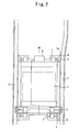
- Figure 1 is a front view which shows an elevator apparatus in Embodiment 1 of the present invention.
- Figure 2 is a diagram which shows an elevator apparatus in which the distance between guide rails is changed, the figure corresponding to Figure 1 .
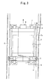
- Figure 3 is a diagram which shows the condition of a car approaching a place where the distance between guide rails is changed, the figure corresponding to Figure 2 .
- Figure 4 is a front view of an elevator apparatus in which the distance between guide rails is changed in a complex manner in Embodiment 1 of the present invention.
- Figure 5 is a front view of a safety gear device provided in the elevator apparatus in Embodiment 1 of the present invention.
- Figure 6 is a diagram which shows the condition in which the safety gear device has been actuated, the figure corresponding to Figure 5 .
- the reference numeral 1 denotes an elevator shaft
- the reference numeral 2 denotes a pair of right and left guide rails which are fixed to both side walls of the elevator shaft respectively via supports (not shown), and whose relative distance changes partially.
- the reference numeral 3 denotes a car which is provided between the pair of right and left guide rails 2 and ascends and descends in the elevator shaft 1.
- the reference numeral 4 denotes car guide devices, which are provided in an upper part and a lower part of the car 3 in a protruding manner in both right and left directions and guide the ascent and descent of the car 3.
- the reference numeral 5 denotes safety gear devices which are provided in a protruding manner in both right and left directions of the lower part of the car 3 and are each opposed to the pair of right and left guide rails 2.
- the safety gear devices bring the car 3 to an emergency stop by grasping both side surfaces of each of the pair of right and left guide rails 2 during a fall of the car 3 at an overspeed.
- the reference numeral 6 denotes measuring devices which are provided in the upper part and lower part of the car 3 and measure any time the relative distance of the guide rails 2 in the upper part and lower part of the car.
- the reference numeral 7 denotes actuators, which are each provided in the car guide devices 4 and the safety gear devices 5 and cause the car guide devices 4 and the safety gear devices 5 to freely move laterally.
- the reference numeral 8 denotes a controller which is connected by control cables to the measuring devices 6 and each of the actuators 7.
- the controller gives directions for the amounts of travel to the actuators 7 on the basis of measurement results of the distance between the guide rails obtained by the measuring devices 6 and input data, such as the speed of the car 3. That is, the controller 8 provides directions for the amounts of travel of each of the actuators 7 so that each of the car guide devices 4 constantly abuts against the pair of right and left guide rails 2 even when the car 3 passes a place where the relative distance of the guide rails 2 has changed, whereby the controller causes each of the car guide devices 4 to move forward and backward horizontally. Also, this ensures that the car 3 does not swing horizontally and that the posture of the car is prevented from becoming imbalanced. Similarly, the controller causes the safety gear devices 5 to be opposed to the pair of right and left guide rails 2 constantly with the same spacing.
- FIG. 2 and 3 An example of the operation of the elevator apparatus constructed as described above will be described by using Figures 2 and 3 .
- the car 3 is in the course of an ascent, and an extended portion 2a is provided on the upper right side of the guide rail 2 above the car 3.
- the upper right side of the measuring device 6 detects the extension of this area 2a and measures any time the distance between the guide rails. The measurement result is fed to the controller 8.
- the controller 8 determines the travels and timing of the car guide device 4 and the safety gear device 5 by adding other data on speed of the car 3 and the like.
- the controller 8 gives directions for the amounts of travel any time to the actuator 7.
- the upper right side of the car guide device 5 first moves any time to any position, and next, the right side of the safety gear device 5 and the lower right side of the car guide device 4 move to any position.
- the car guide device 4 can abut against the guide rails 2 constantly with a constant pressure. Therefore, the car 3 can ascend and descend at a prescribed position without swinging horizontally and with the posture not becoming imbalanced. Furthermore, because the safety gear device 5 can be opposed to the pair of right and left guide rails 2 always at a constant distance therefrom, the elevator apparatus can be made safe.
- this elevator apparatus it is possible to adapt to changes in the distance between the pair of right and left guide rails 2, and hence in a case where the accuracy of the vertical linearity of the wall surfaces of the shaft is low and the width is not vertically uniform, it becomes unnecessary to install the guide rails 2 accurately, with the guide rail 2 interval kept constant, by adjusting the installed dimensions of the guide rails 2 from the wall surfaces of the shaft. That is, it is possible to make it unnecessary to adjust the surfaces of supports which support the guide rails 2 from the wall surfaces or the positions of the mounting surfaces for the guide rail 2 surfaces and the ease with which the guide rails 2 are installed is improved.
- the construction of the safety gear device 5 is the same as described in Embodiment 1 of Patent Document WO2004/083090A1 .
- the reference numeral 5a denotes supports which are fixed to the car 3 side
- the reference numeral 5b denotes a pair of laterally symmetrical, right and left wedges, which are provided above the supports 5a, the guide rail 2 being positioned therebetween, and which can move vertically.
- Each of the pair of wedges 5b is provided with an inner side surface, which is a barking surface 5c opposed to both side surfaces of the guide rail 2, and an outer side surface which is inclined in such a manner that the thickness relative to the inner side surface decreases upward.
- the reference numeral 5d denotes a pair of laterally symmetrical wedge guide portions which are provided on the supports 5a in a standing manner, the pair of wedges 5b being positioned therebetween, and each of the wedge guide portions has an inclined surface which is opposed in parallel to the outer side surface of the wedge 5b.
- the reference numeral 5e denotes a pair of actuator portions, which are each provided between the pair of wedges 5b and the supports 5a.
- the pair of wedges 5b is each provided with a magnet 5f at a bottom end, and the pair of actuator portions 5e is each constituted by an electromagnet 5g opposed to the magnet 5f and an urging spring 5h.
- the electromagnets 5g of the pair of actuators 5e are energized and excited, attract the magnets 5f of the pair of wedges 5b and compress the urging springs 5h and fix the urging springs to the support 5a side.
- the braking surfaces 5c of the pair of wedges 5b are away from the guide rail 2.
- power to the electromagnets 5g is cut on the basis of an electrical signal indicating this and the electromagnets lose a magnetic force and the pair of wedges 5b are moved upward by the urging springs 5h.
- the braking surfaces 5c of the pair of wedges 5b grip both side surfaces of the guide rail 2, whereby braking is performed.
- the safety gear device 5 constructed as described above does not require a connection mechanism (a pull rod or the like) to a governor any more as in a conventional safety gear device, and the device can be simplified. Furthermore, because the safety gear device 5 operates in accordance with the directions of an electrical signal, it is possible to brake the car 3 in a short time compared to a conventional safety gear device after the detection of a speed abnormality of the car 3 and it is possible to shorten the braking distance. It is possible to readily actuate the pair of right and left safety gear devices in synchronization with each other and the car 3 can be braked in a stable manner. Furthermore, it is possible to prevent malfunctions due to the swings of the car 3 and the like.
- the controller 8 is caused to store beforehand a place where the distance between the pair of right and left guide rails 2 in the shaft has changed and information on the distance between the guide rails 2 and the like and each of the actuators 7 is operated on the basis of this information. As a result of this, a measuring device becomes unnecessary and the construction and control of the elevator apparatus can be simplified.
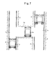
- FIG 7 is a sectional view of a shaft of an elevator apparatus in Embodiment 3 of the present invention.
- the reference numeral 3a denotes a car of a self-propelled elevator.
- the reference numeral 1a denotes two elevator shafts of self-propelled elevator, which have different distances between guide rails and in each of which a car 3a travels, ascends and descends.
- the reference numeral 1b denotes a communication passage which connects the two elevator shafts 1a, communication means which causes the cars 3a to move horizontally and travel between the two elevator shafts 1a.
- a safety gear device 5 has the same construction as described in Embodiment 1.
- the measuring device 6 can be made unnecessary.
- the controller 8 it is necessary only to add a construction which is such that in the communication passage 1b, the controller 8 is caused to recognize the distance between the guide rails 2 of the elevator shaft 1a to which the car is to be moved and in the communication passage 1b, the car guide device 4 and the safety gear device 5 are caused to move to any position.
- the construction and control of the elevator apparatus can be simplified.
- the present invention can be applied to guide rails guiding traveling things, in which there is a possibility that the distance between the guide rails changes.
Landscapes
- Engineering & Computer Science (AREA)
- Mechanical Engineering (AREA)
- Maintenance And Inspection Apparatuses For Elevators (AREA)
- Lift-Guide Devices, And Elevator Ropes And Cables (AREA)
- Types And Forms Of Lifts (AREA)
Abstract
Description
- The present invention relates to an elevator apparatus equipped with a guide device and a safety gear device of an elevator car, which adapt to changes in the distance between guide rails.
- In some conventional elevator apparatus, guide rails are installed in a shaft, a car ascends and descends in the shaft by being guided by the guide rails, and the car is equipped with a pair of safety gear devices mounted opposite to the guide rails.
Also, in some conventional elevator apparatus, there are self-propelled elevators which move in a plurality of shafts (refer toPatent Documents -
- [Patent Document 1]: Japanese Patent Laid-Open No.
2000-185885 - [Patent Document 2]: Japanese Patent Laid-Open No.
6-156939 - In conventional elevator apparatus, for guide rails which are fixed to wall surfaces of a shaft to guide the ascent and descent of a car, it was necessary that the mutual distance of the guide rails be vertically constant. In general, however, the accuracy of the vertical linearity of the wall surfaces of a shaft is low and the width is not vertically uniform. For this reason, it is general practice to install the guide rails accurately, with the guide rail interval kept constant, by adjusting the installed dimensions of the guide rails from the wall surfaces of a shaft. This adjustment of the installed dimensions of the guide rails is performed by adjusting the surfaces of supports which support the guide rails from the wall surfaces or the positions of the mounting surfaces for the guide rail surfaces, posing the problem that the installation time is enormous.
In the self-propelled elevator of the conventional elevator apparatus shown inPatent Document 2, the guide rails provided in each of the plurality of shafts serve all cars, and hence it is necessary that the distance between the guide rails be the same in all of the shafts. Therefore, in a case where the plurality of shafts do not have the same width for reasons ascribed to the building side, in order to make the distance between the guide rails constant, it was necessary that in part of the shafts, the gap of the guide rails from the walls be increased. At this time, there has arisen the problem that in order to support loads applied to the guide rails, the supports of the guide rails from the wall side must be robust. - An elevator apparatus according to the present invention is equipped with a car which ascends and descends in an elevator shaft, a pair of guide rails which are provided in the elevator shaft and whose mutual distance changes partially, a car guide device which is provided in the car, can freely move forward and backward to any horizontal position with respect to the car, and constantly abuts against the guide rails by responding to changes in the mutual distance of the guide rails, and a safety gear device which is provided in the car, can freely move forward and backward to any horizontal position with respect to the car, is constantly opposed to the guide rails with equal spacing therefrom by responding to changes in the mutual distance of the guide rails, and brings the car to an emergency stop by grasping the guide rails during a fall of the car at an overspeed.
- Also, an elevator apparatus according to the present invention is equipped with a car which ascends and descends in an elevator shaft, a pair of guide rails which are provided in the elevator shaft and whose mutual distance changes partially, a measuring device which measures the distance between the guide rails, a car guide device which is provided in the car, can freely move forward and backward to any horizontal position with respect to the car, and constantly abuts against the guide rails by responding to changes in the mutual distance of the guide rails, a safety gear device which is provided in the car, can freely move forward and backward to any horizontal position with respect to the car, is constantly opposed to the guide rails with equal spacing therefrom by responding to changes in the mutual distance of the guide rails, and brings the car to an emergency stop by grasping the guide rails during a fall of the car at an overspeed, and a controller which determines, from measurement results of the measuring device, the amounts of travel of the car guide device and the safety gear device in forward and backward movements.
- The elevator apparatus according to the present invention is such that the car guide device and the safety gear device are displaced by an actuator.
- The elevator apparatus according to the present invention is such that the elevator shaft comprises a plurality of shafts having different distances between the guide rails, and that the car is a self-propelled type and moves, ascends and descends in the plurality of elevator shafts.
- The elevator apparatus according to the present invention is such that the safety gear device is equipped with a wedge which grips the guide rails by moving upward, thereby to brake the guide rails, and an actuator portion which fixes the wedge downward during a normal run of the car and moves the wedge upward during a fall of the car at an overspeed.
- According to the present invention, it is possible to adapt to changes in the distance between guide rails and to improve the ride comfort and safety of an elevator car and to improve also the ease with which the guide rails are installed.
-
-
Figure 1 is a front view which shows an elevator apparatus inEmbodiment 1 of the present invention; -
Figure 2 is a diagram which shows an elevator apparatus in which the distance between guide rails is changed, the figure corresponding toFigure 1 ; -
Figure 3 is a diagram which shows the condition of a car approaching a place where the distance between guide rails is changed, the figure corresponding toFigure 2 ; -
Figure 4 is a front view of an elevator apparatus in which the distance between guide rails is changed in a complex manner inEmbodiment 1 of the present invention; -
Figure 5 is a front view of a safety gear device provided in the elevator apparatus inEmbodiment 1 of the present invention; -
Figure 6 is a diagram which shows the condition in which the safety gear device has been actuated, the figure corresponding toFigure 1 ; and -
Figure 7 is a sectional view of a shaft of an elevator apparatus inEmbodiment 3 of the present invention. -
- 1
- Shaft
- 1b
- Communication passage
- 2
- Guide rail
- 3
- Car
- 4
- Car guide device
- 5
- Safety gear device
- 5a
- Support of safety gear device
- 5b
- Wedge
- 5c
- Braking surface
- 5d
- Wedge guide portion
- 5e
- Actuator portion
- 5f
- Magnet
- 5g
- Electromagnet
- 5h
- Spring
- 6
- Measuring device
- 7
- Actuator
- 8
- Controller
-
Figure 1 is a front view which shows an elevator apparatus inEmbodiment 1 of the present invention.Figure 2 is a diagram which shows an elevator apparatus in which the distance between guide rails is changed, the figure corresponding toFigure 1 .Figure 3 is a diagram which shows the condition of a car approaching a place where the distance between guide rails is changed, the figure corresponding toFigure 2 .Figure 4 is a front view of an elevator apparatus in which the distance between guide rails is changed in a complex manner inEmbodiment 1 of the present invention.Figure 5 is a front view of a safety gear device provided in the elevator apparatus inEmbodiment 1 of the present invention.Figure 6 is a diagram which shows the condition in which the safety gear device has been actuated, the figure corresponding toFigure 5 .
In the figures, thereference numeral 1 denotes an elevator shaft, and thereference numeral 2 denotes a pair of right and left guide rails which are fixed to both side walls of the elevator shaft respectively via supports (not shown), and whose relative distance changes partially. Thereference numeral 3 denotes a car which is provided between the pair of right andleft guide rails 2 and ascends and descends in theelevator shaft 1. Thereference numeral 4 denotes car guide devices, which are provided in an upper part and a lower part of thecar 3 in a protruding manner in both right and left directions and guide the ascent and descent of thecar 3. Thereference numeral 5 denotes safety gear devices which are provided in a protruding manner in both right and left directions of the lower part of thecar 3 and are each opposed to the pair of right and left guide rails 2. The safety gear devices bring thecar 3 to an emergency stop by grasping both side surfaces of each of the pair of right andleft guide rails 2 during a fall of thecar 3 at an overspeed. Thereference numeral 6 denotes measuring devices which are provided in the upper part and lower part of thecar 3 and measure any time the relative distance of theguide rails 2 in the upper part and lower part of the car. Thereference numeral 7 denotes actuators, which are each provided in thecar guide devices 4 and thesafety gear devices 5 and cause thecar guide devices 4 and thesafety gear devices 5 to freely move laterally. Thereference numeral 8 denotes a controller which is connected by control cables to themeasuring devices 6 and each of theactuators 7. The controller gives directions for the amounts of travel to theactuators 7 on the basis of measurement results of the distance between the guide rails obtained by the measuringdevices 6 and input data, such as the speed of thecar 3. That is, thecontroller 8 provides directions for the amounts of travel of each of theactuators 7 so that each of thecar guide devices 4 constantly abuts against the pair of right andleft guide rails 2 even when thecar 3 passes a place where the relative distance of theguide rails 2 has changed, whereby the controller causes each of thecar guide devices 4 to move forward and backward horizontally. Also, this ensures that thecar 3 does not swing horizontally and that the posture of the car is prevented from becoming imbalanced. Similarly, the controller causes thesafety gear devices 5 to be opposed to the pair of right andleft guide rails 2 constantly with the same spacing. - An example of the operation of the elevator apparatus constructed as described above will be described by using
Figures 2 and3 . InFigures 2 and3 , thecar 3 is in the course of an ascent, and anextended portion 2a is provided on the upper right side of theguide rail 2 above thecar 3.
First, when thecar 3 is approaching thearea 2a where the right side of the pair of right andleft guide rails 2 has been extended, the upper right side of the measuringdevice 6 detects the extension of thisarea 2a and measures any time the distance between the guide rails. The measurement result is fed to thecontroller 8. Next, thecontroller 8 determines the travels and timing of thecar guide device 4 and thesafety gear device 5 by adding other data on speed of thecar 3 and the like. Next, thecontroller 8 gives directions for the amounts of travel any time to theactuator 7. At the indication, as shown inFigure 3 , the upper right side of thecar guide device 5 first moves any time to any position, and next, the right side of thesafety gear device 5 and the lower right side of thecar guide device 4 move to any position. - According to the elevator apparatus constructed as described above, even in a case where the
car 3 passes a place where the distance between the pair of right andleft guide rails 2 has changed, thecar guide device 4 can abut against theguide rails 2 constantly with a constant pressure. Therefore, thecar 3 can ascend and descend at a prescribed position without swinging horizontally and with the posture not becoming imbalanced. Furthermore, because thesafety gear device 5 can be opposed to the pair of right andleft guide rails 2 always at a constant distance therefrom, the elevator apparatus can be made safe. - Similarly, according to this elevator apparatus, it is possible to adapt to changes in the distance between the pair of right and
left guide rails 2, and hence in a case where the accuracy of the vertical linearity of the wall surfaces of the shaft is low and the width is not vertically uniform, it becomes unnecessary to install theguide rails 2 accurately, with theguide rail 2 interval kept constant, by adjusting the installed dimensions of theguide rails 2 from the wall surfaces of the shaft. That is, it is possible to make it unnecessary to adjust the surfaces of supports which support theguide rails 2 from the wall surfaces or the positions of the mounting surfaces for theguide rail 2 surfaces and the ease with which theguide rails 2 are installed is improved. - Incidentally, needless to say, even when the distance between the pair of right and
left guide rails 2 changes in a complex manner as shown inFigure 4 , it is possible to adapt to the changes by using the elevator apparatus of this embodiment. - Next, the construction of the pair of right and left
safety gear devices 5 will be described with reference toFigures 5 and 6 . The construction of thesafety gear device 5 is the same as described inEmbodiment 1 of Patent DocumentWO2004/083090A1 .
Thereference numeral 5a denotes supports which are fixed to thecar 3 side, and thereference numeral 5b denotes a pair of laterally symmetrical, right and left wedges, which are provided above thesupports 5a, theguide rail 2 being positioned therebetween, and which can move vertically. Each of the pair ofwedges 5b is provided with an inner side surface, which is a barkingsurface 5c opposed to both side surfaces of theguide rail 2, and an outer side surface which is inclined in such a manner that the thickness relative to the inner side surface decreases upward. Thereference numeral 5d denotes a pair of laterally symmetrical wedge guide portions which are provided on thesupports 5a in a standing manner, the pair ofwedges 5b being positioned therebetween, and each of the wedge guide portions has an inclined surface which is opposed in parallel to the outer side surface of thewedge 5b. As a result of this, when the pair ofwedges 5b move upward, the outer side surfaces slide along the inclined surfaces of thewedge guide portions 5d, whereby the pair of wedges move also in the direction in which they approach each other and the braking surfaces 5c grip theguide rail 2.
Thereference numeral 5e denotes a pair of actuator portions, which are each provided between the pair ofwedges 5b and thesupports 5a. The pair ofwedges 5b is each provided with amagnet 5f at a bottom end, and the pair ofactuator portions 5e is each constituted by anelectromagnet 5g opposed to themagnet 5f and anurging spring 5h. - The operation of the
safety gear device 5 constructed as described above will be described.
During an ordinary run of thecar 3, theelectromagnets 5g of the pair ofactuators 5e are energized and excited, attract themagnets 5f of the pair ofwedges 5b and compress the urging springs 5h and fix the urging springs to thesupport 5a side. At this time, the braking surfaces 5c of the pair ofwedges 5b are away from theguide rail 2.
When thecar 3 falls at a speed higher than a prescribed speed, power to theelectromagnets 5g is cut on the basis of an electrical signal indicating this and the electromagnets lose a magnetic force and the pair ofwedges 5b are moved upward by the urgingsprings 5h. As a result of this, the braking surfaces 5c of the pair ofwedges 5b grip both side surfaces of theguide rail 2, whereby braking is performed. - The
safety gear device 5 constructed as described above does not require a connection mechanism (a pull rod or the like) to a governor any more as in a conventional safety gear device, and the device can be simplified.
Furthermore, because thesafety gear device 5 operates in accordance with the directions of an electrical signal, it is possible to brake thecar 3 in a short time compared to a conventional safety gear device after the detection of a speed abnormality of thecar 3 and it is possible to shorten the braking distance. It is possible to readily actuate the pair of right and left safety gear devices in synchronization with each other and thecar 3 can be braked in a stable manner. Furthermore, it is possible to prevent malfunctions due to the swings of thecar 3 and the like.
Furthermore, during braking, an upward force is applied to the pair ofwedges 5b also by a frictional force with theguide rail 2 and, therefore, the braking surfaces 5c are more strongly pressed against the guide rail, whereby it is possible to positively increase the braking force. - Incidentally, needless to say, in the elevator apparatus of this embodiment, it is possible to carry out the present invention by using a safety gear device provided with a connection mechanism (a pull rod or the like) to a governor as in a conventional safety gear device.
- Although the
measuring device 6 is provided inEmbodiment 1, it is not necessary inEmbodiment 2.
InEmbodiment 2, thecontroller 8 is caused to store beforehand a place where the distance between the pair of right andleft guide rails 2 in the shaft has changed and information on the distance between theguide rails 2 and the like and each of theactuators 7 is operated on the basis of this information. As a result of this, a measuring device becomes unnecessary and the construction and control of the elevator apparatus can be simplified. -
Figure 7 is a sectional view of a shaft of an elevator apparatus inEmbodiment 3 of the present invention.
InFigure 7 , the reference numeral 3a denotes a car of a self-propelled elevator. The reference numeral 1a denotes two elevator shafts of self-propelled elevator, which have different distances between guide rails and in each of which a car 3a travels, ascends and descends. Thereference numeral 1b denotes a communication passage which connects the two elevator shafts 1a, communication means which causes the cars 3a to move horizontally and travel between the two elevator shafts 1a. Asafety gear device 5 has the same construction as described inEmbodiment 1. - According to the
safety gear device 5 provided in the elevator apparatus constructed as described above, the same effect as inEmbodiment 1 is obtained and a connection mechanism (a pull rod or the like) to a governor required in a conventional safety gear device becomes unnecessary. Therefore, it is unnecessary to add a complex structure which enables also a connection mechanism to move because of the travel of the cars 3a between the plurality of elevator shafts 1a. - Needless to say, a construction which is such that by use of the measuring
device 6 and thecontroller 8, thecar guide devices 4 and thesafety gear devices 5 are caused to move forward and backward to any lateral position, is effective not only for an elevator apparatus having a single shaft as described inEmbodiment 1, in which the distance between theguide rails 2 has changed, but also for a self-propelled elevator as described in this embodiment, in which the self-propelled cars 3a travel between the plurality of elevator shafts 1a having different distances between the guide rails, and ascend and descend therein. As a result of this, it becomes unnecessary to make uniform the distances between guide rails of the plurality of shafts 1a and the ease with which the guide rails are installed is improved. - Also, it is needless to say that also in the elevator apparatus of this embodiment, the measuring
device 6 can be made unnecessary. In this case, it is necessary only to add a construction which is such that in thecommunication passage 1b, thecontroller 8 is caused to recognize the distance between theguide rails 2 of the elevator shaft 1a to which the car is to be moved and in thecommunication passage 1b, thecar guide device 4 and thesafety gear device 5 are caused to move to any position. As a result of this, the construction and control of the elevator apparatus can be simplified. - The present invention can be applied to guide rails guiding traveling things, in which there is a possibility that the distance between the guide rails changes.
Claims (5)
- An elevator apparatus, characterized by comprising a car which ascends and descends in an elevator shaft, a pair of guide rails which are provided in the elevator shaft and whose mutual distance changes partially, a car guide device which is provided in the car, can freely move forward and backward to any horizontal position with respect to the car, and constantly abuts against the guide rails by responding to changes in the mutual distance of the guide rails, and a safety gear device which is provided in the car, can freely move forward and backward to any horizontal position with respect to the car, is constantly opposed to the guide rails with equal spacing therefrom by responding to changes in the mutual distance of the guide rails, and brings the car to an emergency stop by grasping the guide rails during a fall of the car at an overspeed.
- An elevator apparatus, characterized by comprising a car which ascends and descends in an elevator shaft, a pair of guide rails which are provided in the elevator shaft and whose mutual distance changes partially, a measuring device which measures the distance between the guide rails, a car guide device which is provided in the car, can freely move forward and backward to any horizontal position with respect to the car, and constantly abuts against the guide rails by responding to changes in the mutual distance of the guide rails, a safety gear device which is provided in the car, can freely move forward and backward to any horizontal position with respect to the car, is constantly opposed to the guide rails with equal spacing therefrom by responding to changes in the mutual distance of the guide rails, and brings the car to an emergency stop by grasping the guide rails during a fall of the car at an overspeed, and a controller which determines, from measurement results of the measuring device, amounts of travel of the car guide device and the safety gear device in forward and backward movements.
- The elevator apparatus according to claim 1 or 2, characterized in that the car guide device and the safety gear device are displaced by an actuator.
- The elevator apparatus according to any one of claims 1 to 3, characterized in that the elevator shaft comprises a plurality of shafts having different distances between the guide rails, and in that the car is a self-propelled type and moves, ascends and descends in the plurality of elevator shafts.
- The elevator apparatus according to any one of claims 1 to 4, characterized in that the safety gear device comprises a wedge which grips the guide rails by moving upward, thereby to brake the guide rails, and an actuator portion which fixes the wedge downward during a normal run of the car and moves the wedge upward during a fall of the car at an overspeed.
Applications Claiming Priority (1)
| Application Number | Priority Date | Filing Date | Title |
|---|---|---|---|
| PCT/JP2006/300141 WO2007080626A1 (en) | 2006-01-10 | 2006-01-10 | Elevator device |
Publications (2)
| Publication Number | Publication Date |
|---|---|
| EP1972593A1 true EP1972593A1 (en) | 2008-09-24 |
| EP1972593A4 EP1972593A4 (en) | 2017-10-04 |
Family
ID=38256041
Family Applications (1)
| Application Number | Title | Priority Date | Filing Date |
|---|---|---|---|
| EP06702659.1A Withdrawn EP1972593A4 (en) | 2006-01-10 | 2006-01-10 | Elevator device |
Country Status (4)
| Country | Link |
|---|---|
| EP (1) | EP1972593A4 (en) |
| JP (1) | JP4888389B2 (en) |
| CN (1) | CN101102955B (en) |
| WO (1) | WO2007080626A1 (en) |
Cited By (6)
| Publication number | Priority date | Publication date | Assignee | Title |
|---|---|---|---|---|
| CN104291185A (en) * | 2014-08-20 | 2015-01-21 | 山东建筑大学 | Linear motor drive elevator capable of running vertically and running horizontally |
| CN104370249A (en) * | 2014-10-29 | 2015-02-25 | 美信佳集团建设有限公司 | Lifting trolley for construction site conveying mechanism |
| WO2016139243A1 (en) * | 2015-03-03 | 2016-09-09 | Thyssenkrupp Elevator Ag | Brake device for a car of an elevator system |
| US10138091B2 (en) | 2016-06-13 | 2018-11-27 | Otis Elevator Company | Variable linear motor gap |
| EP3502031A1 (en) * | 2017-12-08 | 2019-06-26 | Otis Elevator Company | Continuous monitoring of rail and ride quality of elevator system |
| EP3786098B1 (en) * | 2019-08-29 | 2025-06-25 | KONE Corporation | Method for determining a degraded guide rail condition in an elevator system, computer program product, and elevator system |
Families Citing this family (15)
| Publication number | Priority date | Publication date | Assignee | Title |
|---|---|---|---|---|
| ES2547452T3 (en) * | 2011-09-30 | 2015-10-06 | Inventio Ag | Brake device with electromechanical drive device |
| CN103359588B (en) * | 2012-03-29 | 2016-02-03 | 江苏雄宇重工科技股份有限公司 | Folding-jib Trapezoidal elevator hanging basket |
| JP2014015275A (en) * | 2012-07-06 | 2014-01-30 | Hitachi Ltd | Elevator device |
| JP6495699B2 (en) * | 2015-03-17 | 2019-04-03 | 株式会社日立製作所 | Elevator emergency stop device and elevator equipped with the same |
| CN105731206B (en) * | 2016-04-15 | 2018-03-13 | 浙江申诚环境工程有限公司 | A protective structure for a building elevator |
| DE102016223147A1 (en) * | 2016-11-23 | 2018-05-24 | Thyssenkrupp Ag | elevator system |
| CN106672745A (en) * | 2016-12-30 | 2017-05-17 | 苏州沃诺斯精密机械有限公司 | Elevator roller guide shoe |
| CN107032221A (en) * | 2017-05-09 | 2017-08-11 | 绳季清 | Straight line worm gear elevator |
| CN107758463B (en) * | 2017-11-21 | 2023-07-28 | 安徽理工大学 | Device and method for monitoring spacing of rigid cage guides of vertical shaft in real time |
| JP7395199B2 (en) * | 2019-03-07 | 2023-12-11 | 湖南大挙信息科技有限公司 | Operation system for elevators and multi-car elevator operation system |
| CN110790110B (en) * | 2019-11-22 | 2021-05-07 | 山东富士制御电梯有限公司 | An elevator active guide shoe that can measure the roughness of the guide rail in real time |
| WO2022003979A1 (en) * | 2020-07-03 | 2022-01-06 | 三菱電機株式会社 | Elevator ascending/descending body displacement suppression device |
| CN112744661B (en) * | 2021-01-12 | 2025-01-07 | 菲尼克斯电梯有限公司 | Elevator with emergency brake mechanism |
| CN112797937B (en) * | 2021-03-31 | 2021-08-13 | 苏州天准科技股份有限公司 | Non-contact measuring equipment |
| CN115465745B (en) * | 2022-09-19 | 2025-09-16 | 浙江恒达富士电梯工程有限公司 | Steady operation elevator |
Family Cites Families (6)
| Publication number | Priority date | Publication date | Assignee | Title |
|---|---|---|---|---|
| JP2728513B2 (en) * | 1989-08-30 | 1998-03-18 | 株式会社日立製作所 | Elevator equipment |
| JPH06263360A (en) * | 1993-03-11 | 1994-09-20 | Toshiba Corp | Safety device for self-propelled elevator |
| US5810120A (en) * | 1996-11-05 | 1998-09-22 | Otis Elevator Company | Roller guide assembly featuring a combination of a solenoid and an electromagnet for providing counterbalanced centering control |
| JP2002173284A (en) * | 2000-12-11 | 2002-06-21 | Toshiba Corp | Roller guide control device for elevator |
| WO2003008317A1 (en) * | 2001-06-29 | 2003-01-30 | Mitsubishi Denki Kabushiki Kaisha | Emergency brake device of elevator |
| WO2004083090A1 (en) * | 2003-03-18 | 2004-09-30 | Mitsubishi Denki Kabushiki Kaisha | Emergency stop device for elevator |
-
2006
- 2006-01-10 CN CN2006800020210A patent/CN101102955B/en not_active Expired - Fee Related
- 2006-01-10 EP EP06702659.1A patent/EP1972593A4/en not_active Withdrawn
- 2006-01-10 WO PCT/JP2006/300141 patent/WO2007080626A1/en not_active Ceased
- 2006-01-10 JP JP2007513536A patent/JP4888389B2/en not_active Expired - Fee Related
Non-Patent Citations (1)
| Title |
|---|
| See references of WO2007080626A1 * |
Cited By (12)
| Publication number | Priority date | Publication date | Assignee | Title |
|---|---|---|---|---|
| CN104291185A (en) * | 2014-08-20 | 2015-01-21 | 山东建筑大学 | Linear motor drive elevator capable of running vertically and running horizontally |
| CN104370249A (en) * | 2014-10-29 | 2015-02-25 | 美信佳集团建设有限公司 | Lifting trolley for construction site conveying mechanism |
| CN104370249B (en) * | 2014-10-29 | 2016-11-09 | 美信佳集团建设有限公司 | A kind of construction site conveying mechanism lifting truck |
| WO2016139243A1 (en) * | 2015-03-03 | 2016-09-09 | Thyssenkrupp Elevator Ag | Brake device for a car of an elevator system |
| KR20170122264A (en) * | 2015-03-03 | 2017-11-03 | 티센크루프 엘리베이터 에이지 | Brake device for a car of an elevator system |
| CN107406223A (en) * | 2015-03-03 | 2017-11-28 | 蒂森克虏伯电梯股份公司 | The brake apparatus of elevator device car |
| KR101957086B1 (en) | 2015-03-03 | 2019-06-24 | 티센크루프 엘리베이터 에이지 | Brake device for a car of an elevator system |
| CN107406223B (en) * | 2015-03-03 | 2019-07-16 | 蒂森克虏伯电梯股份公司 | Braking device for elevator system car |
| US10138091B2 (en) | 2016-06-13 | 2018-11-27 | Otis Elevator Company | Variable linear motor gap |
| EP3502031A1 (en) * | 2017-12-08 | 2019-06-26 | Otis Elevator Company | Continuous monitoring of rail and ride quality of elevator system |
| US11434104B2 (en) | 2017-12-08 | 2022-09-06 | Otis Elevator Company | Continuous monitoring of rail and ride quality of elevator system |
| EP3786098B1 (en) * | 2019-08-29 | 2025-06-25 | KONE Corporation | Method for determining a degraded guide rail condition in an elevator system, computer program product, and elevator system |
Also Published As
| Publication number | Publication date |
|---|---|
| JPWO2007080626A1 (en) | 2009-06-11 |
| EP1972593A4 (en) | 2017-10-04 |
| CN101102955A (en) | 2008-01-09 |
| JP4888389B2 (en) | 2012-02-29 |
| WO2007080626A1 (en) | 2007-07-19 |
| CN101102955B (en) | 2010-05-19 |
Similar Documents
| Publication | Publication Date | Title |
|---|---|---|
| EP1972593A1 (en) | Elevator device | |
| US7578373B2 (en) | Elevator rope slip detector and elevator system | |
| US12280984B2 (en) | Elevator system | |
| CN111620216B (en) | Elevator safety device with translating safety device block | |
| AU2016231645B2 (en) | Braking system for a hoisted structure and method of controlling braking a hoisted structure | |
| EP1749781A1 (en) | Elevator rope slip detector and elevator system | |
| EP2522614A1 (en) | Elevator apparatus and safety device for an elevator | |
| US11053097B2 (en) | Magnet assembly for an electronic safety brake actuator (ESBA) | |
| CN110451382B (en) | Synchronization based on distance of magnet assembly to track | |
| CN104822614A (en) | Elevator device | |
| EP1813566B1 (en) | Safety device for elevator | |
| US9764927B2 (en) | Elevator | |
| KR20130143645A (en) | Elevator control device | |
| EP1741659B1 (en) | Elevator apparatus | |
| CN110654954B (en) | Electronic safety actuator electromagnetic guidance | |
| KR100903469B1 (en) | Elevator device | |
| EP3666703B1 (en) | Electrical power transmission to elevator system cars | |
| EP3696130B1 (en) | Elevator entryway with magnetic guidance for controlling door panel motion |
Legal Events
| Date | Code | Title | Description |
|---|---|---|---|
| PUAI | Public reference made under article 153(3) epc to a published international application that has entered the european phase |
Free format text: ORIGINAL CODE: 0009012 |
|
| 17P | Request for examination filed |
Effective date: 20070425 |
|
| RBV | Designated contracting states (corrected) |
Designated state(s): DE |
|
| DAX | Request for extension of the european patent (deleted) | ||
| RBV | Designated contracting states (corrected) |
Designated state(s): DE |
|
| RA4 | Supplementary search report drawn up and despatched (corrected) |
Effective date: 20170906 |
|
| RIC1 | Information provided on ipc code assigned before grant |
Ipc: B66B 7/02 20060101ALI20170831BHEP Ipc: B66B 7/04 20060101AFI20170831BHEP Ipc: B66B 5/22 20060101ALI20170831BHEP Ipc: B66B 9/16 20060101ALI20170831BHEP |
|
| GRAP | Despatch of communication of intention to grant a patent |
Free format text: ORIGINAL CODE: EPIDOSNIGR1 |
|
| INTG | Intention to grant announced |
Effective date: 20180619 |
|
| RIN1 | Information on inventor provided before grant (corrected) |
Inventor name: KAJITA, AKINARI C/O INARYO TECHNICA CO. LTD., |
|
| STAA | Information on the status of an ep patent application or granted ep patent |
Free format text: STATUS: THE APPLICATION IS DEEMED TO BE WITHDRAWN |
|
| 18D | Application deemed to be withdrawn |
Effective date: 20181030 |