EP1971070A1 - A system and method for generating the analog-digital mixed chaotic signal, a encryption communication method thereof - Google Patents
A system and method for generating the analog-digital mixed chaotic signal, a encryption communication method thereof Download PDFInfo
- Publication number
- EP1971070A1 EP1971070A1 EP06840754A EP06840754A EP1971070A1 EP 1971070 A1 EP1971070 A1 EP 1971070A1 EP 06840754 A EP06840754 A EP 06840754A EP 06840754 A EP06840754 A EP 06840754A EP 1971070 A1 EP1971070 A1 EP 1971070A1
- Authority
- EP
- European Patent Office
- Prior art keywords
- chaotic
- digital
- continuous
- chaotic system
- module
- Prior art date
- Legal status (The legal status is an assumption and is not a legal conclusion. Google has not performed a legal analysis and makes no representation as to the accuracy of the status listed.)
- Granted
Links
Images



Classifications
-
- H—ELECTRICITY
- H04—ELECTRIC COMMUNICATION TECHNIQUE
- H04L—TRANSMISSION OF DIGITAL INFORMATION, e.g. TELEGRAPHIC COMMUNICATION
- H04L9/00—Cryptographic mechanisms or cryptographic arrangements for secret or secure communications; Network security protocols
- H04L9/001—Cryptographic mechanisms or cryptographic arrangements for secret or secure communications; Network security protocols using chaotic signals
-
- H—ELECTRICITY
- H04—ELECTRIC COMMUNICATION TECHNIQUE
- H04K—SECRET COMMUNICATION; JAMMING OF COMMUNICATION
- H04K1/00—Secret communication
- H04K1/02—Secret communication by adding a second signal to make the desired signal unintelligible
- H04K1/025—Secret communication by adding a second signal to make the desired signal unintelligible using an analogue chaotic signal
-
- H—ELECTRICITY
- H04—ELECTRIC COMMUNICATION TECHNIQUE
- H04L—TRANSMISSION OF DIGITAL INFORMATION, e.g. TELEGRAPHIC COMMUNICATION
- H04L9/00—Cryptographic mechanisms or cryptographic arrangements for secret or secure communications; Network security protocols
- H04L9/12—Transmitting and receiving encryption devices synchronised or initially set up in a particular manner
Definitions
- the present invention relates to cryptography technology in information security field, and more particularly, to a system and method for generating analog-digital mixed chaotic signals as well as an encryption communication method.
- chaos has been applied in the secure communication field.
- the so-called chaos refers to a complex external manifestation resulted from its internal randomicity.
- the chaos is a kind of non-random movements that appears to be random.
- the chaotic signals are characterized by ergodicity, wideband, noise like, sensitive to the initial conditions, rapidly attenuated self correlation and weak cross correlation, and the like. These characteristics provide numerous mechanisms and methods to achieve secure communication.
- the Chaotic Encryption System in the art includes digital chaotic system and continuous (or analog) chaotic system.
- the digital chaotic system is less affected by noise interference and device parameters, and thereby it is easy to run stably for a long time and may be duplicated accurately.
- any digital chaotic sequence generator may be classified into a finite automation.
- the generated digital chaotic sequence presents degraded characteristics, such as short period, strong correlation and small linear complexity; in other words, the dynamics characteristics of a real digital chaotic system are much different from those of ideal real-value chaotic system.
- the continuous chaotic system i.e. analog chaotic system
- the continuous state for example, voltage, current etc.
- it is hard to achieve a stable synchronization between two continuous chaotic systems for a long time. This severely slows the progress of practical application of the chaotic synchronization based secure communication system.
- Various embodiments of the invention provide a system and method for generating analog-digital mixed chaotic signal as well as an encryption communication method thereof, in which the problem of characteristic degradation is not tended to occur in the digital chaotic system, and the continuous chaotic system is capable of runing stably and synchronously for a long time.
- One embodiment of the invention provides an analog-digital mixed chaotic system, including:
- Another embodiment of the invention provides a method for generating an analog-digital mixed chaotic signal, including:
- Yet another embodiment of the invention provides an encryption communication method.
- An analog-digital mixed chaotic system is included in both communication parties, and the analog-digital mixed chaotic systems at both transmitting and receiving parties have the same initial conditions and the same system parameters.
- the method includes:
- Embodiments of the invention utilize the complementarity, in terms of the cryptography characteristics and the implementation technology, between a digital chaotic system and a chaotic synchronization based secure communication system.
- the digital chaotic systems which are separated from each other in location, control their own local continuous chaotic systems respectively, so that both of the separated continuous chaotic systems may run in a stable and synchronous state for a long time without transmitting synchronizing signals. This effectively enhances anti-attack ability of a chaotic system.
- the continuous chaotic systems in turn disturb the respective local digital chaotic system to prevent the digital chaotic systems from characteristic degradation.
- the shortcomings that the continuous chaotic systems cannot run in a stable and synchronous state for a long time and thereby the synchronizing signals need to be transmitted through a channel can be overcome, and meanwhile, the problem, i.e. the characteristic degradation of digital chaotic systems can be avoided.
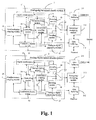
- Fig. 1 is a schematic diagram of an analog-digital mixed chaotic system according to an embodiment of the present invention
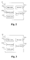
- Fig. 2 is a block diagram of one timing/counting module as shown in Fig. 1 according to an embodiment of present invention
- Fig. 3 is a block diagram of the other timing/counting module as shown in Fig. 1 according to an embodiment of present invention
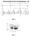
- Fig. 4 is a schematic view of a main timing for running the analog-digital mixed chaotic system shown in Fig. 1 ;
- Fig. 5 is a schematic view of a main timing for running the synchronization coupling module shown in Fig. 1 ;
- Fig. 6 is a schematic view of a main timing for running the disturbance coupling module shown in Fig. 1 ;
- Fig. 7 is a phase diagram of the digital chaotic system 1;
- Fig. 8 is a phase diagram of the continuous chaotic system 1;
- Fig. 9 is a schematic view showing errors between the state variables of the continuous Lorenz chaotic systems 1 and 2;
- Fig. 10 is a schematic view of the distribution of the 2,000,000 keys generated by the analog-digital mixed chaotic system.
- Fig. 1 shows a secure communication system according to an embodiment of the present invention, in which two analog-digital mixed chaotic systems 1 and 2 are separated from each other.
- the analog-digital mixed chaotic system 1 includes a digital chaotic system 11, a continuous chaotic system 12, a timing/counting module 13, a controlling module 14, a synchronization coupling module 15, a disturbance coupling module 16, an analog to digital (A/D) converting module 17, encoding modules 18 and 19, a multiplexing switch 110, data buffering modules 111 and 112, and a encrypting/decrypting module 113, and the like.
- the analog-digital mixed chaotic system 2 includes a digital chaotic system 21, a continuous chaotic system 22, a timing/counting module 23, a controlling module 24, a synchronization coupling module 25, a disturbance coupling module 26, an A/D converting module 27, encoding modules 28 and 29, a multiplexing switch 210, data buffering modules 211 and 212, and a encrypting/decrypting module 213, and the like.
- the digital chaotic systems 11 and 21 may be represented by a difference equation of a continuous chaotic system with finite precision, or a discrete chaotic system with other finite precision.
- the digital chaotic systems 11 and 21 generate an output every time after ⁇ ' 5 times of iterations are completed. It is assumed that T 1 and T 2 are the respective time required for the digital chaotic systems 11 and 21 to execute one iteration. For simplicity, given that T 1 ⁇ T 2 without losing universality, the transmitting and receiving parties may take T 2 as the time required for each of digital chaotic systems 11 and 21 to execute one iteration.
- the digital chaotic systems 11 and 21 can be completely synchronized.
- the operating states of the digital chaotic systems 11 and 21 may be classified into a running state (i.e. iterative computing state) and a holding state.
- the operating states of the continuous chaotic systems 12 and 22 may be classified into a running state and a holding state as well.
- the timing/counting modules 13 and 23 of Fig. 1 have the following functions:
- the timing/counting modules 13 and 23 may record the times of iterations of the digital chaotic systems 11 and 21, respectively.
- the counters C11 and C21 provide the respective local controlling modules 14 and 24 with control signals for controlling the output of the digital chaotic systems 11 and 21, respectively.
- the counters C12 and C22 provide the respective local controlling modules 14 and 24 with control signals for controlling the digital chaotic systems 11 and 21 to output state values to the synchronization coupling modules 15 and 25, respectively.
- the counters C13 and C23 provide the respective local controlling modules 14 and 24 with control signals for controlling the disturbance coupling modules 16 and 26 to disturb the digital chaotic systems 11 and 21, respectively.
- timing/counting modules 13 and 23 may record the durations for which the continuous chaotic systems 12 and 22 stay in the continuous running state (i.e. running time of the continuous chaotic system) respectively.
- timers T11, T12 and T21, T22 are provided in each of the timing/counting modules 13 and 23, i.e., timers T11, T12 and T21, T22.
- the timers T11 and T21 provide the respective local controlling modules 14 and 24 with control signals for controlling the synchronization coupling modules 15 and 25 to output synchronized impulses, respectively.
- the timers T12 and T22 provide the respective local controlling modules 14 and 24 with control signals for controlling the disturbance coupling modules 16 and 26 to sample the continuous chaotic systems.
- the timers may record the running time of the continuous chaotic system, that is, the timers in the timing/counting modules 13 and 23 suspend when the continuous chaotic systems stay in a holding state. Therefore, with regard to the running time, the duration for which the above-mentioned synchronizing impulse is applied to the continuous chaotic system is ⁇ 1 , and the period of the sampling control signal is ⁇ 2 .
- the controlling modules 14 and 24 of Fig. 1 have the following functions:
- controlling modules 14 and 24 may control respective local digital chaotic systems 11 and 21 to initiate each key generation process, and control respective local digital chaotic systems 11 and 21 to complete each key generation process, according to the states of the respective local data buffering modules 111, 112 or 211, 212 and the signals from the counters C11 and C21 in the timing/counting modules 13 and 23.
- controlling modules 14 and 24 may control the output of the respective local digital chaotic systems 11 and 21 to the respective local synchronization coupling modules 15 and 25, according to the signals from the counters C12 and C22 in the respective local timing/counting modules 13 and 23.
- controlling modules 14 and 24 may control the time at which the synchronization coupling modules 15 and 25 output the synchronizing impulse signals, according to the signals from the timers T11 and T21 in the respective local timing/counting modules 13 and 23, so that the continuous chaotic systems 12 and 22 may realize stable chaotic synchronization, without transmitting the synchronizing impulse signals.
- controlling modules 14 and 24 may control the time at which the disturbance coupling modules 16 and 26 sample the respective local continuous chaotic systems 12 and 22, according to the signals from the timers T11 and T21 in the respective local timing/counting modules 13 and 23.
- controlling modules 14 and 24 may control the time at which the disturbance coupling modules 16 and 26 output the disturbing signals, according to the signals from the counters C13 and C23 in the respective local timing/counting modules 13 and 23, so that the digital chaotic systems 11 and 21 can overcome the problem of characteristic degradation.
- controlling modules 14 and 24 may control the operating states of respective local digital chaotic systems 11 and 21 and the operating states of respective local continuous chaotic systems 12 and 22, according to the signals from all the counters and timers in the respective local timing/counting modules 13 and 23. Further, the controlling modules 14 and 24 may control data rate of the dataflow inputted into the data buffers, according to the states of respective local data buffers.
- the synchronization coupling modules 15 and 25 Under control of the controlling modules 14 and 24 of Fig. 1 , the synchronization coupling modules 15 and 25 generate synchronizing impulse signals, according to the state values inputted by the respective local digital chaotic systems and current state values of the respective local continuous chaotic systems, and control the respective local continuous chaotic systems 12 and 22 synchronously according to the synchronizing impulse signal, so that a stable chaotic synchronization may be achieved between the separated continuous chaotic systems 12 and 22 without transmitting the synchronizing impulse signals.
- the synchronization coupling modules 15 and 25 may be adapted to realize the synchronization between the separated continuous chaotic systems 12 and 22 according to the following mathematical model (3): ⁇ ⁇ X ⁇ j ⁇
- the disturbance coupling modules 16 and 26 respectively sample the states of the respective local continuous chaotic systems 12 and 22, and output the sampled states to the respective local digital chaotic systems 11 and 21 after a conversion of a disturbance coupling function, so as to prevent characteristic degradation of the digital chaotic systems 11 and 21, respectively.
- the disturbance coupling modules 16 and 26 may prevent characteristic degradation of the digital chaotic systems 11 and 12 according to the following mathematical model (4):
- the disturbance coupling function H( ⁇ ) is required to construct the disturbance coupling function H( ⁇ ) according to the characteristics of the continuous chaotic systems 12 and 22 and the characteristic degradation property of the digital chaotic systems 11 and 21. Further, it is required to determine the time t k (i.e. sampling clock period ⁇ 2 ) at which the continuous chaotic systems is to be sampled, and the times of iterations for disturbing the respective local digital chaotic systems, so that the statistical characteristic of the disturbance coupling function H( ⁇ ) may approach to a probability distribution that truncation error of a digital chaotic system follows, with probability 1 in a certain precision. Therefore, the characteristic degradation caused by the finite precision effect may be overcome in the digital chaotic systems affected by the disturbed signal.
- the A/D converting modules 17 and 27 of Fig. 1 convert the continuous chaotic signals generated by the respective local continuous chaotic systems 12 and 22 into digital chaotic sequences.
- the encoding modules 18, 19 and 28, 29 of Fig. 1 encode the respective local digital chaotic sequences.
- the multiplexing switches 110 and 210 of Fig. 1 select one of the following sequences: the digital chaotic sequences generated by from the digital chaotic systems 11 and 21, the continuous (analog) chaotic signals generated by the continuous chaotic systems 12 and 22, and the digital chaotic sequences obtained by A/D converting the output of the continuous chaotic systems 12 and 22, as the output of the analog-digital mixed chaotic system.
- the digital chaotic sequence generated by the system may be adapted to encode the data as either a pseudorandom number sequence or a key stream.
- the continuous (analog) chaotic signals generated by the system can be adapted to design a chaotic synchronization based secure communication system.
- the data buffering modules 111, 112 and 211, 212 of Fig. 1 are adapted to buffer the respective local plaintext and cipher text, respectively.
- the encrypting/decrypting modules 113 and 213 of Fig. 1 are adapted to encrypt/decrypt the data inputted into the respective local data buffers.
- the encrypting/decrypting modules may encrypt/decrypt digital signals by using the encoded digital chaotic sequences, or may realize chaotic synchronization based secure communication by using the continuous (analog) chaotic signals generated by the continuous chaotic systems.
- the controlling modules 14 and 24 control the respective local digital chaotic systems, the continuous chaotic systems, the synchronization coupling modules, the disturbance coupling module and the data buffers, according to the various clock signals and control signals provided by the timing/counting modules 13 and 23.
- signals I 1,1 , D 1,1 , D 1 , 2 , C 1,0 , C 1,1 , C 1,2 , C 1 , 3 , C 1 , 4 , C 1,5 , C 1 , 6 , C 1,7 , C 1,8 , C 1,9 respectively indicate the following meanings:
- I 1,1 indicates the input data stream, where each impulse indicates that one bit of data is inputted into the data buffering module 112 of the analog-digital mixed chaotic system 1.
- D 1,1 and D 1,2 indicate whether data in the two buffers B11 and B12 of the data buffering module 112 is ready, respectively. If data in a buffer is ready, a state flag of the buffer is set to "1", otherwise, the state flag of the buffer is set to "0". If a state flag of a buffer is "1", new data is prohibited to be inputted into this buffer, and if the state flag is "0", new data is allowed to be inputted into this buffer. Moreover, when data within the above buffer is encrypted/decrypted, the corresponding state flag will be set to "0".
- C 1,0 indicates the data of which buffers will be processed by the analog-digital mixed chaotic system 1.
- Data in the buffer B11 will be processed by the analog-digital mixed chaotic system 1 if C 1,0 is "1", and data in the buffer B12 will be processed if C 1,0 is " 0 " .
- C 1,1 indicates that the digital chaotic system 11 starts a process of generating one element of a chaotic sequence.
- C 1,2 indicates that the digital chaotic system 11 ends a process of generating one element of the chaotic sequence. If data in the buffer is not ready, the digital chaotic system 11 suspends the process of generating the next element of the chaotic sequence, and if data in the buffer is ready, the digital chaotic system 11 starts the process of generating the next element of the chaotic sequence automatically.
- Each impulse of C 1,4 corresponds to the completion of one iteration in the digital chaotic system 11.
- C 1,5 indicates that the digital chaotic system 11 outputs a state value to the synchronization coupling module 15 every time after times of iterations are completed.
- C 1,6 indicates the output of the synchronization coupling module 15.
- the duration for which the synchronization coupling module 15 output the synchronizing impulse is A 1 .
- C 1,8 indicates the control to the digital chaotic system 11.
- the digital chaotic system 11 executes times of iterations within two adjacent impulses.
- C 1,9 indicates that the disturbance coupling module 16 samples the continuous chaotic system 12.
- the period for the disturbance coupling module 16 to sample the continuous chaotic system 12 is ⁇ 2 , with respect to the definition of running time.
- the counter C11 When the timer C11 record that the digital chaotic system 11 has completed ⁇ ' 5 times of iterations, the counter C11 generates a completion signal (shown as C 1,2 in Fig. 4 ), and the counter C11 is reset. Under the trigger of the rising edge of the signal C 1,2 , the digital chaotic system 11 outputs a key for encryption.
- the analog-digital mixed chaotic system 1 processes the data in the buffer B11 with the encryption key generated by the digital chaotic system 11.
- a completion signal (shown as C 1,3 in Fig. 4 ) is generated, and the state signal D 1 of buffer B11 is set to 0. At this time, the buffer B11 enters a data preparation period.
- the analog-digital mixed chaotic system 1 processes the data in buffer B12. If the state signal D 2 (shown as D 2 in Fig. 2(a) ) of the buffer B12 is "1", the stalling signal restarts the digital chaotic system 11 when the counter C11 generates the completion signal, the counter C11 resumes counting, and thereby the digital chaotic system 11 enters a process of generating the next key, meanwhile the signal C 1,0 changes from "0" to "1".
- the timers T11, T12 and the counters C12, C13 continues timing and counting.
- the digital chaotic system 11 and the continuous chaotic system 12 stay in a holding state when the counter C11 generates a completion signal, and meanwhile, the timers T11, T12 and the counters C12, C13 stop timing and counting.
- the time required for the digital chaotic system 11 to complete an iterative computation is T 2 .
- the running time ⁇ 1 of the continuous chaotic system recorded by the timer T11 is just T 2 ⁇ (shown as segment I in Fig. 4 ).
- the digital chaotic system 11 outputs a state value to the synchronization coupling module 15 under control of the controlling module 14, the synchronization coupling module 15 outputs and applies a synchronizing impulse to the continuous chaotic system 12 under control of the controlling module 14, and the counter C12 and the timer T11 are reset.
- the time required for executing each iteration may be not T 2 . Therefore, when the counter C12 records that the digital chaotic system 11 has completed ⁇ ' 4 times of iterations, the running time ⁇ 1 of the continuous chaotic system 12 may be less than T 2 ⁇ ⁇ ' 4 (shown as segment II in Fig. 5 ), and thus the digital chaotic system 11 is required to stay in the holding state after the ⁇ ' 4 times of iterations, until the running time ⁇ 1 of the continuous chaotic system 12 arrives T 2 ⁇ ⁇ ' 4 .
- the synchronization coupling module 15 outputs and applies the synchronizing impulse to the continuous chaotic system 12, and then the counter C12 and the timer T11 are reset.
- the digital chaotic system 11 When the running time ⁇ 1 of the continuous chaotic system 12 arrives T 2 ⁇ ⁇ ' 4 , the digital chaotic system 11 has not completed the ⁇ ' 4 times of iterations (shown as segment III in Fig. 5 ). In this case, the continuous chaotic system 12 is required to stay in the holding state after the running time ⁇ 1 arrives T 2 ⁇ ⁇ ' 4 , until the digital chaotic system 11 completes the ⁇ ' 4 times of iterations.
- the digital chaotic system 11 When the digital chaotic system 11 has completed ⁇ ' 4 times of iterations, the continuous chaotic system 12 leaves the holding state, the synchronization coupling module 15 outputs and applies the synchronizing impulse to the continuous chaotic system 12 to synchronously control the continuous chaotic system, and then the counter C12 and the timer T11 are reset.
- the time required for executing one iteration is T 2 .
- the running time ⁇ 2 of the continuous chaotic system 12 recorded by the timer T12 is just T 2 : ⁇ ' 3 (shown as segment I in Fig. 6 ).
- the disturbance coupling module 15 samples the continuous chaotic system 12 (shown as C 1,9 in Fig. 6 ) and converts the sampled values, under control of the controlling module 14, and outputs a disturbing signal to the digital chaotic system 11 to disturb the digital chaotic system 11, and then the counter C13 and the timer T12 are reset.
- the disturbance coupling module 15 samples the continuous chaotic system 12 (shown as C 1,9 in Fig. 6 ) and converts the sampled values under control of the controlling module 14, and outputs a disturbing signal to the digital chaotic system 11 to disturb the digital chaotic system 11, and then the counter C13 and the timer T12 are reset.
- the running time ⁇ 2 of the continuous chaotic system 12 is less than T 2 ⁇ ⁇ ' 3 (shown as segment III in Fig. 6 ).
- the digital chaotic system 11 should stay in the holding state after completing ⁇ ' 3 times of iterations, until the running time ⁇ 2 of the continuous chaotic system 12 arrives T 2 ⁇ ⁇ ' 3 .
- the disturbance coupling module 15 samples the continuous chaotic system 12 (shown as C 1,9 in Fig. 6 ) and converts the sampled values under control of the controlling module 14, and outputs a disturbing signal to the digital chaotic system 11 to disturb the digital chaotic system 11, and then the counter C13 and the timer T12 are reset.
- a criterion for holding a stable synchronization between the continuous chaotic systems 12 and 22 is illustrated as below.
- ⁇ 1 ⁇ 4 ⁇ ⁇ T 2 and q + 2 ⁇ L ⁇ ⁇ 1 ⁇ - ln ⁇ ⁇ d ⁇ > 1 , d ⁇ 1 a stable chaotic synchronization may be achieved between the continuous chaotic systems 12 and 22 without transmission of the synchronizing impulse.
- the disturbance coupling modules 16 and 26 disturbs the respective local digital chaotic systems 11 and 21 every time after ⁇ ' 3 times of iterations are completed in the digital chaotic systems 11 and 21.
- the analog-digital mixed chaotic system is designed by using the Lorenz chaotic system
- the operation precision of the digital chaotic system is 19 bits, which 7 bits are adapted to indicate the integer component of a variable in the digital chaotic system, 11 bits are adapted to indicate the decimal component of the variable in the digital chaotic system, and the remaining 1 bit is adapted to indicate the sign of the variable in the digital chaotic system.
- Fig. 7 is a phase diagram of the digital chaotic system 11
- Fig. 8 is a phase diagram of the continuous Lorenz chaotic system 12, and both of them illustrate that the attractors of the analog-digital mixed chaotic system still have the same level complexity as those of the Lorenz chaotic system.
- Fig. 7 is a phase diagram of the digital chaotic system 11
- Fig. 8 is a phase diagram of the continuous Lorenz chaotic system 12, and both of them illustrate that the attractors of the analog-digital mixed chaotic system still have the same level complexity as those of the Lorenz chaotic system.
- the disturbance coupling modules 16 and 26 sample, quantize and convert the respective local continuous chaotic systems 12 and 22 under control of the controlling modules 14 and 24, and obtain the disturbance signal for disturbing the digital chaotic systems.
- the analog-digital mixed chaotic system begins to output a key.
- a key stream of the analog-digital mixed systems 1, 2 is obtained after a nonlinear conversion on the encoded sequence.
- a cipher text (or a plaintext) can be obtained by XOR of the key and a plaintext (or a cipher text).
- Table 1 Nonlinear conversion F( ⁇ ) ⁇ 0 1 2 3 4 5 6 7 8 9 10 11 12 13 14 15 F( ⁇ ) 169 133 214 211 84 29 172 37 93 67 24 30 81 252 202 99 ⁇ 16 17 18 19 20 21 22 23 24 25 26 27 28 29 30 31 F( ⁇ ) 40 68 32 157 224 226 200 23 165 143 3 123 187 19 210 238 ⁇ 32 33 34 35 36 37 38 39 40 41 42 43 44 45 46 47 F( ⁇ ) 112 140 63 168 50 221 246 116 236 149 11 87 92 91 189 1 ⁇ 48 49 50 51 52 53 54 55 56 57 58 59 60 61 62 63 F( ⁇ ) 36 28 115 152 16 204 242 217 44 231 114 131 155 209 134 201
- the analog-digital mixed chaotic system is designed by using the Chen chaotic system.
- the operation precision of the digital chaotic system is 19 bits, which 7 bits are adapted to indicate the integer component of a variable in the digital chaotic system, 11 bits are adapted to indicate the decimal component of the variable in the digital chaotic system, and the remaining 1 bit is adapted to indicate the sign of the variable value in the digital chaotic system.
- the two communication parties initiate the digital chaotic systems 11 and 21 by using the appointed initial conditions, and randomly generate the initial states of the continuous chaotic systems 12 and 22.
- the synchronization coupling modules 15 and 25 Under control of the controlling modules 14 and 24, the synchronization coupling modules 15 and 25 output the synchronizing impulse signals to be applied to the respective local continuous chaotic systems 12 and 22.
- the disturbance coupling modules 16 and 26 sample, quantize and convert the respective local continuous chaotic systems 12 and 22, and obtain the disturbance signal for disturbing the digital chaotic systems.
- a key stream generated by the analog-digital mixed systems 1, 2 is obtained after a nonlinear conversion on the encoded sequence.
- a cipher text (or a plaintext) can be obtained by XOR of the key and a plaintext (or a cipher text).
- the analog-digital mixed chaotic system is designed by using a one-dimensional Logistic chaotic system and a Chen chaotic system as the digital chaotic system and the continuous chaotic system respectively.
- the operation precision of the digital chaotic system is 19 bits, which 18 bits are adpated to indicate the decimal component of a variable in the digital chaotic system, and the remaining 1 bit is adpated to indicate the sign of the variable in the digital chaotic system.
- the transmitting and receiving parties have appointed the time required for the digital chaotic systems 11 and 21 to perform one iteration, the actual time that the digital chaotic systems 11 and 21 take to execute each operation will be a bit different.
- the respective local digital chaotic system and continuous chaotic system are controlled by the controlling modules 14 and 24 in the analog-digital mixed chaotic systems 1 and 2, so that a stable synchronization between the continuous chaotic systems that are separated with each other in location can be achieved and thereby the characteristic degradation may be overcome in the digital chaotic system.
- j 1,2 denotes the continuous Chen chaotic systems 12 and 22 respectively;
- the synchronization coupling modules 15 and 25 Under control of the controlling modules 14 and 24, the synchronization coupling modules 15 and 25 output the synchronizing impulse signals to be applied to the respective local continuous chaotic systems 12 and 22.
- the disturbance coupling modules 16 and 26 sample, quantize and convert the respective local continuous chaotic systems 12 and 22, and obtain the disturbance signal for disturbing the digital chaotic systems,
- the analog-digital mixed chaotic system begins to output a key.
- a cipher text (or a plaintext) can be obtained by XOR of the key and a plaintext (or a cipher text).
Landscapes
- Engineering & Computer Science (AREA)
- Computer Networks & Wireless Communication (AREA)
- Signal Processing (AREA)
- Computer Security & Cryptography (AREA)
- Complex Calculations (AREA)
- Compression, Expansion, Code Conversion, And Decoders (AREA)
- Measuring Volume Flow (AREA)
- Mobile Radio Communication Systems (AREA)
- Communication Control (AREA)
- Transmission Systems Not Characterized By The Medium Used For Transmission (AREA)
- Feedback Control In General (AREA)
- Analogue/Digital Conversion (AREA)
- Reduction Or Emphasis Of Bandwidth Of Signals (AREA)
Abstract
Description
- The present application claims priority of Chinese application No.
200510121497.3 - The present invention relates to cryptography technology in information security field, and more particularly, to a system and method for generating analog-digital mixed chaotic signals as well as an encryption communication method.
- With the development of computer, communication and network technology, the progress of global informationization is speeding up. Up to now, network information system has become an infrastructure for countries, industries, groups and enterprises under development. The communication security of the network information system has therefore become an important issue associated with the continuous and stable development of economy and the safety of a country.
- At present, chaos has been applied in the secure communication field. The so-called chaos refers to a complex external manifestation resulted from its internal randomicity. In other words, the chaos is a kind of non-random movements that appears to be random. The chaotic signals are characterized by ergodicity, wideband, noise like, sensitive to the initial conditions, rapidly attenuated self correlation and weak cross correlation, and the like. These characteristics provide numerous mechanisms and methods to achieve secure communication. The Chaotic Encryption System in the art includes digital chaotic system and continuous (or analog) chaotic system.
- The digital chaotic system is less affected by noise interference and device parameters, and thereby it is easy to run stably for a long time and may be duplicated accurately. However, because digital chaotic sequences are all generated on computers or other equipment with limited precision, any digital chaotic sequence generator may be classified into a finite automation. In this case, the generated digital chaotic sequence presents degraded characteristics, such as short period, strong correlation and small linear complexity; in other words, the dynamics characteristics of a real digital chaotic system are much different from those of ideal real-value chaotic system.
- Compared with the digital chaotic system, the continuous chaotic system (i.e. analog chaotic system) has a continuous state (for example, voltage, current etc.) space, which allows the generated chaotic sequences to have a good cryptology characteristic. However, due to the effects of the deviation of device parameters and the circuit noise, it is hard to achieve a stable synchronization between two continuous chaotic systems for a long time. This severely slows the progress of practical application of the chaotic synchronization based secure communication system.
- Various embodiments of the invention provide a system and method for generating analog-digital mixed chaotic signal as well as an encryption communication method thereof, in which the problem of characteristic degradation is not tended to occur in the digital chaotic system, and the continuous chaotic system is capable of runing stably and synchronously for a long time.
- One embodiment of the invention provides an analog-digital mixed chaotic system, including:
- a digital chaotic system adapted to generate a digital chaotic sequence;
- a continuous chaotic system adapted to generate a continuous chaotic signal;
- a synchronization coupling module adapted to generate and output a synchronizing impulse signal to the continuous chaotic system for controlling the continuous chaotic system, according to states of the digital chaotic system and the continuous chaotic system;
- a disturbance coupling module adapted to disturb the digital chaotic system according to the state of the continuous chaotic system; and
- a controlling module adapted to control the states of the digital chaotic system, the continuous chaotic system, the synchronization coupling module and the disturbance coupling module.
- Another embodiment of the invention provides a method for generating an analog-digital mixed chaotic signal, including:
- generating a digital chaotic sequence from a digital chaotic system;
- generating a continuous chaotic signal from a continuous chaotic system;
- generating a synchronizing impulse signal for controlling the continuous chaotic system according to states of the digital chaotic system and the continuous chaotic system, and outputting the synchronizing impulse signal to the continuous chaotic system; and
- disturbing the digital chaotic system according to the state of the continuous chaotic system.
- Yet another embodiment of the invention provides an encryption communication method. An analog-digital mixed chaotic system is included in both communication parties, and the analog-digital mixed chaotic systems at both transmitting and receiving parties have the same initial conditions and the same system parameters. The method includes:
- encrypting, at a analog-digital mixed chaotic system in a transmitting party, a plaintext to be transmitted by using a chaotic signal generated by itself, and outputting a resultant cipher text;
- decrypting, at a analog-digital mixed chaotic system in a receiving party, a received cipher text by using a chaotic signal generated by itself, and outputtinga resultant plaintext;
- generating and outputting to the continuous chaotic systems, synchronizing impulse signals for controlling respective local continuous chaotic systems, according to states of local digital chaotic systems and continuous chaotic systems, by the analog-digital mixed chaotic systems of the transmitting and the receiving parties, respectively; and
- disturbing the digital chaotic systems by the analog-digital mixed chaotic systems of the transmitting and receiving parties, according to states of respective local continuous chaotic systems.
- Embodiments of the invention utilize the complementarity, in terms of the cryptography characteristics and the implementation technology, between a digital chaotic system and a chaotic synchronization based secure communication system. In these embodiments, the digital chaotic systems, which are separated from each other in location, control their own local continuous chaotic systems respectively, so that both of the separated continuous chaotic systems may run in a stable and synchronous state for a long time without transmitting synchronizing signals. This effectively enhances anti-attack ability of a chaotic system. Also in these embodiments, the continuous chaotic systems in turn disturb the respective local digital chaotic system to prevent the digital chaotic systems from characteristic degradation. Therefore, in the analog-digital mixed chaotic system, the shortcomings that the continuous chaotic systems cannot run in a stable and synchronous state for a long time and thereby the synchronizing signals need to be transmitted through a channel can be overcome, and meanwhile, the problem, i.e. the characteristic degradation of digital chaotic systems can be avoided.
- The present invention will be further described in conjunction with the figures and embodiments as follows, in which:
-
Fig. 1 is a schematic diagram of an analog-digital mixed chaotic system according to an embodiment of the present invention; -
Fig. 2 is a block diagram of one timing/counting module as shown inFig. 1 according to an embodiment of present invention; -
Fig. 3 is a block diagram of the other timing/counting module as shown inFig. 1 according to an embodiment of present invention; -
Fig. 4 is a schematic view of a main timing for running the analog-digital mixed chaotic system shown inFig. 1 ; -
Fig. 5 is a schematic view of a main timing for running the synchronization coupling module shown inFig. 1 ; -
Fig. 6 is a schematic view of a main timing for running the disturbance coupling module shown inFig. 1 ; -
Fig. 7 is a phase diagram of the digitalchaotic system 1; -
Fig. 8 is a phase diagram of the continuouschaotic system 1; -
Fig. 9 is a schematic view showing errors between the state variables of the continuous Lorenzchaotic systems -
Fig. 10 is a schematic view of the distribution of the 2,000,000 keys generated by the analog-digital mixed chaotic system. -
Fig. 1 shows a secure communication system according to an embodiment of the present invention, in which two analog-digital mixedchaotic systems - The analog-digital mixed
chaotic system 1 includes a digitalchaotic system 11, a continuouschaotic system 12, a timing/counting module 13, a controllingmodule 14, asynchronization coupling module 15, adisturbance coupling module 16, an analog to digital (A/D)converting module 17,encoding modules multiplexing switch 110,data buffering modules 111 and 112, and a encrypting/decrypting module 113, and the like. - The analog-digital mixed
chaotic system 2 includes a digitalchaotic system 21, a continuouschaotic system 22, a timing/counting module 23, a controllingmodule 24, asynchronization coupling module 25, adisturbance coupling module 26, an A/D converting module 27,encoding modules multiplexing switch 210,data buffering modules decrypting module 213, and the like. - Here, the digital
chaotic systems chaotic systems 
where, j=1, 2 denotes the digitalchaotic systems - X j (i) denotes a m-dimensional state variable of the digital chaotic system, in which X1(0) and X2(0) represent the initial conditions of the digital
chaotic systems - The digital
chaotic systems chaotic systems chaotic systems - Since the initial conditions and system parameters of the digital
chaotic systems chaotic systems chaotic systems chaotic systems chaotic systems - The dynamics characteristics of the continuous
chaotic systems 
where, j=1,2 denotes the continuouschaotic systems - X̃ j (t) is a n-dimensional state variable of the continuous chaotic system, in which X̃ 1 (0) and X̃ 2(0) are initial conditions of the continuous
chaotic systems - A is a constant matrix of order n, and
- Φ:Rn →Rn is a function for describing the nonlinear component of the continuous chaotic system.
- Also, in order to ensure that the continuous
chaotic systems chaotic systems chaotic systems - The timing/
counting modules Fig. 1 have the following functions: - Firstly, the timing/
counting modules chaotic systems - By reference to
Figs. 2 and 3 , three counters are provided in each of the timing/counting modules controlling modules chaotic systems controlling modules chaotic systems synchronization coupling modules controlling modules disturbance coupling modules chaotic systems - Secondly, the timing/
counting modules chaotic systems - By reference to
Figs. 2 and 3 , two timers are provided in each of the timing/counting modules controlling modules synchronization coupling modules controlling modules disturbance coupling modules counting modules - The controlling
modules Fig. 1 have the following functions: - Firstly, the controlling
modules chaotic systems chaotic systems data buffering modules counting modules - Secondly, the controlling
modules chaotic systems synchronization coupling modules counting modules - Thirdly, the controlling
modules synchronization coupling modules counting modules chaotic systems - Fourthly, the controlling
modules disturbance coupling modules chaotic systems counting modules - Fifthly, the controlling
modules disturbance coupling modules counting modules chaotic systems - It can be seen from the above, the controlling
modules chaotic systems chaotic systems counting modules modules - Under control of the controlling
modules Fig. 1 , thesynchronization coupling modules chaotic systems chaotic systems - The
synchronization coupling modules chaotic systems 
where, j=1,2 denotes thesynchronization coupling modules - B is a diagonal matrix of order n;
- tk denotes the time at which the
synchronization coupling modules - x̃ j (tk ) denotes state values of the continuous
chaotic systems - nk denotes the times of iterations when the digital
chaotic systems synchronization coupling modules - X j (nk ) denotes state values of the digital
chaotic systems - C(·) is a function for converting binary state values of the digital
chaotic systems - W(·) is function for mapping an independent variable from an m-dimension space to a n-dimension space.
- At the transmitting and receiving parties, it is required to construct, according to a criterion for keeping stable synchronization between the continuous
chaotic systems synchronization coupling modules chaotic systems - Under control of the controlling
modules Fig. 1 , thedisturbance coupling modules chaotic systems chaotic systems chaotic systems - The
disturbance coupling modules chaotic systems 
where, j=1,2 denotes thedisturbance coupling modules - X̃ j (τk ) (j=1,2) indicates state value of each the continuous
chaotic systems chaotic systems disturbance coupling modules - D(·) is a function for converting a decimal sample value into a binary sample value with finite precision,
- K is a predetermine positive integer, and
- indicates a predetermined number of times of iterations, and
- H(·) is a disturbance coupling function, which disturbs the digital chaotic systems every time that Δ'3 times of iterations are completed in the digital
chaotic systems - At the transmitting and receiving parties, it is required to construct the disturbance coupling function H(·) according to the characteristics of the continuous
chaotic systems chaotic systems probability 1 in a certain precision. Therefore, the characteristic degradation caused by the finite precision effect may be overcome in the digital chaotic systems affected by the disturbed signal. - The A/
D converting modules Fig. 1 convert the continuous chaotic signals generated by the respective local continuouschaotic systems - The
encoding modules Fig. 1 encode the respective local digital chaotic sequences. - The multiplexing switches 110 and 210 of
Fig. 1 select one of the following sequences: the digital chaotic sequences generated by from the digitalchaotic systems chaotic systems chaotic systems - The
data buffering modules Fig. 1 are adapted to buffer the respective local plaintext and cipher text, respectively. - The encrypting/decrypting
modules Fig. 1 are adapted to encrypt/decrypt the data inputted into the respective local data buffers. The encrypting/decrypting modules may encrypt/decrypt digital signals by using the encoded digital chaotic sequences, or may realize chaotic synchronization based secure communication by using the continuous (analog) chaotic signals generated by the continuous chaotic systems. - In the analog-digital mixed
chaotic systems modules counting modules - Next, the main timing for running the analog-digital mixed
chaotic system 1 will be illustrated by taking an example in which thesystem 1 encrypts a data signal. - In
Fig. 4, 5 and6 , signals I1,1, D1,1, D1,2, C1,0, C1,1, C1,2, C1,3, C1,4, C1,5, C1,6, C1,7, C1,8, C1,9 respectively indicate the following meanings: - (1) I1,1 indicates the input data stream, where each impulse indicates that one bit of data is inputted into the
data buffering module 112 of the analog-digital mixedchaotic system 1. - (2) D1,1 and D1,2 indicate whether data in the two buffers B11 and B12 of the
data buffering module 112 is ready, respectively. If data in a buffer is ready, a state flag of the buffer is set to "1", otherwise, the state flag of the buffer is set to "0". If a state flag of a buffer is "1", new data is prohibited to be inputted into this buffer, and if the state flag is "0", new data is allowed to be inputted into this buffer. Moreover, when data within the above buffer is encrypted/decrypted, the corresponding state flag will be set to "0". - (3) C1,0 indicates the data of which buffers will be processed by the analog-digital mixed
chaotic system 1. Data in the buffer B11 will be processed by the analog-digital mixedchaotic system 1 if C1,0 is "1", and data in the buffer B12 will be processed if C1,0 is "0" . - (4) C1,1 indicates that the digital
chaotic system 11 starts a process of generating one element of a chaotic sequence. - (5) C1,2 indicates that the digital
chaotic system 11 ends a process of generating one element of the chaotic sequence. If data in the buffer is not ready, the digitalchaotic system 11 suspends the process of generating the next element of the chaotic sequence, and if data in the buffer is ready, the digitalchaotic system 11 starts the process of generating the next element of the chaotic sequence automatically. - (6) C1,3 indicates that all of the data in the buffer has been processed.
- (7) Each impulse of C1,4 corresponds to the completion of one iteration in the digital
chaotic system 11. - (8) C1,5 indicates that the digital
chaotic system 11 outputs a state value to thesynchronization coupling module 15 every time after times of iterations are completed. - (9) C1,6 indicates the output of the
synchronization coupling module 15. With respect to the definition of running time, the duration for which thesynchronization coupling module 15 output the synchronizing impulse is A1. - (10) C1,7 indicates the output of the continuous
chaotic system 12. - (11) C1,8 indicates the control to the digital
chaotic system 11. The digitalchaotic system 11 executes times of iterations within two adjacent impulses. - (12) C1,9 indicates that the
disturbance coupling module 16 samples the continuouschaotic system 12. The period for thedisturbance coupling module 16 to sample the continuouschaotic system 12 is Δ2, with respect to the definition of running time. - The running timing of the analog-digital mixed
chaotic system 1 is shown as follows: - In
Fig. 4 , when signal C1,0 is "1", the analog-digital mixedchaotic system 1 processes the data in buffer B11. The input data I1,1 continually arrive at the analog-digital mixedchaotic system 1. When the data in the buffer B11 are ready, the state signal D1 changes from "0" to "1". At the rising edge of the state signal D1, the starting signal C1,1 of the digitalchaotic system 11 is generated, and thereby the digitalchaotic system 11 starts to execute iteration with the signal C1,0 changing from "1" to "0". Under the trigger of the rising edge of the state signal D1 the timers T11, T12 and the counters C11, C12, C13 in the timing/counting module 13 begin timing and counting. When the timer C11 record that the digitalchaotic system 11 has completed Δ'5 times of iterations, the counter C11 generates a completion signal (shown as C1,2 inFig. 4 ), and the counter C11 is reset. Under the trigger of the rising edge of the signal C1,2, the digitalchaotic system 11 outputs a key for encryption. The analog-digital mixedchaotic system 1 processes the data in the buffer B11 with the encryption key generated by the digitalchaotic system 11. When all of the data in the buffer B11 has been processed, a completion signal (shown as C1,3 inFig. 4 ) is generated, and the state signal D1 of buffer B11 is set to 0. At this time, the buffer B11 enters a data preparation period. - When signal C1,0 is "0", the analog-digital mixed
chaotic system 1 processes the data in buffer B12. If the state signal D2 (shown as D2 inFig. 2(a) ) of the buffer B12 is "1", the stalling signal restarts the digitalchaotic system 11 when the counter C11 generates the completion signal, the counter C11 resumes counting, and thereby the digitalchaotic system 11 enters a process of generating the next key, meanwhile the signal C1,0 changes from "0" to "1". The timers T11, T12 and the counters C12, C13 continues timing and counting. If the state signal D2 of the buffer B12 is "0", the digitalchaotic system 11 and the continuouschaotic system 12 stay in a holding state when the counter C11 generates a completion signal, and meanwhile, the timers T11, T12 and the counters C12, C13 stop timing and counting. - In
Fig. 5 , it is assumed that, in normal conditions, the time required for the digitalchaotic system 11 to complete an iterative computation is T 2 . In this case, when the counter C12 records that the digitalchaotic system 11 has completed Δ'4 times of iterations, the running time Δ1 of the continuous chaotic system recorded by the timer T11 is just T 2· (shown as segment I inFig. 4 ). At this time, the digitalchaotic system 11 outputs a state value to thesynchronization coupling module 15 under control of the controllingmodule 14, thesynchronization coupling module 15 outputs and applies a synchronizing impulse to the continuouschaotic system 12 under control of the controllingmodule 14, and the counter C12 and the timer T11 are reset. - In actual situation, because of the effect of outer conditions such as running environment on the digital
chaotic system 11, the time required for executing each iteration may be not T2. Therefore, when the counter C12 records that the digitalchaotic system 11 has completed Δ'4 times of iterations, the running time Δ1 of the continuouschaotic system 12 may be less than T2·Δ'4 (shown as segment II inFig. 5 ), and thus the digitalchaotic system 11 is required to stay in the holding state after the Δ'4 times of iterations, until the running time Δ1 of the continuouschaotic system 12 arrives T 2 · Δ'4 . Once the running time Δ1 of the continuouschaotic system 12 arrives T 2 · Δ'4, the digitalchaotic system 11 leaves the holding state, thesynchronization coupling module 15 outputs and applies the synchronizing impulse to the continuouschaotic system 12, and then the counter C12 and the timer T11 are reset. - When the running time Δ1 of the continuous
chaotic system 12 arrives T 2· Δ'4, the digitalchaotic system 11 has not completed the Δ'4 times of iterations (shown as segment III inFig. 5 ). In this case, the continuouschaotic system 12 is required to stay in the holding state after the running time Δ1 arrives T2 · Δ'4, until the digitalchaotic system 11 completes the Δ'4 times of iterations. When the digitalchaotic system 11 has completed Δ'4 times of iterations, the continuouschaotic system 12 leaves the holding state, thesynchronization coupling module 15 outputs and applies the synchronizing impulse to the continuouschaotic system 12 to synchronously control the continuous chaotic system, and then the counter C12 and the timer T11 are reset. - In
Fig. 6 , it is assumed that, in normal conditions, the time required for executing one iteration is T 2. When thecounter C 13 records that the digitalchaotic system 11 has completed Δ'3 times of iterations, the running time Δ2 of the continuouschaotic system 12 recorded by the timer T12 is just T 2 : Δ'3 (shown as segment I inFig. 6 ). At this time, thedisturbance coupling module 15 samples the continuous chaotic system 12 (shown as C1,9 inFig. 6 ) and converts the sampled values, under control of the controllingmodule 14, and outputs a disturbing signal to the digitalchaotic system 11 to disturb the digitalchaotic system 11, and then the counter C13 and the timer T12 are reset. - In actual situation, because of the effect of outer conditions such as running environment on the digital
chaotic system 11, the time required for executing each iteration may be not T2 . Therefore, when the running time Δ2 of the continuouschaotic system 12 arrives T 2 · Δ'3, the digitalchaotic system 11 has not completed Δ'3 times of iterations (shown as segment II inFig. 6 ). In this case, continuouschaotic system 12 should stay in the holding state after the running time Δ2 arrives T 2 · Δ'3, until the digitalchaotic system 11 completed Δ'3 times of iterations. When the digitalchaotic system 11 has completed Δ'3 times of iterations, the continuouschaotic system 12 leaves the holding state, thedisturbance coupling module 15 samples the continuous chaotic system 12 (shown as C1,9 inFig. 6 ) and converts the sampled values under control of the controllingmodule 14, and outputs a disturbing signal to the digitalchaotic system 11 to disturb the digitalchaotic system 11, and then the counter C13 and the timer T12 are reset. - When the counter C13 records that the digital
chaotic system 11 has completed Δ'3 times of iterations, the running time Δ2 of the continuouschaotic system 12 is less than T 2 · Δ'3 (shown as segment III inFig. 6 ). In this case, the digitalchaotic system 11 should stay in the holding state after completing Δ'3 times of iterations, until the running time Δ2 of the continuouschaotic system 12 arrives T 2· Δ'3. When the running time Δ2 of the continuouschaotic system 12 arrives T 2 · Δ'3, the digitalchaotic system 11 leaves the holding state, thedisturbance coupling module 15 samples the continuous chaotic system 12 (shown as C1,9 inFig. 6 ) and converts the sampled values under control of the controllingmodule 14, and outputs a disturbing signal to the digitalchaotic system 11 to disturb the digitalchaotic system 11, and then the counter C13 and the timer T12 are reset. - A criterion for holding a stable synchronization between the continuous
chaotic systems - (1) Given that B is a diagonal matrix of order n, I is an identity matrix of order n, d is the largest Eigenvalue of matrix (I+B) T·(I+B), q is the largest Eigenvalue of (A+A T ), and L is a local Lipschitz constant of the nonlinear mapping Φ in equation (2). The digital
chaotic systems synchronization coupling modules synchronization coupling modules 

chaotic systems - (2) The
disturbance coupling modules chaotic systems chaotic systems 
- (3) If the digital chaotic system is a difference equation of a continuous chaotic system with finite word length, which is identical to the equation (2), the digital chaotic system may be expressed as equation (7)

where, τ is a positive real number. - λ1 is assumed to be the largest Eigenvalue of (I+τ·A)T(I+τ·A).
- It should be noted that all the time in the above criterions is present by taking the running time of the continuous chaotic system as a reference time.
- In this embodiment, the analog-digital mixed chaotic system is designed by using the Lorenz chaotic system, The operation precision of the digital chaotic system is 19 bits, which 7 bits are adapted to indicate the integer component of a variable in the digital chaotic system, 11 bits are adapted to indicate the decimal component of the variable in the digital chaotic system, and the remaining 1 bit is adapted to indicate the sign of the variable in the digital chaotic system.
- It is assumed that the digital Lorenz
chaotic systems 
where, j=1,2 denotes the digitalchaotic systems - the parameters are σ = 10, r = 28, β = 2.5, τ = 5×10⁻⁴s;
- h(i,·) is the disturbance coupling function, and

- It is assumed that the continuous Lorenz
chaotic systems 
where, j=1,2 denotes the continuous Lorenzchaotic systems - the parameters are σ = 10, r = 28, β = 2.66, b1 = -0.2, b2 = -0.6, b3 = -0.6;
- Lipschiz index L of the continuous Lorenz chaotic system is about 50.
- The workflow of the analog-digital mixed chaotic cipher system is shown as follows.
- (1) Two communication parties appoint the following parameters according to equation (9) for the digital chaotic system, equation (11) for the continuous chaotic system and equations (5), (6a), (6b), (8a) and (8b) for the synchronization conditions:
- the time T2 =0.35ms for the digital
chaotic systems - the period Δ'4 =10 for the digital
chaotic systems synchronization coupling modules - the duration Δ1=3.5ms for which the
synchronization coupling modules - the period Δ'3 =1000 for the
disturbance coupling modules chaotic systems - the predetermined constant K=1000 for the disturbance coupling modules, and
- the period Δ2=0.35s for the
disturbance coupling modules chaotic systems - (2) The two communication parties further appoint that:
- the initial conditions of the digital
chaotic systems - the times of iterations when the digital chaotic systems output the encryption/decryption key is Δ'5 = 1, and
- the output signal selected by the multiplexing switch is the digital chaotic sequence generated by the digital
chaotic systems - (3) The digital
chaotic systems chaotic systems - (4) Under control of the controlling
modules synchronization coupling modules chaotic systems Fig. 7 is a phase diagram of the digitalchaotic system 11,Fig. 8 is a phase diagram of the continuous Lorenzchaotic system 12, and both of them illustrate that the attractors of the analog-digital mixed chaotic system still have the same level complexity as those of the Lorenz chaotic system.Fig. 9 shows the errors between the state variables of the continuous Lorenzchaotic systems Fig. 9 that errors between the state variables of the two continuous chaotic systems converge to zero, that is, the continuouschaotic system 1 and the continuouschaotic system 2 are synchronized. - (5) The
disturbance coupling modules chaotic systems modules - (6) After the digital chaotic system has completed 1000 times of initial iterations, the analog-digital mixed chaotic system begins to output a key. A digital chaotic sequence generated by the digital
chaotic systems encoding modules mixed systems Fig. 10 is the statistical distribution diagram for the 2,000,000 keys k 1(i) (i=0,1,2,...,2,000,000) generated by the analog-digital mixedchaotic system 1. As shown inFig. 10 , it is illustrated that the distribution of the key sequences generated by an analog-digital mixed chaotic system is relatively uniform. At last, a cipher text (or a plaintext) can be obtained by XOR of the key and a plaintext (or a cipher text).Table 1 Nonlinear conversion F(·) ν 0 1 2 3 4 5 6 7 8 9 10 11 12 13 14 15 F(ν) 169 133 214 211 84 29 172 37 93 67 24 30 81 252 202 99 ν 16 17 18 19 20 21 22 23 24 25 26 27 28 29 30 31 F(ν) 40 68 32 157 224 226 200 23 165 143 3 123 187 19 210 238 ν 32 33 34 35 36 37 38 39 40 41 42 43 44 45 46 47 F(ν) 112 140 63 168 50 221 246 116 236 149 11 87 92 91 189 1 ν 48 49 50 51 52 53 54 55 56 57 58 59 60 61 62 63 F(ν) 36 28 115 152 16 204 242 217 44 231 114 131 155 209 134 201 ν 64 65 66 67 68 69 70 71 72 73 74 75 76 77 78 79 F(ν) 96 80 163 235 215 182 158 79 183 90 198 120 166 18 175 213 ν 80 81 82 83 84 85 86 87 88 89 90 91 92 93 94 95 F(ν) 97 195 180 65 82 125 141 8 31 153 0 25 4 83 247 225 ν 96 97 98 99 100 101 102 103 104 105 106 107 108 109 110 111 F(ν) 253 118 47 39 176 139 14 171 162 110 147 77 105 124 9 10 ν 112 113 114 115 116 117 118 119 120 121 122 123 124 125 126 127 F(ν) 191 239 243 197 135 20 254 100 222 46 75 26 6 33 107 102 ν 128 129 130 131 132 133 134 135 136 137 138 139 140 141 142 143 F(ν) 2 245 146 138 12 179 126 208 122 71 150 229 38 128 173 223 ν 144 145 146 147 148 149 150 151 152 153 154 155 156 157 158 159 F(ν) 161 48 55 174 54 21 34 56 244 167 69 76 129 233 132 151 ν 160 161 162 163 164 165 166 167 168 169 170 171 172 173 174 175 F(ν) 53 203 206 60 113 17 199 137 117 251 218 248 148 89 130 196 ν 176 177 178 179 180 181 182 183 184 185 186 187 188 189 190 191 F(ν) 255 73 57 103 192 207 13 184 15 142 66 35 145 108 219 164 ν 192 193 194 195 196 197 198 199 200 201 202 203 204 205 206 207 F(ν) 52 241 72 194 111 61 45 64 190 62 188 193 170 186 78 85 ν 208 209 210 211 212 213 214 215 216 217 218 219 220 221 222 223 F(ν) 59 220 104 127 156 216 74 86 119 160 237 70 181 43 101 250 ν 224 225 226 227 228 229 230 231 232 233 234 235 236 237 238 239 F(ν) 227 185 177 159 94 249 230 178 49 234 109 95 228 240 205 136 ν 240 241 242 243 244 245 246 247 248 249 250 251 252 253 254 255 F(ν) 22 58 88 212 98 41 7 51 232 27 5 121 144 106 42 154 - In this embodiment, the analog-digital mixed chaotic system is designed by using the Chen chaotic system. The operation precision of the digital chaotic system is 19 bits, which 7 bits are adapted to indicate the integer component of a variable in the digital chaotic system, 11 bits are adapted to indicate the decimal component of the variable in the digital chaotic system, and the remaining 1 bit is adapted to indicate the sign of the variable value in the digital chaotic system.
- It is assumed that the digital Chen
chaotic systems 
where, j=1,2 denotes the digitalchaotic systems - the parameters are a=3 5, b=3, c=28, τ=5×10⁻⁴s;
- h(i,·) is a disturbance coupling function, and

- where D(●) is an A/D conversion function, and In this embodiment, the output of the continuous chaotic system is converted into a digital amount of 19 bits;
- the disturbance coupling intensities are η1=0,01, η2=0.01, η3=0.01.
- It is assumed that the continuous Chen
chaotic systems 
where, j=1,2 denotes the continuous Chenchaotic systems - the parameters are a = 35, b = 3, c = 28, b 1 = -0.8, b 2 = -0.8, b 3 = -0.8;
- Lipschiz index L of the Chen system is about 85.
- The workflow of the analog-digital mixed chaotic cipher system is as follows.
- (1) Two communication parties appoint the following parameters according to equation (9) for the digital chaotic system, equation (11) for the continuous chaotic system and equations (5), (6a), (6b), (8a) and (8b) for the synchronization conditions:
- the time T2 =0.33ms for the digital
chaotic systems - the period Δ'4=30 for the digital
chaotic systems synchronization coupling modules - the duration Δ1=10ms of the
synchronization coupling modules - the period Δ'3 =1000 for the
disturbance coupling modules chaotic systems - the predetermined constant K=3000 for the disturbance coupling modules, and
- the period Δ2=0.33s for the
disturbance coupling modules chaotic systems - (2) The two communication parties appoint further that:
- the initial conditions of the digital
chaotic systems - the times of iterations when the digital chaotic systems to output the encryption/decryption key is Δ'5=1, and
- the output signal selected by the multiplexing switch is the digital chaotic sequence generated by the digital
chaotic systems - (3) The two communication parties initiate the digital
chaotic systems chaotic systems - (4) Under control of the controlling
modules synchronization coupling modules chaotic systems - (5) Also under control of the controlling
modules disturbance coupling modules chaotic systems - (6) The digital chaotic sequence generated by the digital
chaotic systems encoding modules mixed systems Table 2(a) Nonlinear conversion F0(·) ν 0 1 2 3 4 5 6 7 8 9 10 11 12 13 14 15 F(ν) 169 133 214 211 84 29 172 37 93 67 24 30 81 252 202 99 ν 16 17 18 19 20 21 22 23 24 25 26 27 28 29 30 31 F(ν) 40 68 32 157 224 226 200 23 165 143 3 123 187 19 210 238 ν 32 33 34 35 36 37 38 39 40 41 42 43 44 45 46 47 F(ν) 112 140 63 168 50 221 246 116 236 149 11 87 92 91 189 1 ν 48 49 50 51 52 53 54 55 56 57 58 59 60 61 62 63 F(ν) 36 28 115 152 16 204 242 217 44 231 114 131 155 209 134 201 ν 64 65 66 67 68 69 70 71 72 73 74 75 76 77 78 79 F(ν) 96 80 163 235 215 182 158 79 183 90 198 120 166 18 175 213 ν 80 81 82 83 84 85 86 87 88 89 90 91 92 93 94 95 F(ν) 97 195 180 65 82 125 141 8 31 153 0 25 4 83 247 225 ν 96 97 98 99 100 101 102 103 104 105 106 107 108 109 110 111 F(ν) 253 118 47 39 176 139 14 171 162 110 147 77 105 124 9 10 ν 112 113 114 115 116 117 118 119 120 121 122 123 124 125 126 127 F(ν) 191 239 243 197 135 20 254 100 222 46 75 26 6 33 107 102 ν 128 129 130 131 132 133 134 135 136 137 138 139 140 141 142 143 F(ν) 2 245 146 138 12 179 126 208 122 71 150 229 38 128 173 223 ν 144 145 146 147 148 149 150 151 152 153 154 155 156 157 158 159 F(ν) 161 48 55 174 54 21 34 56 244 167 69 76 129 233 132 151 ν 160 161 162 163 164 165 166 167 168 169 170 171 172 173 174 175 F(ν) 53 203 206 60 113 17 199 137 117 251 218 248 148 89 130 196 ν 176 177 178 179 180 181 182 183 184 185 186 187 188 189 190 191 F(ν) 255 73 57 103 192 207 13 184 15 142 66 35 145 108 219 164 ν 192 193 194 195 196 197 198 199 200 201 202 203 204 205 206 207 F(ν) 52 241 72 194 111 61 45 64 190 62 188 193 170 186 78 85 ν 208 209 210 211 212 213 214 215 216 217 218 219 220 221 222 223 F(ν) 59 220 104 127 156 216 74 86 119 160 237 70 181 43 101 250 ν 224 225 226 227 228 229 230 231 232 233 234 235 236 237 238 239 F(ν) 227 185 177 159 94 249 230 178 49 234 109 95 228 240 205 136 ν 240 241 242 243 244 245 246 247 248 249 250 251 252 253 254 255 F(ν) 22 58 88 212 98 41 7 51 232 27 5 121 144 106 42 154 Table 2(b) Nonlinear conversion F1(·) ν 0 1 2 3 4 5 6 7 8 9 10 11 12 13 14 15 F(ν) 56 232 45 166 207 222 179 184 175 96 85 199 68 111 107 91 ν 16 17 18 19 20 21 22 23 24 25 26 27 28 29 30 31 F(ν) 195 98 51 181 41 160 226 167 211 145 17 6 28 188 54 75 ν 32 33 34 35 36 37 38 39 40 41 42 43 44 45 46 47 F(ν) 239 136 108 168 23 196 22 244 194 69 225 214 63 61 142 152 ν 48 49 50 51 52 53 54 55 56 57 58 59 60 61 62 63 F(ν) 40 78 246 62 165 249 13 223 216 43 102 122 39 47 241 114 ν 64 65 66 67 68 69 70 71 72 73 74 75 76 77 78 79 F(ν) 66 212 65 192 115 103 172 139 247 173 128 31 202 44 170 52 ν 80 81 82 83 84 85 86 87 88 89 90 91 92 93 94 95 F(ν) 210 11 238 233 93 148 24 248 87 174 8 197 19 205 134 185 ν 96 97 98 99 100 101 102 103 104 105 106 107 108 109 110 111 F(ν) 255 125 193 49 245 138 106 177 209 32 215 2 34 4 104 113 ν 112 113 114 115 116 117 118 119 120 121 122 123 124 125 126 127 F(ν) 7 219 157 153 97 190 230 89 221 81 144 220 154 163 171 208 ν 128 129 130 131 132 133 134 135 136 137 138 139 140 141 142 143 F(ν) 129 15 71 26 227 236 141 191 150 123 92 162 161 99 35 77 ν 144 145 146 147 148 149 150 151 152 153 154 155 156 157 158 159 F(ν) 200 158 156 58 12 46 186 110 159 90 242 146 243 73 120 204 ν 160 161 162 163 164 165 166 167 168 169 170 171 172 173 174 175 F(ν) 21 251 112 117 127 53 16 3 100 109 198 116 213 180 234 9 ν 176 177 178 179 180 181 182 183 184 185 186 187 188 189 190 191 F(ν) 118 25 254 64 18 224 189 5 250 1 240 42 94 169 86 67 ν 192 193 194 195 196 197 198 199 200 201 202 203 204 205 206 207 F(ν) 133 20 137 155 176 229 72 121 151 252 30 130 33 140 27 95 ν 208 209 210 211 212 213 214 215 216 217 218 219 220 221 222 223 F(ν) 119 84 178 29 37 79 0 70 237 88 82 235 126 218 201 253 ν 224 225 226 227 228 229 230 231 232 233 234 235 236 237 238 239 F(ν) 48 149 101 60 182 228 187 124 14 80 57 38 50 132 105 147 ν 240 241 242 243 244 245 246 247 248 249 250 251 252 253 254 255 F(ν) 55 231 36 164 203 83 10 135 217 76 131 143 206 59 74 183 Table 2(c) Nonlinear conversion F2(•) ν 0 1 2 3 4 5 6 7 8 9 10 11 12 13 14 15 F(ν) 99 124 119 123 242 107 111 197 48 1 103 43 254 215 171 118 ν 16 17 18 19 20 21 22 23 24 25 26 27 28 29 30 31 F(ν) 202 130 201 125 250 89 71 240 173 212 162 175 156 164 114 192 ν 32 33 34 35 36 37 38 39 40 41 42 43 44 45 46 47 F(ν) 183 253 147 38 54 63 247 204 52 165 229 241 113 216 49 21 ν 48 49 50 51 52 53 54 55 56 57 58 59 60 61 62 63 F(ν) 4 199 35 195 24 150 5 154 7 18 128 226 235 39 178 117 ν 64 65 66 67 68 69 70 71 72 73 74 75 76 77 78 79 F(ν) 9 131 44 26 27 110 90 160 82 59 214 179 41 227 47 132 ν 80 81 82 83 84 85 86 87 88 89 90 91 92 93 94 95 F(ν) 83 209 0 237 32 252 177 91 106 203 190 57 74 76 88 207 ν 96 97 98 99 100 101 102 103 104 105 106 107 108 109 110 111 F(ν) 208 239 170 251 67 77 51 133 69 249 2 127 80 60 159 168 ν 112 113 114 115 116 117 118 119 120 121 122 123 124 125 126 127 F(ν) 81 163 64 143 146 157 56 245 188 182 218 33 16 255 243 210 ν 128 129 130 131 132 133 134 135 136 137 138 139 140 141 142 143 F(ν) 205 12 19 236 95 151 68 23 196 167 126 61 100 93 25 115 5 ν 144 145 146 147 148 149 150 151 152 153 154 155 156 157 158 159 F(ν) 96 129 79 220 34 42 144 136 70 238 184 20 222 94 11 219 ν 160 161 162 163 164 165 166 167 168 169 170 171 172 173 174 175 F(ν) 224 50 58 10 73 6 36 92 194 211 172 98 145 149 228 121 ν 176 177 178 179 180 181 182 183 184 185 186 187 188 189 190 191 F(ν) 231 200 55 109 141 213 78 169 108 86 244 234 101 122 174 8 ν 192 193 194 195 196 197 198 199 200 201 202 203 204 205 206 207 F(ν) 186 120 37 46 28 166 180 198 232 221 116 31 75 189 139 138 ν 208 209 210 211 212 213 214 215 216 217 218 219 220 221 222 223 F(ν) 112 62 181 102 72 3 246 14 97 53 87 185 134 193 29 158 ν 224 225 226 227 228 229 230 231 232 233 234 235 236 237 238 239 F(ν) 225 248 152 17 105 217 142 148 155 30 135 233 206 85 40 223 240 241 242 243 244 245 246 247 248 249 250 251 252 253 254 255 F(ν) 140 161 137 13 191 230 66 104 65 153 45 15 176 84 187 22 - In this embodiment, the analog-digital mixed chaotic system is designed by using a one-dimensional Logistic chaotic system and a Chen chaotic system as the digital chaotic system and the continuous chaotic system respectively. The operation precision of the digital chaotic system is 19 bits, which 18 bits are adpated to indicate the decimal component of a variable in the digital chaotic system, and the remaining 1 bit is adpated to indicate the sign of the variable in the digital chaotic system. Although the transmitting and receiving parties have appointed the time required for the digital
chaotic systems chaotic systems modules chaotic systems - It is assumed that the digital Logistic
chaotic systems 
where, j=1,2 denotes the digitalchaotic systems - h(i,·) is a disturbance coupling function, and

- where D(•) is an analog to digital conversion function, and in this embodiment, the output of the continuous chaotic system is converted into a digital amount of 19 bits, and the disturbance coupling intensity is η = 0.01.
- It is assumed that the continuous Chen
chaotic systems 
where, j=1,2 denotes the continuous Chenchaotic systems - the parameters are a = 35, b = 3, c = 28, b 2= -0.8;
- Lipschiz index L of the Chen system is about 85.
- The workflow of the analog-digital mixed chaotic cipher system is shown as follows.
- (1) Two communication parties appoint the following parameters according to equation (9) for the digital chaotic system, equation (11) for the continuous chaotic system and equations (5), (6a), (6b), (8a) and (8b) for the synchronization conditions:
- the time T2 =1ms for the digital
chaotic systems - the period Δ'4=10 for the digital
chaotic systems synchronization coupling modules - the duration Δ1=10ms for which the
synchronization coupling modules - the period Δ'3 =10 for the
disturbance coupling modules chaotic systems - the predetermined constant K=5000 for the disturbance coupling modules; and
- the period Δ2=10ms for the
disturbance coupling modules chaotic systems - (2) The two communication parties further appoint that:
- the initial conditions of the digital
chaotic systems - the times of iterations when the digital chaotic systems to output the encryption/decryption key is Δ'5 =1, and
- the output signal selected by the multiplexing switch is the digital chaotic sequence generated by the digital
chaotic systems - (3) The digital
chaotic systems chaotic systems - (4) Under control of the controlling
modules synchronization coupling modules chaotic systems - (5) Under control of the controlling
modules disturbance coupling modules chaotic systems - (6) After the digital chaotic system has completed 5000 times of initial iterations, the analog-digital mixed chaotic system begins to output a key. The digital chaotic sequence generated by the digital
chaotic systems encoding modules mixed systems Table 3 Nonlinear conversion F(•) ν 0 1 2 3 4 5 6 7 8 9 10 11 12 13 14 15 F(v) 169 133 214 211 84 29 172 37 93 67 24 30 81 252 202 99 ν 16 17 18 19 20 21 22 23 24 25 26 27 28 29 30 31 F(v) 40 68 32 157 224 226 200 23 165 143 3 123 187 19 210 238 ν 32 33 34 35 36 37 38 39 40 41 42 43 44 45 46 47 F(v) 112 140 63 168 50 221 246 116 236 149 11 87 92 91 189 1 ν 48 49 50 51 52 53 54 55 56 57 58 59 60 61 62 63 F(ν) 36 28 115 152 16 204 242 217 44 231 114 131 155 209 134 201 ν 64 65 66 67 68 69 70 71 72 73 74 75 76 77 78 79 F(v) 96 80 163 235 215 182 158 79 183 90 198 120 166 18 175 213 ν 80 81 82 83 84 85 86 87 88 89 90 91 92 93 94 95 F(v) 97 195 180 65 82 125 141 8 31 153 0 25 4 83 247 225 ν 96 97 98 99 100 101 102 103 104 105 106 107 108 109 110 111 F(ν) 253 118 47 39 176 139 14 171 162 110 147 77 105 124 9 10 ν 112 113 114 115 116 117 118 119 120 121 122 123 124 125 126 127 F(ν) 191 239 243 197 135 20 254 100 222 46 75 26 6 33 107 102 ν 128 129 130 131 132 133 134 135 136 137 138 139 140 141 142 143 F(v) 2 245 146 138 12 179 126 208 122 71 150 229 38 128 173 223 ν 144 145 146 147 148 149 150 151 152 153 154 155 156 157 158 159 F(v) 161 48 55 174 54 21 34 56 244 167 69 76 129 233 132 151 ν 160 161 162 163 164 165 166 167 168 169 170 171 172 173 174 175 F(ν) 53 203 206 60 113 17 199 137 117 251 218 248 148 89 130 196 ν 176 177 178 179 180 181 182 183 184 185 186 187 188 189 190 191 F(ν) 255 73 57 103 192 207 13 184 15 142 66 35 145 108 219 164 ν 192 193 194 195 196 197 198 199 200 201 202 203 204 205 206 207 F(ν) 52 241 72 194 111 61 45 64 190 62 188 193 170 186 78 85 ν 208 209 210 211 212 213 214 215 216 217 218 219 220 221 222 223 F(ν) 59 220 104 127 156 216 74 86 119 160 237 70 181 43 101 250 ν 224 225 226 227 228 229 230 231 232 233 234 235 236 237 238 239 F(ν) 227 185 177 159 94 249 230 178 49 234 109 95 228 240 205 136 ν 240 241 242 243 244 245 246 247 248 249 250 251 252 253 254 255 F(ν) 22 58 88 212 98 41 7 51 232 27 5 121 144 106 42 154


the disturbance coupling intensities are η1=0.5, η2=0.5, η3=0.5.
Claims (23)
- An analog-digital mixed chaotic system, characterized in comprising:a digital chaotic system adapted to generate a digital chaotic sequence;a continuous chaotic system adapted to generate a continuous chaotic signal;a synchronization coupling module adapted to generate and output a synchronizing impulse signal to the continuous chaotic system for controlling the continuous chaotic system, according to states of the digital chaotic system and the continuous chaotic system;a disturbance coupling module adapted to disturb the digital chaotic system according to the state of the continuous chaotic system; anda controlling module adapted to control operating states of the digital chaotic system, the continuous chaotic system, the synchronization coupling module and the disturbance coupling module.
- The analog-digital mixed chaotic system according to claim 1,characterized in further comprising a timing/counting module adapted to record the operating states of the digital chaotic system and the continuous chaotic system, and output a corresponding signal to the controlling module according to the recoding result; and
wherein the controlling module controls the operating states of the digital chaotic system, the continuous chaotic system, the synchronization coupling module and the disturbance coupling module according to the signal from the timing/counting module. - The analog-digital mixed chaotic system according to claim 2, characterized in that the timing/counting module comprises three counters for counting times of iterations of the digital chaotic system, wherein a first counter provides the controlling module with a control signal for controlling output of the digital chaotic system, a second counter provides the controlling module with a control signal for controlling the digital chaotic system to output a state value to the synchronization coupling module, and a third counter provides the controlling module with a control signal for controlling the disturbance coupling module to disturb the digital chaotic system; and
the timing/counting module further comprises two timers for timing duration of the continuous chaotic system staying in a running state, wherein a first timer provides the controlling module with a control signal for controlling the synchronization coupling module to output a synchronizing impulse, and a second timer provides the controlling module with a control signal for controlling the disturbance coupling module to sample the continuous chaotic system. - The analog-digital mixed chaotic system according to any one of claim 1-3, characterized in further comprising an A/D converting module for converting the continuous chaotic signal generated by the continuous chaotic system into a digital chaotic sequence,
- The analog-digital mixed chaotic system according to claim 4, characterized in further comprising a multiplexing switch for selecting one of three received inputs as an output, the three received inputs are:a digital chaotic sequence from the digital chaotic system;a continuous chaotic signal from the continuous chaotic system; anda digital chaotic sequence from the A/D converting module.
- The analog-digital mixed chaotic system according to claim 5, characterized in further comprising a first encoding module and a second encoding module, and
wherein, the digital chaotic sequence from the digital chaotic system is outputted to the multiplexing switch after being processed by the first encoding module, the digital chaotic sequence from the A/D converting module is outputted to the multiplexing switch after being processed by the second encoding module, the multiplexing switch selects one of the three inputs from the first encoding module, the second encoding module and the continuous chaotic system as the output of the analog-digital mixed chaotic system. - The analog-digital mixed chaotic system according to claim 6, characterized in further comprising an encrypting/decrypting module connected to the multiplexing switch, wherein the encrypting/decrypting module configured to encryptan inputted plaintext and output an encrypted one or configured to decryptan inputted cipher text and output a decrypted one, according to the output of the multiplexing switch.
- The analog-digital mixed chaotic system according to claim 7, characterized in further comprising;
a first and second data buffers connected to the encrypting/decrypting module, wherein the first data buffer is configured to transmit or receive the cipher text, and the second data buffer is configured to transmit or receive the plaintext, and
wherein the encrypting/decrypting module, according to the output of the multiplexing switch, encrypts the plaintext in the second data buffer and output the encrypted one to the first data buffer, or decrypts the cipher text in the first data buffer and outputs the decrypted one to the second datd buffer. - The analog-digital mixed chaotic system according to claim 8, characterized in that, the encrypting/decrypting module encrypts the plaintext or decrypts the cipher text according to the encoded digital chaotic sequence generated by the multiplexing switch, or realizes a chaotic synchronization based secure communication according to the continuous chaotic signals from the multiplexing switch.
- The analog-digital mixed chaotic system according to claim 3, characterized in that, the synchronization coupling module generates and outputs, according to the state value from the digital chaotic system and the state of the continuous chaotic system, a synchronizing impulse signal to the continuous chaotic module under control of the controlling module, the disturbance coupling module samples the state of the continuous chaotic system under control of the controlling module and the sampled value is output to the digital chaotic system after being converted by a disturbance coupling function.
- The analog-digital mixed chaotic system according to claim 10, characterized in that, the operating states of the digital chaotic system are classified into a running state and a holding state, and operating states of the continuous chaotic system are classified into a running state and a holding state; the digital chaotic system output a state value to the synchronization coupling module every time after a predetermined number of times of iterations are completed; the disturbance coupling module disturbs the digital chaotic system every time after the digital chaotic system completes a predetermined number of times of iterations,
- A method for generating an analog-digital mixed chaotic signal, characterized in comprising:generating a digital chaotic sequence from a digital chaotic system;generating continuous chaotic signals from a continuous chaotic system;generating a synchronizing impulse signal for controlling the continuous chaotic system according to states of the digital chaotic system and the continuous chaotic system, and outputting the synchronizing impulse signal to the continuous chaotic system; anddisturbing the digital chaotic system according to the state of the continuous chaotic system.
- The method according to claim 12, characterized in further comprising:recording the operating states of the digital chaotic system and the continuous chaotic system, and outputting a corresponding signal to a controlling module according to the recoding result; andwherein, the generating the digital chaotic sequence from the digital chaotic system and the generating the continuous chaotic signal from the continuous chaotic system are performed under control of the controlling module based on the corresponding signal;the generating the synchronizing impulse signal for controlling the continuous chaotic system is performed by the synchronization coupling module, under control of the controlling module based on the corresponding signal; andthe disturbing the digital chaotic system is performed under control of the controlling module based on the corresponding signal.
- The method according to claim 13, characterized in that, the recording the operating states of the digital chaotic system and the continuous chaotic system, and outputting a corresponding signal to the controlling module according to the recording result further comprises:counting times of iterations of the digital chaotic system, wherein a first counter provides the controlling module with a control signal for controlling output of the digital chaotic system, a second counter provides the controlling module with a control signal for controlling the digital chaotic system to output a state value to the synchronization coupling module, and a third counter provides the controlling module with a control signal for controlling the disturbance coupling module to disturb the digital chaotic system; andtiming duration of the continuous chaotic system staying in a running state, wherein a first timer provides the controlling module with a control signal for controlling the synchronization coupling module to output a synchronizing impulse, and a second timer provides the controlling module with a control signal for controlling the disturbance coupling module to sample the continuous chaotic system.
- The method according to claim 13, characterized in further comprising:converting a continuous chaotic signal generated by the continuous chaotic system into a digital chaotic sequence; andselecting one of the digital chaotic sequence from the digital chaotic system, the continuous chaotic signal from the continuous chaotic system, and the digital chaotic sequence converted from the continuous chaotic signal, as an output.
- The method according to claim 13, characterized in further comprising:encoding the digital chaotic sequence generated by the digital chaotic system;converting the continuous chaotic signal generated by the continuous chaotic system into a digital chaotic sequence, and encoding the digital chaotic sequence converted from the continuous chaotic signal; andselecting one of the encoded digital chaotic sequence from the digital chaotic system, the continuous chaotic signal from the continuous chaotic system, and the encoded digital chaotic sequence converted from the continuous chaotic signal, as an output.
- The method according to any one of claims 12-16, characterized in that, the synchronizing impulse signal in generating a synchronizing impulse signal for controlling the continuous chaotic system is generated according to the state value from the digital chaotic system and the state of the continuous chaotic system; and
the disturbing the digital chaotic system comprises sampling the state of the continuous chaotic system, and outputting, after a conversion using a disturbance coupling function, the sampled value to the digital chaotic system so as to disturb the digital chaotic system. - An encryption communication method, wherein an analog-digital mixed chaotic system is included in both communication parties, the method comprising:encrypting, at a analog-digital mixed chaotic system in a transmitting party, a plaintext to be transmitted by using a chaotic signal generated by itself, and outputting a resultant cipher text;decrypting, at a analog-digital mixed chaotic system in a receiving party, a received cipher text by using a chaotic signal generated by itself, and outputting a resultant plaintext; andthe method is characterized in that,initial conditions and system parameters of the digital chaotic systems in the analog-digital mixed chaotic systems of both the transmitting party and the receiving party are substantially the same,the method further comprises: generating and outputting to the continuous chaotic systems synchronizing impulse signals for controlling respective local continuous chaotic systems according to states of local digital chaotic systems and continuous chaotic systems, by the analog-digital mixed chaotic systems of the transmitting and the receiving parties, respectively; anddisturbing the digital chaotic systems by the analog-digital mixed chaotic systems of the transmitting and receiving parties, according to states of respective local continuous chaotic systems.
- The method according to claim 18, characterized in that,
the mathematical model of the digital chaotic system is expressed by following equation:
where, j=1,2 denotes two continuous chaotic systems respectively;Xj(i) indicates a in-dimensional state variable of the continuous chaotic system, X1(0) and X2(0) are initial conditions of the two continuous chaotic systems, and X1(0)=X2(0) ;the mathematical model of the continuous chaotic system is expressed by following equation:where, j=1,2 denotes two continuous chaotic systems respectively; X̃ j (t) indicates a n-dimensional state variable of the continuous chaotic system, X̃1(0) and X̃2(0) are initial conditions of the two continuous chaotic systems;A is a constant matrix of order n, andΦ:Rn →Rn is a function for describing the nonlinear component of the continuous chaotic system.
 - The method according to claim 18, characterized in that,
the mathematic model of the synchronization coupling module is expressed by following equation ;
where, j=1,2 denotes two synchronization coupling module respectively,B is a diagonal matrix of order n,tk denotes the time at which the two synchronization coupling modules output the synchronizing impulse signal, and tk=k·Δ1 ,X̃ j (tk ) is state values of the two continuous chaotic systems at the time of t=tk ,nk is the times of iterations when the two digital chaotic systems output state values to the respective local synchronization coupling modules,X j (nk ) indicates the state values of the two digital chaotic systems at i=nk,C(•) is a function for converting binary state values of the digital chaotic systems into decimal state values, andW(•) is a function for mapping an independent variable from a m-dimension space to a n-dimension space. - The method according to claim 18, characterized in that,
the mathematic model of the disturbance coupling module is expressed by following equation:

where, j=1,2 denotes two disturbance coupling modules respectively;X̃ j (τ k ) (j=1,2) indicates state value of each the two continuous chaotic systems at the time of t = τk, i.e. the sample value obtained by sampling the respective local continuous chaotic systems at the time of t = τk, by each of the two disturbance coupling modules, where τ k = k· Δ2,D(•) is a function for converting a decimal sample value into a binary sample value with finite precision;K is a predetermined positive integer, andΔ'3 indicates a predetermined number of times of iterations,H(•) is a disturbance coupling function H(•), which is adapted to disturb the digital chaotic systems every time after Δ'3 times of iterations of the two digital chaotic systems are completed. - The method according to claim 18, characterized in that,
duration Δ1 for which the two synchronization coupling modules output synchronizing impulse signals meets following equation:

- The method according to claim 22, characterized in that,
if the digital chaotic system is a difference equation of a continuous chaotic system with finite word length, the duration Δ1 for which the two synchronization coupling modules output synchronizing impulse signals further meets following condition:
sampling clock period Δ2 of the two disturbance coupling signal and the times of iterations Δ'3 meet following relation: Δ2 = Δ'3·T 2.
Applications Claiming Priority (2)
| Application Number | Priority Date | Filing Date | Title |
|---|---|---|---|
| CN2005101214973A CN1852089B (en) | 2005-12-31 | 2005-12-31 | System and method for generating analog-digital mixed chaos signals |
| PCT/CN2006/003724 WO2007076712A1 (en) | 2005-12-31 | 2006-12-30 | A system and method for generating the analog-digital mixed chaotic signal, a encryption communication method thereof |
Publications (3)
| Publication Number | Publication Date |
|---|---|
| EP1971070A1 true EP1971070A1 (en) | 2008-09-17 |
| EP1971070A4 EP1971070A4 (en) | 2009-05-20 |
| EP1971070B1 EP1971070B1 (en) | 2010-03-24 |
Family
ID=37133560
Family Applications (1)
| Application Number | Title | Priority Date | Filing Date |
|---|---|---|---|
| EP06840754A Not-in-force EP1971070B1 (en) | 2005-12-31 | 2006-12-30 | A system and method for generating the analog-digital mixed chaotic signal, a encryption communication method thereof |
Country Status (6)
| Country | Link |
|---|---|
| US (1) | US8144872B2 (en) |
| EP (1) | EP1971070B1 (en) |
| CN (1) | CN1852089B (en) |
| AT (1) | ATE462240T1 (en) |
| DE (1) | DE602006013196D1 (en) |
| WO (1) | WO2007076712A1 (en) |
Cited By (7)
| Publication number | Priority date | Publication date | Assignee | Title |
|---|---|---|---|---|
| US8644362B1 (en) | 2011-09-01 | 2014-02-04 | The SI Organization, Inc. | Hybrid pseudo-random noise and chaotic signal implementation for covert communication |
| CN104618091A (en) * | 2015-02-16 | 2015-05-13 | 哈尔滨理工大学 | Dual-chaotic system dynamic key and RSA jointed streaming media secret communication method |
| CN109150493A (en) * | 2018-09-26 | 2019-01-04 | 郑州轻工业学院 | A kind of composite function projective synchronization method in chaotic communication system |
| US10411889B2 (en) * | 2014-06-26 | 2019-09-10 | Intel Corporation | Chaotic-based synchronization for secure network communications |
| CN111736458A (en) * | 2019-03-25 | 2020-10-02 | 安顺学院 | An Adaptive Synchronization Method for Fractional Heterogeneous Structure Chaotic System |
| CN111736457A (en) * | 2019-03-25 | 2020-10-02 | 安顺学院 | Adaptive synchronization method based on Mittag-Leffler stability |
| CN112217628A (en) * | 2020-10-10 | 2021-01-12 | 黄山学院 | A Chaos Encryption Method for Communication Signals |
Families Citing this family (41)
| Publication number | Priority date | Publication date | Assignee | Title |
|---|---|---|---|---|
| US8312551B2 (en) | 2007-02-15 | 2012-11-13 | Harris Corporation | Low level sequence as an anti-tamper Mechanism |
| US8892905B2 (en) * | 2007-03-21 | 2014-11-18 | Oracle International Corporation | Method and apparatus for performing selective encryption/decryption in a data storage system |
| US8611530B2 (en) | 2007-05-22 | 2013-12-17 | Harris Corporation | Encryption via induced unweighted errors |
| US8363830B2 (en) | 2008-02-07 | 2013-01-29 | Harris Corporation | Cryptographic system configured to perform a mixed radix conversion with a priori defined statistical artifacts |
| US8320557B2 (en) | 2008-05-08 | 2012-11-27 | Harris Corporation | Cryptographic system including a mixed radix number generator with chosen statistical artifacts |
| CN101330378B (en) * | 2008-07-07 | 2010-12-01 | 武汉大学 | Chaotic Sequence Generation Method |
| US8325702B2 (en) | 2008-08-29 | 2012-12-04 | Harris Corporation | Multi-tier ad-hoc network in which at least two types of non-interfering waveforms are communicated during a timeslot |
| CN101436928B (en) * | 2008-12-09 | 2011-01-26 | 华中科技大学 | Parameter estimation method for chaos system |
| US8351484B2 (en) | 2008-12-29 | 2013-01-08 | Harris Corporation | Communications system employing chaotic spreading codes with static offsets |
| US8406276B2 (en) | 2008-12-29 | 2013-03-26 | Harris Corporation | Communications system employing orthogonal chaotic spreading codes |
| US8457077B2 (en) | 2009-03-03 | 2013-06-04 | Harris Corporation | Communications system employing orthogonal chaotic spreading codes |
| US8509284B2 (en) | 2009-06-08 | 2013-08-13 | Harris Corporation | Symbol duration dithering for secured chaotic communications |
| US8428102B2 (en) | 2009-06-08 | 2013-04-23 | Harris Corporation | Continuous time chaos dithering |
| US8428103B2 (en) | 2009-06-10 | 2013-04-23 | Harris Corporation | Discrete time chaos dithering |
| US8406352B2 (en) | 2009-07-01 | 2013-03-26 | Harris Corporation | Symbol estimation for chaotic spread spectrum signal |
| US8340295B2 (en) * | 2009-07-01 | 2012-12-25 | Harris Corporation | High-speed cryptographic system using chaotic sequences |
| US8428104B2 (en) | 2009-07-01 | 2013-04-23 | Harris Corporation | Permission-based multiple access communications systems |
| US8385385B2 (en) | 2009-07-01 | 2013-02-26 | Harris Corporation | Permission-based secure multiple access communication systems |
| US8369376B2 (en) | 2009-07-01 | 2013-02-05 | Harris Corporation | Bit error rate reduction in chaotic communications |
| US8379689B2 (en) | 2009-07-01 | 2013-02-19 | Harris Corporation | Anti-jam communications having selectively variable peak-to-average power ratio including a chaotic constant amplitude zero autocorrelation waveform |
| US8363700B2 (en) * | 2009-07-01 | 2013-01-29 | Harris Corporation | Rake receiver for spread spectrum chaotic communications systems |
| US8369377B2 (en) | 2009-07-22 | 2013-02-05 | Harris Corporation | Adaptive link communications using adaptive chaotic spread waveform |
| US8848909B2 (en) | 2009-07-22 | 2014-09-30 | Harris Corporation | Permission-based TDMA chaotic communication systems |
| US8345725B2 (en) * | 2010-03-11 | 2013-01-01 | Harris Corporation | Hidden Markov Model detection for spread spectrum waveforms |
| EP2375622A1 (en) * | 2010-04-08 | 2011-10-12 | Nagravision S.A. | A device and a method for performing a cryptographic function |
| CN102957532B (en) * | 2012-11-05 | 2015-05-06 | 中国水电顾问集团华东勘测设计研究院 | Digital sampling synchronous controller-based chaotic secure communication system |
| CN103236919A (en) * | 2013-03-29 | 2013-08-07 | 王少夫 | Method for realizing chaotic system adaptive synchronization based on coupling functions |
| US9569176B2 (en) | 2014-10-30 | 2017-02-14 | Seagate Technology Llc | Deriving entropy from multiple sources having different trust levels |
| CN104935425B (en) * | 2015-06-17 | 2019-01-18 | 贵州诚谨正信息系统工程监理有限公司 | A kind of cryptographic calculations method based on nonlinear theory |
| CN105681021B (en) * | 2016-04-06 | 2018-12-21 | 东阳市新意工业产品设计有限公司 | A kind of chaos circuit of Three Dimensional Generalized dissipation Hamilton system |
| US10536266B2 (en) | 2017-05-02 | 2020-01-14 | Seagate Technology Llc | Cryptographically securing entropy for later use |
| CN117572675A (en) * | 2017-06-09 | 2024-02-20 | 欧普有限责任公司 | Data security device with analog component |
| CN107231228B (en) * | 2017-07-11 | 2020-11-03 | 厦门声戎科技有限公司 | Hybrid Chaos Low Intercept Communication System Design Method |
| CN108737685B (en) * | 2018-05-15 | 2020-11-10 | 聊城大学 | Image encryption method based on chaotic self-adaptive mechanism |
| RU2750094C1 (en) * | 2020-04-01 | 2021-06-22 | Федеральное государственное бюджетное образовательное учреждение высшего образования "Саратовский национальный исследовательский государственный университет имени Н.Г. Чернышевского" | Computer-implemented method of determining probability of diagnosing a generalised synchronisation mode in unidirectionally connected slave and master chaotic systems |
| CN112073346B (en) * | 2020-08-06 | 2022-03-22 | 齐鲁工业大学 | Chaotic communication method and system based on synchronous restoration proportional difference function |
| CN112804048B (en) * | 2021-04-12 | 2021-06-29 | 南京信息工程大学 | Physical layer chaotic encryption optical transmission method based on generation countermeasure network |
| CN113595716B (en) * | 2021-08-02 | 2023-11-03 | 北京邮电大学 | Safe transmission method based on five-dimensional integer domain chaotic system |
| CN114598445A (en) * | 2022-03-07 | 2022-06-07 | 华南理工大学 | A controller encryption method based on chaotic sequence |
| CN116300427A (en) * | 2023-02-01 | 2023-06-23 | 山东科技大学 | Networked system synchronization control method and device based on truncated data sampling communication |
| CN119520007B (en) * | 2024-09-02 | 2025-08-19 | 北京交通大学 | Smart grid fine-granularity data secure transmission method and related equipment |
Family Cites Families (21)
| Publication number | Priority date | Publication date | Assignee | Title |
|---|---|---|---|---|
| US5048086A (en) * | 1990-07-16 | 1991-09-10 | Hughes Aircraft Company | Encryption system based on chaos theory |
| US5432697A (en) * | 1993-04-23 | 1995-07-11 | The United States Of America As Represented By The Secretary Of The Army | Technique for controlling the symbolic dynamics of chaotic systems to generate digital communications waveforms |
| US5379346A (en) * | 1993-09-30 | 1995-01-03 | The United States Of America As Represented By The Secretary Of The Navy | Cascading synchronized chaotic systems |
| US5579337A (en) * | 1995-06-19 | 1996-11-26 | International Business Machines Corporation | System employing dissipative pseudorandom dynamics and selective feedback for communications and measurement |
| US5680462A (en) * | 1995-08-07 | 1997-10-21 | Sandia Corporation | Information encoder/decoder using chaotic systems |
| US5655022A (en) * | 1995-09-29 | 1997-08-05 | The United States Of America As Represented By The Secretary Of The Navy | Apparatus and method for synchronizing nonlinear systems using filtered signals |
| US5923760A (en) * | 1996-07-05 | 1999-07-13 | Applied Nonlinear Sciences, Llc | Chaotic communication apparatus and method for use with a wired or wireless transmission link |
| US5857025A (en) * | 1996-09-09 | 1999-01-05 | Intelligent Security Systems, Inc. | Electronic encryption device and method |
| US6980656B1 (en) * | 1998-07-17 | 2005-12-27 | Science Applications International Corporation | Chaotic communication system and method using modulation of nonreactive circuit elements |
| US6370248B1 (en) * | 1998-07-31 | 2002-04-09 | The United States Of America As Represented By The Secretary Of The Navy | Synchronizing autonomous chaotic systems using filters |
| EP1129542B1 (en) | 1998-11-12 | 2006-10-04 | Kevin Short | Method and apparatus for secure digital chaotic communication |
| US6218973B1 (en) * | 1999-03-05 | 2001-04-17 | Motorola, Inc. | Binary random number generator |
| WO2000074331A1 (en) * | 1999-05-27 | 2000-12-07 | Nortel Networks Limited | A multiple access communication system using chaotic signals and method for generating and extracting chaotic signals |
| US6744893B1 (en) * | 1999-08-25 | 2004-06-01 | Southwest Research Institute | Receiver estimation engine for a chaotic system |
| US6981010B1 (en) * | 2000-08-02 | 2005-12-27 | Board Of Regents Of The University Of Nebraska | System and method for generating psuedo-noise sequences |
| US6882689B2 (en) * | 2000-12-12 | 2005-04-19 | The Regents Of The University Of California | Pseudo-chaotic communication method exploiting symbolic dynamics |
| US7139397B2 (en) * | 2001-07-20 | 2006-11-21 | Stmicroelectronics S.R.L. | Hybrid architecture for realizing a random numbers generator |
| CN2533620Y (en) * | 2002-03-25 | 2003-01-29 | 赵耿 | Digit stream chaos generator |
| RU2276458C2 (en) * | 2003-11-26 | 2006-05-10 | Институт радиотехники и электроники Российской Академии Наук | Method for direct-chaotic information transfer with given spectrum mask |
| CN1564504B (en) * | 2004-03-23 | 2011-08-17 | 南京大学 | Chaos coding/decoding method of data stream and modularized circuit |
| US7587047B2 (en) * | 2005-06-22 | 2009-09-08 | Apple Inc. | Chaos generator for accumulation of stream entropy |
-
2005
- 2005-12-31 CN CN2005101214973A patent/CN1852089B/en not_active Expired - Fee Related
-
2006
- 2006-12-30 AT AT06840754T patent/ATE462240T1/en not_active IP Right Cessation
- 2006-12-30 EP EP06840754A patent/EP1971070B1/en not_active Not-in-force
- 2006-12-30 DE DE602006013196T patent/DE602006013196D1/en active Active
- 2006-12-30 WO PCT/CN2006/003724 patent/WO2007076712A1/en not_active Ceased
-
2008
- 2008-06-27 US US12/163,744 patent/US8144872B2/en not_active Expired - Fee Related
Cited By (9)
| Publication number | Priority date | Publication date | Assignee | Title |
|---|---|---|---|---|
| US8644362B1 (en) | 2011-09-01 | 2014-02-04 | The SI Organization, Inc. | Hybrid pseudo-random noise and chaotic signal implementation for covert communication |
| US10411889B2 (en) * | 2014-06-26 | 2019-09-10 | Intel Corporation | Chaotic-based synchronization for secure network communications |
| CN104618091A (en) * | 2015-02-16 | 2015-05-13 | 哈尔滨理工大学 | Dual-chaotic system dynamic key and RSA jointed streaming media secret communication method |
| CN104618091B (en) * | 2015-02-16 | 2017-08-15 | 哈尔滨理工大学 | Double chaos system dynamic key and the united Streaming Media secret communication methods of RSA |
| CN109150493A (en) * | 2018-09-26 | 2019-01-04 | 郑州轻工业学院 | A kind of composite function projective synchronization method in chaotic communication system |
| CN111736458A (en) * | 2019-03-25 | 2020-10-02 | 安顺学院 | An Adaptive Synchronization Method for Fractional Heterogeneous Structure Chaotic System |
| CN111736457A (en) * | 2019-03-25 | 2020-10-02 | 安顺学院 | Adaptive synchronization method based on Mittag-Leffler stability |
| CN111736458B (en) * | 2019-03-25 | 2022-05-31 | 安顺学院 | Adaptive synchronization method of fractional order heterogeneous structure chaotic system |
| CN112217628A (en) * | 2020-10-10 | 2021-01-12 | 黄山学院 | A Chaos Encryption Method for Communication Signals |
Also Published As
| Publication number | Publication date |
|---|---|
| ATE462240T1 (en) | 2010-04-15 |
| US8144872B2 (en) | 2012-03-27 |
| US20090285395A1 (en) | 2009-11-19 |
| DE602006013196D1 (en) | 2010-05-06 |
| EP1971070A4 (en) | 2009-05-20 |
| CN1852089B (en) | 2012-01-18 |
| CN1852089A (en) | 2006-10-25 |
| WO2007076712A1 (en) | 2007-07-12 |
| EP1971070B1 (en) | 2010-03-24 |
Similar Documents
| Publication | Publication Date | Title |
|---|---|---|
| EP1971070B1 (en) | A system and method for generating the analog-digital mixed chaotic signal, a encryption communication method thereof | |
| US5680462A (en) | Information encoder/decoder using chaotic systems | |
| JP5551065B2 (en) | Encryption method and device for pseudo-random generation, data encryption, and message encryption hashing | |
| CN101394266B (en) | A method for generating chaotic signals with variable parameters and a chaotic secure communication system | |
| US20180375650A1 (en) | Apparatus and method for adding an entropy source to quantum key distribution systems | |
| JP2019083511A (en) | Systems and methods for facilitating iterative key generation and data encryption and decryption | |
| EP2667537A1 (en) | Method for coding and decoding a data stream | |
| Yang et al. | A cubic map chaos criterion theorem with applications in generalized synchronization based pseudorandom number generator and image encryption | |
| JP2019080307A (en) | Systems and methods for facilitating data encryption and decryption and erasing associated information | |
| EP3460651B1 (en) | Systems and methods for facilitating truly random bit generation | |
| Haroun et al. | Real-time image encryption using a low-complexity discrete 3D dual chaotic cipher | |
| JP3913174B2 (en) | Method for transmitting digital messages and system for implementing the same | |
| AU2003257891A1 (en) | Data Encryption Method | |
| Shi et al. | Design and FPGA implementation of encrypted frame transmission scheme based on chaotic reverse synchronization | |
| EP1289186B1 (en) | Converter encryption/decryption system, multi-stage converter, converting method, multi-stage converting method, program, and information recording medium | |
| Shumran et al. | Study of Chaotic-based Audio Encryption Algorithms: A Review | |
| JP2000209195A (en) | Cryptographic communication system | |
| Zhang et al. | A generalized stability theorem for discrete‐time nonautonomous chaos system with applications | |
| Kharel | Design and implementation of secure chaotic communication systems | |
| Sekhar et al. | Data Encryption technique using Random number generator | |
| Babenko et al. | Application of algebraic cryptanalysis to Magma and Present block encryption standards | |
| RU2359415C2 (en) | Method for cryptographic transformation of digital data units | |
| KR101845554B1 (en) | A device and a method for performing a cryptographic function | |
| Lontsi et al. | On the secure telemedicine scheme based on a new 3D sprott chaotic oscillator system and a second order discrete time delta sigma modulator | |
| Karudaiyar et al. | Encryption and Decryption Scheme by Using Finite State Machine |
Legal Events
| Date | Code | Title | Description |
|---|---|---|---|
| PUAI | Public reference made under article 153(3) epc to a published international application that has entered the european phase |
Free format text: ORIGINAL CODE: 0009012 |
|
| 17P | Request for examination filed |
Effective date: 20080707 |
|
| AK | Designated contracting states |
Kind code of ref document: A1 Designated state(s): AT BE BG CH CY CZ DE DK EE ES FI FR GB GR HU IE IS IT LI LT LU LV MC NL PL PT RO SE SI SK TR |
|
| A4 | Supplementary search report drawn up and despatched |
Effective date: 20090421 |
|
| GRAP | Despatch of communication of intention to grant a patent |
Free format text: ORIGINAL CODE: EPIDOSNIGR1 |
|
| DAX | Request for extension of the european patent (deleted) | ||
| GRAS | Grant fee paid |
Free format text: ORIGINAL CODE: EPIDOSNIGR3 |
|
| GRAA | (expected) grant |
Free format text: ORIGINAL CODE: 0009210 |
|
| AK | Designated contracting states |
Kind code of ref document: B1 Designated state(s): AT BE BG CH CY CZ DE DK EE ES FI FR GB GR HU IE IS IT LI LT LU LV MC NL PL PT RO SE SI SK TR |
|
| REG | Reference to a national code |
Ref country code: GB Ref legal event code: FG4D |
|
| REG | Reference to a national code |
Ref country code: CH Ref legal event code: EP |
|
| REG | Reference to a national code |
Ref country code: IE Ref legal event code: FG4D |
|
| REF | Corresponds to: |
Ref document number: 602006013196 Country of ref document: DE Date of ref document: 20100506 Kind code of ref document: P |
|
| REG | Reference to a national code |
Ref country code: NL Ref legal event code: VDEP Effective date: 20100324 |
|
| PG25 | Lapsed in a contracting state [announced via postgrant information from national office to epo] |
Ref country code: LT Free format text: LAPSE BECAUSE OF FAILURE TO SUBMIT A TRANSLATION OF THE DESCRIPTION OR TO PAY THE FEE WITHIN THE PRESCRIBED TIME-LIMIT Effective date: 20100324 |
|
| LTIE | Lt: invalidation of european patent or patent extension |
Effective date: 20100324 |
|
| PG25 | Lapsed in a contracting state [announced via postgrant information from national office to epo] |
Ref country code: AT Free format text: LAPSE BECAUSE OF FAILURE TO SUBMIT A TRANSLATION OF THE DESCRIPTION OR TO PAY THE FEE WITHIN THE PRESCRIBED TIME-LIMIT Effective date: 20100324 Ref country code: LV Free format text: LAPSE BECAUSE OF FAILURE TO SUBMIT A TRANSLATION OF THE DESCRIPTION OR TO PAY THE FEE WITHIN THE PRESCRIBED TIME-LIMIT Effective date: 20100324 Ref country code: PL Free format text: LAPSE BECAUSE OF FAILURE TO SUBMIT A TRANSLATION OF THE DESCRIPTION OR TO PAY THE FEE WITHIN THE PRESCRIBED TIME-LIMIT Effective date: 20100324 Ref country code: SI Free format text: LAPSE BECAUSE OF FAILURE TO SUBMIT A TRANSLATION OF THE DESCRIPTION OR TO PAY THE FEE WITHIN THE PRESCRIBED TIME-LIMIT Effective date: 20100324 |
|
| PG25 | Lapsed in a contracting state [announced via postgrant information from national office to epo] |
Ref country code: NL Free format text: LAPSE BECAUSE OF FAILURE TO SUBMIT A TRANSLATION OF THE DESCRIPTION OR TO PAY THE FEE WITHIN THE PRESCRIBED TIME-LIMIT Effective date: 20100324 Ref country code: BE Free format text: LAPSE BECAUSE OF FAILURE TO SUBMIT A TRANSLATION OF THE DESCRIPTION OR TO PAY THE FEE WITHIN THE PRESCRIBED TIME-LIMIT Effective date: 20100324 Ref country code: EE Free format text: LAPSE BECAUSE OF FAILURE TO SUBMIT A TRANSLATION OF THE DESCRIPTION OR TO PAY THE FEE WITHIN THE PRESCRIBED TIME-LIMIT Effective date: 20100324 Ref country code: ES Free format text: LAPSE BECAUSE OF FAILURE TO SUBMIT A TRANSLATION OF THE DESCRIPTION OR TO PAY THE FEE WITHIN THE PRESCRIBED TIME-LIMIT Effective date: 20100705 Ref country code: GR Free format text: LAPSE BECAUSE OF FAILURE TO SUBMIT A TRANSLATION OF THE DESCRIPTION OR TO PAY THE FEE WITHIN THE PRESCRIBED TIME-LIMIT Effective date: 20100625 Ref country code: RO Free format text: LAPSE BECAUSE OF FAILURE TO SUBMIT A TRANSLATION OF THE DESCRIPTION OR TO PAY THE FEE WITHIN THE PRESCRIBED TIME-LIMIT Effective date: 20100324 Ref country code: SE Free format text: LAPSE BECAUSE OF FAILURE TO SUBMIT A TRANSLATION OF THE DESCRIPTION OR TO PAY THE FEE WITHIN THE PRESCRIBED TIME-LIMIT Effective date: 20100324 |
|
| PG25 | Lapsed in a contracting state [announced via postgrant information from national office to epo] |
Ref country code: CZ Free format text: LAPSE BECAUSE OF FAILURE TO SUBMIT A TRANSLATION OF THE DESCRIPTION OR TO PAY THE FEE WITHIN THE PRESCRIBED TIME-LIMIT Effective date: 20100324 Ref country code: SK Free format text: LAPSE BECAUSE OF FAILURE TO SUBMIT A TRANSLATION OF THE DESCRIPTION OR TO PAY THE FEE WITHIN THE PRESCRIBED TIME-LIMIT Effective date: 20100324 Ref country code: IS Free format text: LAPSE BECAUSE OF FAILURE TO SUBMIT A TRANSLATION OF THE DESCRIPTION OR TO PAY THE FEE WITHIN THE PRESCRIBED TIME-LIMIT Effective date: 20100724 Ref country code: BG Free format text: LAPSE BECAUSE OF FAILURE TO SUBMIT A TRANSLATION OF THE DESCRIPTION OR TO PAY THE FEE WITHIN THE PRESCRIBED TIME-LIMIT Effective date: 20100624 |
|
| PLBE | No opposition filed within time limit |
Free format text: ORIGINAL CODE: 0009261 |
|
| STAA | Information on the status of an ep patent application or granted ep patent |
Free format text: STATUS: NO OPPOSITION FILED WITHIN TIME LIMIT |
|
| PG25 | Lapsed in a contracting state [announced via postgrant information from national office to epo] |
Ref country code: PT Free format text: LAPSE BECAUSE OF FAILURE TO SUBMIT A TRANSLATION OF THE DESCRIPTION OR TO PAY THE FEE WITHIN THE PRESCRIBED TIME-LIMIT Effective date: 20100726 Ref country code: DK Free format text: LAPSE BECAUSE OF FAILURE TO SUBMIT A TRANSLATION OF THE DESCRIPTION OR TO PAY THE FEE WITHIN THE PRESCRIBED TIME-LIMIT Effective date: 20100324 |
|
| 26N | No opposition filed |
Effective date: 20101228 |
|
| PG25 | Lapsed in a contracting state [announced via postgrant information from national office to epo] |
Ref country code: IT Free format text: LAPSE BECAUSE OF FAILURE TO SUBMIT A TRANSLATION OF THE DESCRIPTION OR TO PAY THE FEE WITHIN THE PRESCRIBED TIME-LIMIT Effective date: 20100324 |
|
| PG25 | Lapsed in a contracting state [announced via postgrant information from national office to epo] |
Ref country code: MC Free format text: LAPSE BECAUSE OF NON-PAYMENT OF DUE FEES Effective date: 20101231 |
|
| REG | Reference to a national code |
Ref country code: CH Ref legal event code: PL |
|
| GBPC | Gb: european patent ceased through non-payment of renewal fee |
Effective date: 20101230 |
|
| PG25 | Lapsed in a contracting state [announced via postgrant information from national office to epo] |
Ref country code: CH Free format text: LAPSE BECAUSE OF NON-PAYMENT OF DUE FEES Effective date: 20101231 Ref country code: IE Free format text: LAPSE BECAUSE OF NON-PAYMENT OF DUE FEES Effective date: 20101230 Ref country code: LI Free format text: LAPSE BECAUSE OF NON-PAYMENT OF DUE FEES Effective date: 20101231 |
|
| PG25 | Lapsed in a contracting state [announced via postgrant information from national office to epo] |
Ref country code: GB Free format text: LAPSE BECAUSE OF NON-PAYMENT OF DUE FEES Effective date: 20101230 |
|
| PG25 | Lapsed in a contracting state [announced via postgrant information from national office to epo] |
Ref country code: CY Free format text: LAPSE BECAUSE OF FAILURE TO SUBMIT A TRANSLATION OF THE DESCRIPTION OR TO PAY THE FEE WITHIN THE PRESCRIBED TIME-LIMIT Effective date: 20100324 |
|
| PG25 | Lapsed in a contracting state [announced via postgrant information from national office to epo] |
Ref country code: HU Free format text: LAPSE BECAUSE OF FAILURE TO SUBMIT A TRANSLATION OF THE DESCRIPTION OR TO PAY THE FEE WITHIN THE PRESCRIBED TIME-LIMIT Effective date: 20100925 Ref country code: LU Free format text: LAPSE BECAUSE OF NON-PAYMENT OF DUE FEES Effective date: 20101230 |
|
| PG25 | Lapsed in a contracting state [announced via postgrant information from national office to epo] |
Ref country code: TR Free format text: LAPSE BECAUSE OF FAILURE TO SUBMIT A TRANSLATION OF THE DESCRIPTION OR TO PAY THE FEE WITHIN THE PRESCRIBED TIME-LIMIT Effective date: 20100324 |
|
| REG | Reference to a national code |
Ref country code: FR Ref legal event code: PLFP Year of fee payment: 10 |
|
| REG | Reference to a national code |
Ref country code: FR Ref legal event code: PLFP Year of fee payment: 11 |
|
| PGFP | Annual fee paid to national office [announced via postgrant information from national office to epo] |
Ref country code: FR Payment date: 20161111 Year of fee payment: 11 Ref country code: FI Payment date: 20161212 Year of fee payment: 11 |
|
| PGFP | Annual fee paid to national office [announced via postgrant information from national office to epo] |
Ref country code: DE Payment date: 20161229 Year of fee payment: 11 |
|
| REG | Reference to a national code |
Ref country code: DE Ref legal event code: R119 Ref document number: 602006013196 Country of ref document: DE |
|
| PG25 | Lapsed in a contracting state [announced via postgrant information from national office to epo] |
Ref country code: FI Free format text: LAPSE BECAUSE OF NON-PAYMENT OF DUE FEES Effective date: 20171230 |
|
| REG | Reference to a national code |
Ref country code: FR Ref legal event code: ST Effective date: 20180831 |
|
| PG25 | Lapsed in a contracting state [announced via postgrant information from national office to epo] |
Ref country code: FR Free format text: LAPSE BECAUSE OF NON-PAYMENT OF DUE FEES Effective date: 20180102 Ref country code: DE Free format text: LAPSE BECAUSE OF NON-PAYMENT OF DUE FEES Effective date: 20180703 |