EP1970754A1 - Faserlinsenanordnung und optische Vorrichtung - Google Patents
Faserlinsenanordnung und optische Vorrichtung Download PDFInfo
- Publication number
- EP1970754A1 EP1970754A1 EP08152468A EP08152468A EP1970754A1 EP 1970754 A1 EP1970754 A1 EP 1970754A1 EP 08152468 A EP08152468 A EP 08152468A EP 08152468 A EP08152468 A EP 08152468A EP 1970754 A1 EP1970754 A1 EP 1970754A1
- Authority
- EP
- European Patent Office
- Prior art keywords
- optical
- fiber
- lens assembly
- optical fiber
- diameter
- Prior art date
- Legal status (The legal status is an assumption and is not a legal conclusion. Google has not performed a legal analysis and makes no representation as to the accuracy of the status listed.)
- Withdrawn
Links
- 230000003287 optical effect Effects 0.000 title claims abstract description 126
- 239000000835 fiber Substances 0.000 title claims abstract description 98
- 239000013307 optical fiber Substances 0.000 claims abstract description 51
- 230000008878 coupling Effects 0.000 claims abstract description 6
- 238000010168 coupling process Methods 0.000 claims abstract description 6
- 238000005859 coupling reaction Methods 0.000 claims abstract description 6
- 230000010287 polarization Effects 0.000 claims description 24
- 239000013078 crystal Substances 0.000 claims description 2
- 238000006073 displacement reaction Methods 0.000 abstract description 24
- 230000035945 sensitivity Effects 0.000 abstract description 5
- 238000004891 communication Methods 0.000 description 10
- 230000000712 assembly Effects 0.000 description 8
- 238000000429 assembly Methods 0.000 description 8
- 238000003780 insertion Methods 0.000 description 5
- 230000037431 insertion Effects 0.000 description 5
- 238000009434 installation Methods 0.000 description 3
- 230000008901 benefit Effects 0.000 description 2
- 238000005253 cladding Methods 0.000 description 2
- 230000008602 contraction Effects 0.000 description 2
- 239000000758 substrate Substances 0.000 description 2
- 229910009372 YVO4 Inorganic materials 0.000 description 1
- 230000002411 adverse Effects 0.000 description 1
- 230000004075 alteration Effects 0.000 description 1
- 230000005540 biological transmission Effects 0.000 description 1
- 238000013329 compounding Methods 0.000 description 1
- 230000003750 conditioning effect Effects 0.000 description 1
- 230000001419 dependent effect Effects 0.000 description 1
- 239000006185 dispersion Substances 0.000 description 1
- 230000000694 effects Effects 0.000 description 1
- 239000004973 liquid crystal related substance Substances 0.000 description 1
- 238000000034 method Methods 0.000 description 1
- 230000008569 process Effects 0.000 description 1
Images



Classifications
-
- G—PHYSICS
- G02—OPTICS
- G02B—OPTICAL ELEMENTS, SYSTEMS OR APPARATUS
- G02B6/00—Light guides; Structural details of arrangements comprising light guides and other optical elements, e.g. couplings
- G02B6/24—Coupling light guides
- G02B6/26—Optical coupling means
- G02B6/32—Optical coupling means having lens focusing means positioned between opposed fibre ends
-
- G—PHYSICS
- G02—OPTICS
- G02B—OPTICAL ELEMENTS, SYSTEMS OR APPARATUS
- G02B6/00—Light guides; Structural details of arrangements comprising light guides and other optical elements, e.g. couplings
- G02B6/10—Light guides; Structural details of arrangements comprising light guides and other optical elements, e.g. couplings of the optical waveguide type
- G02B6/12—Light guides; Structural details of arrangements comprising light guides and other optical elements, e.g. couplings of the optical waveguide type of the integrated circuit kind
- G02B6/12007—Light guides; Structural details of arrangements comprising light guides and other optical elements, e.g. couplings of the optical waveguide type of the integrated circuit kind forming wavelength selective elements, e.g. multiplexer, demultiplexer
- G02B6/12009—Light guides; Structural details of arrangements comprising light guides and other optical elements, e.g. couplings of the optical waveguide type of the integrated circuit kind forming wavelength selective elements, e.g. multiplexer, demultiplexer comprising arrayed waveguide grating [AWG] devices, i.e. with a phased array of waveguides
Definitions
- Embodiments of the present invention relate generally to optical communication systems and, more particularly, to a fiber lens assembly and an optical device having a fiber lens assembly.
- optic fibers are coupled to various signal processing devices for switching, attenuation, and broadcasting functions. These devices include wavelength selective switches (WSSs), optical add-drop multiplexers (OADMs), dynamic gain equalizers (DGEs) and wavelength selective routers, among others.
- WSSs wavelength selective switches
- OADMs optical add-drop multiplexers
- DGEs dynamic gain equalizers
- wavelength selective routers among others.
- An optical fiber is a cylindrical dielectric waveguide that transmits light along its axis by the process of total internal reflection.
- the fiber consists of a core surrounded by a cladding layer, where the core makes up the light-transmitting portion of the fiber and is generally on the order of about 10 micrometers in diameter.
- the fiber core is orders of magnitude smaller. Because the fiber core has such a small diameter, precise placement of the fiber in relation to the other optical elements of a device is necessary for the fiber to be optically coupled thereto.
- the optical fiber for an output port is displaced by only a few micrometers from the optical axis of an outgoing light beam, a substantial portion of the outgoing light beam will not be incident on the core of the fiber, resulting in significant signal loss.
- the displacement between the fiber and the optical axis of the outgoing light beam is greater the radius of the fiber core, none of outgoing signal will reach the output fiber. Therefore, even a very small positional displacement of an optical fiber, e.g ., five micrometers, can produce serious signal loss.
- Misalignment between the optical axis of an outgoing light beam and a fiber may occur when the fiber is initially coupled to an optical device, or as a result of drift. Drift is generally caused by the small relative motion between the components of an optical switching device that occurs due to thermal expansion and/or contraction of the optical switching device during operation.
- angular displacement Another source of signal loss in optical switching devices is the angular displacement between the ideal alignment of a fiber coupled to an optical switching device and the actual alignment of the fiber. As with positional displacement, angular displacement may be introduced during installation of the fiber and/or via thermal expansion/contraction of the optical switching device during operation. Collimated light beams, which are generally used in WSSs, OADMs, and other optical switching devices, are particularly sensitive to angular misalignment issues.
- Figure 1A schematically illustrates the sensitivity of a collimated light beam to angular misalignment of a fiber lens assembly by comparing fiber lens assemblies 100A and 100B.
- Fiber lens assembly 100A is centered on and aligned parallel to an ideal optical axis 103.
- Fiber lens assembly 100A includes an optical fiber 101 and a collimating lens 102, and produces a collimated light beam 110A. Because fiber lens assembly 100A has ideal angular and positional alignment with ideal optical axis 103, collimated light beam 110A is coincident with ideal target region 105 as the beam crosses an image plane 104.
- Ideal target region 105 corresponds to a critical region or optical element of an optical switching device that requires precise alignment of an incident light beam, such as an aperture, diffraction grating, mirror, or optical steering device. Misalignment of the beam with ideal target region 105 results in signal loss and/or poor performance of a signal processing device coupled to fiber lens assembly 110A.
- Fiber lens assembly 100B is substantially identical to fiber lens assembly 110A, except that fiber lens assembly 100B produces a collimated light beam 110B, which is centered on optical axis 103B.
- Optical axis 103B has an angular displacement ⁇ from ideal optical axis 103, where angular displacement ⁇ may be caused by imprecise installation of fiber lens assembly 100B, or by mechanical drift, thermal expansion, etc.
- angular displacement ⁇ of fiber lens assembly 100B causes collimated light beam 110B to cross image plane 104 at region 105B instead of ideal target region 105.
- angular displacement ⁇ results in more than half of collimated light beam 110B missing ideal target region 105.
- a small angular misalignment of fiber lens assembly 100B can produce large signal loss, particularly when the distance 106 between collimating lens 102 and image plane 104 is much larger than the diameter 107 of the collimated light beam.
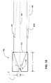
- FIG. 1B schematically illustrates a typical output port 120 of an optical switching device.
- Output port 120 includes an optical fiber tip 121 and a focusing lens 122.
- Output port 120 is configured to receive a collimated light beam at focusing lens 122 and focus the beam onto optical fiber tip 121.
- Beam 123 is a collimated light beam incident on output port 120 that is aligned with an ideal optical axis 124, and therefore is completely focused onto optical fiber tip 121 without any signal loss.
- Beam 125 is a collimated light beam that has a small angular misalignment ⁇ 125 with ideal optical axis 124.
- the focal point of beam 125 is altered as shown by a displacement H from ideal optical axis 124, and is not directed entirely onto optical fiber tip 121, resulting in significant signal loss.
- displacement H may be greater than the radius of optical fiber tip 121, e.g., five or more micrometers, resulting in essentially 100% signal loss.
- focal length L of optical output port 120 is typically several orders of magnitude greater than the diameter of optical fiber tip 121, even small angular misalignment of an incident light beam with optical output port 120 will produce a relatively large displacement H and an associated signal loss.
- Embodiments of the present invention generally provide a fiber lens assembly configured to optically couple an optical fiber to a wavelength division multiplexing (WDM) signal processing device having free-space optical elements.
- WDM wavelength division multiplexing
- a fiber lens assembly comprises an optical fiber for receiving a WDM signal and a diverging lens proximate the optical fiber, for optically coupling the optical fiber with another optical element, the diverging lens having the same optical axis as the optical fiber, a diameter that is greater than a diameter of the optical fiber, and a focal length that is no more than two orders of magnitude greater than the diameter of the optical fiber.
- the fiber lens assembly may be implemented in an input port for a WDM signal processing device, and the diameter of the diverging lens may be about 2 to 6 times greater than the diameter of the optical fiber.
- an optical device for processing a WDM signal comprises a light dispersing element for separating the WDM signal into its wavelength components and combining wavelength components of a WDM signal into the WDM signal, and a fiber lens assembly with an optical fiber and a diverging lens proximate the optical fiber, wherein the diverging lens is configured and positioned to optically couple the optical fiber and the light dispersing element.
- a wavelength selective switch comprises input and output ports, each including a fiber lens assembly with an optical fiber and a diverging lens proximate the optical fiber, a light dispersing element optically coupled to the input and output ports, and an optical switch.
- the optical switch receives wavelength components of an input light beam from the light dispersing element, alters the optical paths of the wavelength components of the input light beam, and directs the wavelength components of the input light beam to the light dispersing element after their optical paths have been altered.
- Figure 1A schematically illustrates the sensitivity of a collimated light beam to angular misalignment of a fiber lens assembly.
- Figure 1B schematically illustrates a typical output port of an optical switching device.
- Figure 2A schematically illustrates a cross-sectional view of a fiber lens assembly, according to an embodiment of the invention.
- Figure 2B illustrates a fiber lens assembly serving as an input port for a signal processing device, according to an embodiment of the invention.
- Figure 2C illustrates a fiber lens assembly serving as an output port for a signal processing device, according to an embodiment of the invention.
- Figure 3 is a vertical plan view of an optical switching device configured with multiple fiber lens assemblies, according to an embodiment of the invention.
- Figure 4 schematically illustrates an optical input/output assembly coupled to a polarization management optics assembly, according to an embodiment of the invention.
- Embodiments of the invention contemplate a fiber lens assembly configured to optically couple an optical fiber to a signal processing device having free-space optical elements. Sensitivity of the fiber lens assembly to angular misalignment and positional displacement is reduced by optically coupling the fiber to the signal processing device using a diverging lens rather than a collimating lens, and by optimizing the focal length of the fiber lens assembly.
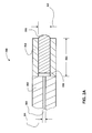
- FIG. 2A schematically illustrates a cross-sectional view of a fiber lens assembly according to an embodiment of the invention.
- Fiber lens assembly 200 includes an optic fiber tip consisting of a core 201 housed in cladding 202.
- Fiber lens assembly 200 also includes a lens element 203 positioned in a lens sheath 204.
- Core 201 has a diameter D1
- lens element 203 is configured with a focal length 205 and a diameter D2.
- diameter D1 is on the order of 10 micrometers
- focal length 205 is no more than two orders of magnitude greater than diameter D1
- diameter D2 is 2 to 6 times diameter D1.
- diameter D2 is 30 to 50 micrometers
- focal length 205 is about 0.5 mm.
- an alignment gap 206 may be present between core 201 and lens element 203.
- fiber lens assembly 200 optically couples core 201 with one or more free-space optical elements of a signal processing device contained in an optical communications network, such as a WSS, OADM, or DGE.
- Fiber lens assembly 200 may serve as an input port or an output port for such a device.
- As an input port fiber lens assembly 200 converts the optical signal contained in core 201 into a free-space divergent light beam for subsequent processing, and as an output port, fiber lens assembly 200 directs a free-space convergent light beam into core 201.
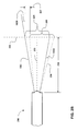
- FIG. 2B illustrates fiber lens assembly 200 configured as an input port for a signal processing device, according to an embodiment of the invention.
- Fiber lens assembly 200 projects a free-space divergent light beam 220 onto ideal target region 221, located on image plane 222.
- Ideal target region 221 corresponds to the location of a diffraction grating, lens, mirror, or other optical element of the signal processing device that requires precise alignment of an incident light beam, i.e., divergent beam 220, for minimal signal loss.
- Divergent light beam 220 is projected from fiber lens assembly 200 with a divergence angle ⁇ 220, where divergence angle ⁇ 220 is optimized based on a number of factors, including the size of ideal target region 221 and the distance 225 between fiber lens assembly 200 and image plane 222.
- fiber lens assembly 200 is centered on ideal optical axis 223. Because of this, divergent light beam 220 crosses a region of image plane 222 that coincides with ideal target region 221, and no signal loss occurs.
- fiber lens assembly 200 directs a divergent light beam 224 toward image plane 222, where divergent beam 224 has angular displacement ⁇ 224 from divergent light beam 220, as shown.
- divergent light beam 224 intersects with image plane 222 at a region 225 that is offset from ideal target region 221 by distance 227.
- Region 225 does not entirely coincide with ideal target region 221, therefore some signal loss occurs.
- signal loss is not a strong function of angular displacement.
- angular displacement ⁇ 224 is equal to divergence angle ⁇ 220
- a significant portion of divergent light beam 224 will be coincident with ideal target region 221.
- signal loss stemming from angular misalignment of fiber lens assembly 200 does not increase when distance 226 between fiber lens assembly 200 and image plane 222 increases.
- Figure 2C illustrates fiber lens assembly 200 configured as an output port for a signal processing device.
- a free-space convergent light beam 230 is projected onto fiber lens assembly 200, which inserts the beam into core 201 for transmission to other regions of an optical network.
- Convergent light beam 230 has a convergence angle ⁇ 230, which is selected based on a number of factors related to the geometrical relationship between fiber lens assembly 200 and the signal processing device optically coupled thereto. With convergent light beam 230 centered on ideal optical axis 231, convergent light beam 230 is focused directly onto core 201 by lens element 203 with essentially no insertion loss.
- lens element 203 directs convergent light beam 232 toward core 201 but displaced a distance 233 from optimum, as shown. In this case, some insertion loss occurs, since a portion of convergent light beam 232 is not directed into core 201. But because focal length 205 is no more than two orders of magnitude larger than diameter D1 of core 201, distance 233 is small relative to diameter D1 for most angular displacements of convergent light beam 232, and the majority of the beam is inserted into core 201. Hence, fiber lens assembly 200 has a relatively low sensitivity to angular misalignment when used as an output port.
- fiber lens assembly 200 is also relatively insensitive to positional displacement. For example, if convergent light beam 230 is vertically displaced 10 micrometers relative to ideal optical axis 231, the majority of the beam will still be inserted into core 201. In contrast, for a prior art fiber lens assembly, in which the diameter of the lens element is approximately the same as that of the fiber core, a 10 micrometer displacement of convergent light beam 230 will result in 100% insertion loss, since the beam will completely miss the lens element.
- FIG 3 is a vertical plan view of an optical switching device configured with multiple fiber lens assemblies, according to an embodiment of the invention.
- WSS 300 is a 1 x 4 wavelength selective switch and includes an optical input/output assembly 360, a base unit 310, and a switching optics assembly 330.
- the components of WSS 300 are mounted on a planar surface 390 that is herein defined as the horizontal plane for purposes of description, and which serves as a support structure and optical datum plane for the components of WSS 300.
- optical input/output assembly 360 optically couples a single WDM optical input signal from a communications network to WSS 300 and four optical output signals from WSS 300 back to the communications network.
- Optical input/output assembly 360 includes multiple fiber lens assemblies to perform the optical coupling between WSS 300 and the communications network.
- Optical input/output assembly 360 includes one input port 301 and four output ports 302A-D, where input port 301 and output ports 302A-D are fiber lens assemblies substantially similar to fiber lens assembly 200, described above in conjunction with Figure 2A .
- Base unit 310 is made up of a plurality of free-space optical elements, including a folding mirror 313, beam steering unit 314, cylindrical lenses 315 and 316, a light dispersing element 317, a folding mirror 322, cylindrical lens 321, a focusing lens 323, and a beam polarization unit 331.
- Light dispersing element 317 may be a diffraction grating or an arrayed waveguide grating.
- Base unit 310 optically couples optical input/output assembly 360 with switching optics assembly 330. In directing inbound light beams from input port 301 to switching optics assembly 330, base unit 310 shapes, separates, and focuses inbound light beams onto beam polarization unit 331. In directing outbound light beams back to optical input/output assembly 360, base unit 310 recombines, shapes, and directs outbound light beams to one or more of optical output ports 302A-D contained in optical input/output assembly 360.
- Switching optics assembly 330 performs switching, attenuation, or other desired functions on an optical input signal, and includes an LC-based beam polarization unit 331, collimating lenses 332, 333, a beam steering unit 334, collimating lenses 335, 336, and an LC-based beam displacer assembly 337.
- Beam steering unit 334 may be a birefringent crystal or a Wollaston prism.
- the elements of switching optics assembly 330 are optically linked to enable the optical routing of a WDM optical input signal entering optical input port 301 to any one of the optical output ports 302A-D.
- the optical routing is performed by conditioning (via LC polarization) and vertically displacing inbound beams to produce outbound beams having a desired vertical position and polarization state.
- Switching optics assembly 330 selectively determines the vertical displacement of the outbound beams to correspond to the vertical position of the desired output port, i.e ., optical output port 302A, 302B, 302C, or 302D, hence performing a 1 x 4 optical switching operation.
- WSS 300 is optically coupled to a communications network with one or more fiber lens assemblies according to embodiments of the invention, signal loss associated with such unwanted positional displacement is significantly reduced or eliminated.
- optical input/output assembly 360 the effect of positional errors associated with installation of a fiber lens assembly onto WSS 300 can be minimized.
- vertical irregularities on planar surface 390 may produce unwanted positional displacement between an input port and an output port.
- input port 301 and output ports 302A-D into a single assembly, positional errors caused by vertical irregularities on planar surface 390 are minimized.
- input port 301 and output port 302A are each mounted in different locations on substrate 303, one may be positioned on a relative high spot on planar surface 390 and the other on a relative low spot on planar surface 390, thereby compounding the variation in flatness of planar surface 390. In so doing, significant vertical positional error may be produced, which may adversely affect the alignment of input port 301 and output port 302A to base unit 310 and to each other.
- WDM signal processing devices such as optical add-drop multiplexers or dynamic gain equalizers, may also benefit when optically coupled to a communications network via one or more fiber lens assemblies, according to embodiments of the invention.
- a WDM signal processing device is less sensitive to precise alignment and positioning of optical input and output ports to the optical axis of the device.
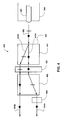
- optical input/output assembly 360 is coupled to a polarization management optics assembly 400, as illustrated schematically in Figure 4 .
- Polarization management optics assembly 400 receives an optical input signal 410 from a fiber lens assembly 200 contained in optical input/output assembly 360, where optical input signal 410 corresponds to a WDM optical signal that is directed to WSS 300 in Figure 3 from a communications network. Because the polarization state of optical input signal 410 may be arbitrary and/or unknown, polarization management optics assembly 400 adjusts the polarization of the WDM optical input signal to a single, known state, i.e., linearly polarized in a known direction.
- Polarization management optics assembly 400 includes a first birefringent beam displacer 401, a second birefringent beam displacer 402, a full-sized half-wave plate 403, and a half-sized half-wave plate 404, arranged as shown in Figure 4 .
- First birefringent beam displacer 401 and second birefringent beam displacer 402 are optical components that have a different refractive index depending on the polarization state of incident light, such as a YVO 4 cube. Consequently, the s-polarized and p-polarized components of a light beam follow different paths when passing through first birefringent beam displacer 401 and second birefringent beam displacer 402.
- first birefringent beam displacer 401 is substantially identical to the configuration of second birefringent beam displacer 402, including physical dimensions and optical properties.
- first birefringent beam displacer 401 and second birefringent beam displacer 402 may each have different optical and dimensional properties that are selected to provide the same optical processing of optical input signal 410 as described herein.
- polarization management optics assembly 400 receives optical input signal 410 from optical input/output assembly 360 on surface 405 of first birefringent beam displacer 401. From surface 405, optical input signal 410 is split into a first component 410A and a second component 410B, which are initially s- and p-polarized, respectively, as indicated.
- First birefringent beam displacer 401 is oriented with respect to optical input signal 410 to direct s-polarized light, e.g. , first component 410A, along an unaltered path and p-polarized light, e.g ., second component 410B, along an angularly displaced path.
- first component 410A and second component 410B Upon exiting first birefringent beam displacer 401, first component 410A and second component 410B return to parallel paths. Full-sized half-wave plate 403 the rotates the polarization state of first component 410A and second component 410B, so that first component 410A is p-polarized prior to entering second birefringent beam displacer 402 and second component 410B is s-polarized prior to entering second birefringent beam displacer 402. Thus, first component 410A follows an angularly displaced path through second birefringent beam displacer 402 and second component 410B passes directly through second birefringent beam displacer 402 without undergoing angular displacement.
- first component 410A and second component 410B Upon exiting second birefringent beam displacer 402, first component 410A and second component 410B once again return to parallel paths. First component 410A then passes through half-sized half-wave plate 404 and is changed from p-polarized to s-polarized light. In this way, optical input signal 410, which has an arbitrary polarization state, is converted into two closely space, parallel light beams, i.e ., first component 410A and second component 410B, having a single, known polarization state, i.e. , s-polarized. Because the two parallel beams are closely spaced, the various active and passive optical elements of WSS 300 may treat these two beams as essentially one beam throughout WSS 300.
- optical input/output assembly 360 may only include second birefringent beam displacer 402 and half-sized half-wave plate 404 to convert optical input signal 410 into two closely spaced, parallel light beams.
- the optical paths of first component 410A and second component 410B have different lengths, and may cause one or more of the following: polarization mode dispersion (PMD), polarization dependent losses (PDL), insertion loss due to optical aberration, and a decrease in the bandpass of the LC-based optical switching components of WSS 300 located "downstream" of polarization management optics assembly 400.
- PMD polarization mode dispersion
- PDL polarization dependent losses
- insertion loss due to optical aberration and a decrease in the bandpass of the LC-based optical switching components of WSS 300 located "downstream" of polarization management optics assembly 400.
- full-sized half-wave plate 403 and first birefringent beam displacer 401 are included in polarization management optics assembly 400 so that the optical paths of
Landscapes
- Physics & Mathematics (AREA)
- General Physics & Mathematics (AREA)
- Optics & Photonics (AREA)
- Optical Couplings Of Light Guides (AREA)
Applications Claiming Priority (2)
| Application Number | Priority Date | Filing Date | Title |
|---|---|---|---|
| US89387207P | 2007-03-08 | 2007-03-08 | |
| US12/014,728 US8094982B2 (en) | 2007-03-08 | 2008-01-15 | Fiber lens assembly for optical device |
Publications (1)
| Publication Number | Publication Date |
|---|---|
| EP1970754A1 true EP1970754A1 (de) | 2008-09-17 |
Family
ID=39427523
Family Applications (1)
| Application Number | Title | Priority Date | Filing Date |
|---|---|---|---|
| EP08152468A Withdrawn EP1970754A1 (de) | 2007-03-08 | 2008-03-07 | Faserlinsenanordnung und optische Vorrichtung |
Country Status (2)
| Country | Link |
|---|---|
| US (1) | US8094982B2 (de) |
| EP (1) | EP1970754A1 (de) |
Families Citing this family (6)
| Publication number | Priority date | Publication date | Assignee | Title |
|---|---|---|---|---|
| US8346084B2 (en) * | 2007-03-08 | 2013-01-01 | Oclaro (North America), Inc. | Optical device with stable optical configuration |
| US8203691B2 (en) | 2007-03-08 | 2012-06-19 | Oclaro (North America), Inc. | High extinction ratio liquid crystal optical switch |
| CN102082393B (zh) * | 2010-11-22 | 2011-12-28 | 山东华光光电子有限公司 | 一种半导体激光器双弧面镀膜光纤整形方法 |
| US9372310B1 (en) | 2014-12-19 | 2016-06-21 | Gooch And Housego Plc | Free space fibre-to-fibre coupling using optical fibres below cut-off |
| US20230258965A1 (en) * | 2020-07-09 | 2023-08-17 | National University Of Singapore | Method and device for optical power limiter |
| US20240382091A1 (en) * | 2023-05-16 | 2024-11-21 | Twenty Twenty Therapeutics Llc | System for measurement of an intraocular implant |
Citations (4)
| Publication number | Priority date | Publication date | Assignee | Title |
|---|---|---|---|---|
| US5280555A (en) * | 1993-02-02 | 1994-01-18 | Ainsburg David P | Visual accident prevention system |
| US6757113B1 (en) * | 2003-03-18 | 2004-06-29 | Lucent Technologies Inc. | Optical grating mount |
| EP1523212A2 (de) * | 2003-10-07 | 2005-04-13 | Agilent Technologies, Inc. | Verfahren und Vorrichtung zur wellenlängen-selektiven und polarisation-abhängigen Vermittlung |
| WO2006015795A1 (de) * | 2004-08-05 | 2006-02-16 | Kuka Schweissanlagen Gmbh | Lasereinrichtung und betriebsverfahren |
Family Cites Families (15)
| Publication number | Priority date | Publication date | Assignee | Title |
|---|---|---|---|---|
| JP3322712B2 (ja) * | 1993-01-14 | 2002-09-09 | 松下電器産業株式会社 | 光チューナの起動方法及び光チューナ |
| US6320996B1 (en) * | 1998-12-31 | 2001-11-20 | Optical Coating Laboratory, Inc. | Wavelength selective optical switch |
| US6594082B1 (en) * | 2000-06-05 | 2003-07-15 | Avanex Corporation | Optical wavelength router using reflective surfaces to direct output signals |
| US6563977B1 (en) * | 2000-06-27 | 2003-05-13 | Bayspec, Inc. | Compact wavelength multiplexer-demultiplexer providing low polarization sensitivity |
| KR100342493B1 (ko) * | 2000-07-25 | 2002-06-28 | 윤종용 | 회절 효과를 최소화하기 위한 광섬유 격자 제작장치 |
| WO2002082166A2 (en) * | 2001-04-03 | 2002-10-17 | Cidra Corporation | Variable optical source |
| CA2443356A1 (en) * | 2001-04-03 | 2002-10-17 | Cidra Corporation | Dynamic optical filter having a spatial light modulator |
| DE10143252A1 (de) * | 2001-09-04 | 2003-03-20 | Sms Demag Ag | Vorrichtung zum Auftragen von Schmierstoffen auf die Umfangsfläche von Walzen in Walzgerüsten |
| WO2003032071A1 (en) * | 2001-10-09 | 2003-04-17 | Xtellus Inc. | Wavelength selective optical switch |
| US20030190121A1 (en) * | 2002-04-09 | 2003-10-09 | Fang Luo | Athermal tunable filter with wavelength and intensity responses based on volume phase hologram |
| US6825981B2 (en) * | 2002-10-10 | 2004-11-30 | Sumitomo Electric Industries, Ltd. | Optical signal processor |
| US7126696B2 (en) * | 2003-09-30 | 2006-10-24 | Mitutoyo Corporation | Interferometric miniature grating encoder readhead using fiber optic receiver channels |
| CN103293126B (zh) * | 2003-10-27 | 2017-03-01 | 通用医疗公司 | 用于使用频域干涉测量法进行光学成像的方法和设备 |
| US7257288B1 (en) * | 2004-04-23 | 2007-08-14 | Nistica, Inc. | Tunable optical routing systems |
| US7408639B1 (en) * | 2004-04-23 | 2008-08-05 | Nistica, Inc. | Tunable optical routing systems |
-
2008
- 2008-01-15 US US12/014,728 patent/US8094982B2/en active Active
- 2008-03-07 EP EP08152468A patent/EP1970754A1/de not_active Withdrawn
Patent Citations (4)
| Publication number | Priority date | Publication date | Assignee | Title |
|---|---|---|---|---|
| US5280555A (en) * | 1993-02-02 | 1994-01-18 | Ainsburg David P | Visual accident prevention system |
| US6757113B1 (en) * | 2003-03-18 | 2004-06-29 | Lucent Technologies Inc. | Optical grating mount |
| EP1523212A2 (de) * | 2003-10-07 | 2005-04-13 | Agilent Technologies, Inc. | Verfahren und Vorrichtung zur wellenlängen-selektiven und polarisation-abhängigen Vermittlung |
| WO2006015795A1 (de) * | 2004-08-05 | 2006-02-16 | Kuka Schweissanlagen Gmbh | Lasereinrichtung und betriebsverfahren |
Also Published As
| Publication number | Publication date |
|---|---|
| US20080219619A1 (en) | 2008-09-11 |
| US8094982B2 (en) | 2012-01-10 |
Similar Documents
| Publication | Publication Date | Title |
|---|---|---|
| US6701043B2 (en) | Arrayed waveguide grating having a reflective input coupling | |
| USRE47906E1 (en) | Reconfigurable optical add-drop multiplexers with servo control and dynamic spectral power management capabilities | |
| US6859573B2 (en) | Double pass arrangement for a liquid crystal device | |
| US7826697B2 (en) | System and method for asymmetrical fiber spacing for wavelength selective switches | |
| EP3304154B1 (de) | Optische kopplung mit verwendung von polarisationsstrahlverdränger | |
| USRE39411E1 (en) | Reconfigurable all-optical multiplexers with simultaneous add-drop capability | |
| USRE42521E1 (en) | Reconfigurable optical add-drop multiplexers employing polarization diversity | |
| US6442310B1 (en) | Optical coupling device and method | |
| US8094982B2 (en) | Fiber lens assembly for optical device | |
| US6860644B2 (en) | Dual fiber collimator assembly pointing control | |
| US8346084B2 (en) | Optical device with stable optical configuration | |
| KR20040016406A (ko) | 광 모듈 | |
| US20060159395A1 (en) | Optical compensator array for dispersive element arrays | |
| US6925227B2 (en) | Optical device | |
| US20080219668A1 (en) | Liquid crystal optical device with arrayed waveguide grating | |
| JP4252678B2 (ja) | 光合分波モジュール | |
| US7218857B1 (en) | Method, apparatus and system for a re-configurable optical add-drop multiplexer | |
| US7277607B2 (en) | Optical multiplexer/demultiplexer, optical device, and optical transmission system | |
| US6829403B2 (en) | Optical switch having an array of optical fibers with respective, removable disposed mirrors and a lens disposed away from an end surface of each corresponding optical fiber | |
| US20030095749A1 (en) | Fiber coupler and compensation system | |
| JPH07111489B2 (ja) | 光分波器 | |
| JPH05181035A (ja) | 光分波・分岐デバイス |
Legal Events
| Date | Code | Title | Description |
|---|---|---|---|
| PUAI | Public reference made under article 153(3) epc to a published international application that has entered the european phase |
Free format text: ORIGINAL CODE: 0009012 |
|
| AK | Designated contracting states |
Kind code of ref document: A1 Designated state(s): AT BE BG CH CY CZ DE DK EE ES FI FR GB GR HR HU IE IS IT LI LT LU LV MC MT NL NO PL PT RO SE SI SK TR |
|
| AX | Request for extension of the european patent |
Extension state: AL BA MK RS |
|
| 17P | Request for examination filed |
Effective date: 20081208 |
|
| 17Q | First examination report despatched |
Effective date: 20090128 |
|
| AKX | Designation fees paid |
Designated state(s): DE FR GB IT |
|
| STAA | Information on the status of an ep patent application or granted ep patent |
Free format text: STATUS: THE APPLICATION IS DEEMED TO BE WITHDRAWN |
|
| 18D | Application deemed to be withdrawn |
Effective date: 20091007 |