EP1970426A1 - Separation process and apparatus for removal of particulate material from delayed coking gas oil - Google Patents
Separation process and apparatus for removal of particulate material from delayed coking gas oil Download PDFInfo
- Publication number
- EP1970426A1 EP1970426A1 EP08006501A EP08006501A EP1970426A1 EP 1970426 A1 EP1970426 A1 EP 1970426A1 EP 08006501 A EP08006501 A EP 08006501A EP 08006501 A EP08006501 A EP 08006501A EP 1970426 A1 EP1970426 A1 EP 1970426A1
- Authority
- EP
- European Patent Office
- Prior art keywords
- separator
- stream
- gas oil
- particulate
- micrometers
- Prior art date
- Legal status (The legal status is an assumption and is not a legal conclusion. Google has not performed a legal analysis and makes no representation as to the accuracy of the status listed.)
- Withdrawn
Links
Images
Classifications
-
- C—CHEMISTRY; METALLURGY
- C10—PETROLEUM, GAS OR COKE INDUSTRIES; TECHNICAL GASES CONTAINING CARBON MONOXIDE; FUELS; LUBRICANTS; PEAT
- C10G—CRACKING HYDROCARBON OILS; PRODUCTION OF LIQUID HYDROCARBON MIXTURES, e.g. BY DESTRUCTIVE HYDROGENATION, OLIGOMERISATION, POLYMERISATION; RECOVERY OF HYDROCARBON OILS FROM OIL-SHALE, OIL-SAND, OR GASES; REFINING MIXTURES MAINLY CONSISTING OF HYDROCARBONS; REFORMING OF NAPHTHA; MINERAL WAXES
- C10G9/00—Thermal non-catalytic cracking, in the absence of hydrogen, of hydrocarbon oils
-
- B—PERFORMING OPERATIONS; TRANSPORTING
- B01—PHYSICAL OR CHEMICAL PROCESSES OR APPARATUS IN GENERAL
- B01J—CHEMICAL OR PHYSICAL PROCESSES, e.g. CATALYSIS OR COLLOID CHEMISTRY; THEIR RELEVANT APPARATUS
- B01J8/00—Chemical or physical processes in general, conducted in the presence of fluids and solid particles; Apparatus for such processes
- B01J8/005—Separating solid material from the gas/liquid stream
- B01J8/0055—Separating solid material from the gas/liquid stream using cyclones
-
- C—CHEMISTRY; METALLURGY
- C10—PETROLEUM, GAS OR COKE INDUSTRIES; TECHNICAL GASES CONTAINING CARBON MONOXIDE; FUELS; LUBRICANTS; PEAT
- C10B—DESTRUCTIVE DISTILLATION OF CARBONACEOUS MATERIALS FOR PRODUCTION OF GAS, COKE, TAR, OR SIMILAR MATERIALS
- C10B55/00—Coking mineral oils, bitumen, tar, and the like or mixtures thereof with solid carbonaceous material
-
- C—CHEMISTRY; METALLURGY
- C10—PETROLEUM, GAS OR COKE INDUSTRIES; TECHNICAL GASES CONTAINING CARBON MONOXIDE; FUELS; LUBRICANTS; PEAT
- C10G—CRACKING HYDROCARBON OILS; PRODUCTION OF LIQUID HYDROCARBON MIXTURES, e.g. BY DESTRUCTIVE HYDROGENATION, OLIGOMERISATION, POLYMERISATION; RECOVERY OF HYDROCARBON OILS FROM OIL-SHALE, OIL-SAND, OR GASES; REFINING MIXTURES MAINLY CONSISTING OF HYDROCARBONS; REFORMING OF NAPHTHA; MINERAL WAXES
- C10G55/00—Treatment of hydrocarbon oils, in the absence of hydrogen, by at least one refining process and at least one cracking process
- C10G55/02—Treatment of hydrocarbon oils, in the absence of hydrogen, by at least one refining process and at least one cracking process plural serial stages only
- C10G55/04—Treatment of hydrocarbon oils, in the absence of hydrogen, by at least one refining process and at least one cracking process plural serial stages only including at least one thermal cracking step
-
- C—CHEMISTRY; METALLURGY
- C10—PETROLEUM, GAS OR COKE INDUSTRIES; TECHNICAL GASES CONTAINING CARBON MONOXIDE; FUELS; LUBRICANTS; PEAT
- C10G—CRACKING HYDROCARBON OILS; PRODUCTION OF LIQUID HYDROCARBON MIXTURES, e.g. BY DESTRUCTIVE HYDROGENATION, OLIGOMERISATION, POLYMERISATION; RECOVERY OF HYDROCARBON OILS FROM OIL-SHALE, OIL-SAND, OR GASES; REFINING MIXTURES MAINLY CONSISTING OF HYDROCARBONS; REFORMING OF NAPHTHA; MINERAL WAXES
- C10G55/00—Treatment of hydrocarbon oils, in the absence of hydrogen, by at least one refining process and at least one cracking process
- C10G55/02—Treatment of hydrocarbon oils, in the absence of hydrogen, by at least one refining process and at least one cracking process plural serial stages only
- C10G55/06—Treatment of hydrocarbon oils, in the absence of hydrogen, by at least one refining process and at least one cracking process plural serial stages only including at least one catalytic cracking step
-
- C—CHEMISTRY; METALLURGY
- C10—PETROLEUM, GAS OR COKE INDUSTRIES; TECHNICAL GASES CONTAINING CARBON MONOXIDE; FUELS; LUBRICANTS; PEAT
- C10G—CRACKING HYDROCARBON OILS; PRODUCTION OF LIQUID HYDROCARBON MIXTURES, e.g. BY DESTRUCTIVE HYDROGENATION, OLIGOMERISATION, POLYMERISATION; RECOVERY OF HYDROCARBON OILS FROM OIL-SHALE, OIL-SAND, OR GASES; REFINING MIXTURES MAINLY CONSISTING OF HYDROCARBONS; REFORMING OF NAPHTHA; MINERAL WAXES
- C10G69/00—Treatment of hydrocarbon oils by at least one hydrotreatment process and at least one other conversion process
- C10G69/02—Treatment of hydrocarbon oils by at least one hydrotreatment process and at least one other conversion process plural serial stages only
- C10G69/04—Treatment of hydrocarbon oils by at least one hydrotreatment process and at least one other conversion process plural serial stages only including at least one step of catalytic cracking in the absence of hydrogen
-
- C—CHEMISTRY; METALLURGY
- C10—PETROLEUM, GAS OR COKE INDUSTRIES; TECHNICAL GASES CONTAINING CARBON MONOXIDE; FUELS; LUBRICANTS; PEAT
- C10G—CRACKING HYDROCARBON OILS; PRODUCTION OF LIQUID HYDROCARBON MIXTURES, e.g. BY DESTRUCTIVE HYDROGENATION, OLIGOMERISATION, POLYMERISATION; RECOVERY OF HYDROCARBON OILS FROM OIL-SHALE, OIL-SAND, OR GASES; REFINING MIXTURES MAINLY CONSISTING OF HYDROCARBONS; REFORMING OF NAPHTHA; MINERAL WAXES
- C10G69/00—Treatment of hydrocarbon oils by at least one hydrotreatment process and at least one other conversion process
- C10G69/02—Treatment of hydrocarbon oils by at least one hydrotreatment process and at least one other conversion process plural serial stages only
- C10G69/06—Treatment of hydrocarbon oils by at least one hydrotreatment process and at least one other conversion process plural serial stages only including at least one step of thermal cracking in the absence of hydrogen
-
- C—CHEMISTRY; METALLURGY
- C10—PETROLEUM, GAS OR COKE INDUSTRIES; TECHNICAL GASES CONTAINING CARBON MONOXIDE; FUELS; LUBRICANTS; PEAT
- C10G—CRACKING HYDROCARBON OILS; PRODUCTION OF LIQUID HYDROCARBON MIXTURES, e.g. BY DESTRUCTIVE HYDROGENATION, OLIGOMERISATION, POLYMERISATION; RECOVERY OF HYDROCARBON OILS FROM OIL-SHALE, OIL-SAND, OR GASES; REFINING MIXTURES MAINLY CONSISTING OF HYDROCARBONS; REFORMING OF NAPHTHA; MINERAL WAXES
- C10G9/00—Thermal non-catalytic cracking, in the absence of hydrogen, of hydrocarbon oils
- C10G9/005—Coking (in order to produce liquid products mainly)
-
- B—PERFORMING OPERATIONS; TRANSPORTING
- B01—PHYSICAL OR CHEMICAL PROCESSES OR APPARATUS IN GENERAL
- B01J—CHEMICAL OR PHYSICAL PROCESSES, e.g. CATALYSIS OR COLLOID CHEMISTRY; THEIR RELEVANT APPARATUS
- B01J2219/00—Chemical, physical or physico-chemical processes in general; Their relevant apparatus
- B01J2219/00002—Chemical plants
- B01J2219/00004—Scale aspects
- B01J2219/00006—Large-scale industrial plants
Definitions
- the present invention relates to delayed coking processes, and more particularly to a process and an apparatus for removal of particulate material from a flash zone gas oil stream in a delayed coking unit.
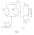
- a delayed coking process overhead vapors from a coke drum are passed to a coke fractionator wherein the coker overheads are separated into a vapor stream, one or more intermediate liquid streams, and a flash zone gas oil (FZGO) stream.
- the FZGO stream often contains significant amounts of finely divided particulate solids (e.g. coke fines) of varying diameter, as well as heavy viscous mesophase material.
- the mesophase material can be liquid coke that is entrained in the vapors leaving a coke drum and is often coated on coke particles, making the particles sticky.
- FZGO stream In order to enhance the value of an FZGO stream, further processing is necessary, and it is desirable to pass the FZGO stream to, for example, a fixed bed catalytic hydroprocessing unit and then to a fluidized bed catalytic cracking (FCC) unit or to other processing units.
- FCC fluidized bed catalytic cracking
- entrained solids and mesophase material in the FZGO stream can Quickly plug and foul the catalyst bed of the hydroprocessor.
- Unhydrotreated flash zone gas oil can be processed in a fluidized bed catalytic cracking unit (FCC unit), but the yield distribution of the unhydrotreated FZGO stream is generally poor due to its highly aromatic content and other factors.
- FCC unit fluidized bed catalytic cracking unit
- a filter medium can be used to filter out particles from the FZGO stream.
- filtration processes are susceptible to filter plugging, can require significant periods of shutdown to clean or remove tar or gum build up to regenerate the filter medium, and can require significant initial capital expenditure to install.
- the present invention provides a process and an apparatus for removing particulate material from a flash zone gas oil stream, including particulates that are about 15 micrometers to 25 micrometers or more in diameter.
- cyclonic separation technology is used to centrifugally remove particulate material from the FZGO stream to form a reduced particulate stream.
- the reduced particulate stream can then be further processed, for example, in a hydroprocessing unit and subsequent fluidized bed catalytic cracking (FCC) unit, to provide valuable products.
- an improved delayed coking process wherein overhead vapors from a coking drum are fed to a coker fractionator where the vapors are separated into an overhead vapor stream, intermediate liquid streams, and a flash zone gas oil stream containing a substantial amount of particulate material of varying diameter, the improved process further comprising the steps of:
- the invention is an apparatus comprising a coking drum that generates overhead vapors, a coker fractionator that receives the overhead vapors from the coking drum and separates them into an overhead vapor stream, intermediate liquid streams, and a flash zone gas oil stream containing a substantial amount of particulate material of varying diameter, and a hydroprocessor located downstream from said fractionator, the improved apparatus further comprising:
- an apparatus that includes two separators is provided, where at least one of the separators is a cyclonic separator having a manifold of cyclones.
- the process and apparatus of the invention can advantageously operate continuously on-line without periodic shut downs for back flushing clogged equipment, resulting in lower maintenance and operating costs. Compared to conventional methods, the process and apparatus of the invention can advantageously be implemented with a low initial capital cost. The process and apparatus of the invention also present an opportunity for improving refinery economics by facilitating further processing of the FZGO stream and permitting the use of hydrotreated FZGO as FCC unit feedstock rather than as delayed coker natural recycle.
- a FZGO stream 60 is generally not fed to a hydrotreater due to rapid catalyst fouling from the suspended particulate material.
- the FZGO stream maybe fed unfiltered to an FCC unit.
- the oil stream's high level of aromatic compounds results in poor product yield distribution.
- the FZGO stream often contains undesirable levels of sulfur and could cause the stream exiting the FCC unit to exceed the industry mandated sulfur levels in the gasoline, kerosene and diesel product streams of the refinery.
- an FZGO stream would be used as lower value stream such as those used to produce high sulfur fuel oil.
- Removing particulate material from an FZGO stream advantageously enhances the value of an oil stream by allowing it to be processed further to obtain useful and valuable products.
- a reduced particulate oil stream could be fed to a fixed bed catalytic hydrotreater without fear of fouling the catalyst bed.
- directing all FZGO stream 60 such as that obtained from a process depicted in FIG. 1 to a separation process would be desirable, as it can be further processed in units such as an FCC unit to produce valuable products.
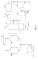
- the present invention provides an improved process and apparatus for separating particulate material suspended in a flash zone oil stream from the oil stream itself, using at least one cyclonic separation unit or separator.
- the second separator is a cyclonic unit comprising a plurality of cyclones provided in a manifold. This separator is implemented to remove particulate material that have a diameter of greater than about 15 micrometers from an oil stream that is ultimately intended to enter a catalytic cracking unit.
- a separator located upstream from the cyclonic separator can be implemented to remove larger particulate material that are greater than about 75 micrometer in diameter, to prevent plugging of the cyclonic separator.
- separator 65 preferably removes the larger particles from the FZGO stream, such as those having a diameter greater than about 500 micrometers.
- Cyclonic separator 80 substantially separates and removes the smaller particles, such as those having a diameter greater than about 25 micrometers. If a "cleaner" oil stream is desired, separator 65 can be configured to separate particulate material having a diameter greater than about 100 micrometers; and preferably, particulate having a diameter greater than about 75 micrometers. Similarly, for "cleaner" oil streams, cyclonic separator 80 removes particulate material having a diameter greater than about 15 micrometers.
- separation unit 65 separates at least about 80% of the particulate that has a diameter greater than about 500 micrometers. More preferably, unit 65 separates at least about 90% of the particulate greater than about 500 micrometers. Similar levels of separation efficiency would be desirable for particulate material having a diameter greater than about 100 micrometers, as well as for particulate material having a diameter greater than about 75 micrometers.
- Separator 65 can be any device capable of separating, displacing, removing, stripping, filtering, or combinations thereof, the particulate material (e.g. solids and other non-fluids) from a fluid stream.
- Suitable devices for separator 65 include for example, a strainer, a sieve, a filter, a cyclonic separator, or combinations thereof
- separator 65 is a basket strainer.
- the strainer can include a wire mesh of about 75 to about 100 micrometers.
- Other suitable designs include, for example, a duplex or a simplex strainer.
- separator 65 comprises a cyclonic separator. This will be described in greater detail in the discussion about FIG. 3 below.
- a reduced particulate oil stream 70 exits separator 65 and is subsequently fed downstream to cyclonic separator 80.
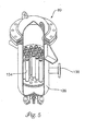
- cyclonic separator 80 includes a plurality of individual, preferably small-sized, cyclones contained within a manifold, inside a housing or vessel.
- a preferred separator 80 is illustrated in FIG. 5 , the contents of which will be discussed in detail below.
- cyclonic separator 80 separates at least about 80% of the particulate having a diameter greater than about 25 micrometers. More preferably, unit 80 is configured to separate at least about 90% of the particulate greater than about 25 micrometers. Similar levels of separation efficiency would be desirable for particulate material having a diameter greater than about 15 micrometers.
- Overflow stream 90 from cyclonic separator 80, having a reduced particulate level, can be fed to a hydroprocessing unit 95 where it is processed to be suitable for further processing in a catalytic cracking unit 100, such as a fluidized bed catalytic cracker (FCC).
- a catalytic cracking unit 100 such as a fluidized bed catalytic cracker (FCC).
- An underflow stream 85 exits the lower region of cyclonic separator 80, carrying away the particulate material displaced from the oil stream 70.
- Hydroprocessor 95 may be a hydrotreater, a hydrocracking unit, or a hydrodesulfurizer, and typically includes a fixed bed catalyst.
- an optional stream of heavy gas oil 55 may be supplied as a feed stream 55A directly to separator 65 to act as a diluent which makes the stream less viscous. This helps prevent.plugging of the line, as the stream is carried back to the cyclone 80.
- a heavy coker gas oil (“HCGO”) can be admixed to an underflow stream leaving a separator to avoid plugging the underflow lines.
- the HCGO can be both a flush oil as well as a distillate recycle to dilute the concentration of coke particles in the stream.
- Use of an HCGO stream also increases the total liquid volume within the process and helps maintain necessary flow velocities in the process' conduits.
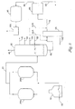
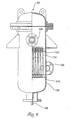
- FIG. 3 provides another embodiment of the present invention wherein separation of particulates from an FZGO stream is accomplished using a series of cyclonic separators.
- separator 65 is a cyclonic separation unit preferably configured and designed sufficiently large to operate at commercial-coking flow rates; temperatures, and separation efficiencies.
- unit 65 is operated to substantially remove large particulate material having a diameter greater than about 500 micrometers, while downstream cyclonic separator 80 removes the smaller particles.
- separator 65 removes particulate having a diameter greater than about 100 micrometers and more preferably particulate having a diameter greater than about 75 micrometers.
- cyclonic separator 80 can be operated efficiently, with the potential or frequency of plugging minimized if not eliminated.
- separator 65 operates at separation efficiencies (percent removal) similar to that described above in FIG. 2 .
- the nominal diameter of a cyclonic separator 65 is preferably between about four and ten inches. This may change, however, depending on the length of the vessel, desired throughput, and/or other process parameters that could affect the separation process.
- FZGO stream 60 enters separator 65, where it is processed to remove the larger particulates from the FZGO.
- An overflow stream 70 having a reduced level of particulate material exits separator 65, while an underflow stream 110 exits the lower region of separator 65.
- Underflow stream 110 contains the centrifugally displaced particulates from FZGO stream 60.
- a separator such as 65 or 80 is operated with a pressure drop sufficient to sustain the volumes and flow rate through the process. Furthermore, it has been found that sufficient pressure drop can ensure efficient, unencumbered operation of a separator.
- separator 65 is a cyclonic vessel as shown in FIG. 3
- the unit is preferably operated with a pressure drop of at least 10 psig. More preferably, the unit is operated with a pressure drop of at least 20 psig.
- cyclonic separator 80 is operated with a pressure drop of at least 25 psig; more preferably, the pressure drop is at least 50 psig.
- heavy gas oil streams 55A and 55B produced by fractionator 30 can be directed to unit 65 and 80, respectively, as shown in FIG. 3 .
- Directing stream 55A to separator 65 may be advantageous where a significant amount of large particles are in the heavy gas oil stream. If there are very few large particles, then stream 55B is preferably directed to separator unit 80 to reduce the pump pressure requirements.
- an optional stream of distillate flush oil can be mixed with underflow stream 110 to prevent plugging of the underflow lines.
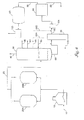
- a further embodiment of the invention includes at least three separation units as shown in FIG. 4 .
- the third separator 105 is preferably located downstream for separator 65 and upstream from separator 80.
- Separator 105 can be yet another cyclonic separator, a strainer, a filter, or any other solid removal device.
- the separation device in unit 105 is preferably deigned to be capable of removing particulate material from an oil stream, and therefore serves to be either a back-up for periods when unit 65 is inoperative or down, or as a second assurance that large particulate are removed from the oil stream prior to entering cyclonic separator 80.
- the underflow stream 85 originating from cyclonic separator 80 can be combined with the underflow stream 110 from separator 65 to form a combined underflow stream (not shown) that can be returned to coker fractionator 30 as natural recycle.
- a moderate amount of the combined stream is preferably used.
- the volume of the two combined underflow streams, not including any distillate flush oil with which they are mixed, is preferably less than about 5% of the total FZGO stream, but can be as low as about 1.5% of the total FZGO stream.
- the flow rate of the various streams within the process can be controlled with a variety of instrumentation and equipment as is known in the art.
- additional equipment and apparatuses such as valves, controllers, flowmeters, indicators, etc., can be added to the process, although not depicted in the flowsheets of FIGS. 1-4 .
- the use of a heavy coker gas oil can also be added as a flush oil to alleviate potential plugging in the process.
- Cyclonic separators useful for the methods of the invention are those modeled after cyclones, where elongate vessels are designed with inlet ports strategically placed tangential to the vessel body, such that a vortex is produced as fluid flows into the vessel. Using centrifugal force, denser material (e.g, solids or particulate material) are removed and separated from the FZGO stream.
- Cyclonic separators, suitable, for the invention can range in size (e.g., nominal diameter) from about 0.5 inch to about 15 inches. The size (e.g. diameter of a single cyclone to remove large particulate, or the number of cyclones in a multi-cyclone unit) can vary, as the size is determined by an intended quantity (volume) of fluid throughput.
- a cyclonic separation unit For acceptable operation of a cyclonic separator in a delayed coking process of the invention, several factors could determine how a cyclonic separation unit is designed and configured (e.g, size, diameter, length). These factors include, for example, the desired liquid throughput, the size of particles intended to be removed, and process efficiency. Determining the cyclone size is generally the first step; the flow rate through the apparatus can then be determined based on that size. For multiple cyclone units (i.e. a manifold of cyclones), the number of cyclones needed to achieve the desired process efficiency can be determined by dividing the total desired flow rate for the system by the flow rate per cyclone.
- the ability of a cyclone to separate particulate material from a liquid is based on various factors. These include, the difference between the specific gravity of the liquid and the specific gravity of the particulate, as well as the centrifugal force within the hydrocyclone.
- the centrifugal force within the cyclone is determined by both the viscosity of the liquid and the pressure drop across the cyclone.
- the liquid is typically a FZGO stream, which is a heavy oil fraction. This type of stream can be a gel at ambient temperatures. However, as an FZGO stream leaves a fractionator, its temperature is generally between about 600°F to about 800°F (315.6°C to 426.7°C) depending on the coke drum cycle.
- a cyclonic separator for the process and apparatus of the invention is operated at temperatures of about 600°F to about 800°F (315.6°C to 426.7°C) to ensure acceptable operation and efficiency.
- a cyclonic separator 80 suitable for the invention is illustrated, wherein the unit includes multiple cyclone units 134, each configured to centrifugally remove small particulate material.
- Individual cyclones 134 are preferably arranged adjacent and parallel to one another inside a vessel body 136 and held in place to provide a manifold of cyclones.
- the cyclonic separator 80 can operate to process commercial or industrial size volumes of fluid.
- unit 80 comprises individual cyclones 134 that are about 0.5 to about 4 inches in diameter; more preferably the nominal diameter is between about 0.5 and about 2 inches.
- Unit 80 is preferably configured to operate at a flow rate of at least about 5.5 gallons per minute (0.35 liters per second) per cyclone.
- cyclonic separator 80 includes cyclones that can process at least about 7.5 gallons per minute (0.47 liters per second).
- the desired flow rate through a cyclone can help determine the number of individual cyclones used in manifold 135.
- the number of individual cyclones can be between about 7 and 60.
- the number of individual cyclones can be varied according to an anticipated flow rate through the process and the desired removal efficiency of particulate material. For example, a larger flow rate may require more individual cyclones within the manifold.
- openings or slots in manifold 135 are available for holding individual cyclones within vessel body 136.
- unused openings can be filled with blanks or capped off.
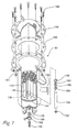
- separator 80 has an inlet port 138 and an overflow outlet 140.
- the length of cyclones 134 can extend from below vessel inlet 138 to a region adjacent to overflow outlet 140.
- Cyclones I34 can be secured to an upper plate 142 and a lower plate 144.
- each cyclone 134 contacts upper plate 142 and forms a seal, to minimize leakage of the inlet stream entering port 138 (a reduced particulate stream) into the overflow stream exiting port 140.
- a seal that holds an individual cyclone to its manifold allows the system to be sufficiently robust to withstand thermal effects (e.g. contraction and expansion) and prevents unwanted entry and/or mixing of a reduced particulate overflow stream with the subsequent reduced particulate stream.
- thermal effects e.g. contraction and expansion
- such seals can be affected by extreme swings in temperature.
- a flash zone gas oil stream can be fed to a cyclonic separator at a temperature between about 600°F (315.6°C) to about 800°F (426.7°C) during operation.
- the cyclonic units may be at much lower ambient temperatures of about 50°F (10°C) to 60°F (15.6°C), or even less, depending on the climate.
- the present invention has overcome these challenges by implementing a seal that can maintain its seal capability and integrity even through multiple cycles between broad temperature ranges, such as from ambient to 800°F (426.7 °C), and back.
- each cyclone 134 preferablycontacts a lower plate 144 with a gasket 156, and contacts an upper plate 142 by a bushing 158, washer 160, gasket 162 and a spring washer 164.
- the assembly comprises at least two spring washers.
- a preferred spring washer is a Bellville or disc washer.
- Suitable materials for gaskets 156 and 162 comprise material that remains flexible at high temperatures (e.g. above 600°F (315.6°C).
- a preferred material is flexible graphite.
- Apex 146 can be secured to vessel body 136 with an adjustable clamp 166, a centering ring 168, and a gasket 170.
- apex 146 is removable.
- apex 146 can be non-removable and coupled to vessel body 136 using a flange-style connection.
- the manifold of cyclones can optionally include elongate rods that connect the top and bottom plates, 142 and 144, respectively, to provide stiffening support to the manifold.
- the rods minimize potential movement of the vessel plates during thermal changes that occur during operation of the process.
- an inspection/drain conduit can be provided to allow drainage of the fluid level. This is particularly useful when a unit has to be shutdown for maintenance activities.
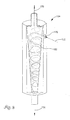
- FIG. 8 depicts an individual cyclone 134 suitable for configuration into a cyclonic separator 80.
- This figure is provided merely to illustrate the fluid flow within a cyclone, where a FZGO stream (illustrated by dashed line) 172 is separated into an underflow stream 174 containing displaced particulate material, and a reduced particulate overflow stream 176, the stream having been substantially stripped of particulate material.
- the FZGO stream enters tangentially into cyclone 134 through an inlet or nozzle 178 and forms a whirlpool or vortex effect.
- the particulate solid material (not shown) generally having a higher density (i.e.
Landscapes
- Chemical & Material Sciences (AREA)
- Oil, Petroleum & Natural Gas (AREA)
- Engineering & Computer Science (AREA)
- Chemical Kinetics & Catalysis (AREA)
- Organic Chemistry (AREA)
- General Chemical & Material Sciences (AREA)
- Thermal Sciences (AREA)
- Physics & Mathematics (AREA)
- Materials Engineering (AREA)
- Cyclones (AREA)
- Production Of Liquid Hydrocarbon Mixture For Refining Petroleum (AREA)
- Separating Particles In Gases By Inertia (AREA)
- Catalysts (AREA)
Applications Claiming Priority (2)
| Application Number | Priority Date | Filing Date | Title |
|---|---|---|---|
| US10/121,897 US6919017B2 (en) | 2002-04-11 | 2002-04-11 | Separation process and apparatus for removal of particulate material from flash zone gas oil |
| EP03728375A EP1495089A1 (en) | 2002-04-11 | 2003-04-10 | Separation process and apparatus for removal of particulate material from delayed coking gas oil |
Related Parent Applications (1)
| Application Number | Title | Priority Date | Filing Date |
|---|---|---|---|
| EP03728375A Division EP1495089A1 (en) | 2002-04-11 | 2003-04-10 | Separation process and apparatus for removal of particulate material from delayed coking gas oil |
Publications (1)
| Publication Number | Publication Date |
|---|---|
| EP1970426A1 true EP1970426A1 (en) | 2008-09-17 |
Family
ID=28790434
Family Applications (2)
| Application Number | Title | Priority Date | Filing Date |
|---|---|---|---|
| EP03728375A Withdrawn EP1495089A1 (en) | 2002-04-11 | 2003-04-10 | Separation process and apparatus for removal of particulate material from delayed coking gas oil |
| EP08006501A Withdrawn EP1970426A1 (en) | 2002-04-11 | 2003-04-10 | Separation process and apparatus for removal of particulate material from delayed coking gas oil |
Family Applications Before (1)
| Application Number | Title | Priority Date | Filing Date |
|---|---|---|---|
| EP03728375A Withdrawn EP1495089A1 (en) | 2002-04-11 | 2003-04-10 | Separation process and apparatus for removal of particulate material from delayed coking gas oil |
Country Status (18)
| Country | Link |
|---|---|
| US (2) | US6919017B2 (zh) |
| EP (2) | EP1495089A1 (zh) |
| JP (1) | JP4417726B2 (zh) |
| KR (1) | KR100964418B1 (zh) |
| CN (1) | CN1266253C (zh) |
| AR (1) | AR039407A1 (zh) |
| AU (1) | AU2003234719B2 (zh) |
| BR (3) | BR122012025977B1 (zh) |
| CA (1) | CA2479092C (zh) |
| EA (1) | EA006143B1 (zh) |
| EG (1) | EG23435A (zh) |
| MX (1) | MXPA04009812A (zh) |
| MY (1) | MY132765A (zh) |
| NO (1) | NO342768B1 (zh) |
| TW (1) | TWI256972B (zh) |
| UA (1) | UA78778C2 (zh) |
| WO (1) | WO2003087267A1 (zh) |
| ZA (1) | ZA200407504B (zh) |
Families Citing this family (15)
| Publication number | Priority date | Publication date | Assignee | Title |
|---|---|---|---|---|
| US7720641B2 (en) * | 2006-04-21 | 2010-05-18 | Exxonmobil Research And Engineering Company | Application of abnormal event detection technology to delayed coking unit |
| US7875103B2 (en) * | 2006-04-26 | 2011-01-25 | Mueller Environmental Designs, Inc. | Sub-micron viscous impingement particle collection and hydraulic removal system |
| US20080120060A1 (en) * | 2006-09-29 | 2008-05-22 | Fisher-Rosemount Systems, Inc. | Detection of catalyst losses in a fluid catalytic cracker for use in abnormal situation prevention |
| US9222044B2 (en) | 2010-07-26 | 2015-12-29 | Uop Llc | Methods for producing low oxygen biomass-derived pyrolysis oils |
| US8940067B2 (en) | 2011-09-30 | 2015-01-27 | Mueller Environmental Designs, Inc. | Swirl helical elements for a viscous impingement particle collection and hydraulic removal system |
| US9187696B2 (en) * | 2013-03-14 | 2015-11-17 | Bechtel Hydrocarbon Technology Solutions, Inc. | Delayed coking drum quench overflow systems and methods |
| PL2970046T3 (pl) * | 2013-03-15 | 2019-07-31 | Bechtel Hydrocarbon Technology Solutions, Inc. | Układy i sposoby zewnętrznego przetwarzania oleju gazowego ze strefy zapłonu ze sposobu opóźnionego koksowania |
| WO2015041935A1 (en) * | 2013-09-18 | 2015-03-26 | Shell Oil Company | Methods and systems for supplying hydrogen to a hydrocatalytic reaction |
| EP3083035A1 (en) | 2013-12-20 | 2016-10-26 | Shell Internationale Research Maatschappij B.V. | Methods and systems for processing a reaction product mixture of a cellulosic biomass material |
| BR112018005408B8 (pt) * | 2015-09-21 | 2022-08-02 | Bechtel Hydrocarbon Technology Solutions Inc | Sistema e método para reduzir emissões atmosféricas de vapores de hidrocarboneto |
| CN105233602B (zh) * | 2015-10-12 | 2017-09-22 | 西安交通大学 | 用于粉煤低温干馏中高温焦油气与细粉尘颗粒分离的系统 |
| US10711589B2 (en) | 2018-08-08 | 2020-07-14 | A.S.A.P. Industries Manufacturing, Inc. | Sand separator |
| CN109628135B (zh) * | 2018-12-10 | 2024-01-30 | 西北大学 | 一种生焦装置及使用方法 |
| US11932816B2 (en) | 2019-02-15 | 2024-03-19 | Exxonmobil Chemical Patents Inc. | Coke and tar removal from a furnace effluent |
| US11852258B2 (en) * | 2020-12-31 | 2023-12-26 | Tapcoenpro, Llc | Systems and methods for purging an isolation valve with a liquid purge medium |
Citations (5)
| Publication number | Priority date | Publication date | Assignee | Title |
|---|---|---|---|---|
| EP0156614A2 (en) * | 1984-03-20 | 1985-10-02 | Gulf Canada Resources Limited | Coking residuum in the presence of hydrogen donor |
| US4882036A (en) * | 1987-09-16 | 1989-11-21 | Exxon Research And Engineering Company | Combination coking and hydroconversion process |
| US5059301A (en) * | 1988-11-29 | 1991-10-22 | Conoco | Process for the preparation of recarburizer coke |
| US5645712A (en) * | 1996-03-20 | 1997-07-08 | Conoco Inc. | Method for increasing yield of liquid products in a delayed coking process |
| US5824194A (en) * | 1997-01-07 | 1998-10-20 | Bechtel Corporation | Fractionator system for delayed coking process |
Family Cites Families (10)
| Publication number | Priority date | Publication date | Assignee | Title |
|---|---|---|---|---|
| DE2622880C3 (de) * | 1976-05-21 | 1981-05-14 | Amberger Kaolinwerke Gmbh, 8452 Hirschau | Verfahren zum fraktionierten von suspendierten Feststoffen mittels Hydrozyklonen, sowie Anordnung zur Durchführung des Verfahrens |
| US4354920A (en) * | 1976-12-27 | 1982-10-19 | Chevron Research Company | Coal liquefaction process |
| SE403441B (sv) * | 1977-01-05 | 1978-08-21 | Skardal Karl Arvid | Virvelrenare med i dess avsmalnande del axiellt anordnade och i direkt forbindelse med varandra staende kammaravsnitt |
| US4208270A (en) | 1978-03-27 | 1980-06-17 | Krebs Engineers | Hydrocyclone assembly |
| DE3609988C2 (de) * | 1986-03-25 | 1994-08-04 | Metallgesellschaft Ag | Kombiniertes Verfahren zum Abtrennen und Behandeln von Asphaltenen mit hoher Erweichungstemperatur |
| CA1312033C (en) * | 1987-09-16 | 1992-12-29 | Clarence M. Eidt, Jr. | Combination coking and hydroconversion process |
| FR2716458B1 (fr) | 1994-02-22 | 1996-04-12 | Inst Francais Du Petrole | Procédé et dispositif de décokage. |
| US5645711A (en) * | 1996-01-05 | 1997-07-08 | Conoco Inc. | Process for upgrading the flash zone gas oil stream from a delayed coker |
| US6129217A (en) | 1996-03-29 | 2000-10-10 | Corn Products International, Inc. | Hydrocyclone and separator assemblies utilizing hydrocyclones |
| US5954949A (en) * | 1998-03-25 | 1999-09-21 | Unipure Corporation | Conversion of heavy petroleum oils to coke with a molten alkali metal hydroxide |
-
2002
- 2002-04-11 US US10/121,897 patent/US6919017B2/en not_active Expired - Lifetime
-
2003
- 2003-04-09 EG EG2003040333A patent/EG23435A/xx active
- 2003-04-10 KR KR1020047015063A patent/KR100964418B1/ko active IP Right Grant
- 2003-04-10 CN CNB038079895A patent/CN1266253C/zh not_active Expired - Fee Related
- 2003-04-10 BR BRBR122012025977-2A patent/BR122012025977B1/pt not_active IP Right Cessation
- 2003-04-10 BR BRPI0308822A patent/BRPI0308822C8/pt unknown
- 2003-04-10 CA CA2479092A patent/CA2479092C/en not_active Expired - Fee Related
- 2003-04-10 MX MXPA04009812A patent/MXPA04009812A/es active IP Right Grant
- 2003-04-10 MY MYPI20031334A patent/MY132765A/en unknown
- 2003-04-10 EP EP03728375A patent/EP1495089A1/en not_active Withdrawn
- 2003-04-10 JP JP2003584211A patent/JP4417726B2/ja not_active Expired - Fee Related
- 2003-04-10 WO PCT/US2003/011245 patent/WO2003087267A1/en active Application Filing
- 2003-04-10 EA EA200401351A patent/EA006143B1/ru not_active IP Right Cessation
- 2003-04-10 BR BR0308822-7A patent/BR0308822A/pt not_active IP Right Cessation
- 2003-04-10 AU AU2003234719A patent/AU2003234719B2/en not_active Ceased
- 2003-04-10 EP EP08006501A patent/EP1970426A1/en not_active Withdrawn
- 2003-04-11 AR ARP030101278A patent/AR039407A1/es active IP Right Grant
- 2003-04-11 TW TW092108393A patent/TWI256972B/zh not_active IP Right Cessation
- 2003-10-04 UA UA20041109197A patent/UA78778C2/uk unknown
-
2004
- 2004-09-17 ZA ZA2004/07504A patent/ZA200407504B/en unknown
- 2004-10-19 NO NO20044443A patent/NO342768B1/no not_active IP Right Cessation
-
2005
- 2005-03-21 US US11/086,950 patent/US7476295B2/en not_active Expired - Fee Related
Patent Citations (5)
| Publication number | Priority date | Publication date | Assignee | Title |
|---|---|---|---|---|
| EP0156614A2 (en) * | 1984-03-20 | 1985-10-02 | Gulf Canada Resources Limited | Coking residuum in the presence of hydrogen donor |
| US4882036A (en) * | 1987-09-16 | 1989-11-21 | Exxon Research And Engineering Company | Combination coking and hydroconversion process |
| US5059301A (en) * | 1988-11-29 | 1991-10-22 | Conoco | Process for the preparation of recarburizer coke |
| US5645712A (en) * | 1996-03-20 | 1997-07-08 | Conoco Inc. | Method for increasing yield of liquid products in a delayed coking process |
| US5824194A (en) * | 1997-01-07 | 1998-10-20 | Bechtel Corporation | Fractionator system for delayed coking process |
Non-Patent Citations (1)
| Title |
|---|
| KIRK-OTHMER: "Encyclopedia of chemical technology"", 1996, JOHN WILEY & SONS, NEW YORK, XP002245352 * |
Also Published As
| Publication number | Publication date |
|---|---|
| US6919017B2 (en) | 2005-07-19 |
| EP1495089A1 (en) | 2005-01-12 |
| CN1646663A (zh) | 2005-07-27 |
| AU2003234719B2 (en) | 2008-10-23 |
| TW200307035A (en) | 2003-12-01 |
| EA006143B1 (ru) | 2005-10-27 |
| EA200401351A1 (ru) | 2005-04-28 |
| US7476295B2 (en) | 2009-01-13 |
| WO2003087267A1 (en) | 2003-10-23 |
| NO20044443L (no) | 2004-10-19 |
| MXPA04009812A (es) | 2004-12-13 |
| AU2003234719A1 (en) | 2003-10-27 |
| BRPI0308822B1 (pt) | 2019-05-07 |
| MY132765A (en) | 2007-10-31 |
| BR122012025977B1 (pt) | 2015-08-04 |
| NO342768B1 (no) | 2018-08-06 |
| AR039407A1 (es) | 2005-02-16 |
| ZA200407504B (en) | 2005-12-28 |
| CA2479092C (en) | 2010-04-20 |
| CA2479092A1 (en) | 2003-10-23 |
| CN1266253C (zh) | 2006-07-26 |
| US20050194290A1 (en) | 2005-09-08 |
| BR0308822A (pt) | 2005-01-04 |
| KR100964418B1 (ko) | 2010-06-16 |
| KR20040106304A (ko) | 2004-12-17 |
| JP2005532420A (ja) | 2005-10-27 |
| EG23435A (en) | 2005-08-22 |
| BRPI0308822B8 (pt) | 2019-05-28 |
| UA78778C2 (en) | 2007-04-25 |
| US20030192810A1 (en) | 2003-10-16 |
| BRPI0308822C8 (pt) | 2019-06-25 |
| JP4417726B2 (ja) | 2010-02-17 |
| TWI256972B (en) | 2006-06-21 |
Similar Documents
| Publication | Publication Date | Title |
|---|---|---|
| US7476295B2 (en) | Separation apparatus for removal of particulate material from flash zone gas oil | |
| US5308586A (en) | Electrostatic separator using a bead bed | |
| US6797026B2 (en) | Apparatus and process for separating fine solid particulates from a gas stream | |
| CA2437651C (en) | Catalyst recovery from light olefin fcc effluent | |
| US7547427B2 (en) | Multiple stage separator vessel | |
| CN101445744B (zh) | 脱除原料油中焦粉的方法及装置 | |
| US6110356A (en) | Slurry circulation process and system for fluidized particle contacting | |
| US20150005553A1 (en) | Dual Riser Vortex Separation System | |
| US8932452B2 (en) | Method for separating entrained catalyst and catalyst fines from slurry oil | |
| CN102232008B (zh) | 处理具有不同液体流速和固体含量的浆料的方法和系统 | |
| US5770078A (en) | Phase separator apparatus to separate a mixture of liquids and finely divided suspended particles | |
| US5599463A (en) | Phase separator apparatus and its use to separate a mixture of liquids and finely divided suspended particles | |
| US4022675A (en) | Filtering process | |
| WO2010014385A2 (en) | Process and apparatus for separating solids from gas | |
| CN109423330A (zh) | 一种催化裂化油浆的处理方法 | |
| GB2030468A (en) | Separating suspended solids from a liquid containing them | |
| CN101811785A (zh) | 延迟焦化放空水旋流除焦的方法与装置 | |
| AU2002342812A1 (en) | Process to separate solids from a solids laden gaseous feed stream |
Legal Events
| Date | Code | Title | Description |
|---|---|---|---|
| PUAI | Public reference made under article 153(3) epc to a published international application that has entered the european phase |
Free format text: ORIGINAL CODE: 0009012 |
|
| AC | Divisional application: reference to earlier application |
Ref document number: 1495089 Country of ref document: EP Kind code of ref document: P |
|
| AK | Designated contracting states |
Kind code of ref document: A1 Designated state(s): AT BE BG CH CY CZ DE DK EE ES FI FR GB GR HU IE IT LI LU MC NL PT RO SE SI SK TR |
|
| 17P | Request for examination filed |
Effective date: 20090313 |
|
| AKX | Designation fees paid |
Designated state(s): AT BE BG CH CY CZ DE DK EE ES FI FR GB GR HU IE IT LI LU MC NL PT RO SE SI SK TR |
|
| 17Q | First examination report despatched |
Effective date: 20090427 |
|
| STAA | Information on the status of an ep patent application or granted ep patent |
Free format text: STATUS: THE APPLICATION IS DEEMED TO BE WITHDRAWN |
|
| 18D | Application deemed to be withdrawn |
Effective date: 20091110 |