EP1970115A2 - CO2 recovery system and waste-product removing method - Google Patents
CO2 recovery system and waste-product removing method Download PDFInfo
- Publication number
- EP1970115A2 EP1970115A2 EP07119774A EP07119774A EP1970115A2 EP 1970115 A2 EP1970115 A2 EP 1970115A2 EP 07119774 A EP07119774 A EP 07119774A EP 07119774 A EP07119774 A EP 07119774A EP 1970115 A2 EP1970115 A2 EP 1970115A2
- Authority
- EP
- European Patent Office
- Prior art keywords
- product
- solution
- condensed waste
- lean solution
- recovery system
- Prior art date
- Legal status (The legal status is an assumption and is not a legal conclusion. Google has not performed a legal analysis and makes no representation as to the accuracy of the status listed.)
- Granted
Links
Images

Classifications
-
- B—PERFORMING OPERATIONS; TRANSPORTING
- B01—PHYSICAL OR CHEMICAL PROCESSES OR APPARATUS IN GENERAL
- B01D—SEPARATION
- B01D53/00—Separation of gases or vapours; Recovering vapours of volatile solvents from gases; Chemical or biological purification of waste gases, e.g. engine exhaust gases, smoke, fumes, flue gases, aerosols
- B01D53/14—Separation of gases or vapours; Recovering vapours of volatile solvents from gases; Chemical or biological purification of waste gases, e.g. engine exhaust gases, smoke, fumes, flue gases, aerosols by absorption
- B01D53/1425—Regeneration of liquid absorbents
-
- B—PERFORMING OPERATIONS; TRANSPORTING
- B01—PHYSICAL OR CHEMICAL PROCESSES OR APPARATUS IN GENERAL
- B01D—SEPARATION
- B01D53/00—Separation of gases or vapours; Recovering vapours of volatile solvents from gases; Chemical or biological purification of waste gases, e.g. engine exhaust gases, smoke, fumes, flue gases, aerosols
- B01D53/14—Separation of gases or vapours; Recovering vapours of volatile solvents from gases; Chemical or biological purification of waste gases, e.g. engine exhaust gases, smoke, fumes, flue gases, aerosols by absorption
- B01D53/1456—Removing acid components
- B01D53/1475—Removing carbon dioxide
-
- C—CHEMISTRY; METALLURGY
- C01—INORGANIC CHEMISTRY
- C01B—NON-METALLIC ELEMENTS; COMPOUNDS THEREOF; METALLOIDS OR COMPOUNDS THEREOF NOT COVERED BY SUBCLASS C01C
- C01B32/00—Carbon; Compounds thereof
- C01B32/50—Carbon dioxide
-
- Y—GENERAL TAGGING OF NEW TECHNOLOGICAL DEVELOPMENTS; GENERAL TAGGING OF CROSS-SECTIONAL TECHNOLOGIES SPANNING OVER SEVERAL SECTIONS OF THE IPC; TECHNICAL SUBJECTS COVERED BY FORMER USPC CROSS-REFERENCE ART COLLECTIONS [XRACs] AND DIGESTS
- Y02—TECHNOLOGIES OR APPLICATIONS FOR MITIGATION OR ADAPTATION AGAINST CLIMATE CHANGE
- Y02C—CAPTURE, STORAGE, SEQUESTRATION OR DISPOSAL OF GREENHOUSE GASES [GHG]
- Y02C20/00—Capture or disposal of greenhouse gases
- Y02C20/40—Capture or disposal of greenhouse gases of CO2
-
- Y—GENERAL TAGGING OF NEW TECHNOLOGICAL DEVELOPMENTS; GENERAL TAGGING OF CROSS-SECTIONAL TECHNOLOGIES SPANNING OVER SEVERAL SECTIONS OF THE IPC; TECHNICAL SUBJECTS COVERED BY FORMER USPC CROSS-REFERENCE ART COLLECTIONS [XRACs] AND DIGESTS
- Y02—TECHNOLOGIES OR APPLICATIONS FOR MITIGATION OR ADAPTATION AGAINST CLIMATE CHANGE
- Y02P—CLIMATE CHANGE MITIGATION TECHNOLOGIES IN THE PRODUCTION OR PROCESSING OF GOODS
- Y02P20/00—Technologies relating to chemical industry
- Y02P20/151—Reduction of greenhouse gas [GHG] emissions, e.g. CO2
Definitions
- the present invention relates to a CO 2 recovery system and a method of removing a depleted material, which is produced in the CO 2 recovery system, from a reclaimer in a short period.
- CO 2 emitted into the atmosphere has been considered as the prime cause of the greenhouse effect.
- CO 2 sources range various fields of human activities, including burning of fossil fuels, and demands to suppress CO 2 emission from these sources are constantly increasing.
- scientists have energetically studied means and methods for suppressing the emission of CO 2 from power generation facilities such as power generation stations which use an enormous amount of fossil fuels.
- One of the methods includes bringing combustion exhaust gas of boilers into contact with an amine-based CO 2 -absorbing solution. This method allows the removal and recovery of CO 2 from the combustion exhaust gas.
- Another method includes storing recovered CO 2 , i.e., not returning the recovered CO 2 to the atmosphere.
- Japanese Patent Application Laid-Open No. H5-245339 discloses a method of contacting the combustion exhaust gas with the CO 2 -absorbing solution in an absorption tower, heating an absorbing solution having absorbed CO 2 in a regeneration tower, and releasing CO 2 , regenerating the absorbing solution, and circulating the regenerated absorbing solution to the absorption tower again to be reused.
- CO 2 - containing exhaust gas 1002 discharged from a factory 1001 is cooled with coolant water 1003 in a cooling tower 1004.
- the factory 1001 can be a boiler.
- the cooled CO 2 -containing exhaust gas 1002 is then conveyed to an absorption tower 1006 where it is brought into countercurrent contact with CO 2 -absorbing solution 1005.
- the CO 2 -absorbing solution 1005 can be an alkanolamine-based solution.
- CO 2 in the CO 2 -containing exhaust gas 1002 is absorbed into the CO 2 -absorbing solution 1005, that is, CO 2 is removed from the CO 2 -containing exhaust gas 1002.
- the CO 2 -absorbing solution 1005 containing CO 2 (hereinafter, "rich solution 1007") is conveyed to a regeneration tower 1008.
- the rich solution 1007 drips downward in the regeneration tower 1008.
- the rich solution 1007 reaches a lower portion of the regeneration tower 1008, most of the CO 2 absorbed in the rich solution 1007 is released, and the rich solution 1007 turns into lean solution 1009 capable of working as the CO 2 -absorbing solution 1005.
- the lean solution 1009 is returned to the absorption tower 1006 and it is reused as the CO 2 -absorbing solution 1005.
- thermostable salt mixes with the lean solution 1009, which creates various issues.
- the thermostable salt cannot be removed under normal conditions in a course of producing the lean solution 1009 from the rich solution 1007, so that the thermostable salt accumulates in the system while the lean solution 1009 circulates.
- the CO 2 recovery system 1000 includes a reclaimer 1040 to which the lean solution 1009 that is produced in the regeneration tower 1008 is supplied.
- the reclaimer 1040 heats the lean solution 1009 to produce a condensed depleted material such as a salt. The condensed depleted material is then removed.
- the lean solution 1009 passing through a lean-solution supply line 1022 is extracted through an extracting line 1041 that is stretched from the lean-solution supply line 1022 to the reclaimer 1040, and the depleted material is removed from the extracted lean solution 1009 in the reclaimer 1040.
- the lean solution 1009 is heated in the reclaimer 1040 to, for example, 130°C to 150°C, so that CO 2 -absorbing solution is vaporized from the lean solution 1009.
- a vaporized CO 2 -absorbing solution 1047 is supplied to the lower portion of the regeneration tower 1008.
- a condensed waste-product 1042 accumulated on a bottom of the reclaimer 1040 is removed, for example, by pumping with a pump.
- a reclaimer with higher capacity for accumulating condensed waste-product is required for a CO 2 recovery system having a higher capacity to remove CO 2 .
- the capacity of the CO 2 recovery system 1000 is to recover 1,000 tons to 3,000 tons of CO 2 per day, 30 m 3 to 100 m 3 of the condensed waste-product 1042 accumulates in the reclaimer 1040.
- the depleted material that is being cooled-down adheres to a steam supply line 1050 for supplying saturated steam 1046, so that the steam supply line 1050 needs to be periodically detached for cleaning.
- a CO 2 recovery system including an absorption tower that receives CO 2 -containing gas and CO 2 -absorbing solution, and causes the CO 2 -containing gas to come in contact with the CO 2 -absorbing solution to produce CO 2 rich solution, and a regeneration tower that receives the rich solution and produces lean solution from the rich solution by removing CO 2 from the rich solution.
- the CO 2 recovery system includes a heating unit that receives the lean solution produced in the regeneration tower and heats the lean solution to obtain condensed waste-product from the lean solution; and a cooling unit that receives the condensed waste-product from the heating unit and cools the condensed waste-product.
- a method of removing waste-product in a CO 2 recovery system including an absorption tower that receives CO 2 -containing gas and CO 2 -absorbing solution, and causes the CO 2 -containing gas to come in contact with the CO 2 -absorbing solution to produce CO 2 rich solution, and a regeneration tower that receives the rich solution and produces lean solution from the rich solution by removing CO 2 from the rich solution.
- the method includes taking out the lean solution produced in the regeneration tower and heating the lean solution to obtain condensed waste-product from the lean solution; and taking out the condensed waste-product and cooling the condensed waste-product.
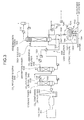
- Fig. 1 is a schematic diagram of a CO 2 recovery system 100 according to an embodiment of the present invention
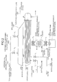
- Fig. 2 is an enlarged schematic diagram of the reclaimer 1040 and relevant parts shown in Fig. 1 .
- the same components as those of the conventional CO 2 recovery system shown in Fig. 3 are assigned with the same reference numerals, and explanation thereof is omitted.
- the CO 2 recovery system 100 includes the absorption tower 1006, the regeneration tower 1008, the reclaimer 1040, and a cooler 101.
- the absorption tower 1006 receives the CO 2 -containing exhaust gas 1002 and the CO 2 -absorbing solution 1005, and causes the CO 2 -containing exhaust gas 1002 to come in contact with the CO 2 -absorbing solution 1005 to produce the rich solution 1007.
- the regeneration tower 1008 receives the rich solution 1007 and produces the lean solution 1009 from the rich solution 1007 by removing CO 2 from the rich solution 1007.
- the reclaimer 1040 receives the lean solution 1009 that is produced in the regeneration tower 1008 and heats the lean solution 1009 to produce a condensed waste-product 1042H by condensing a depleted material contained in the lean solution 1009.
- the cooler 101 receives the high-temperature condensed waste-product 1042H and cools the condensed waste-product 1042H to produce a low-temperature condensed waste-product 1042L.
- a receiving tank 102 is provided below the cooler 101.
- the receiving tank 102 receives the condensed waste-product 1042L from the cooler 101.
- a valve V 1 controls flow of the lean solution 1009 in the extracting line 1041 to the reclaimer 1040.
- a valve V 2 controls flow of water 1043 in a water supply line 1044 to the reclaimer 1040.
- a valve V 3 controls flow of the vaporized CO 2 -absorbing solution 1047, which is produced in the reclaimer 1040, in a vaporized CO 2 -absorbing solution supply line 1048 to a lower portion of the regeneration tower 1008.
- a valve V 4 controls flow of the condensed waste-product 1042H, which is at a high temperature, from the reclaimer 1040 to the cooler 101.
- a valve V 5 controls flow of the condensed waste-product 1042L, which is at a low temperature, from the cooler 101 to the receiving tank 102.
- the condensed waste-product 1042H or 1042L is the material obtained by heating the lean solution 1009 including a depleted material such as a salt.
- the depleted material is produced from the amine-based absorbing solution due to a chemical reaction that occurs when CO 2 is separated from the CO2-containing exhaust gas 1002 in the absorption tower 1006.
- the lean solution 1009 flows to the reclaimer 1040 via the extracting line 1041.
- the water 1043 flows to the reclaimer 1040 via the water supply line 1044.
- the saturated steam 1046 is supplied to the reclaimer 1040 via a saturated-steam supply line 1045, the lean solution 1009 and the water 1043 in the reclaimer 1040 get heated by the saturated steam 1046 so that the vaporized CO 2 -absorbing solution 1047 is produced.
- the vaporized CO 2 -absorbing solution supply line 1048 has two of the valves V 3 at different positions.
- both the valves V 3 When both the valves V 3 are open, the vaporized CO 2 -absorbing solution 1047 flows to the lower portion of the regeneration tower 1008 via the vaporized CO 2 -absorbing solution supply line 1048.
- both of the valve V 4 arranged between the reclaimer 1040 and the cooler 101 and the valve V 5 arranged below the cooler 101 are closed.
- the cooler 101 is located below the reclaimer 1040. When a predetermined amount of the condensed waste-product 1042H is produced in the reclaimer 1040, a portion of the condensed waste-product 1042H is conveyed to the cooler 101. The cooler 101 cools that portion of the condensed waste-product 1042H.
- the lean solution 1009 and the water 1043 are heated in the reclaimer 1040 to produce the high-temperature condensed waste-product 1042H by condensing the depleted material in the lean solution 1009. Then, the valve V 4 is open whereby the condensed waste-product 1042H is conveyed to the cooler 101. When the valve V 4 is open state, the valve V 5 is closed. After a portion of the condensed waste-product 1042H is conveyed to the cooler 101, the valve V 4 is closed.
- the amount of the portion of the condensed waste-product 1042H that is conveyed at one time is small, for example, 0.2 m 3 to 3 m 3 .
- the high-temperature condensed waste-product 1042H is cooled in the cooler 101 to a temperature of about 50°C or less. This cooling produces the low-temperature condensed waste-product 1042L.
- the condensed waste-product 1042L is then conveyed from the cooler 101 to the receiving tank 102, while the valve V 5 is opened and the valve V 4 is closed.
- the low-temperature condensed waste-product 1042L is conveyed to a processing tank (not shown) by a tank truck (tanker lorry) (not shown) or the like, or temporarily stored in a storage tank (not shown).
- the reclaimer 1040 During the cooling process, because the reclaimer 1040 always contains therein the high-temperature condensed waste-product 1042H, the reclaimer 1040 is always maintained in hot state. As a result, the depleted material, such as a salt contained in the lean solution 1009, does not adhere to the steam supply line 1050. It means that the steam supply line 1050 need not be detached for cleaning.
- the condensed waste-product 1042H is hot while it is in the reclaimer 1040, even if a reclaimer has a large capacity in which a large amount of condensed waste-product can be accumulated, the condensed waste-product can be removed from such a reclaimer in a shorter period. It means that, when a large amount of high-temperature condensed waste-product, for example 30 m 3 or larger, accumulates in the large reclaimer as a result of recovery of a large amount of CO 2 , for example 1000 tons or larger, the CO 2 recovery system 100 can process the large amount of the high-temperature condensed waste-product in a shorter period.
- a small portion of condensed waste-product is transported in hot state from a reclaimer to a cooler and cooled, and this process is repeated for the whole condensed waste-product. Because only a small portion is processed each time, the condensed waste-product can be removed from the reclaimer in a shorter period.
Landscapes
- Chemical & Material Sciences (AREA)
- Chemical Kinetics & Catalysis (AREA)
- Engineering & Computer Science (AREA)
- Analytical Chemistry (AREA)
- General Chemical & Material Sciences (AREA)
- Oil, Petroleum & Natural Gas (AREA)
- Organic Chemistry (AREA)
- Inorganic Chemistry (AREA)
- Gas Separation By Absorption (AREA)
- Treating Waste Gases (AREA)
Abstract
Description
- The present invention relates to a CO2 recovery system and a method of removing a depleted material, which is produced in the CO2 recovery system, from a reclaimer in a short period.
- In recent years the greenhouse effect has been pointed out as one of the causes of global warming, and a countermeasure against it is urgently required internationally to protect global environment. CO2 emitted into the atmosphere has been considered as the prime cause of the greenhouse effect. CO2 sources range various fields of human activities, including burning of fossil fuels, and demands to suppress CO2 emission from these sources are constantly increasing. Scientists have energetically studied means and methods for suppressing the emission of CO2 from power generation facilities such as power generation stations which use an enormous amount of fossil fuels. One of the methods includes bringing combustion exhaust gas of boilers into contact with an amine-based CO2-absorbing solution. This method allows the removal and recovery of CO2 from the combustion exhaust gas. Another method includes storing recovered CO2, i.e., not returning the recovered CO2 to the atmosphere.
- Various methods are known to remove and recover CO2 from combustion exhaust gas using the CO2-absorbing solution. Japanese Patent Application Laid-Open No.
H5-245339 - As shown in
Fig. 3 , in a conventional CO2 recovery system 1000, CO2- containingexhaust gas 1002 discharged from afactory 1001 is cooled withcoolant water 1003 in acooling tower 1004. Thefactory 1001 can be a boiler. The cooled CO2-containing exhaust gas 1002 is then conveyed to anabsorption tower 1006 where it is brought into countercurrent contact with CO2-absorbing solution 1005. The CO2-absorbing solution 1005 can be an alkanolamine-based solution. CO2 in the CO2-containing exhaust gas 1002 is absorbed into the CO2-absorbing solution 1005, that is, CO2 is removed from the CO2-containing exhaust gas 1002. The CO2-absorbing solution 1005 containing CO2 (hereinafter, "rich solution 1007") is conveyed to aregeneration tower 1008. Therich solution 1007 drips downward in theregeneration tower 1008. When therich solution 1007 reaches a lower portion of theregeneration tower 1008, most of the CO2 absorbed in therich solution 1007 is released, and therich solution 1007 turns intolean solution 1009 capable of working as the CO2-absorbing solution 1005. Thelean solution 1009 is returned to theabsorption tower 1006 and it is reused as the CO2-absorbing solution 1005. - In the CO2 recovery system 1000, material such as a sulfur oxide (SOx) remains un-removed in a desulphurization step. Such residual material reacts with alkanolamine contained in the CO2-absorbing solution 1005 in the CO2-removing process or an amine is oxidized in a process of recovering CO2 from the exhaust gas thereby producing a thermostable salt. The thermostable salt mixes with the
lean solution 1009, which creates various issues. The thermostable salt cannot be removed under normal conditions in a course of producing thelean solution 1009 from therich solution 1007, so that the thermostable salt accumulates in the system while thelean solution 1009 circulates. - The CO2 recovery system 1000 includes a
reclaimer 1040 to which thelean solution 1009 that is produced in theregeneration tower 1008 is supplied. Thereclaimer 1040 heats thelean solution 1009 to produce a condensed depleted material such as a salt. The condensed depleted material is then removed. - More particularly, the
lean solution 1009 passing through a lean-solution supply line 1022 is extracted through an extractingline 1041 that is stretched from the lean-solution supply line 1022 to thereclaimer 1040, and the depleted material is removed from the extractedlean solution 1009 in thereclaimer 1040. Thelean solution 1009 is heated in thereclaimer 1040 to, for example, 130°C to 150°C, so that CO2-absorbing solution is vaporized from thelean solution 1009. A vaporized CO2-absorbing solution 1047 is supplied to the lower portion of theregeneration tower 1008. A condensed waste-product 1042 accumulated on a bottom of thereclaimer 1040 is removed, for example, by pumping with a pump. - Assuming that the capacity of the CO2 recovery system 1000 to recover CO2 is about 300 tons per day, about 10 m3 of the condensed waste-
product 1042 accumulates in thereclaimer 1040. A cooling period of one to two weeks is required for the condensed waste-product 1042 to cool-down before it can be removed. - A reclaimer with higher capacity for accumulating condensed waste-product is required for a CO2 recovery system having a higher capacity to remove CO2. For example, if the capacity of the CO2 recovery system 1000 is to recover 1,000 tons to 3,000 tons of CO2 per day, 30 m3 to 100 m3 of the condensed waste-
product 1042 accumulates in thereclaimer 1040. - In the large-capacity CO2 recovery system, which employs the natural-cooling method, a longer cool-down period is required. It may take one month or longer for the cooling-down period in a near feature. There is a need for shortening the period for which the condensed waste-product stays in the reclaimer.
- In addition, in the case of the natural-cooling method, the depleted material that is being cooled-down adheres to a
steam supply line 1050 for supplyingsaturated steam 1046, so that thesteam supply line 1050 needs to be periodically detached for cleaning. - It is an object of the present invention to at least partially solve the problems in the conventional technology.
- According to an aspect of the present invention, there is provided a CO2 recovery system including an absorption tower that receives CO2-containing gas and CO2-absorbing solution, and causes the CO2-containing gas to come in contact with the CO2-absorbing solution to produce CO2 rich solution, and a regeneration tower that receives the rich solution and produces lean solution from the rich solution by removing CO2 from the rich solution. The CO2 recovery system includes a heating unit that receives the lean solution produced in the regeneration tower and heats the lean solution to obtain condensed waste-product from the lean solution; and a cooling unit that receives the condensed waste-product from the heating unit and cools the condensed waste-product.
- According to another aspect of the present invention, there is provided a method of removing waste-product in a CO2 recovery system including an absorption tower that receives CO2-containing gas and CO2-absorbing solution, and causes the CO2-containing gas to come in contact with the CO2-absorbing solution to produce CO2 rich solution, and a regeneration tower that receives the rich solution and produces lean solution from the rich solution by removing CO2 from the rich solution. The method includes taking out the lean solution produced in the regeneration tower and heating the lean solution to obtain condensed waste-product from the lean solution; and taking out the condensed waste-product and cooling the condensed waste-product.
- The above and other objects, features, advantages and technical and industrial significance of this invention will be better understood by reading the following detailed description of presently preferred embodiments of the invention, when considered in connection with the accompanying drawings.
-
-
Fig. 1 is a schematic diagram of a CO2 recovery system according to an embodiment of the present invention; -
Fig. 2 is an enlarged schematic diagram of a reclaimer and relevant parts shown inFig. 1 ; and -
Fig. 3 is a schematic diagram of a conventional CO2 recovery system. - Exemplary embodiments of the present invention are explained in detail below with reference to the accompanying drawings.
-
Fig. 1 is a schematic diagram of a CO2 recovery system 100 according to an embodiment of the present invention, andFig. 2 is an enlarged schematic diagram of thereclaimer 1040 and relevant parts shown inFig. 1 . The same components as those of the conventional CO2 recovery system shown inFig. 3 are assigned with the same reference numerals, and explanation thereof is omitted. - As shown in
Fig. 1 , the CO2 recovery system 100 includes theabsorption tower 1006, theregeneration tower 1008, thereclaimer 1040, and acooler 101. Theabsorption tower 1006 receives the CO2-containing exhaust gas 1002 and the CO2-absorbing solution 1005, and causes the CO2-containing exhaust gas 1002 to come in contact with the CO2-absorbing solution 1005 to produce therich solution 1007. Theregeneration tower 1008 receives therich solution 1007 and produces thelean solution 1009 from therich solution 1007 by removing CO2 from therich solution 1007. Thereclaimer 1040 receives thelean solution 1009 that is produced in theregeneration tower 1008 and heats thelean solution 1009 to produce a condensed waste-product 1042H by condensing a depleted material contained in thelean solution 1009. Thecooler 101 receives the high-temperature condensed waste-product 1042H and cools the condensed waste-product 1042H to produce a low-temperature condensed waste-product 1042L. - A
receiving tank 102 is provided below the cooler 101. Thereceiving tank 102 receives the condensed waste-product 1042L from the cooler 101. - A valve V1 controls flow of the
lean solution 1009 in the extractingline 1041 to thereclaimer 1040. A valve V2 controls flow ofwater 1043 in awater supply line 1044 to thereclaimer 1040. A valve V3 controls flow of the vaporized CO2-absorbing solution 1047, which is produced in thereclaimer 1040, in a vaporized CO2-absorbingsolution supply line 1048 to a lower portion of theregeneration tower 1008. A valve V4 controls flow of the condensed waste-product 1042H, which is at a high temperature, from thereclaimer 1040 to the cooler 101. A valve V5 controls flow of the condensed waste-product 1042L, which is at a low temperature, from the cooler 101 to the receivingtank 102. - The condensed waste-
product lean solution 1009 including a depleted material such as a salt. The depleted material is produced from the amine-based absorbing solution due to a chemical reaction that occurs when CO2 is separated from the CO2-containingexhaust gas 1002 in theabsorption tower 1006. - In the CO2 recovery system 100, a part of the
lean solution 1009 is conveyed to the reclaimer via the extractingline 1041. - When the valve V1 is open, the
lean solution 1009 flows to thereclaimer 1040 via the extractingline 1041. When the valve V2 is open, thewater 1043 flows to thereclaimer 1040 via thewater supply line 1044. When the saturatedsteam 1046 is supplied to thereclaimer 1040 via a saturated-steam supply line 1045, thelean solution 1009 and thewater 1043 in thereclaimer 1040 get heated by the saturatedsteam 1046 so that the vaporized CO2-absorbing solution 1047 is produced. The vaporized CO2-absorbingsolution supply line 1048 has two of the valves V3 at different positions. When both the valves V3 are open, the vaporized CO2-absorbing solution 1047 flows to the lower portion of theregeneration tower 1008 via the vaporized CO2-absorbingsolution supply line 1048. When the valve V3 is open, both of the valve V4 arranged between thereclaimer 1040 and the cooler 101 and the valve V5 arranged below the cooler 101 are closed. - The cooler 101 is located below the
reclaimer 1040. When a predetermined amount of the condensed waste-product 1042H is produced in thereclaimer 1040, a portion of the condensed waste-product 1042H is conveyed to the cooler 101. The cooler 101 cools that portion of the condensed waste-product 1042H. - Given below is an explanation of how the condensed waste-
product 1042H is conveyed from thereclaimer 1040 to the cooler 101 and cooled. - First, the
lean solution 1009 and thewater 1043 are heated in thereclaimer 1040 to produce the high-temperature condensed waste-product 1042H by condensing the depleted material in thelean solution 1009. Then, the valve V4 is open whereby the condensed waste-product 1042H is conveyed to the cooler 101. When the valve V4 is open state, the valve V5 is closed. After a portion of the condensed waste-product 1042H is conveyed to the cooler 101, the valve V4 is closed. - When the valve V4 is in closed state, the portion of the condensed waste-
product 1042H is cooled bycoolant water 104 that is poured into the cooler 101 via a coolant-water supply line 103. - To cool the condensed waste-
product 1042H in a short period, it is recommended that the amount of the portion of the condensed waste-product 1042H that is conveyed at one time is small, for example, 0.2 m3 to 3 m3. - The high-temperature condensed waste-
product 1042H is cooled in the cooler 101 to a temperature of about 50°C or less. This cooling produces the low-temperature condensed waste-product 1042L. The condensed waste-product 1042L is then conveyed from the cooler 101 to the receivingtank 102, while the valve V5 is opened and the valve V4 is closed. - After the condensed waste-
product 1042L is completely conveyed to the receivingtank 102, the valve V5 is closed and the valve V4 is opened. As a result, another new portion of the high-temperature condensed waste-product 1042H flows from thereclaimer 1040 to the cooler 101. The cooler 101 now cools the new portion of the condensed waste-product 1042H. This process, i.e., cooling process, is repeated until all the high-temperature condensed waste-product 1042H is cooled. - In this manner, a small portion of the condensed waste-
product 1042H is transported from thereclaimer 1040 to the cooler 101 and cooled, and the cooled condensed waste-product 1042L is transported from the cooler 101 to the receivingtank 102, and this process is repeated for the whole condensed waste-product 1042H. Because only a small portion is processed each time, the condensed waste-product 1042H can be removed from thereclaimer 1040 in a shorter period. - Thereafter, the low-temperature condensed waste-
product 1042L is conveyed to a processing tank (not shown) by a tank truck (tanker lorry) (not shown) or the like, or temporarily stored in a storage tank (not shown). - During the cooling process, because the
reclaimer 1040 always contains therein the high-temperature condensed waste-product 1042H, thereclaimer 1040 is always maintained in hot state. As a result, the depleted material, such as a salt contained in thelean solution 1009, does not adhere to thesteam supply line 1050. It means that thesteam supply line 1050 need not be detached for cleaning. - In the CO2 recovery system 100, because the condensed waste-
product 1042H is hot while it is in thereclaimer 1040, even if a reclaimer has a large capacity in which a large amount of condensed waste-product can be accumulated, the condensed waste-product can be removed from such a reclaimer in a shorter period. It means that, when a large amount of high-temperature condensed waste-product, for example 30 m3 or larger, accumulates in the large reclaimer as a result of recovery of a large amount of CO2, for example 1000 tons or larger, the CO2 recovery system 100 can process the large amount of the high-temperature condensed waste-product in a shorter period. - According to an embodiment of the present invention, a small portion of condensed waste-product is transported in hot state from a reclaimer to a cooler and cooled, and this process is repeated for the whole condensed waste-product. Because only a small portion is processed each time, the condensed waste-product can be removed from the reclaimer in a shorter period.
- Although the invention has been described with respect to specific embodiments for a complete and clear disclosure, the appended claims are not to be thus limited but are to be construed as embodying all modifications and alternative constructions that may occur to one skilled in the art that fairly fall within the basic teaching herein set forth.
Claims (10)
- A CO2 recovery system including an absorption tower (1006) that receives CO2-containing gas (1002) and CO2-absorbing solution (1005), and causes the CO2-containing gas to come in contact with the CO2-absorbing solution to produce CO2 rich solution (1007), and a regeneration tower (1008) that receives the rich solution and produces lean solution (1009) from the rich solution by removing CO2 from the rich solution, characterized in that the CO2 recovery system comprises:a heating unit (1040) that receives the lean solution (1009) produced in the regeneration tower (1008) and heats the lean solution to obtain condensed waste-product (1042H) from the lean solution; anda cooling unit (101) that receives the condensed waste-product (1042H) from the heating unit (1040) and cools the condensed waste-product.
- The CO2 recovery system according to claim 1, characterized in that the cooling unit (101) cools the condensed waste-product (1042H) to a temperature equal to or less than 50°C.
- The CO2 recovery system according to claim 1 or 2, characterized in that the heating unit (1040) receives a portion of the lean solution (1009) produced in the regeneration tower (1008) .
- The CO2 recovery system according to claim 3, characterized in that the cooling unit (101) receives a portion of the condensed waste-product (1042H) from the heating unit (1040).
- The CO2 recovery system according to claim 1 or 2, characterized in that the heating unit (1040) periodically receives all the lean solution (1009) produced in the regeneration tower (1008).
- A method of removing waste-product in a CO2 recovery system including an absorption tower (1006) that receives CO2-containing gas (1002) and CO2-absorbing solution (1005), and causes the CO2-containing gas to come in contact with the CO2-absorbing solution to produce CO2 rich solution (1007), and a regeneration tower (1008) that receives the rich solution and produces lean solution (1009) from the rich solution by removing CO2 from the rich solution, the method being characterized in that it comprises:taking out the lean solution (1009) produced in the regeneration tower (1008) and heating the lean solution (1009) to obtain condensed waste-product (1042H) from the lean solution; andtaking out the condensed waste-product (1042H) and cooling the condensed waste-product.
- The method according to claim 6, characterized in that the cooling includes cooling the condensed waste-product (1042H) to a temperature equal to or less than 50°C.
- The method according to claim 6 or 7, characterized in that the taking out the lean solution (1009) includes taking out a portion of the lean solution produced in the regeneration tower (1008) .
- The method according to claim 8, characterized in that the taking out the condensed waste-product includes taking out a portion of the condensed waste-product (1042H) from the heating unit (1040).
- The method according to claim 6 or 7, characterized in that taking out the lean solution includes periodically taking out all the lean solution (1009) produced in the regeneration tower (1008).
Applications Claiming Priority (1)
| Application Number | Priority Date | Filing Date | Title |
|---|---|---|---|
| JP2007065634A JP4875522B2 (en) | 2007-03-14 | 2007-03-14 | CO2 recovery device and waste extraction method |
Publications (3)
| Publication Number | Publication Date |
|---|---|
| EP1970115A2 true EP1970115A2 (en) | 2008-09-17 |
| EP1970115A3 EP1970115A3 (en) | 2010-04-21 |
| EP1970115B1 EP1970115B1 (en) | 2012-11-28 |
Family
ID=39495803
Family Applications (1)
| Application Number | Title | Priority Date | Filing Date |
|---|---|---|---|
| EP07119774A Active EP1970115B1 (en) | 2007-03-14 | 2007-10-31 | CO2 recovery system and waste-product removing method |
Country Status (5)
| Country | Link |
|---|---|
| US (1) | US8137441B2 (en) |
| EP (1) | EP1970115B1 (en) |
| JP (1) | JP4875522B2 (en) |
| CA (1) | CA2608822C (en) |
| RU (1) | RU2389534C2 (en) |
Cited By (3)
| Publication number | Priority date | Publication date | Assignee | Title |
|---|---|---|---|---|
| WO2012038865A1 (en) * | 2010-09-20 | 2012-03-29 | Prateek Bumb | A system and process for carbon dioxide recovery |
| CN103480244A (en) * | 2013-09-27 | 2014-01-01 | 南京华基塔业有限公司 | A large new structure CO2 regeneration tower |
| CN103987440A (en) * | 2011-12-22 | 2014-08-13 | 阿尔斯通技术有限公司 | Method and system for treating effluent stream produced by a carbon capture system |
Families Citing this family (19)
| Publication number | Priority date | Publication date | Assignee | Title |
|---|---|---|---|---|
| US8192530B2 (en) | 2007-12-13 | 2012-06-05 | Alstom Technology Ltd | System and method for regeneration of an absorbent solution |
| JP5371734B2 (en) | 2009-12-25 | 2013-12-18 | 三菱重工業株式会社 | CO2 recovery apparatus and CO2 recovery method |
| US9919259B2 (en) | 2010-07-09 | 2018-03-20 | Carbon Capture Scientific, Llc | Gas pressurized separation column and process to generate a high pressure product gas |
| US8425655B2 (en) | 2010-07-09 | 2013-04-23 | Carbon Capture Scientific, Llc | Gas pressurized separation column and process to generate a high pressure product gas |
| WO2012032410A2 (en) | 2010-08-24 | 2012-03-15 | Ccr Technologies, Ltd. | Process for recovery of processing liquids |
| WO2012067101A1 (en) * | 2010-11-16 | 2012-05-24 | バブコック日立株式会社 | Method and device for controlling system for chemically absorbing carbon dioxide |
| US9133407B2 (en) | 2011-02-25 | 2015-09-15 | Alstom Technology Ltd | Systems and processes for removing volatile degradation products produced in gas purification |
| KR101885060B1 (en) * | 2011-09-07 | 2018-08-06 | 한국전력공사 | Acidic gas capture system for treating heat stable salt |
| US8864878B2 (en) | 2011-09-23 | 2014-10-21 | Alstom Technology Ltd | Heat integration of a cement manufacturing plant with an absorption based carbon dioxide capture process |
| US9028654B2 (en) | 2012-02-29 | 2015-05-12 | Alstom Technology Ltd | Method of treatment of amine waste water and a system for accomplishing the same |
| JP5868741B2 (en) | 2012-03-09 | 2016-02-24 | 三菱重工業株式会社 | Acid gas removal device |
| US9101912B2 (en) | 2012-11-05 | 2015-08-11 | Alstom Technology Ltd | Method for regeneration of solid amine CO2 capture beds |
| JP6507089B2 (en) * | 2015-12-14 | 2019-04-24 | 株式会社東芝 | Carbon dioxide recovery system |
| JP6504098B2 (en) | 2016-04-08 | 2019-04-24 | トヨタ自動車株式会社 | Occupant protection device |
| JP6998174B2 (en) * | 2017-10-20 | 2022-01-18 | 三菱重工エンジニアリング株式会社 | Acid gas removal device and acid gas removal method |
| US11045757B2 (en) * | 2018-10-10 | 2021-06-29 | Mitsubishi Heavy Industries Engineering, Ltd. | Reclaiming apparatus, CO2 recovery apparatus including the same, and reclaiming method |
| US10967324B2 (en) * | 2018-10-10 | 2021-04-06 | Mitsubishi Heavy Industries Engineering, Ltd. | Reclaiming apparatus and method, and CO2 recovery device and method |
| US11071942B2 (en) | 2018-10-10 | 2021-07-27 | Mitsubishi Heavy Industries Engineering, Ltd. | Reclaiming apparatus and method, and CO2 recovery apparatus and method |
| CN112978126B (en) * | 2021-04-27 | 2021-07-23 | 山东鼎点环保科技有限公司 | Oil storage tank volatile gas recovery system |
Family Cites Families (25)
| Publication number | Priority date | Publication date | Assignee | Title |
|---|---|---|---|---|
| SU481296A1 (en) | 1972-10-26 | 1975-08-25 | Предприятие П/Я Р-6603 | The method of cleaning gases from acidic components |
| US3880756A (en) * | 1973-05-01 | 1975-04-29 | Carrier Corp | Method and apparatus for concentrating sludge |
| BR8407218A (en) * | 1983-12-12 | 1985-11-26 | Dow Chemical Co | COPPER INHIBITOR RECOVERY PROCESS IN COMBUSTING GAS CO2 RECOVERY |
| SU1261698A1 (en) * | 1984-12-12 | 1986-10-07 | Научно-Исследовательский И Проектный Институт По Комплексной Автоматизации Нефтяной И Химической Промышленности "Союзгеофизприбор" | Method of controlling regeneration of saturated absorbent |
| US5393505A (en) * | 1987-10-28 | 1995-02-28 | Mobil Oil Corporation | Process for increasing the acid gas absorption capacity of contaminated alkanolamine solutions |
| US5019361A (en) * | 1988-11-09 | 1991-05-28 | Union Carbide Canada Limited | Removal and recovery of sulphur dioxide from gas streams |
| US5622681A (en) * | 1992-01-21 | 1997-04-22 | The Dow Chemical Company | Dialysis separation of heat stable organic amine salts in an acid gas absorption process |
| JP3504674B2 (en) | 1992-03-03 | 2004-03-08 | 関西電力株式会社 | Method for removing carbon dioxide and sulfur oxides from flue gas |
| US5292407A (en) * | 1992-12-18 | 1994-03-08 | Union Carbide Chemicals & Plastics Technology Corporation | Process for converting heat stable amine salts to heat regenerable amine salts |
| JPH09155156A (en) | 1995-12-14 | 1997-06-17 | Babcock Hitachi Kk | Apparatus and method for absorbing carbon dioxide in exhaust gas |
| EP1022046A1 (en) * | 1999-01-22 | 2000-07-26 | Krupp Uhde GmbH | Process for removing carbon dioxide, sulphur compounds, water and aromatic and higher aliphatic hydrocarbons from technical gases |
| US6337059B1 (en) | 1999-05-03 | 2002-01-08 | Union Carbide Chemicals & Plastics Technology Corporation | Absorbent compositions for the removal of acid gases from gas streams |
| US6174506B1 (en) * | 1999-06-10 | 2001-01-16 | Praxair Technology, Inc. | Carbon dioxide recovery from an oxygen containing mixture |
| US6517700B2 (en) * | 2000-05-02 | 2003-02-11 | Carolyn H. Byszewski | Process for the removal of heat stable amine salts |
| US6497852B2 (en) * | 2000-12-22 | 2002-12-24 | Shrikar Chakravarti | Carbon dioxide recovery at high pressure |
| JP2003093835A (en) * | 2001-09-27 | 2003-04-02 | Hitachi Ltd | Gas absorption liquid regeneration method and gas absorption regeneration system |
| US20060156923A1 (en) * | 2003-06-05 | 2006-07-20 | Basf Aktiengesellschaft | Method for the deacidification of a fluid stream by means of an inert scrubbing column and corresponding device |
| JP4838489B2 (en) * | 2003-07-25 | 2011-12-14 | 関西電力株式会社 | Method and apparatus for removing nitrogen dioxide and carbon dioxide |
| JP2005262004A (en) * | 2004-03-16 | 2005-09-29 | Toshiba Corp | Gas cleaning water treatment equipment |
| JP4745682B2 (en) * | 2005-02-23 | 2011-08-10 | 関西電力株式会社 | CO2 recovery apparatus and method |
| DE102005033837B4 (en) * | 2005-07-20 | 2019-02-28 | Basf Se | Process for removing acidic gases and ammonia from a fluid stream |
| US20070148070A1 (en) * | 2005-12-23 | 2007-06-28 | Shrikar Chakravarti | Production of moderate purity carbon dioxide streams |
| US20070148068A1 (en) * | 2005-12-23 | 2007-06-28 | Burgers Kenneth L | Reclaiming amines in carbon dioxide recovery |
| US7645433B2 (en) * | 2006-06-09 | 2010-01-12 | Newpoint Gas Services, Inc. | Optimization of reflux accumulator start-up in amine regeneration system |
| US7323600B1 (en) * | 2006-08-08 | 2008-01-29 | Mpr Services, Inc. | Process for improving the conversion of oxazolidones to alkanolamines |
-
2007
- 2007-03-14 JP JP2007065634A patent/JP4875522B2/en active Active
- 2007-10-30 RU RU2007140303/15A patent/RU2389534C2/en active
- 2007-10-30 CA CA2608822A patent/CA2608822C/en active Active
- 2007-10-31 US US11/932,073 patent/US8137441B2/en active Active
- 2007-10-31 EP EP07119774A patent/EP1970115B1/en active Active
Cited By (6)
| Publication number | Priority date | Publication date | Assignee | Title |
|---|---|---|---|---|
| WO2012038865A1 (en) * | 2010-09-20 | 2012-03-29 | Prateek Bumb | A system and process for carbon dioxide recovery |
| WO2012038866A1 (en) * | 2010-09-20 | 2012-03-29 | Prateek Bumb | A system and process for carbon dioxide recovery |
| CN103987440A (en) * | 2011-12-22 | 2014-08-13 | 阿尔斯通技术有限公司 | Method and system for treating effluent stream produced by a carbon capture system |
| CN103987440B (en) * | 2011-12-22 | 2016-09-14 | 通用电器技术有限公司 | Method and system for treating effluent stream produced by a carbon capture system |
| CN103480244A (en) * | 2013-09-27 | 2014-01-01 | 南京华基塔业有限公司 | A large new structure CO2 regeneration tower |
| CN103480244B (en) * | 2013-09-27 | 2015-03-25 | 南京华基塔业有限公司 | A large new structure CO2 regeneration tower |
Also Published As
| Publication number | Publication date |
|---|---|
| CA2608822A1 (en) | 2008-09-14 |
| EP1970115B1 (en) | 2012-11-28 |
| US8137441B2 (en) | 2012-03-20 |
| CA2608822C (en) | 2011-03-15 |
| EP1970115A3 (en) | 2010-04-21 |
| US20080223215A1 (en) | 2008-09-18 |
| RU2007140303A (en) | 2009-05-10 |
| RU2389534C2 (en) | 2010-05-20 |
| JP2008221166A (en) | 2008-09-25 |
| JP4875522B2 (en) | 2012-02-15 |
Similar Documents
| Publication | Publication Date | Title |
|---|---|---|
| EP1970115B1 (en) | CO2 recovery system and waste-product removing method | |
| JP5173941B2 (en) | CO2 recovery device | |
| US8016919B2 (en) | CO2 recovery system and solid-particles removing method for use in the same | |
| US9254462B2 (en) | Reclaiming apparatus and reclaiming method | |
| JP6072055B2 (en) | Exhaust gas treatment system and method | |
| AU2007214380A1 (en) | CO2 recovery system and CO2 recovery method | |
| JP5931834B2 (en) | Reclaiming apparatus and method, CO2 and / or H2S recovery apparatus | |
| JP6071838B2 (en) | CO2 and / or H2S recovery apparatus and method | |
| US8728220B2 (en) | CO2 recovery system | |
| EP3095506A1 (en) | Reclaiming device and method, and recovery device for co2 or h2s or both | |
| JP5237204B2 (en) | CO2 recovery apparatus and method | |
| JP7019022B2 (en) | CO2 capture device and CO2 capture method | |
| EP2659948A1 (en) | C02 recovery system | |
| US10456734B2 (en) | CO2 recovery system and method of recovering CO2 | |
| JP2011000528A (en) | Co2 recovering device and co2 recovering method |
Legal Events
| Date | Code | Title | Description |
|---|---|---|---|
| PUAI | Public reference made under article 153(3) epc to a published international application that has entered the european phase |
Free format text: ORIGINAL CODE: 0009012 |
|
| AK | Designated contracting states |
Kind code of ref document: A2 Designated state(s): AT BE BG CH CY CZ DE DK EE ES FI FR GB GR HU IE IS IT LI LT LU LV MC MT NL PL PT RO SE SI SK TR |
|
| AX | Request for extension of the european patent |
Extension state: AL BA HR MK RS |
|
| PUAL | Search report despatched |
Free format text: ORIGINAL CODE: 0009013 |
|
| AK | Designated contracting states |
Kind code of ref document: A3 Designated state(s): AT BE BG CH CY CZ DE DK EE ES FI FR GB GR HU IE IS IT LI LT LU LV MC MT NL PL PT RO SE SI SK TR |
|
| AX | Request for extension of the european patent |
Extension state: AL BA HR MK RS |
|
| 17P | Request for examination filed |
Effective date: 20101021 |
|
| AKX | Designation fees paid |
Designated state(s): DE FR GB IT |
|
| 17Q | First examination report despatched |
Effective date: 20110323 |
|
| GRAP | Despatch of communication of intention to grant a patent |
Free format text: ORIGINAL CODE: EPIDOSNIGR1 |
|
| GRAS | Grant fee paid |
Free format text: ORIGINAL CODE: EPIDOSNIGR3 |
|
| GRAA | (expected) grant |
Free format text: ORIGINAL CODE: 0009210 |
|
| AK | Designated contracting states |
Kind code of ref document: B1 Designated state(s): DE FR GB IT |
|
| REG | Reference to a national code |
Ref country code: GB Ref legal event code: FG4D |
|
| REG | Reference to a national code |
Ref country code: DE Ref legal event code: R096 Ref document number: 602007026956 Country of ref document: DE Effective date: 20130124 |
|
| PLBE | No opposition filed within time limit |
Free format text: ORIGINAL CODE: 0009261 |
|
| STAA | Information on the status of an ep patent application or granted ep patent |
Free format text: STATUS: NO OPPOSITION FILED WITHIN TIME LIMIT |
|
| 26N | No opposition filed |
Effective date: 20130829 |
|
| REG | Reference to a national code |
Ref country code: DE Ref legal event code: R097 Ref document number: 602007026956 Country of ref document: DE Effective date: 20130829 |
|
| PGFP | Annual fee paid to national office [announced via postgrant information from national office to epo] |
Ref country code: FR Payment date: 20131009 Year of fee payment: 7 |
|
| REG | Reference to a national code |
Ref country code: FR Ref legal event code: ST Effective date: 20150630 |
|
| PG25 | Lapsed in a contracting state [announced via postgrant information from national office to epo] |
Ref country code: FR Free format text: LAPSE BECAUSE OF NON-PAYMENT OF DUE FEES Effective date: 20141031 |
|
| REG | Reference to a national code |
Ref country code: GB Ref legal event code: 732E Free format text: REGISTERED BETWEEN 20181018 AND 20181024 |
|
| REG | Reference to a national code |
Ref country code: DE Ref legal event code: R081 Ref document number: 602007026956 Country of ref document: DE Owner name: MITSUBISHI HEAVY INDUSTRIES, LTD., JP Free format text: FORMER OWNERS: THE KANSAI ELECTRIC POWER CO., INC., OSAKA-SHI, OSAKA, JP; MITSUBISHI HEAVY INDUSTRIES, LTD., TOKYO, JP Ref country code: DE Ref legal event code: R082 Ref document number: 602007026956 Country of ref document: DE Representative=s name: CBDL PATENTANWAELTE, DE Ref country code: DE Ref legal event code: R081 Ref document number: 602007026956 Country of ref document: DE Owner name: THE KANSAI ELECTRIC POWER CO., INC., OSAKA-SHI, JP Free format text: FORMER OWNERS: THE KANSAI ELECTRIC POWER CO., INC., OSAKA-SHI, OSAKA, JP; MITSUBISHI HEAVY INDUSTRIES, LTD., TOKYO, JP Ref country code: DE Ref legal event code: R081 Ref document number: 602007026956 Country of ref document: DE Owner name: MITSUBISHI HEAVY INDUSTRIES ENGINEERING, LTD.,, JP Free format text: FORMER OWNERS: THE KANSAI ELECTRIC POWER CO., INC., OSAKA-SHI, OSAKA, JP; MITSUBISHI HEAVY INDUSTRIES, LTD., TOKYO, JP |
|
| REG | Reference to a national code |
Ref country code: DE Ref legal event code: R082 Ref document number: 602007026956 Country of ref document: DE Representative=s name: CBDL PATENTANWAELTE GBR, DE Ref country code: DE Ref legal event code: R082 Ref document number: 602007026956 Country of ref document: DE Representative=s name: CBDL PATENTANWAELTE EGBR, DE |
|
| P01 | Opt-out of the competence of the unified patent court (upc) registered |
Effective date: 20230522 |
|
| REG | Reference to a national code |
Ref country code: DE Ref legal event code: R081 Ref document number: 602007026956 Country of ref document: DE Owner name: THE KANSAI ELECTRIC POWER CO., INC., OSAKA-SHI, JP Free format text: FORMER OWNERS: MITSUBISHI HEAVY INDUSTRIES ENGINEERING, LTD., YOKOHAMA-SHI, KANAGAWA, JP; THE KANSAI ELECTRIC POWER CO., INC., OSAKA-SHI, OSAKA, JP Ref country code: DE Ref legal event code: R081 Ref document number: 602007026956 Country of ref document: DE Owner name: MITSUBISHI HEAVY INDUSTRIES, LTD., JP Free format text: FORMER OWNERS: MITSUBISHI HEAVY INDUSTRIES ENGINEERING, LTD., YOKOHAMA-SHI, KANAGAWA, JP; THE KANSAI ELECTRIC POWER CO., INC., OSAKA-SHI, OSAKA, JP |
|
| REG | Reference to a national code |
Ref country code: GB Ref legal event code: 732E Free format text: REGISTERED BETWEEN 20240404 AND 20240410 |
|
| PGFP | Annual fee paid to national office [announced via postgrant information from national office to epo] |
Ref country code: IT Payment date: 20250922 Year of fee payment: 19 |
|
| PGFP | Annual fee paid to national office [announced via postgrant information from national office to epo] |
Ref country code: GB Payment date: 20250911 Year of fee payment: 19 |
|
| PGFP | Annual fee paid to national office [announced via postgrant information from national office to epo] |
Ref country code: DE Payment date: 20250902 Year of fee payment: 19 |