EP1969748B1 - Optical transmission between a central terminal and a plurality of client terminals via an optical network - Google Patents
Optical transmission between a central terminal and a plurality of client terminals via an optical network Download PDFInfo
- Publication number
- EP1969748B1 EP1969748B1 EP06847194A EP06847194A EP1969748B1 EP 1969748 B1 EP1969748 B1 EP 1969748B1 EP 06847194 A EP06847194 A EP 06847194A EP 06847194 A EP06847194 A EP 06847194A EP 1969748 B1 EP1969748 B1 EP 1969748B1
- Authority
- EP
- European Patent Office
- Prior art keywords
- wavelength
- light signal
- downgoing
- upgoing
- data
- Prior art date
- Legal status (The legal status is an assumption and is not a legal conclusion. Google has not performed a legal analysis and makes no representation as to the accuracy of the status listed.)
- Active
Links
- 230000003287 optical effect Effects 0.000 title claims abstract description 100
- 230000005540 biological transmission Effects 0.000 title claims abstract description 75
- 230000000694 effects Effects 0.000 claims abstract description 37
- 238000000034 method Methods 0.000 claims abstract description 18
- 230000006835 compression Effects 0.000 claims description 28
- 238000007906 compression Methods 0.000 claims description 28
- 230000009021 linear effect Effects 0.000 claims description 27
- 230000003595 spectral effect Effects 0.000 claims description 27
- 238000011144 upstream manufacturing Methods 0.000 claims description 24
- 230000009466 transformation Effects 0.000 claims description 19
- 230000002123 temporal effect Effects 0.000 claims description 9
- 230000001131 transforming effect Effects 0.000 claims description 5
- 230000002457 bidirectional effect Effects 0.000 abstract description 6
- 238000006243 chemical reaction Methods 0.000 abstract description 6
- 239000000835 fiber Substances 0.000 description 67
- 230000000630 rising effect Effects 0.000 description 34
- 230000010287 polarization Effects 0.000 description 21
- 239000006185 dispersion Substances 0.000 description 14
- 239000005387 chalcogenide glass Substances 0.000 description 9
- 238000001228 spectrum Methods 0.000 description 9
- 238000010586 diagram Methods 0.000 description 7
- 230000009022 nonlinear effect Effects 0.000 description 6
- 239000013307 optical fiber Substances 0.000 description 4
- 238000004891 communication Methods 0.000 description 3
- 230000000644 propagated effect Effects 0.000 description 3
- 230000001902 propagating effect Effects 0.000 description 3
- 238000005516 engineering process Methods 0.000 description 2
- 230000005284 excitation Effects 0.000 description 2
- 238000000605 extraction Methods 0.000 description 2
- 239000003365 glass fiber Substances 0.000 description 2
- 238000002347 injection Methods 0.000 description 2
- 239000007924 injection Substances 0.000 description 2
- 230000005374 Kerr effect Effects 0.000 description 1
- 150000004770 chalcogenides Chemical class 0.000 description 1
- 230000000368 destabilizing effect Effects 0.000 description 1
- 230000009977 dual effect Effects 0.000 description 1
- 230000004907 flux Effects 0.000 description 1
- 238000009434 installation Methods 0.000 description 1
- 238000012423 maintenance Methods 0.000 description 1
- 238000004519 manufacturing process Methods 0.000 description 1
- 230000000135 prohibitive effect Effects 0.000 description 1
- 239000000243 solution Substances 0.000 description 1
Images


Classifications
-
- H—ELECTRICITY
- H04—ELECTRIC COMMUNICATION TECHNIQUE
- H04B—TRANSMISSION
- H04B10/00—Transmission systems employing electromagnetic waves other than radio-waves, e.g. infrared, visible or ultraviolet light, or employing corpuscular radiation, e.g. quantum communication
- H04B10/25—Arrangements specific to fibre transmission
- H04B10/2581—Multimode transmission
-
- H—ELECTRICITY
- H04—ELECTRIC COMMUNICATION TECHNIQUE
- H04J—MULTIPLEX COMMUNICATION
- H04J14/00—Optical multiplex systems
- H04J14/08—Time-division multiplex systems
-
- H—ELECTRICITY
- H04—ELECTRIC COMMUNICATION TECHNIQUE
- H04J—MULTIPLEX COMMUNICATION
- H04J14/00—Optical multiplex systems
- H04J14/02—Wavelength-division multiplex systems
-
- H—ELECTRICITY
- H04—ELECTRIC COMMUNICATION TECHNIQUE
- H04J—MULTIPLEX COMMUNICATION
- H04J14/00—Optical multiplex systems
- H04J14/02—Wavelength-division multiplex systems
- H04J14/0226—Fixed carrier allocation, e.g. according to service
-
- H—ELECTRICITY
- H04—ELECTRIC COMMUNICATION TECHNIQUE
- H04J—MULTIPLEX COMMUNICATION
- H04J14/00—Optical multiplex systems
- H04J14/02—Wavelength-division multiplex systems
- H04J14/0227—Operation, administration, maintenance or provisioning [OAMP] of WDM networks, e.g. media access, routing or wavelength allocation
- H04J14/0241—Wavelength allocation for communications one-to-one, e.g. unicasting wavelengths
- H04J14/0242—Wavelength allocation for communications one-to-one, e.g. unicasting wavelengths in WDM-PON
- H04J14/0245—Wavelength allocation for communications one-to-one, e.g. unicasting wavelengths in WDM-PON for downstream transmission, e.g. optical line terminal [OLT] to ONU
- H04J14/0246—Wavelength allocation for communications one-to-one, e.g. unicasting wavelengths in WDM-PON for downstream transmission, e.g. optical line terminal [OLT] to ONU using one wavelength per ONU
-
- H—ELECTRICITY
- H04—ELECTRIC COMMUNICATION TECHNIQUE
- H04J—MULTIPLEX COMMUNICATION
- H04J14/00—Optical multiplex systems
- H04J14/02—Wavelength-division multiplex systems
- H04J14/0227—Operation, administration, maintenance or provisioning [OAMP] of WDM networks, e.g. media access, routing or wavelength allocation
- H04J14/0241—Wavelength allocation for communications one-to-one, e.g. unicasting wavelengths
- H04J14/0242—Wavelength allocation for communications one-to-one, e.g. unicasting wavelengths in WDM-PON
- H04J14/0249—Wavelength allocation for communications one-to-one, e.g. unicasting wavelengths in WDM-PON for upstream transmission, e.g. ONU-to-OLT or ONU-to-ONU
- H04J14/025—Wavelength allocation for communications one-to-one, e.g. unicasting wavelengths in WDM-PON for upstream transmission, e.g. ONU-to-OLT or ONU-to-ONU using one wavelength per ONU, e.g. for transmissions from-ONU-to-OLT or from-ONU-to-ONU
-
- H—ELECTRICITY
- H04—ELECTRIC COMMUNICATION TECHNIQUE
- H04J—MULTIPLEX COMMUNICATION
- H04J14/00—Optical multiplex systems
- H04J14/02—Wavelength-division multiplex systems
- H04J14/0278—WDM optical network architectures
- H04J14/0282—WDM tree architectures
-
- H—ELECTRICITY
- H04—ELECTRIC COMMUNICATION TECHNIQUE
- H04J—MULTIPLEX COMMUNICATION
- H04J7/00—Multiplex systems in which the amplitudes or durations of the signals in individual channels are characteristic of those channels
Definitions
- the invention lies in the field of passive optical access networks of the PON type "Passive Optical Network".
- the invention more particularly relates to very high speed optical transmission systems between a central terminal and a plurality of client terminals via a passive optical access network.
- ADSL Asymmetric Digital Subscriber Line
- optics in architecture-based access networks of the PON type, allows the achievement of a significant jump in terms of capacity, impossible for wired access technologies to achieve, and which is nonetheless unavoidable in because of the increase in the rate of services to the subscriber.
- the PON type access networks can be of two types, the so-called conventional PONs and the wavelength division multiplexing PONs (Wavelength Division Multiplexing).
- TDMA Time Division Multiple Access
- N being a number of clients or subscribers
- the information carried by a signal sent by the central office is sent to all subscribers and specific terminals, arranged in each of them, then extract the information actually intended for the latter.
- the data, conveyed from the transmission center by a single wavelength are demultiplexed temporally at each client terminal placed at the subscriber.
- the client terminal is complex and the attenuation of the signal by a 1xN coupler is not negligible. Moreover, the fact that the information is extracted at the level of each client terminal presents a concern for security.
- WDM PONs use a distribution of wavelength resources.
- each client is allocated a specific wavelength.
- a wavelength is assigned to each subscriber at the transmission center.
- Each wavelength is then filtered at an optical demultiplexer and sent to the corresponding subscriber.
- This type of network therefore requires the use of a multiplex of wavelengths, in an amount equal to the number of subscribers, and a demultiplexer.
- the PON WDM type network has the advantage, compared to the conventional PON network, of simplicity, each wavelength being assigned to a specific subscriber, and performance, an optical demultiplexer being significantly less attenuating than a 1xN coupler.
- a central comprising a tunable laser emitting, by switching, a plurality of different wavelengths.
- the tunable laser must operate at a rate N times greater than that allocated to the customers, and we must add a switching time which, in the best case, is 50 ns which is far from negligible in communications to very high speed.
- the object of the invention is to remedy these drawbacks, and to simplify the optical transmission between a central terminal and a plurality of client terminals.
- upstream data D ' 1 , D' 2 are transmitted from the plurality of client terminals to a central terminal, during an upstream transmission phase.
- the transformation and routing steps mentioned above are performed by the central terminal.
- the solitonic trapping effect makes it possible to convert a light signal, of a single wavelength, doubly multiplexed in amplitude and in time transmitted by the central terminal, into a multiplexed light signal. in wavelengths having a plurality of wavelengths, such that each of these wavelengths carries the data specific to each client terminal.
- This transformation is particularly well suited to the conversion of optical signals at very high rates.
- very high bit rates will subsequently refer to bit rates in the range of 40 to 160 Gbit / s.
- the method according to the invention thus makes it possible to reduce the costs of a PON-type optical transmission network (compared to current WDM PON type networks), while increasing the performance notably. in terms of transmission rates, the security and simplicity of the transmission network.
- the method according to the invention makes it possible to carry out simultaneously the solitonic trapping effect of an OTDM signal (transmitted by the central terminal) into a WDM signal (intended for the plurality of client terminals) and conversely the conversion of a signal. WDM (from the plurality of client terminals) into an OTDM signal (for the central terminal).
- the method according to the invention thus makes it possible to combine the advantages of a TDM transmission mode with the advantages of a WDM transmission mode.
- the upstream data D ' 1 , D' 2 are retrieved using a single receiver at the central terminal, thus making it possible to minimize the congestion of the central terminal.
- the method according to the invention comprises, prior to the transformation step, a step of temporal compression of the soliton-type pulses.
- Such a step of compressing soliton pulses in the time domain has the effect of increasing the peak power of these pulses, thus improving the excitation by the non-linear effect of solitonic trapping.
- the step of transformation by non-linear effect of solitonic trapping is performed by injecting the downward light signal S of length d single wave ⁇ 0 at 45 ° of the proper axes of a polarization-maintaining birefringent fiber.
- the step of transformation by non-linear solitonic trapping effect is performed by injecting said light signal amount S ' f multiplexed in 45-degree wavelengths of the proper axes of a polarization-maintaining birefringent fiber.
- an extraction of the multiplexed signal in wavelengths along one of the proper axes of the polarization-maintaining birefringent fiber is carried out.
- a polarizer oriented according to one of Eigen axes of the fiber it is possible to recover one of the two eigenmodes of the spectrum and consequently, one of the frequency components generated by the solitonic trapping effect carried by one of the axes proper of the fiber.
- the invention also relates to an optical transmission system between a central terminal, a plurality of client terminals via an optical network, in which the central terminal is intended to transmit downlink data D 1 , D 2 to the destination. plurality of client terminals.
- the optical transmission system is bidirectional.
- the central terminal is also intended to receive on a rising link rising data D ' 1 , D' 2 from the plurality of client terminals.
- the architecture of the bidirectional system according to the invention is very simple to implement and is adapted to operate at very high transmission rates (from 40 to 160 Gbit / s).
- the central terminal transmits the downstream data at a single wavelength.
- the system has optimal security and good performance because it allows to associate a specific wavelength to each client terminal. In this way, unlike conventional PONs, each client terminal receives, on a specific wavelength, only the data intended for it.
- the system according to the invention further comprises a temporal compression means for compressing the soliton type pulses and located upstream of the nonlinear means.
- this temporal compression means is a chalcogenide glass-type nonlinear compression fiber.
- an all-optical component such as a chalcogenide glass optical fiber makes it possible to compress soliton pulses in the time domain, by dispensing with an active component.
- a chalcogenide glass type fiber has the advantage of having a much higher non-linear index than that of a standard glass fiber.
- nonlinear pulse compression rates in the time domain can be more easily achieved with this type of fiber than with a standard fiber, thus limiting the size of the time compression means and the power required to exacerbate the effect. compression.
- the non-linear means is a polarization-maintaining birefringent fiber comprising two distinct distinct axes.
- the length of fiber necessary to achieve the wavelength shift by the solitonic trapping effect in the case of a polarization-maintaining birefringent fiber is negligible.
- the optical network is a passive optical access network of the PON type.
- this type of optical transmission network is particularly adapted to a passive optical network of PON type which, by definition, does not use active components to allow the routing of the signals.
- the architecture of the equipment is very simple, since it suffices for a single transmitter to emit a single wavelength light signal, doubly multiplexed in amplitude and in time and an optical converter allowing obtain a signal wavelength multiplexed.
- a downstream data stream transmitted by the central terminal is routed to the plurality of client terminals, while an upstream data stream transmitted by the client terminals is routed to at least one data receiver of the central terminal.
- This routing means for example, an optical circulator
- This routing means thus has the advantage of making the central terminal "full duplex" insofar as the central terminal can send and receive data simultaneously.
- this solution makes it possible to share the same network infrastructure for the upstream link as for the downlink, thus minimizing the complexity and overall cost of the transmission system.
- the central terminal comprises a reception demultiplexer, a plurality of receivers intended to receive the rising data D ' 1 , D' 2 , each of these receivers being connected to the receiving demultiplexer and the routing means being disposed between the first non-linear means and the receiving demultiplexer.
- the central terminal further comprises a data receiver and a second optical converter comprising a non-linear means, the second optical converter being arranged between the routing means and the data receiver.
- This second embodiment has the advantage of using only one receiver at the central terminal.
- the invention also relates to an optical transmission client terminal, comprising a receiver / transmitter for receiving or transmitting data carried by a light signal having a specific wavelength from or to a central terminal having the above characteristics.
- the client terminal has great security and simplicity because it is not necessary to have a specific way to extract the data intended for it.
- the figure 1 represents, by way of example and very schematically, an optical transmission system between a central terminal 1 and a plurality of client terminals (three client terminals 11, 12, 13 on the figure 1 ) via an optical network 3, the system comprising a non-linear means 5 according to the invention.
- the central terminal 1 transmits downstream data (D 1 , D 2 , D 3 ) carried by a downlink signal S of single length ⁇ 0 , doubly multiplexed in amplitude and in time, comprising a plurality of amplitudes (A 1 , A 2 , A 3 ).
- the transmission system comprises a nonlinear means 5 and a demultiplexer 7 (first means of demultiplexing) in wavelengths, this demultiplexer 7 being included in the optical network 3.
- the nonlinear means 5 makes it possible to convert the downstream light signal S of single wavelength ⁇ 0 , doubly multiplexed in amplitude and in time into a wavelength multiplexed downlink light S f , comprising a plurality of spectral components. denoted S 1 , S 2 , S 3 according to a plurality of wavelengths ( ⁇ 0 ⁇ ⁇ 1 , ⁇ 0 ⁇ ⁇ 2 , ⁇ 0 ⁇ ⁇ 3 ).
- the wavelength demultiplexer 7 located between the nonlinear means 5 and the client terminals 11, 12, 13 makes it possible to demultiplex wavelength signal S f , by spatially distributing the plurality of spectral components (S 1 , S 2 , S 3 ) according to the plurality of wavelengths, so that each client terminal receives only the data intended for it.
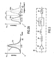
- FIGS. 2A and 2B illustrate the principle of operation of the nonlinear means 5 of the figure 1 .
- the nonlinear means 5 converts the light wave signal S of single wavelength ⁇ 0 , doubly multiplexed into amplitude and over time into a light signal S f multiplexed into wavelengths.
- the light signal S consists of a sequence of soliton-type pulses of different amplitude (denoted A 1 , A 2 , A 3 on the ordinate Y 10) distributed over time (in abscissa X 10).
- the nonlinear means 5 outputs the light wave multiplexed signal S f of which only half of the spectrum is shown diagrammatically in the diagram B of FIG. Figure 2A .
- the spectrum of the signal S f is represented solely by three spectral components S 1 , S 2 , S 3 whose amplitude is represented on the ordinate Y20 as a function of the wavelength on the abscissa X20.
- wavelength shift effect produced by the non-linear means 5 is all the more important that the peak power of the soliton pulses is high. In other words ⁇ 3 is all the greater as the amplitude A 3 is high.
- the Figure 2B illustrates, very schematically, the solitonic trapping phenomenon in a polarization-maintaining birefringent fiber 5, when a soliton pulse of amplitude A 1 is injected into the fiber at 45 ° from the proper axes of the fiber 5.
- this incident pulse is duplicated in two propagation modes along the two proper axes of the birefringent fiber 5.
- One of the modes is propagated along the fast axis while the other mode is spread along the slow axis. Since the polarization of the incident pulse is oriented at 45 ° to the proper axes of the fiber, this pulse is divided into two replicas of equal amplitude.
- Diagrams C and D of the Figure 2B represent respectively the temporal profile and the spectrum of the Soliton pulse of amplitude A 1 having undergone the solitonic trapping effect after having been injected into the fiber 5, this injection being carried out in such a way that the polarization of the initial pulse is oriented at 45 ° to the proper axes of the fiber 5.
- the dashed line profiles correspond to the mode propagated along the fast axis of the fiber 5 whereas the profiles drawn continuously correspond to the mode of the pulses propagating along the slow axis of the polarization maintaining birefringent fiber 5.
- the non-linear effect of solitonic trapping decomposes the spectrum of the soliton pulse of amplitude A 1 of central wavelength ⁇ 0 according to two spectral components denoted W 11 and W 12 , symmetrical with respect to to the central length ⁇ 0 of the incident pulse, as shown in the diagram D of the Figure 2B .
- the wavelength shift achieved by the non-linear solitonic trapping effect is denoted ⁇ 1 in absolute value.
- the spectral component W 11 is at the wavelength ⁇ 0 - ⁇ 1
- the spectral component W 12 is at the wavelength ⁇ 0 + ⁇ 1 .
- the two components W 11 , W 12 are all the more spectrally offset with respect to the length ⁇ 0 of the initial pulse, the amplitude A 1 of the initial pulse is high and therefore, the effect of Solitonic trapping is important.
- the figure 3 illustrates an exemplary embodiment of the converter 20 according to the invention.
- the converter 20 comprises a polarization-maintaining birefringent fiber 5 (non-linear means 5), a temporal compression fiber of the soliton pulses 22 (compression means 22), a polarizer 23 (polarization extraction means 23), a polarization controller 24.
- the two spectral components W 11 and W 12 of the Figure 2B generated by the polarization maintaining birefringent fiber 5 carry the same information. Therefore, at the output of this non-linear means 5, it is sufficient to recover only one of these spectral components (W 11 or W 12 ).
- the polarization controller 24 controls the polarization state of the pulses so as to ensure that the pulses are properly injected into the polarization-maintaining birefringent fiber 5 with a polarization oriented at 45 ° to the proper axes of the fiber 5. .
- the optical converter 20 may also comprise an optical amplifier 25.
- a compression means 22 consisting of a chalcogenide glass fiber element of nonlinear index n 2 equal to 2.10 -18 m 2 / W and effective area A eff equal to 50 ⁇ m 2 .
- the non-linear index n 2 of the chalcogenide glass fiber 22 is much higher than that of a standard glass fiber.
- this chalcogenide glass fiber 22 a level of chromatic dispersion D equal to 5 ps / nm / km.
- the dispersion length Z D is equal to 50.5 m.
- the average power of the corresponding pulse train is then equal to 4.4 dBm.
- the dispersion length L D and the nonlinear length L NL corresponding to the propagation of a pulse of 1 ps width and peak power P C in the chalcogenide glass nonlinear fiber 22 (compression means 22) are given by the following relationships:
- the D 2 ⁇ ⁇ c . ⁇ 2 ⁇ 2 ⁇ D
- the NL ⁇ AT eff 2 ⁇ ⁇ ⁇ not 2 ⁇ P VS
- the pulses can be considered as very close to solitons of order N if their peak power P C obeys the following relation:
- NOT 2 The D
- the compression factor is therefore about 25 (the width of the pulses after compression is equal to 40 fs) and the length of chalcogenide glass fiber 22 necessary to obtain this compression is equal to 6.65 m.
- This non-linear effect is manifested, for example, in a polarization-maintaining fiber 5, with soliton pulses whose polarization is oriented at 45 ° to the proper axes of this fiber 5.
- solitonic trapping effect can be achieved when both of the following conditions are met.
- the polarization maintaining fiber 5 (non-linear means 5) must be used in a nonlinear regime, that is to say that the incident pulses must have the physical characteristics (amplitude and width at half height ) solitons preferably of order 1 adapted to said polarization-maintaining fiber 5. Note that the solitonic trapping effect acts at best on solitons of order 1.
- Walk-off ⁇ ⁇ ⁇ ' . Z 0 ⁇ ⁇ 0 ⁇ 'being the polarization mode dispersion of the polarization maintaining fiber 5.
- ⁇ ⁇ ⁇ ⁇ not ⁇ ⁇ 0 1763 ⁇ ⁇ 2 ⁇ D
- ⁇ n the index variation between the proper birefringence axes of the polarization-maintaining fiber.
- the optical transmission system comprises 40 client terminals (or subscribers) with a client terminal rate equal to 1 Gbit / s
- 40 ridge power values judiciously distributed up to at 76 W (18.4 dBm)
- the power limit is therefore given by the power of the fundamental soliton or of order 1.
- the transmission power of each client terminal is chosen such that the wavelength of the pulses transmitted by each client terminal is converted, by solitonic trapping effect on the uplink, into a single target length. It will be noted that the amplitude of the pulses emitted by each client terminal is previously adjusted during an initial step of configuring the optical network.
- the crosstalk (or "crosstalk" in English) between different WDM channels (or different wavelengths) generated will not be noticeable due to the compression of the spectrum that will be generated in the standard fiber connecting the central terminal 1 to customer terminals.
- a chromatic dispersion compensation module must be put in place upstream of the demultiplexer 7 so as to compensate for the chromatic dispersion accumulated on the path made between the central unit 1 and the client terminals.
- the width of the initial pulses ie 40 fs
- the bit rate received by the client terminal is only 1 Gbit / s (which corresponds to a bit time equal to 1 ns).
- Bringing the pulses back to their bit time with a half-full width less than half the bit time (ie 500 ps) is more than enough.
- the tolerance on the fiber length that compensates for Standard Single Mode Fiber (SSMF) fiber is about 1 km. So, if the central-subscriber distance is 20 km, compensate for 19 km only SSMF is enough to reduce the pulse in the bit time with a width small enough for the photodetector to solve it.
- SSMF Standard Single Mode Fiber
- the numerical example above thus shows the effectiveness of the solitonic trapping effect to spectrally demultiplex a 40 Gbit / s data stream.
- the invention reconciles advantages of the two types of PON network architecture.
- a single wavelength ⁇ 0 is sent, while a low loss optical demultiplexer 7 is implemented in the network 3 so that at each client terminal (or subscriber) 11 , 12 or 13 is associated a wavelength ⁇ 1 , ⁇ 2 or ⁇ 3 which is very specific and on which are carried the data D 1 , D 2 or D 3 which are intended for it.
- the transformation based on the solitonic trapping effect according to the invention makes it possible to limit to a fiber length of a few meters in the case of a conventional PON type architecture comprising 40 subscribers. Indeed, according to the numerical example presented above, about 8 m of fiber in total is sufficient (in which are included the 6.65 m necessary for pulse compression). This has the advantage of producing fully passive converters with reduced space, easy to manufacture and low cost.
- the figures 4 and 5 show two embodiments of the central terminal 101, 100 according to the invention, in a bidirectional optical transmission system, comprising by way of example two client terminals 11 and 12.
- the central terminal 100, 101 is itself bi-directional (or "full-duplex" in English) in the sense that it can simultaneously handle downstream and upstream data flows.
- the optical transmission central terminal 100, 101 comprises a transmitter 30 intended to send on the downlink downward data D 1 , D 2 to a plurality client terminals 11, 12 during a downlink transmission phase.
- the central terminal 100, 101 furthermore comprises at least one receiver for receiving upstream data D ' 1 , D' 2 transmitted by the plurality of client terminals 11, 12 on the upstream link.
- the "downlink” is the communication link of the system according to which the downstream data D 1 , D 2 are transmitted from the central terminal 100, 101 to the plurality of client terminals 11, 12, during a downlink transmission phase.
- the "up link” is the communication link of the system according to which the upstream data D ' 1 , D' 2 are transmitted from the plurality of client terminals 11, 12 to the central terminal 100, 101, when a phase of rising transmission.
- the central terminal 100, 101 transmits to a plurality of client terminals 11, 12 the downstream data D 1 , D 2 carried by a light signal S, of single wavelength ⁇ 0 , multiplexed in amplitude and in time.
- the light signal S consists of a plurality of soliton pulses having a plurality of amplitudes.
- the signal S consists of a first series of pulses of amplitude A 1 (data D 1 ) and a second series of pulses of amplitude A 2 (data D 2 ).
- the optical converter 20 converts the single wavelength ⁇ 0 of the descending light signal S into two distinct wavelengths ⁇ 1 and ⁇ 2 as a function of the amplitudes A 1 and A 2 in order to forming a downlink wavelength multiplexed light signal S f carrying the falling data D 1 and D 2 , according to the respective wavelengths ⁇ 1 and ⁇ 2 .
- the wavelength multiplexed down-light signal S f is routed to the plurality of terminals clients 11, 12.
- routing means constituted by a WDM optical circulator 31 is placed in flux cutoff between the optical converter 20 and the optical network 3.
- the downward light signal S f multiplexed wavelengths is spectrally demultiplexed, so that each client terminal 11, 12 can receive the data intended for it (D1, D 2 respectively) according to a specific wavelength ( ⁇ 1 , ⁇ 2 respectively).
- optical demultiplexing means consisting of a WDM optical demultiplexer 7 are arranged in the optical network 3, between the WDM circulator 31 and the plurality of client terminals 11, 12.
- the optical transmission client terminals 11 and 12 each comprise a reception module or receiver respectively designated 16 and 18 for receiving the data carried by the spectral components S 1 , S 2 of the downward light signal S f .
- the downlink data D 1 (respectively D 2 ) carried by the spectral component S 1 (respectively S 2 ) at the wavelength ⁇ 1 (respectively ⁇ 2 ) are conveyed to the client terminal 11 (respectively 12) by a link optical and demodulated by the receiver 16 (respectively 18) of the client terminal 11 (respectively 12).
- S ' 1 (respectively S' 2 ) light signal emitted by the transmitter 16 (respectively 18) of the client terminal 11 (respectively 12) carrying the rising data D ' 1 (respectively D' 2 ) at the wavelength ⁇ ' 1 (respectively ⁇ ' 1 ) for the central terminal 100 or 101.
- each client terminal 11, 12 transmits the rising data D ' 1 , D' 2 to the central terminal 100, 101.
- the light signal amounts S ' 1 (respectively S' 2 ) is emitted at a specific amplitude A ' 1 (respectively A' 2 ) and with a predetermined time offset t ' 1 (respectively t' 2 ).
- the rising light signals S ' 1 and S' 2 are multiplexed in wavelengths by a multiplexer WDM 7 (multiplexing means), so as to form a rising light signal S ' f multiplexed in wavelengths.
- this multiplexer WDM 7 and the demultiplexer WDM 7 used for the downlink are constituted by a single component playing both the role of multiplexer and demultiplexer.
- the wavelength multiplexed optical signal S ' f is routed by the optical circulator 31 to at least one receiver intended to obtain the rising data D' 1 and D ' 2 emitted respectively by the customer terminals 11 and 12.
- the figure 4 illustrates a first embodiment of a bidirectional optical transmission system comprising a rising link and a downlink implementing the upstream and downstream transmission phases described above and in which the central terminal 100 comprises a reception demultiplexer 33 (second demultiplexing means), two data receivers 37 and 35 connected to the receiving demultiplexer 33, and the circulator 31 which is arranged between the converter 20 and the reception demultiplexer 33.
- the central terminal 100 comprises a reception demultiplexer 33 ( second demultiplexing means), two data receivers 37 and 35 connected to the receiving demultiplexer 33, and the circulator 31 which is arranged between the converter 20 and the reception demultiplexer 33.
- the wavelength multiplexed optical signal S ' f is spectrally demultiplexed by the reception demultiplexer 33, so as to distribute the spectral components S'1, S' 2 respectively to a first 35 and a second 37 data receiver.
- the rising data D'1 and D'2 respectively carried by the rising light signals S'1 and S'2 are respectively received by the first 35 and the second 37 data receiver according to the lengths of the data. respective waves.
- the data D ' 2 and D' 1 are recovered at the central terminal 100, after a wavelength demultiplexing of the signals S ' 1 and S' 2 produced by the reception demultiplexer 33.
- the conversion of the double amplitude and time-division multiplexed light signal S into a wavelength-multiplexed light signal S f for example from FIG. figure 4 relates to the light signals S 1 , S 2 on the downlink.
- the wavelength multiplexed upstream light signal S ' f can be transformed into an optical time division multiplexing (OTDM) signal. using an additional optical converter 21 based on the solitonic trapping effect, as illustrated in FIG. figure 5 in a second embodiment.
- OTDM optical time division multiplexing
- the wavelength multiplexed optical signal S ' f is injected into the second optical converter 21, which converts it during a transformation step by a non-linear solitonic trapping effect. in a single wavelength multiplexed ⁇ ' 0 rising signal carrying the rising data D' 1 , D ' 2.
- the optical nonlinear means of the second converter 21 is constituted by a polarization-maintaining birefringent fiber 5.
- the step of transforming the upstream transmission phase is performed by injecting the rising light signal S ' f multiplexed in wavelengths at 45 ° to the proper axes of a polarization-maintaining birefringent fiber 5.
- This second converter 21 has the effect of resetting the two channels carried by the wavelengths ⁇ ' 1 and ⁇ ' 2 on a single rising wavelength ⁇ ' 0 , whose value is taken, for example, slightly greater than that of the wavelength ⁇ 0 used in the downward direction in order to avoid interference between the uplink and the downlink.
- the single wavelength rising signal ⁇ ' 0 delivered at the output of the second optical converter 21 is demodulated by a single receiver 39 so as to recover the rising data D' 1 , D ' 2 on two separate channels.
- the advantage of this second embodiment is to have only one receiver 39 at the central terminal 101, provided that to fine-tune the transmission of the upstream signals S ' 1 , S' 2 so that these signals are correctly interposed in the time domain.
- each signal S ' 1 , S' 2 must be transmitted with a time shift t ' 1 and t' 2 such that after transformation by solitonic trapping effect, the signal obtained at the output of the second converter optical 21 is a signal multiplexed in time (OTDM signal).
Abstract
Description
L'invention se situe dans le domaine des réseaux d'accès optiques passifs de type PON « Passive Optical Network ». L'invention concerne plus particulièrement les systèmes de transmission optique à très haut débits entre un terminal central et une pluralité de terminaux clients via un réseau d'accès optique passif.The invention lies in the field of passive optical access networks of the PON type "Passive Optical Network". The invention more particularly relates to very high speed optical transmission systems between a central terminal and a plurality of client terminals via a passive optical access network.
Actuellement, les réseaux d'accès des opérateurs de télécommunications utilisent majoritairement l'accès filaire portant des technologies comme l'ADSL (« Asymetric Digital Subscriber Line »). L'optique est très peu utilisée dans les réseaux d'accès actuels, car le coût des infrastructures engendré notamment par l'installation de fibres optiques entre les centraux et les abonnés est encore prohibitif.Currently, telecommunications operators' access networks mainly use wired access using technologies such as ADSL ("Asymmetric Digital Subscriber Line"). Optics are not widely used in today's access networks, as the cost of infrastructure, including the installation of fiber optics between central offices and subscribers, is still prohibitive.
Toutefois, l'utilisation de l'optique dans des réseaux d'accès basés sur des architectures, de type PON permet la réalisation d'un bond significatif en termes de capacité, impossible à atteindre par les technologies d'accès filaire et néanmoins inéluctable en raison de la montée en débit des services à destination de l'abonné.However, the use of optics in architecture-based access networks, of the PON type, allows the achievement of a significant jump in terms of capacity, impossible for wired access technologies to achieve, and which is nonetheless unavoidable in because of the increase in the rate of services to the subscriber.
D'une manière générale, les réseaux d'accès de type PON peuvent être de deux types, les PONs dits classiques et les PONs par multiplexage en longueurs d'onde dits PONs WDM (« Wavelength Division Multiplexing »).In general, the PON type access networks can be of two types, the so-called conventional PONs and the wavelength division multiplexing PONs (Wavelength Division Multiplexing).
Les PONs classiques utilisent un accès multiple temporel de type TDMA (« Time Division Multiple Access ») et ne nécessitent qu'un seul émetteur au niveau du central de transmission. Ils se basent sur l'implémentation de coupleurs optiques 1xN (N étant un nombre de clients ou d'abonnés) afin de distribuer l'intégralité du flux de données multiplexées temporellement vers les N clients. Dans ce cas, l'information portée par un signal émis par le central de transmission est envoyée à tous les abonnés et des terminaux spécifiques, disposés chez chacun d'entre eux, permettent alors d'extraire l'information destinée réellement à ce dernier. Ainsi, les données, véhiculées à partir du central de transmission par une longueur d'onde unique, sont démultiplexées temporellement au niveau de chaque terminal client placé chez l'abonné.Conventional PONs use Time Division Multiple Access (TDMA) type multiple access and require only one transmitter at the central office. They are based on the implementation of 1xN optical couplers (N being a number of clients or subscribers) to distribute the entire temporally multiplexed data stream to the N clients. In this case, the information carried by a signal sent by the central office is sent to all subscribers and specific terminals, arranged in each of them, then extract the information actually intended for the latter. Thus, the data, conveyed from the transmission center by a single wavelength, are demultiplexed temporally at each client terminal placed at the subscriber.
Cependant, le terminal client est complexe et l'atténuation du signal par un coupleur 1xN est non négligeable. De plus, le fait que l'information est extraite au niveau de chaque terminal client présente un souci de sécurité.However, the client terminal is complex and the attenuation of the signal by a 1xN coupler is not negligible. Moreover, the fact that the information is extracted at the level of each client terminal presents a concern for security.
Les PONs WDM, quant à eux, utilisent une répartition des ressources en longueurs d'onde. Autrement dit, à chaque client est alloué une longueur d'onde spécifique. En effet, une longueur d'onde est affectée à chaque abonné au niveau du central de transmission. Chaque longueur d'onde est ensuite filtrée au niveau d'un démultiplexeur optique et est envoyée vers l'abonné correspondant. Ce type de réseau nécessite donc l'utilisation d'un multiplex de longueurs d'onde, en quantité égale au nombre d'abonnés, et d'un démultiplexeur.WDM PONs, on the other hand, use a distribution of wavelength resources. In other words, each client is allocated a specific wavelength. Indeed, a wavelength is assigned to each subscriber at the transmission center. Each wavelength is then filtered at an optical demultiplexer and sent to the corresponding subscriber. This type of network therefore requires the use of a multiplex of wavelengths, in an amount equal to the number of subscribers, and a demultiplexer.
Ainsi, le réseau de type PON WDM a l'avantage, par rapport au réseau PON classique, de la simplicité, chaque longueur d'onde étant affectée à un abonné spécifique, et de la performance, un démultiplexeur optique étant nettement moins atténuant qu'un coupleur 1xN.Thus, the PON WDM type network has the advantage, compared to the conventional PON network, of simplicity, each wavelength being assigned to a specific subscriber, and performance, an optical demultiplexer being significantly less attenuating than a 1xN coupler.
En revanche, il est plus coûteux car il utilise un plus grand nombre de longueurs d'onde et un élément de routage (démultiplexeur optique) plus onéreux que le simple coupleur 1xN.However, it is more expensive because it uses a larger number of wavelengths and a routing element (optical demultiplexer) more expensive than the single 1xN coupler.
Il est aussi connu un central comportant un laser accordable émettant, par commutation, une pluralité de longueurs d'ondes différentes. Ainsi, il adresse les clients l'un après l'autre en accordant sa longueur d'onde. Cependant, le laser accordable doit fonctionner à un débit N fois supérieur à celui alloué aux clients, et il faut ajouter un temps de commutation qui, dans le meilleur des cas, est de 50 ns qui est loin d'être négligeable dans des communications à très haut débit.It is also known a central comprising a tunable laser emitting, by switching, a plurality of different wavelengths. Thus, it addresses the customers one after the other by granting its wave length. However, the tunable laser must operate at a rate N times greater than that allocated to the customers, and we must add a switching time which, in the best case, is 50 ns which is far from negligible in communications to very high speed.
Les publications
L'invention a pour but de remédier à ces inconvénients, et de simplifier la transmission optique entre un terminal central et une pluralité de terminaux clients.The object of the invention is to remedy these drawbacks, and to simplify the optical transmission between a central terminal and a plurality of client terminals.
Ces buts sont atteints grâce à un procédé de transmission optique entre un terminal central et une pluralité de terminaux clients via un réseau optique, dans lequel des données descendantes D1, D2 sont transmises du terminal central vers la pluralité de terminaux client, lors d'une phase de transmission descendante.These goals are achieved by an optical transmission method between a central terminal and a plurality of client terminals via an optical network, wherein downstream data D 1 , D 2 are transmitted from the central terminal to the plurality of client terminals, when a downward transmission phase.
Selon la présente invention, la phase de transmission descendante comprend les étapes suivantes :
- émission par le terminal central d'un signal lumineux descendant de longueur d'onde unique doublement multiplexé en amplitude et dans le temps et portant les données descendantes D1, D2 destinées à être reçues par la pluralité de terminaux clients, le signal lumineux descendant de longueur d'onde unique étant constitué d'impulsions de type soliton comportant une pluralité d'amplitudes A1, A2;
- transformation par un effet non linéaire de piégeage solitonique de la longueur d'onde unique λ0 du signal lumineux descendant en une pluralité de longueurs d'onde λ1, λ2 en fonction de la pluralité d'amplitudes A1, A2 de manière à former un signal lumineux descendant Sf multiplexé en longueurs d'onde ;
- routage du signal lumineux descendant Sf multiplexé en longueurs d'ondes vers la pluralité de terminaux clients;
- démultiplexage en longueurs d'onde du signal lumineux descendant Sf multiplexé en longueurs d'onde, de sorte que chaque terminal client reçoit les données qui lui sont destinées D1, D2 selon une longueur d'onde spécifique λ1, λ2.
- transmission by the central terminal of a downstream light signal of double wavelength doubled multiplexed in amplitude and in time and carrying the downward data D 1 , D 2 intended to be received by the plurality of client terminals, the downward light signal single wavelength consisting of soliton type pulses having a plurality of amplitudes A 1 , A 2 ;
- transformation by a solitonic trapping nonlinear effect of the single wavelength λ 0 of the downward light signal into a plurality of wavelengths λ 1 , λ 2 as a function of the plurality of amplitudes A 1 , A 2 so forming a downlink light signal S f multiplexed in wavelengths;
- routing the downlinked downlink light signal S f wavelength multiplexed to the plurality of client terminals;
- demultiplexing in wavelengths the wavelength multiplexed downlink light signal S f , so that each client terminal receives the data intended for it D 1 , D 2 according to a specific wavelength λ 1 , λ 2 .
Selon un aspect de l'invention, des données montantes D'1, D'2 sont transmises de la pluralité de terminaux clients vers un terminal central, lors d'une phase de transmission montante. Dans ce cas, les étapes de transformation et de routage mentionnées ci-dessus sont réalisées par le terminal central.According to one aspect of the invention, upstream data D ' 1 , D' 2 are transmitted from the plurality of client terminals to a central terminal, during an upstream transmission phase. In this case, the transformation and routing steps mentioned above are performed by the central terminal.
Ainsi, l'effet de piégeage solitonique, lors de l'étape de transformation, permet de convertir un signal lumineux, de longueur d'onde unique, doublement multiplexé en amplitude et dans le temps émis par le terminal central, en un signal lumineux multiplexé en longueurs d'onde comportant une pluralité de longueurs d'onde, de telle sorte que chacune de ces longueurs d'onde porte les données propres à chaque terminal client. Cette transformation est particulièrement bien adaptée à la conversion de signaux optiques à très hauts débits. Le terme « très hauts débits » désignera par la suite des débits de l'ordre de 40 à 160 Gbits/s.Thus, the solitonic trapping effect, during the transformation step, makes it possible to convert a light signal, of a single wavelength, doubly multiplexed in amplitude and in time transmitted by the central terminal, into a multiplexed light signal. in wavelengths having a plurality of wavelengths, such that each of these wavelengths carries the data specific to each client terminal. This transformation is particularly well suited to the conversion of optical signals at very high rates. The term "very high bit rates" will subsequently refer to bit rates in the range of 40 to 160 Gbit / s.
Le procédé selon l'invention permet ainsi de diminuer les coûts d'un réseau de transmission optique de type PON (par rapport aux réseaux de type PON WDM actuels), tout en augmentant la performance notamment en termes débits de transmission, la sécurité et la simplicité du réseau de transmission.The method according to the invention thus makes it possible to reduce the costs of a PON-type optical transmission network (compared to current WDM PON type networks), while increasing the performance notably. in terms of transmission rates, the security and simplicity of the transmission network.
Selon un aspect et réalisation, la phase de transmission montante du procédé de transmission optique selon l'invention comprend les étapes suivantes :
- émission d'une pluralité de signaux lumineux montants S'1, S'2 vers le terminal central, chaque signal lumineux montant portant respectivement les données montantes D'1. D'2 à une longueur d'onde distincte λ'1, λ'2 et étant respectivement émis par un terminal client de la pluralité de terminaux clients selon une amplitude A'1, A'2 spécifique et avec un décalage temporel t'1, t'2 prédéterminé;
- multiplexage en longueurs d'onde de la pluralité de signaux lumineux montants S'1, S'2, de manière à former un signal lumineux montant S'f multiplexé en longueurs d'ondes ; et
- routage du signal lumineux montant S'f multiplexé en longueurs d'ondes vers au moins un récepteurs destiné à obtenir les données D'1, D'2 émises par chaque terminal client de la pluralité de terminaux clients.
- transmitting a plurality of rising light signals S ' 1 , S' 2 to the central terminal, each rising light signal respectively carrying the rising data D ' 1 . D 2 at a distinct wavelength λ ' 1 , λ' 2 and being respectively transmitted by a client terminal of the plurality of client terminals according to a specific amplitude A ' 1 , A' 2 and with a time shift t ' 1 , t ' 2 predetermined;
- wavelength division multiplexing of the plurality of rising light signals S ' 1 , S' 2 , so as to form a wavelength division multiplexed light signal S 'f; and
- routing the light signal S ' f multiplexed in wavelengths to at least one receiver for obtaining data D' 1 , D ' 2 issued by each client terminal of the plurality of client terminals.
Selon un premier mode de réalisation de l'invention, la phase de transmission montante comprend en outre :
- une étape de démultiplexage en longueurs d'ondes, lors de laquelle le signal lumineux montant S'f multiplexé en longueurs d'ondes est spectralement démultiplexé en une pluralité de composantes spectrales ; et
- une étape de réception des données montantes par une pluralité de récepteurs, lors de laquelle chacune des composantes spectrales portant les données montantes émises par un terminal client sur une longueur d'onde respective est reçue par un récepteur de la pluralité de récepteurs.
- a wavelength demultiplexing step, wherein the wavelength division multiplexed light signal S ' f is spectrally demultiplexed into a plurality of spectral components; and
- a step of receiving the rising data by a plurality of receivers, wherein each of the spectral components carrying the rising data transmitted by a client terminal over a respective wavelength is received by a receiver of the plurality of receivers.
Selon un deuxième mode de réalisation, la phase de transmission montante du procédé de transmission optique selon l'invention comprend en outre :
- une étape de transformation, lors de laquelle le signal lumineux montant S'f multiplexé en longueur d'onde est converti par un effet non linéaire de piégeage solitonique en un signal montant de longueur d'onde unique λ'0 multiplexé dans le temps portant les données montantes ; et
- une étape de réception du signal montant de longueur d'onde unique λ'0 par un récepteur unique.
- a transformation step, in which the wavelength multiplexed optical signal S ' f is converted by a non-linear effect of soliton trapping in a single wave length signal amount λ '0 time multiplexed on the uplink data; and
- a step of receiving the single wavelength rising signal λ ' 0 by a single receiver.
Le procédé selon l'invention permet de réaliser simultanément la conversion par effet de piégeage solitonique d'un signal OTDM (émis par le terminal central) en un signal WDM (destiné à la pluralité de terminaux clients) et réciproquement la conversion d'un signal WDM (issu de la pluralité de terminaux clients) en un signal OTDM (destiné au terminal central). Le procédé selon l'invention permet ainsi d'allier les avantages d'un mode de transmission TDM aux avantages d'un mode de transmission WDM.The method according to the invention makes it possible to carry out simultaneously the solitonic trapping effect of an OTDM signal (transmitted by the central terminal) into a WDM signal (intended for the plurality of client terminals) and conversely the conversion of a signal. WDM (from the plurality of client terminals) into an OTDM signal (for the central terminal). The method according to the invention thus makes it possible to combine the advantages of a TDM transmission mode with the advantages of a WDM transmission mode.
De manière avantageuse, les données montantes D'1, D'2 sont récupérées à l'aide d'un unique récepteur au niveau du terminal central, permettant ainsi de minimiser l'encombrement du terminal central.Advantageously, the upstream data D ' 1 , D' 2 are retrieved using a single receiver at the central terminal, thus making it possible to minimize the congestion of the central terminal.
Selon une caractéristique de l'invention, le procédé selon l'invention comprend, préalablement à l'étape de transformation, une étape de compression temporelle des impulsions de type soliton.According to one characteristic of the invention, the method according to the invention comprises, prior to the transformation step, a step of temporal compression of the soliton-type pulses.
Une telle étape de compression des impulsions soliton dans le domaine temporel a pour effet d'augmenter la puissance crête de ces impulsions, améliorant ainsi l'excitation par l'effet non linéaire de piégeage solitonique.Such a step of compressing soliton pulses in the time domain has the effect of increasing the peak power of these pulses, thus improving the excitation by the non-linear effect of solitonic trapping.
Selon une autre caractéristique de l'invention, lors de la phase de transmission descendante du procédé de transmission optique selon l'invention, l'étape de transformation par effet non linéaire de piégeage solitonique est réalisée en injectant le signal lumineux descendant S de longueur d'onde unique λ0 à 45° des axes propres d'une fibre biréfringente à maintien de polarisation.According to another characteristic of the invention, during the downward transmission phase of the optical transmission method according to the invention, the step of transformation by non-linear effect of solitonic trapping is performed by injecting the downward light signal S of length d single wave λ 0 at 45 ° of the proper axes of a polarization-maintaining birefringent fiber.
Ceci permet de piéger les impulsions soliton dans le domaine temporel de manière optimale.This makes it possible to trap the soliton pulses in the time domain optimally.
Selon une autre caractéristique de l'invention, lors de la phase de transmission montante du procédé de transmission optique selon l'invention, l'étape de transformation par effet non linéaire de piégeage solitonique est réalisée en injectant ledit signal lumineux montant S'f multiplexé en longueurs d'onde à 45° des axes propres d'une fibre biréfringente à maintien de polarisation.According to another characteristic of the invention, during the upward transmission phase of the optical transmission method according to the invention, the step of transformation by non-linear solitonic trapping effect is performed by injecting said light signal amount S ' f multiplexed in 45-degree wavelengths of the proper axes of a polarization-maintaining birefringent fiber.
Selon une autre caractéristique de l'invention, une extraction du signal multiplexé en longueurs d'onde selon un des axes propres de la fibre biréfringente à maintien de polarisation est réalisée.According to another characteristic of the invention, an extraction of the multiplexed signal in wavelengths along one of the proper axes of the polarization-maintaining birefringent fiber is carried out.
Du fait de la biréfringence de la fibre, toute impulsion incidente se dédouble selon deux modes propres de propagation, chaque mode se propageant selon l'un des axes propres de la fibre à maintien de polarisation. En plaçant, par exemple, un polariseur orienté selon l'un des axes propres de la fibre, il est possible de récupérer l'un des deux modes propres du spectre et par conséquent, une des composantes fréquentielles générée par l'effet de piégeage solitonique portée par un des axes propres de la fibre.Because of the birefringence of the fiber, any incident pulse splits into two natural modes of propagation, each mode propagating along one of the proper axes of the polarization-maintaining fiber. By placing, for example, a polarizer oriented according to one of Eigen axes of the fiber, it is possible to recover one of the two eigenmodes of the spectrum and consequently, one of the frequency components generated by the solitonic trapping effect carried by one of the axes proper of the fiber.
L'invention vise aussi un système de transmission optique entre un terminal central, une pluralité de terminaux clients via un réseau optique, dans lequel le terminal central est destiné à émettre sur un lien descendant des données descendantes D1, D2 à destination de la pluralité de terminaux clients. Selon un aspect de l'invention, le système de transmission optique est bidirectionnel. Dans ce cas, le terminal central est en outre destiné à recevoir sur un lien montant des données montantes D'1, D'2 en provenance de la pluralité de terminaux clients.The invention also relates to an optical transmission system between a central terminal, a plurality of client terminals via an optical network, in which the central terminal is intended to transmit downlink data D 1 , D 2 to the destination. plurality of client terminals. According to one aspect of the invention, the optical transmission system is bidirectional. In this case, the central terminal is also intended to receive on a rising link rising data D ' 1 , D' 2 from the plurality of client terminals.
Sur le lien descendant, le système selon l'invention comprend :
- des moyens d'émission d'un signal lumineux descendant S de longueur d'onde unique λ0 et portant les données descendantes D1, D2, le signal lumineux descendant S étant doublement multiplexé en temps et en amplitude et constitué d'impulsions de type soliton comportant une pluralité d'amplitudes A1, A2 ;
- des moyens d'émission d'une pluralité de signaux lumineux montants S'1, S'2 vers le terminal central, chaque signal lumineux montant portant respectivement les données montantes D'1, D'2 à une longueur d'onde distincte λ'1, λ'2 et étant respectivement émis par un terminal client de la pluralité de terminaux clients selon une amplitude A'1, A'2 spécifique et avec un décalage temporel t'1, t'2 prédéterminé;
- des moyens de multiplexage pour multiplexer en longueurs d'onde la pluralité de signaux lumineux montants S'1, S'2 de manière à former un signal lumineux montant S'f multiplexé en longueurs d'ondes ;
- des moyens de routage du signal lumineux montant S'f multiplexé en longueurs d'ondes ; et
- au moins un récepteur destiné à obtenir les données montantes D'1, D'2, émises par chaque terminal client de la pluralité de terminaux clients.
- means for transmitting a downlink light signal S of a single wavelength λ 0 and carrying the descending data D 1 , D 2 , the downstream light signal S being doubly multiplexed in time and in amplitude and constituted by pulses of soliton type having a plurality of amplitudes A 1 , A 2 ;
- means for transmitting a plurality of rising light signals S ' 1 , S' 2 towards the central terminal, each rising light signal respectively the rising data D ' 1 , D' 2 at a distinct wavelength λ ' 1 , λ' 2 and being respectively transmitted by a client terminal of the plurality of client terminals according to a specific amplitude A ' 1 , A' 2 and with a time offset t ' 1 , t' 2 predetermined;
- multiplexing means for wavelength multiplexing the plurality of rising light signals S ' 1 , S' 2 so as to form a wavelength division multiplexed light signal S 'f;
- means for routing the rising light signal S ' f multiplexed in wavelengths; and
- at least one receiver for obtaining the upstream data D ' 1, D' 2 , transmitted by each client terminal of the plurality of client terminals.
Ainsi, l'architecture du système bidirectionnel selon l'invention est très simple à réaliser et est adapté à fonctionner à des débits de transmission très élevés (de 40 à 160 Gbit/s). Sur le lien descendant, le terminal central émet les données descendantes à une longueur d'onde unique.Thus, the architecture of the bidirectional system according to the invention is very simple to implement and is adapted to operate at very high transmission rates (from 40 to 160 Gbit / s). On the downlink, the central terminal transmits the downstream data at a single wavelength.
De plus, le système présente une sécurité optimale et une bonne performance car il permet d'associer une longueur d'onde spécifique à chaque terminal client. De cette manière, contrairement aux PONs classiques, chaque terminal client reçoit, sur une longueur d'onde spécifique, uniquement les données qui lui sont destinées.In addition, the system has optimal security and good performance because it allows to associate a specific wavelength to each client terminal. In this way, unlike conventional PONs, each client terminal receives, on a specific wavelength, only the data intended for it.
Selon un premier mode de réalisation, le système selon l'invention, comprend en outre sur le lien montant:
- des deuxièmes moyens de démultiplexage pour démultiplexer spectralement le signal lumineux montant S'f multiplexé en longueurs d'ondes en une pluralité de composantes spectrales ; et
- une pluralité de récepteurs en sortie des deuxièmes moyens de démultiplexage, chaque récepteur étant adapté à recevoir des données montantes portées par chaque composante spectrale et émises par un terminal client sur une longueur d'onde respective.
- second demultiplexing means for spectrally demultiplexing the wavelength division multiplexed light signal S ' f into a plurality of spectral components; and
- a plurality of receivers at the output of the second demultiplexing means, each receiver being adapted to receive rising data carried by each spectral component and transmitted by a client terminal over a respective wavelength.
Système un deuxième mode de réalisation, le système selon l'invention comprend en outre sur le lien montant :
- un moyen non linéaire destiné à convertir par un effet de piégeage solitonique, le signal lumineux montant S'f multiplexé en longueur d'onde en un signal montant de longueur d'onde unique λ'0 multiplexé dans le temps portant les données montantes ; et
- des moyens de réception du signal montant de longueur d'onde unique λ'0.
- nonlinear means for converting by a solitonic trapping effect the wavelength multiplexed upstream light signal S ' f into a single wavelength multiplexed time wavelength rising signal λ' 0 carrying the rising data; and
- means for receiving the signal amount of single wavelength λ ' 0 .
Selon une autre caractéristique de l'invention, le système selon l'invention comprend, en outre, un moyen de compression temporelle destiné à comprimer les impulsions de type soliton et situé en amont du moyen non linéaire.According to another characteristic of the invention, the system according to the invention further comprises a temporal compression means for compressing the soliton type pulses and located upstream of the nonlinear means.
Selon une autre caractéristique de la présente invention, ce moyen de compression temporelle est une fibre de compression non linéaire de type à verre chalcogénure.According to another characteristic of the present invention, this temporal compression means is a chalcogenide glass-type nonlinear compression fiber.
Avantageusement, l'utilisation d'un composant tout optique tel qu'une fibre optique en verre chalcogénure permet de comprimer des impulsions soliton dans le domaine temporel, en s'affranchissant d'un composant actif.Advantageously, the use of an all-optical component such as a chalcogenide glass optical fiber makes it possible to compress soliton pulses in the time domain, by dispensing with an active component.
De plus, vis-à-vis de la compression temporelle, une fibre de type à verre chalcogénure présente l'avantage d'avoir un indice non linéaire beaucoup plus élevé que celui d'une fibre à verre standard. Ainsi des taux de compression non linéaire des impulsions dans le domaine temporel peuvent être plus facilement atteints avec ce type de fibre qu'avec une fibre standard, limitant ainsi l'encombrement du moyen de compression temporelle ainsi que la puissance requise pour exacerber l'effet de compression.In addition, with respect to time compression, a chalcogenide glass type fiber has the advantage of having a much higher non-linear index than that of a standard glass fiber. Thus nonlinear pulse compression rates in the time domain can be more easily achieved with this type of fiber than with a standard fiber, thus limiting the size of the time compression means and the power required to exacerbate the effect. compression.
Selon une autre caractéristique de l'invention, le moyen non linéaire est une fibre biréfringente à maintien de polarisation comportant deux axes propres distincts.According to another characteristic of the invention, the non-linear means is a polarization-maintaining birefringent fiber comprising two distinct distinct axes.
Avantageusement, la longueur de fibre nécessaire pour réaliser le décalage en longueur d'onde par l'effet de piégeage solitonique dans le cas d'une fibre biréfringente à maintien de polarisation est négligeable.Advantageously, the length of fiber necessary to achieve the wavelength shift by the solitonic trapping effect in the case of a polarization-maintaining birefringent fiber is negligible.
Selon une autre caractéristique de l'invention, le système comprend, en outre, des moyens pour extraire le signal lumineux descendant multiplexé en longueurs d'onde selon un des axes propres de la fibre biréfringente, moyens choisis parmi les éléments suivants :
- un polariseur ;
- un filtre optique passe-bande.
- a polarizer;
- an optical bandpass filter.
Selon une autre caractéristique de l'invention, le réseau optique est un réseau d'accès optique passif de type PON.According to another characteristic of the invention, the optical network is a passive optical access network of the PON type.
Etant donné que le système décrit selon l'invention ne nécessite aucun composant de type actif, notamment pour la conversion d'un double multiplexage en temps et en amplitude en un multiplexage en longueur d'ondes, ce type de réseau de transmission optique est particulièrement adapté à un réseau optique passif de type PON qui, par définition, n'utilise pas de composants actifs pour permettre l'acheminement des signaux.Since the system described according to the invention does not require any active type component, in particular for the conversion of a dual time and amplitude multiplexing into a wavelength division multiplexing, this type of optical transmission network is particularly adapted to a passive optical network of PON type which, by definition, does not use active components to allow the routing of the signals.
L'invention vise également un terminal central de transmission optique comprenant :
- un émetteur destiné à émettre des données descendantes D1, D2 à destination d'une pluralité de terminaux clients, les données descendantes étant portées par un signal lumineux descendant S de longueur d'onde unique λ0 comprenant une pluralité d'impulsions de type soliton, le signal lumineux descendant S étant doublement multiplexé en temps et en amplitude et comportant une pluralité d'amplitudes A1, A2 ; et
- au moins un récepteur adapté à recevoir des données montantes D'1, D'2 émises par la pluralité de terminaux clients.
- a transmitter for transmitting downstream data D 1 , D 2 to a plurality of client terminals, the downstream data being carried by a downlink light signal S of a single wavelength λ 0 comprising a plurality of type pulses soliton, the downstream light signal S being doubly multiplexed in time and amplitude and having a plurality of amplitudes A 1 , A 2 ; and
- at least one receiver adapted to receive upstream data D ' 1 , D' 2 transmitted by the plurality of client terminals.
Le terminal selon l'invention est caractérisé en ce qu'il comprend en outre :
- un moyen de routage permettant de router les données descendantes et montantes ; et
- un premier convertisseur optique placé entre l'émetteur et le moyen de routage et comprenant un moyen non linéaire pour transformer, par un effet de piégeage solitonique, la longueur d'onde unique λ0 du signal lumineux descendant S en une pluralité de longueurs d'onde λ1, λ2 en fonction de la pluralité d'amplitudes A1, A2, de manière à former un signal lumineux descendant Sf multiplexé en longueurs d'onde.
- routing means for routing the downstream and upstream data; and
- a first optical converter placed between the transmitter and the routing means and comprising a non-linear means for transforming, by a solitonic trapping effect, the unique wavelength λ 0 of the down-light signal S into a plurality of lengths of wave λ 1 , λ 2 as a function of the plurality of amplitudes A 1 , A 2 , so as to form a wavelength multiplexed down-light signal S f .
Avantageusement, l'architecture de l'équipement est très simple, car il suffit d'un seul émetteur pour émettre un signal lumineux à longueur d'onde unique, doublement multiplexé en amplitude et dans le temps et d'un convertisseur optique permettant d'obtenir un signal multiplexé en longueur d'ondes.Advantageously, the architecture of the equipment is very simple, since it suffices for a single transmitter to emit a single wavelength light signal, doubly multiplexed in amplitude and in time and an optical converter allowing obtain a signal wavelength multiplexed.
Grâce au moyen de routage, un flux de données descendant émis par le terminal central est routé vers la pluralité de terminaux clients, pendant qu'un flux de données montant émis par les terminaux clients est routé vers au moins un récepteur de données du terminal central.. Ce moyen de routage (par exemple, un circulateur optique) présente donc l'avantage de rendre le terminal central « full duplex » dans la mesure où le terminal central peut émettre et recevoir des données simultanément.Through the routing means, a downstream data stream transmitted by the central terminal is routed to the plurality of client terminals, while an upstream data stream transmitted by the client terminals is routed to at least one data receiver of the central terminal. This routing means (for example, an optical circulator) thus has the advantage of making the central terminal "full duplex" insofar as the central terminal can send and receive data simultaneously.
De manière avantageuse, cette solution permet de partager la même infrastructure de réseau pour le lien montant que pour le lien descendant, minimisant ainsi la complexité et le coût global du système de transmission.Advantageously, this solution makes it possible to share the same network infrastructure for the upstream link as for the downlink, thus minimizing the complexity and overall cost of the transmission system.
Selon un premier mode de réalisation, le terminal central selon l'invention comprend un démultiplexeur de réception, une pluralité de récepteurs destinés à recevoir les données montantes D'1, D'2, chacun de ces récepteurs étant relié au démultiplexeur de réception et le moyen de routage étant disposé entre le premier moyen non linéaire et le démultiplexeur de réception.According to a first embodiment, the central terminal according to the invention comprises a reception demultiplexer, a plurality of receivers intended to receive the rising data D ' 1 , D' 2 , each of these receivers being connected to the receiving demultiplexer and the routing means being disposed between the first non-linear means and the receiving demultiplexer.
Selon un deuxième mode de réalisation, le terminal central selon l'invention comprend en outre un récepteur de données et un deuxième convertisseur optique comprenant un moyen non linéaire, le deuxième convertisseur optique étant disposé entre le moyen de routage et le récepteur de données.According to a second embodiment, the central terminal according to the invention further comprises a data receiver and a second optical converter comprising a non-linear means, the second optical converter being arranged between the routing means and the data receiver.
Ce deuxième mode de réalisation présente l'avantage de n'utiliser qu'un seul récepteur au niveau du terminal central.This second embodiment has the advantage of using only one receiver at the central terminal.
L'invention vise aussi un terminal client de transmission optique, comportant un récepteur/émetteur destiné à recevoir ou émettre des données portées par un signal lumineux ayant une longueur d'onde spécifique depuis ou vers un terminal central comportant les caractéristiques ci-dessus.The invention also relates to an optical transmission client terminal, comprising a receiver / transmitter for receiving or transmitting data carried by a light signal having a specific wavelength from or to a central terminal having the above characteristics.
Ainsi, le terminal client présente une grande sécurité et une grande simplicité car il n'est pas nécessaire d'avoir un moyen spécifique pour extraire les données qui lui sont destinées.Thus, the client terminal has great security and simplicity because it is not necessary to have a specific way to extract the data intended for it.
D'autres particularités et avantages de l'invention ressortiront à la lecture de la description faite, ci-après, à titre indicatif mais non limitatif, en référence aux dessins annexés, sur lesquels :
- la
figure 1 illustre un exemple très schématique d'un système de transmission optique entre un terminal central et une pluralité de terminaux clients via un réseau optique et comportant un moyen non linéaire selon l'invention ; - les
figures 2A et2B illustrent le principe de fonctionnement du moyen non linéaire de lafigure 1 ; - la
figure 3 illustre un mode de réalisation d'un convertisseur optique selon l'invention ; et - les
figures 4 et 5 illustrent deux modes de réalisation d'un système de transmission optique selon l'invention.
- the
figure 1 illustrates a very schematic example of an optical transmission system between a central terminal and a plurality of client terminals via an optical network and comprising a non-linear means according to the invention; - the
Figures 2A and2B illustrate the principle of operation of the nonlinear means offigure 1 ; - the
figure 3 illustrates an embodiment of an optical converter according to the invention; and - the
figures 4 and5 illustrate two embodiments of an optical transmission system according to the invention.
La
Dans cet exemple, le terminal central 1 émet des données descendantes (D1, D2, D3) portées par un signal lumineux descendant S de longueur unique λ0, doublement multiplexé en amplitude et dans le temps, comportant une pluralité d'amplitudes (A1, A2, A3).In this example, the
Le système de transmission comprend un moyen non linéaire 5 et un démultiplexeur 7 (premiers moyens de démultiplexage) en longueurs d'onde, ce démultiplexeur 7 étant compris dans le réseau optique 3.The transmission system comprises a nonlinear means 5 and a demultiplexer 7 (first means of demultiplexing) in wavelengths, this
Le moyen non linéaire 5 permet de convertir le signal lumineux descendant S de longueur d'onde unique λ0, doublement multiplexé en amplitude et dans le temps en un signal lumineux descendant Sf multiplexé en longueurs d'onde, comportant une pluralité de composantes spectrales notées S1, S2, S3 selon une pluralité de longueur d'ondes (λ0 ± Δλ1, λ0 ± Δλ2, λ0 ± Δλ3). Par exemple, la composante spectrale S1 de longueur λ1 = λ0 ± Δλ1 porte les données D1 destinées au terminal client 11.The nonlinear means 5 makes it possible to convert the downstream light signal S of single wavelength λ 0 , doubly multiplexed in amplitude and in time into a wavelength multiplexed downlink light S f , comprising a plurality of spectral components. denoted S 1 , S 2 , S 3 according to a plurality of wavelengths (λ 0 ± Δλ 1 , λ 0 ± Δλ 2 , λ 0 ± Δλ 3 ). For example, the spectral component S 1 of length λ 1 = λ 0 ± Δλ 1 carries the data D 1 intended for the
Le démultiplexeur 7 en longueurs d'onde situé entre le moyen non linéaire 5 et les terminaux clients 11, 12, 13 permet de démultiplexer en longueurs d'onde le signal Sf, en répartissant spatialement la pluralité de composantes spectrales (S1, S2 ,S3) selon la pluralité de longueurs d'onde, de sorte que chaque terminal client reçoit uniquement les données qui lui sont destinées. Par exemple, le terminal client 12 reçoit les données D2 portée par le signal S2 à la longueur λ2 = λ0 ± Δλ2.The
Les
Le moyen non linéaire 5 assure la conversion du signal lumineux S de longueur onde unique λ0, doublement multiplexé en amplitude et dans le temps en un signal lumineux Sf multiplexé en longueurs d'onde.The nonlinear means 5 converts the light wave signal S of single wavelength λ 0 , doubly multiplexed into amplitude and over time into a light signal S f multiplexed into wavelengths.
Tel que représenté sur le diagramme A de la
Par effet de piégeage solitonique, toutes les impulsions ayant une même amplitude (ou puissance) subissent un même décalage fréquentiel (ou décalage en longueur d'onde) en fonction de la valeur de leur amplitude, de sorte que la longueur d'onde initiale λ0 de ces impulsions soit convertie en longueurs d'ondes spécifiques (λ1 = λ0 ± Δλ1, λ2 = λ0 ± Δλ2, ou λ3 = λ0 ± Δλ3 dans cet exemple). Par exemple, l'ensemble des impulsions entrant dans le moyen non linéaire 5 à la longueur d'onde λ0 et avec une amplitude A2 sont converties en un ensemble d'impulsions de longueurs d'onde λ2 = λ0 ± Δλ2 représentées schématiquement par le signal lumineux S2.By solitonic trapping effect, all the pulses having the same amplitude (or power) undergo the same frequency shift (or wavelength shift) as a function of the value of their amplitude, so that the initial wavelength λ 0 of these pulses is converted into specific wavelengths (λ 1 = λ 0 ± Δλ 1 , λ 2 = λ 0 ± Δλ 2 , or λ 3 = λ 0 ± Δλ 3 in this example). For example, all the pulses entering the non-linear means 5 at the wavelength λ 0 and with an amplitude A 2 are converted into a set of wavelength pulses λ 2 = λ 0 ± Δλ 2 schematically represented by the light signal S 2 .
Ainsi, le moyen non linéaire 5 fournit en sortie le signal lumineux Sf multiplexé en longueurs d'ondes dont seulement la moitié du spectre est représentée schématiquement sur le diagramme B de la
Lors de l'étape de transformation par effet de piégeage solitonique, les impulsions d'amplitude A3 de longueur d'onde λ0 portant les données D3 destinées au terminal client 13 sont converties en un signal lumineux S3, de longueur d'onde λ3 = λ0 ± Δλ3, ce signal étant destiné uniquement au terminal client 13.During the step of transformation by solitonic trapping effect, the amplitude pulses A 3 of wavelength λ 0 carrying the data D 3 intended for the
On notera que l'effet de décalage en longueur d'onde produit par le moyen non linéaire 5 est d'autant plus important que la puissance crête des impulsions soliton est élevée. Autrement dit Δλ3 est d'autant plus grand que l'amplitude A3 est élevée.Note that the wavelength shift effect produced by the non-linear means 5 is all the more important that the peak power of the soliton pulses is high. In other words Δλ3 is all the greater as the amplitude A 3 is high.
La
En raison de la biréfringence de la fibre 5, cette impulsion incidente se duplique en deux modes de propagation selon les deux axes propres de la fibre biréfringente 5. L'un des modes se propage selon l'axe rapide tandis que l'autre mode se propage selon l'axe lent. Etant donné que la polarisation de l'impulsion incidente est orientée à 45° des axes propres de la fibre, cette impulsion se divise selon deux répliquas d'amplitude égale.Due to the birefringence of the
Les diagrammes C et D de la
Sur ces diagrammes C et D, les profils tracés en pointillés correspondent au mode se propageant selon l'axe rapide de la fibre 5 alors que les profils tracés en continu correspondent au mode des impulsions se propageant selon l'axe lent de la fibre biréfringente à maintien de polarisation 5.On these diagrams C and D, the dashed line profiles correspond to the mode propagated along the fast axis of the
Sous l'effet du piégeage solitonique, les deux modes propres de l'impulsion notés I11 et I12 sont piégés dans le domaine temporel autour du temps noté t=0 sur l'axe des abscisses X21. Ce piégeage est représenté sur le diagramme C de la
Cependant, dans le domaine fréquentiel, l'effet non linéaire de piégeage solitonique décompose le spectre de l'impulsion soliton d'amplitude A1 de longueur d'onde centrale λ0 selon deux composantes spectrales notées W11 et W12, symétriques par rapport à la longueur centrale λ0 de l'impulsion incidente, tel que représenté sur le diagramme D de la
Sur ce diagramme, le décalage en longueur d'onde réalisé par l'effet non linéaire de piégeage solitonique est noté Δλ1 en valeur absolue. Ainsi, la composante spectrale W11 est à la longueur d'onde λ0-Δλ1, tandis que la composante spectrale W12 est à la longueur d'onde λ0+Δλ1. Les deux composantes W11, W12 sont d'autant plus spectralement décalées par rapport à la longueur λ0 de l'impulsion initiale, que l'amplitude A1 de l'impulsion initiale est élevée et par conséquent, que l'effet de piégeage solitonique est important.In this diagram, the wavelength shift achieved by the non-linear solitonic trapping effect is denoted Δλ 1 in absolute value. Thus, the spectral component W 11 is at the wavelength λ 0 -Δλ 1 , whereas the spectral component W 12 is at the wavelength λ 0 + Δλ 1 . The two components W 11 , W 12 are all the more spectrally offset with respect to the length λ 0 of the initial pulse, the amplitude A 1 of the initial pulse is high and therefore, the effect of Solitonic trapping is important.
Ainsi, de manière générale, la fibre biréfringente à maintien de polarisation 5 convertit la longueur d'onde λ0 initiale d'une impulsion soliton d'amplitude An (où n = 1, 2 ou 3 dans cet exemple) en deux longueurs d'onde distinctes λ0+Δλn et λ0-Δλn, ces deux longueurs d'ondes étant symétriques par rapport à la longueur d'onde λ0, où Δλn est le décalage spectral associé à l'amplitude An.Thus, in general, the polarization-maintaining
La
Dans ce mode de réalisation, le convertisseur 20 comporte une fibre biréfringente à maintien de polarisation 5 (moyen non linéaire 5), une fibre de compression temporelle des impulsions soliton 22 (moyen de compression 22), un polariseur 23 (moyen d'extraction par polarisation 23), un contrôleur de polarisation 24.In this embodiment, the
Les deux composantes spectrales W11 et W12 de la
Le contrôleur de polarisation 24 permet de contrôler l'état de polarisation des impulsions de manière à s'assurer que les impulsions sont bien injectées dans la fibre biréfringente à maintien de polarisation 5 avec une polarisation orientée à 45° des axes propres de la fibre 5.The
Dans une variante de réalisation, le convertisseur optique 20 peut également comporter un amplificateur optique 25.In an alternative embodiment, the
Dans la suite, on donne un exemple numérique pour montrer la capacité de ce convertisseur 20 à démultiplexer en longueurs d'onde le signal lumineux S multiplexé à un débit total de 40 Gbit/s.In the following, we give a numerical example to show the capacity of this
A titre d'exemple, considérons donc un flux de données à un débit de 40 Gbit/s, émis au niveau du terminal central 1, avec des impulsions de largueur temporelle τ égale à 1 ps et de longueur d'onde unique λ0 égale à 1550 nm.For example, consider a data flow at a rate of 40 Gbit / s, transmitted at the
Par ailleurs, considérons un moyen de compression 22 constitué par un élément en fibre à verre chalcogénure d'indice non linéaire n2 égal à 2.10-18 m2/W et de surface effective Aeff égale à 50 µm2. On notera que l'indice non linéaire n2 de la fibre à verre chalcogénure 22 est beaucoup plus élevé que celui d'une fibre à verre standard. Par ailleurs, on peut choisir pour cette fibre à verre chalcogénure 22 un niveau de dispersion chromatique D égal à 5 ps/nm/km.Furthermore, consider a compression means 22 consisting of a chalcogenide glass fiber element of nonlinear index n 2 equal to 2.10 -18 m 2 / W and effective area A eff equal to 50 μm 2 . It will be noted that the non-linear index n 2 of the
Rappelons que dans une fibre optique, une compression non linéaire d'impulsions soliton dans le domaine temporel est possible lorsque la puissance des impulsions soliton introduites dans cette fibre est supérieure à la puissance P0 du soliton fondamental.Recall that in an optical fiber, a nonlinear compression of soliton pulses in the time domain is possible when the power of the soliton pulses introduced into this fiber is greater than the power P 0 of the fundamental soliton.
Nous allons donc calculer la puissance crête requise d'une impulsion soliton d'ordre N=6 pour obtenir un taux de compression d'environ 25 dans la fibre de compression 22.We will therefore calculate the required peak power of a soliton pulse of order N = 6 to obtain a compression ratio of about 25 in the
En tenant compte de la vitesse c de la lumière dans le vide, la longueur de dispersion ZD du soliton est donnée par la relation suivante: 
Alors, selon les données ci-dessus, la longueur de dispersion ZD est égale à 50.5 m. Par ailleurs, la période soliton Z0 est donnée par: 

En outre, la longueur de dispersion LD et la longueur non linéaire LNL correspondant à la propagation d'une impulsion de largeur 1 ps et de puissance crête PC dans la fibre non linéaire à verre chalcogénure 22 (moyen de compression 22) sont données par les relations suivantes: 
On notera que les impulsions peuvent être considérées comme très proches de solitons d'ordre N si leur puissance crête PC obéit à la relation suivante : 
A titre d'exemple, pour un ordre de soliton N=6, la puissance crête PC correspondante vaut alors 1,41 W. ![]()
![]()
En injectant maintenant ces impulsions avec les puissances crêtes calculées ci-dessus dans la fibre de compression 22, le taux de compression FC de ces impulsions est alors donné par la relation : ![]()
![]()
La longueur de fibre Lopt nécessaire pour obtenir cette compression vaut alors: 
![]()
![]()
Le facteur de compression est donc d'environ 25 (la largeur des impulsions après compression est égale à 40 fs) et la longueur de fibre à verre chalcogénure 22 nécessaire pour obtenir cette compression est égale à 6.65 m.The compression factor is therefore about 25 (the width of the pulses after compression is equal to 40 fs) and the length of
Après cette phase de compression des impulsions dans le domaine temporel, intervient alors, le décalage spectral des impulsions par l'effet de piégeage solitonique.After this phase of compression of the pulses in the time domain, the spectral shift of the pulses takes place by the solitonic trapping effect.
Cet effet non linéaire se manifeste, par exemple, dans une fibre à maintien de polarisation 5, avec des impulsions soliton dont la polarisation est orientée à 45° des axes propres de cette fibre 5.This non-linear effect is manifested, for example, in a polarization-maintaining
On notera que l'effet de piégeage solitonique peut être réalisé lorsque les deux conditions suivantes sont remplies.Note that the solitonic trapping effect can be achieved when both of the following conditions are met.
Selon une première condition, la fibre à maintien de polarisation 5 (moyen non linéaire 5) doit être utilisée en régime non linéaire, c'est-à-dire que les impulsions incidentes doivent avoir les caractéristiques physiques (amplitude et largeur à mi-hauteur) des solitons de préférence d'ordre 1 adaptées à ladite fibre à maintien de polarisation 5. Notons que l'effet de piégeage solitonique agit au mieux sur les solitons d'ordre 1.According to a first condition, the polarization maintaining fiber 5 (non-linear means 5) must be used in a nonlinear regime, that is to say that the incident pulses must have the physical characteristics (amplitude and width at half height ) solitons preferably of
Selon une seconde condition, le "walk-off" des impulsions soliton (autrement dit la durée de collision des deux impulsions solitons de polarisation orthogonale soumis à la dispersion modale de polarisation de la fibre à maintien de polarisation 5) se propageant dans cette fibre à maintien de polarisation 5 doit être inférieur ou égal, après une période soliton, à la largeur des impulsions avant injection dans la fibre à maintien de polarisation 5 (Cette largeur est ici τ0 = 40 fs).According to a second condition, the "walk-off" of the soliton pulses (in other words the collision duration of the two orthogonal polarization soliton pulses subjected to the polarization mode dispersion of the polarization-maintaining fiber 5) propagating in this fiber to
La définition du "walk-off" est donnée par M.N. Islam et al. selon la formule suivante : ![]()
![]()
Considérons maintenant un moyen non linéaire 5 constitué d'une fibre à maintien de polarisation en verre chalcogénure d'indice non-linéaire n2 égal à 2.10-18 m2/W et de surface effective Aeff égale à 50 µm2, de dispersion chromatique toujours égale à 5 ps/nm/km, la période soliton Z0 vaut maintenant : 

Le paramètre de "soliton trapping" δ, tel que défini par 


![]()
![]()
En résumé, en injectant à 45° des axes propres d'une fibre à maintien de polarisation à verre chalcogénure biréfringente de Δn = 8.4.10-5, de dispersion chromatique D = 5 ps/nm/km, d'indice non-linéaire n2 = 2.10-18 m2/W, de surface effective Aeff = 50 µm2, un soliton d'ordre 1 de puissance moyenne égale à 18.4 dBm, on réunit toutes les conditions d'excitation du "soliton trapping".In summary, by injecting at 45 ° the proper axes of a birefringent chalcogenide glass polarization maintaining fiber of Δn = 8.4.10 -5 , of chromatic dispersion D = 5 ps / nm / km, of non-linear index n 2 = 2.10 -18 m 2 / W, of effective area A eff = 50 μm 2 , a soliton of
Comme l'expose 
Ainsi, pour des impulsions compressées ayant une largeur de 40 fs (mais émise au niveau du terminal central 1 avec une largeur de 1 ps), un décalage en longueur d'onde de 56 nm est réalisé entre les deux répliques W12 et W11 du spectre de l'impulsion.Thus, for compressed pulses having a width of 40 fs (but emitted at the
Au bout de 8 m environ de fibre au total (dans lesquels sont inclus les 6.65 m nécessaires à la compression des impulsions), un décalage de 28 nm est obtenu par rapport à la longueur unique λ0 des impulsions incidentes.After about 8 m of fiber in total (in which are included the 6.65 m necessary for compression of the pulses), a shift of 28 nm is obtained with respect to the unique length λ 0 of the incident pulses.
A titre d'exemple, dans le cas où le système de transmission optique comporte 40 terminaux clients (ou abonnés) avec un débit par terminal client égal à 1 Gbit/s, alors en considérant 40 valeurs de puissance crête de trame judicieusement réparties jusqu'à 76 W (18.4 dBm), il est possible de répartir 40 longueurs d'onde descendantes (à destination des 40 terminaux clients) sur environ 30 nm de bande, soit environ une longueur d'onde tous les 100 GHz. La limite en puissance est donc donnée par la puissance du soliton fondamental ou d'ordre 1.By way of example, in the case where the optical transmission system comprises 40 client terminals (or subscribers) with a client terminal rate equal to 1 Gbit / s, then considering 40 ridge power values judiciously distributed up to at 76 W (18.4 dBm), it is possible to distribute 40 down-wavelengths (to the 40 client terminals) over approximately 30 nm of band, ie about one wavelength every 100 GHz. The power limit is therefore given by the power of the fundamental soliton or of
La puissance d'émission de chaque terminal client est choisie de telle sorte que, la longueur d'onde des impulsions émises par chaque terminal client soit convertie, par effet de piégeage solitonique sur le lien montant, en une longueur cible unique. On notera que l'amplitude des impulsions émises par chaque terminal client est préalablement ajustée lors d'une étape initiale de configuration du réseau optique.The transmission power of each client terminal is chosen such that the wavelength of the pulses transmitted by each client terminal is converted, by solitonic trapping effect on the uplink, into a single target length. It will be noted that the amplitude of the pulses emitted by each client terminal is previously adjusted during an initial step of configuring the optical network.
Par ailleurs, la diaphonie (ou « crosstalk » en anglais) entre différents canaux WDM (ou différentes longueurs d'onde) générés ne sera pas notable en raison de la compression du spectre qui sera générée dans la fibre standard reliant le terminal central 1 aux terminaux clients. En effet, une propagation en régime non solitonique d'impulsions ultracourtes (ici 40 fs) dans une fibre standard (dispersion D = 17 ps/nm/km, longueur de dispersion du soliton fondamental ZD = 2.4 cm, puissance moyenne du soliton fondamental P0 = 42.4 dBm) sur quelques mètres va avoir pour effet d'élargir les impulsions dans le domaine temporel (en déstabilisant la propagation "soliton"), ce qui se traduit dans le domaine fréquentiel par une compression de spectre, de sorte qu'au niveau du démultiplexeur, aucune diaphonie notable ne sera observable.Moreover, the crosstalk (or "crosstalk" in English) between different WDM channels (or different wavelengths) generated will not be noticeable due to the compression of the spectrum that will be generated in the standard fiber connecting the
En revanche, un module de compensation de la dispersion chromatique doit être mis en place en amont du démultiplexeur 7 de manière à compenser la dispersion chromatique accumulée sur le trajet effectué entre le central 1 et les terminaux clients.On the other hand, a chromatic dispersion compensation module must be put in place upstream of the
Il n'est néanmoins pas nécessaire de retrouver la largeur des impulsions initiales (i.e. 40 fs) précisément puisque le débit reçu par le terminal client est seulement de 1 Gbit/s (ce qui correspond à un temps bit égal à 1 ns). Ramener les impulsions dans leur temps bit avec une largeur à mi-hauteur inférieure à la moitié du temps bit (c'est-à-dire 500 ps) est amplement suffisant. La tolérance sur la longueur de fibre compensant la fibre standard SSMF (Standard Single Mode Fibre) est d'environ 1 km. Ainsi, si la distance central-abonné est de 20 km, compenser 19 km seulement de SSMF suffit à ramener l'impulsion dans le temps bit avec une largeur suffisamment petite pour que le photodétecteur parvienne à la résoudre.It is nevertheless not necessary to find the width of the initial pulses (ie 40 fs) precisely since the bit rate received by the client terminal is only 1 Gbit / s (which corresponds to a bit time equal to 1 ns). Bringing the pulses back to their bit time with a half-full width less than half the bit time (ie 500 ps) is more than enough. The tolerance on the fiber length that compensates for Standard Single Mode Fiber (SSMF) fiber is about 1 km. So, if the central-subscriber distance is 20 km, compensate for 19 km only SSMF is enough to reduce the pulse in the bit time with a width small enough for the photodetector to solve it.
L'exemple numérique ci-dessus montre donc l'efficacité de l'effet de piégeage solitonique à démultiplexer spectralement un flux de données à 40 Gbit/s.The numerical example above thus shows the effectiveness of the solitonic trapping effect to spectrally demultiplex a 40 Gbit / s data stream.
Ainsi l'invention concilie des avantages des deux types d'architecture de réseau PON. Autrement dit, au niveau du terminal central 1, une longueur d'onde unique λ0 est envoyée, tandis qu'un démultiplexeur optique 7 à faible perte est implémenté dans le réseau 3 de sorte qu'à chaque terminal client (ou abonné) 11, 12 ou 13 est associée une longueur d'onde λ1, λ2 ou λ3 qui lui est bien spécifique et sur laquelle sont portées les données D1, D2 ou D3 qui lui sont destinées.Thus the invention reconciles advantages of the two types of PON network architecture. In other words, at the
De manière avantageuse, la transformation basée sur l'effet de piégeage solitonique selon l'invention permet de se limiter à une longueur de fibre de quelques mètres dans le cas d'une architecture de type PON classique comprenant 40 abonnés. En effet, selon l'exemple numérique présenté ci-dessus, 8 m environ de fibre au total suffisent (dans lesquels sont inclus les 6.65 m nécessaires à la compression d'impulsion). Ceci présente l'avantage de produire des convertisseurs entièrement passifs à encombrement réduit, faciles à fabriquer et à coût réduit.Advantageously, the transformation based on the solitonic trapping effect according to the invention makes it possible to limit to a fiber length of a few meters in the case of a conventional PON type architecture comprising 40 subscribers. Indeed, according to the numerical example presented above, about 8 m of fiber in total is sufficient (in which are included the 6.65 m necessary for pulse compression). This has the advantage of producing fully passive converters with reduced space, easy to manufacture and low cost.
Les
Selon ces deux modes de réalisation, le terminal central 100, 101 de transmission optique comporte un émetteur 30 destiné à envoyer sur le lien descendant des données descendantes D1, D2 à une pluralité des terminaux clients 11, 12 lors d'une phase de transmission descendante. Le terminal central 100, 101 comprend en outre au moins un récepteur pour recevoir des données montantes D'1, D'2 émises par la pluralité des terminaux clients 11,12 sur le lien montant.According to these two embodiments, the optical transmission
Par la suite, on désignera par « lien descendant », le lien de communication du système selon lequel les données descendantes D1, D2 sont transmises du terminal central 100, 101 vers la pluralité de terminaux client 11, 12, lors d'une phase de transmission descendante.Subsequently, the "downlink" is the communication link of the system according to which the downstream data D 1 , D 2 are transmitted from the
Inversement, on désignera par « lien montant », le lien de communication du système selon lequel les données montantes D'1, D'2 sont transmises de la pluralité de terminaux clients 11, 12 vers le terminal central 100, 101, lors d'une phase de transmission montante.Conversely, the "up link" is the communication link of the system according to which the upstream data D ' 1 , D' 2 are transmitted from the plurality of
Lors d'une étape d'émission, le terminal central 100, 101, émet à destination d'une pluralité de terminaux client 11, 12 les données descendantes D1, D2 portées par un signal lumineux S, de longueur d'onde unique λ0, multiplexé en amplitude et dans le temps. Le signal lumineux S est constitué d'une pluralité d'impulsions soliton comportant une pluralité d'amplitudes. Dans le cas des des exemples des
Lors d'une étape de transformation, le convertisseur optique 20 convertit la longueur d'onde unique λ0 du signal lumineux S descendant en deux longueurs d'onde distinctes λ1 et λ2 en fonction des amplitudes A1 et A2 de manière à former un signal lumineux descendant Sf multiplexé en longueurs d'onde portant les données descendantes D1 et D2, selon les longueurs d'onde respectives λ1 et λ2.During a transformation step, the
Lors d'une étape de routage, le signal lumineux descendant Sf multiplexé en longueurs d'ondes est routé vers la pluralité de terminaux clients 11, 12. Pour cela, des moyens de routage constitués par un circulateur optique WDM 31 est placé en coupure de flux entre le convertisseur optique 20 et le réseau optique 3.During a routing step, the wavelength multiplexed down-light signal S f is routed to the plurality of
Sur le lien descendant, on désigne par :
- S1 la composante spectrale du signal Sf multiplexé en longueurs d'onde portant les données descendantes D1 à la longueur d'onde λ1 destinées au
terminal client 11 ; et - S2 la composante spectrale du signal Sf multiplexé en longueurs d'onde portant les données descendantes D2 à la longueur d'onde λ2 destinées au
terminal client 12.
- S 1 the spectral component of the wavelength multiplexed signal S f carrying the downlink data D 1 at the wavelength λ 1 intended for the
client terminal 11; and - S 2 the spectral component of the wavelength multiplexed signal S f carrying the downstream data D 2 at the wavelength λ 2 intended for the
client terminal 12.
Lors d'une étape de démultiplexage en longueurs d'onde, le signal lumineux descendant Sf multiplexé en longueurs d'onde est spectralement démultiplexé, de sorte que chaque terminal client 11, 12 puisse recevoir les données qui lui sont destinées (D1, D2 respectivement) selon une longueur d'onde spécifique (λ1, λ2 respectivement). Pour cela, des moyens de démultiplexage optique constitués par un démultiplexeur optique WDM 7 sont disposés dans le réseau optique 3, entre le circulateur WDM 31 et la pluralité de terminaux clients 11, 12.At a step of demultiplexing wavelength, the downward light signal S f multiplexed wavelengths is spectrally demultiplexed, so that each
Les terminaux client 11 et 12 de transmission optique, comportent chacun un module de réception ou récepteur notés respectivement 16 et 18 destinés à recevoir les données portées par les composantes spectrales S1, S2 du signal lumineux descendant Sf. Ainsi, les données descendantes D1 (respectivement D2) portées par la composante spectrale S1 (respectivement S2) à la longueur d'onde λ1 (respectivement λ2) sont acheminées au terminal client 11 (respectivement 12) par un lien optique et démodulées par le récepteur 16 (respectivement 18) du terminal client 11 (respectivement 12).The optical
Sur le lien montant (c'est-à-dire des terminaux clients 11 et 12 au terminal central 100 ou 101), on désigne par S'1 (respectivement S'2) le signal lumineux émis par l'émetteur 16 (respectivement 18) du terminal client 11 (respectivement 12) portant les données montantes D'1 (respectivement D'2) à la longueur d'onde λ'1 (respectivement λ'1) destinées au terminal central 100 ou 101.On the uplink (i.e.
Lors d'une étape d'émission sur le lien montant, chaque terminal client 11, 12 émet les données montantes D'1, D'2 vers le terminal central 100, 101. Le signal lumineux montants S'1 (respectivement S'2) est émis à une amplitude A'1 (respectivement A'2) spécifique et avec un décalage temporel t'1 (respectivement t'2) prédéterminé.During a transmission step on the uplink, each
Lors d'une étape de multiplexage en longueurs d'onde, les signaux lumineux montants S'1 et S'2 sont multiplexés en longueurs d'onde par un multiplexeur WDM 7 (moyens de multiplexage), de manière à former un signal lumineux montant S'f multiplexé en longueurs d'ondes. On notera que ce multiplexeur WDM 7 et le démultiplexeur WDM 7 utilisé pour le lien descendant sont constitués par un unique composant jouant à la fois le rôle de multiplexeur et de démultiplexeur.During a wavelength multiplexing step, the rising light signals S ' 1 and S' 2 are multiplexed in wavelengths by a multiplexer WDM 7 (multiplexing means), so as to form a rising light signal S ' f multiplexed in wavelengths. Note that this
Lors d'une étape de routage, le signal lumineux montant S'f multiplexé en longueurs d'ondes est routé par le circulateur optique 31 vers au moins un récepteur destiné à obtenir les données montantes D'1 et D'2 émises respectivement par les terminaux clients 11 et 12.During a routing step, the wavelength multiplexed optical signal S ' f is routed by the
La
Lors d'une étape de démultiplexage de la phase de transmission montante, le signal lumineux montant S'f multiplexé en longueurs d'ondes est spectralement démultiplexé par le démultiplexeur de réception 33, de manière à distribuer les composantes spectrales S'1, S'2 respectivement vers un premier 35 et un second 37 récepteur de données.During a step of demultiplexing the uplink transmission phase, the wavelength multiplexed optical signal S ' f is spectrally demultiplexed by the
Lors d'une étape de réception, les données montantes D'1 et D'2 portées respectivement par les signaux lumineux montants S'1 et S'2 sont respectivement reçus par le premier 35 et le second 37 récepteur de données selon les longueurs d'ondes respectives.In a reception step, the rising data D'1 and D'2 respectively carried by the rising light signals S'1 and S'2 are respectively received by the first 35 and the second 37 data receiver according to the lengths of the data. respective waves.
Ainsi, les données D'2 et D'1 sont récupérées Au niveau du terminal central 100, après un démultiplexage en longueurs d'onde des signaux S'1 et S'2 réalisé par le démultiplexeur de réception 33.Thus, the data D ' 2 and D' 1 are recovered at the
On notera que la conversion du signal lumineux S doublement multiplexé en amplitude et dans le temps en un signal lumineux Sf multiplexé en longueurs d'onde, de l'exemple de la
Toutefois, afin de minimiser le nombre de récepteurs de données au niveau du terminal central 100 sur le lien montant, le signal lumineux montant S'f multiplexé en longueurs d'ondes peut être transformé en un signal OTDM (« Optical Time Division Multiplexing ») à l'aide d'un convertisseur optique supplémentaire 21 basé sur l'effet de piégeage solitonique, comme illustré sur la
Le terminal central 101 selon le deuxième mode de réalisation de la
l'émetteur 30, le circulateur optique 31,- un premier convertisseur optique 20 selon l'invention, placé entre l'émetteur 30 et le circulateur optique 31,
- un récepteur de données 39 connecté au deuxième convertisseur 21, et
- un deuxième convertisseur optique 21 selon l'invention, placé entre le récepteur de données 39 et le circulateur optique 31.
- the
transmitter 30, theoptical circulator 31, - a first
optical converter 20 according to the invention, placed between thetransmitter 30 and theoptical circulator 31, - a
data receiver 39 connected to thesecond converter 21, and - a second
optical converter 21 according to the invention, placed between thedata receiver 39 and theoptical circulator 31.
Après avoir été routé par le circulateur optique 31, le signal lumineux montant S'f multiplexé en longueurs d'onde est injecté dans le deuxième convertisseur optique 21, qui le convertit lors d'une étape de transformation par un effet non linéaire de piégeage solitonique en un signal montant de longueur d'onde unique λ'0 multiplexé dans le temps et portant les données montantes D'1, D'2. After having been routed by the
De même que pour la phase de transmission descendante, le moyen non linéaire optique du second convertisseur 21 est constitué par une fibre biréfringente à maintien de polarisation 5. Dans ce cas, l'étape de transformation de la phase de transmission montante est réalisée en injectant le signal lumineux montant S'f multiplexé en longueurs d'onde à 45° des axes propres d'une fibre biréfringente à maintien de polarisation 5.As for the downlink transmission phase, the optical nonlinear means of the
Ce deuxième convertisseur 21 a pour effet de recaler les deux canaux portés par les longueurs d'ondes λ'1 et λ'2 sur une longueur d'onde unique montante λ'0, dont la valeur est prise, par exemple, légèrement supérieure à celle de la longueur d'onde λ0 utilisée dans le sens descendant afin d'éviter des interférences entre le lien montant et le lien descendant.This
Naturellement, au niveau de chaque terminal client 11, 12, il est nécessaire d'émettre des trames de puissances telles que les longueurs d'onde λ'1 et λ'2 puissent se recaler de manière satisfaisante sur la longueur d'onde unique montante λ'0.Naturally, at each
Lors d'une étape de réception, le signal montant de longueur d'onde unique λ'0 fourni en sortie du deuxième convertisseur optique 21 est démodulé par un récepteur unique 39 de manière à récupérer les données montantes D'1, D'2 sur deux canaux distincts.During a reception step, the single wavelength rising signal λ ' 0 delivered at the output of the second
L'avantage de ce deuxième mode de réalisation est de n'avoir qu'un seul récepteur 39 au niveau du terminal central 101, à condition d'effectuer une synchronisation fine à l'émission des signaux montants S'1, S'2 pour que ces signaux s'intercalent correctement dans le domaine temporel. Autrement dit, à l'émission, chaque signal S'1, S'2 doit être émis avec un décalage temporel t'1 et t'2 tel qu'après transformation par effet de piégeage solitonique, le signal obtenu en sortie du deuxième convertisseur optique 21 soit un signal multiplexé dans le temps (signal OTDM).The advantage of this second embodiment is to have only one
Claims (15)
- Method of optical transmission between a central terminal (1) and a plurality of client terminals (11-13) via an optical network (3), comprising a phase of downgoing transmission intended to transmit downgoing data (D1-D3), the said method being characterized in that it comprises the following steps:- emission by the said central terminal (1) of a downgoing light signal (S) of single wavelength (λ0), doubly multiplexed in amplitude and in time and carrying the downgoing data (D1-D3) intended to be received by the said plurality of client terminals (11-13), the said downgoing light signal (S) of single wavelength (λ0) being made up of pulses of soliton type comprising a plurality of amplitudes (A1-A3);- transformation by a non-linear soliton trapping effect of the said single wavelength (λ0) of the said downgoing light signal (S) into a plurality of wavelengths (λ1-λ3) as a function of the said plurality of amplitudes (A1-A3) so as to form a wavelength-multiplexed downgoing light signal (Sf);- routing of the wavelength-multiplexed downgoing light signal (Sf) to the said plurality of client terminals (11-13); and- wavelength-demultiplexing of the said wavelength-multiplexed downgoing light signal (Sf), so that each client terminal (11-13) receives the data which are intended for it (D1-D3) according to a specific wavelength (A1-A3).
- Method of optical transmission between a central terminal (100; 101) and a plurality of client terminals (11, 12) via an optical network (3), comprising a phase of downgoing transmission intended to transmit downgoing data (D1, D2) and a phase of upgoing transmission intended to transmit upgoing data (D'1, D'2), the said method being characterized in that the said phase of downgoing transmission comprises the following steps:- emission by the said central terminal (100; 101) of a downgoing light signal (S) of single wavelength (λ0), doubly multiplexed in amplitude and in time and carrying the downgoing data (D1, D2) intended to be received by the said plurality of client terminals (11, 12), the said downgoing light signal (S) of single wavelength (λ0) being made up of pulses of soliton type comprising a plurality of amplitudes (A1, A2);- transformation by the said central terminal (100; 101) by a non-linear soliton trapping effect of the said single wavelength (λ0) of the said downgoing light signal (S) into a plurality of wavelengths (λ1, λ2) as a function of the said plurality of amplitudes (A1, A2) so as to form a wavelength-multiplexed downgoing light signal (Sf);- routing of the wavelength-multiplexed downgoing light signal (Sf) to the said plurality of client terminals (11, 12); and- wavelength-demultiplexing of the said wavelength-multiplexed downgoing light signal (Sf), so that each client terminal (11, 12) receives the data which are intended for it (D1, D2) according to a specific wavelength (λ1, λ2).
- Method of optical transmission according to Claim 2,
in which the said phase of upgoing transmission comprises the following steps:- emission of a plurality of upgoing light signals (S'1, S'2) to the said central terminal (100; 101), each upgoing light signal carrying respectively the upgoing data (D'1, D'2) at a distinct wavelength (λ'1, λ'2) and being respectively emitted by a client terminal of the said plurality of client terminals (11, 12) according to a specific amplitude (A'1, A'2) and with a predetermined temporal shift (t'1, t'2);- wavelength-multiplexing of the said plurality of the upgoing light signals (S'1, S'2) so as to form a wavelength-multiplexed upgoing light signal (S'f); and- routing of the said wavelength-multiplexed upgoing light signal (S'f) to at least one receiver intended to obtain the data (D'1, D'2) emitted by each client terminal of the said plurality of client terminals (11, 12). - Method of optical transmission according to Claim 3, characterized in that the said phase of upgoing transmission furthermore comprises:- a wavelength-demultiplexing step, during which the wavelength-multiplexed upgoing light signal (S'f) is spectrally demultiplexed into a plurality of spectral components; and- a step of receiving the upgoing data with a plurality of receivers, during which each of the said spectral components carrying the upgoing data emitted by a client terminal on a respective wavelength is received by a receiver of the said plurality of receivers.
- Method of optical transmission according to Claim 3, characterized in that the said phase of upgoing transmission furthermore comprises:- a transformation step, during which the said wavelength-multiplexed upgoing light signal (S'f) is converted by a non-linear soliton trapping effect into a time-multiplexed upgoing signal of single wavelength (λ'0) carrying the upgoing data; and- a step of receiving the upgoing signal of single wavelength (λ'0) with a single receiver (39).
- Method of optical transmission according to one of Claims 1 to 5, characterized in that it furthermore comprises, prior to the said transformation step, a step of temporal compression of the said pulses of soliton type.
- System for optical transmission comprising a central terminal (1) and a plurality of client terminals (11-13) via an optical network (3), the said central terminal (1) being intended to emit on a downlink downgoing data (D1-D3) destined for the said plurality of client terminals (11-13), the said system being characterized in that it comprises on the downlink:- means (1) for emitting a downgoing light signal (S) of single wavelength (λ0) carrying the said downgoing data (D1-D3), the said downgoing light signal (S) being doubly multiplexed in time and in amplitude and made up of pulses of soliton type comprising a plurality of amplitudes (A1-A3);- a non-linear means (5) for transforming, by a soliton trapping effect, the said single wavelength (λ0) of the said downgoing light signal (S) into a plurality of wavelengths (λ1-λ3) as a function of the said plurality of amplitudes (A1-A3), so as to form a wavelength-multiplexed downgoing light signal (Sf);- a routing means for routing the wavelength-multiplexed downgoing light signal (Sf) to the said plurality of client terminals (11-13); and- demultiplexing means (7) for spectrally demultiplexing the said downgoing light signal (Sf), so that each client terminal (11-13) receives the downgoing data (D1-D3) which are intended for it according to a specific wavelength (λ1-λ3).
- System for optical transmission comprising a central terminal (100; 101) and a plurality of client terminals (11, 12) via an optical network (3), the said central terminal (100; 101) being intended to emit on a downlink downgoing data (D1, D2) destined for the said plurality of client terminals (11, 12) and to receive on an uplink upgoing data (D'1, D'2) originating from the said plurality of client terminals (11, 12), the said system being characterized in that the central terminal (100; 101) comprises:- means (30) for emitting a downgoing light signal (S) of single wavelength (λ0) carrying the said downgoing data (D1, D2), the said downgoing light signal (S) being doubly multiplexed in time and in amplitude and made up of pulses of soliton type comprising a plurality of amplitudes (A1, A2);- a non-linear means (20) for transforming, by a soliton trapping effect, the said single wavelength (λ0) of the said downgoing light signal (S) into a plurality of wavelengths (λ1, λ2) as a function of the said plurality of amplitudes (A1, A2), so as to form a wavelength-multiplexed downgoing light signal (Sf);the system moreover comprising:- a routing means for routing the wavelength-multiplexed downgoing light signal (Sf) to the said plurality of client terminals (11, 12); and- first demultiplexing means (7) for spectrally demultiplexing the said downgoing light signal (Sf), so that each client terminal (11, 12) receives the downgoing data (D1, D2) which are intended for it according to a specific wavelength (λ1, λ2).
- System for optical transmission according to Claim 8,
characterized in that the said system furthermore comprises on the uplink:- means (11; 12) for emitting a plurality of upgoing light signals (S'1, S'2) to the said central terminal (100; 101), each upgoing light signal carrying respectively the upgoing data (D'1, D'2) at a distinct wavelength (λ'1, λ'2) and being respectively emitted by a client terminal of the said plurality of client terminals (11, 12) according to a specific amplitude (A'1, A'2) and with a predetermined temporal shift (t'1, t'2);- multiplexing means (7) for wavelength-multiplexing the said plurality of the upgoing light signals (S'1, S'2) so as to form a wavelength-multiplexed upgoing light signal (S'f);- means for routing the said wavelength-multiplexed upgoing light signal (S'f); and- at least one receiver (35, 37; 39) intended to obtain the data (D'1, D'2) emitted by each client terminal of the said plurality of client terminals (11, 12). - System according to Claim 8, characterized in that it furthermore comprises on the uplink:- second demultiplexing means (33) for spectrally demultiplexing the wavelength-multiplexed upgoing light signal (S'f) into a plurality of spectral components; and- a plurality of receivers (35, 37) at the output of the said second demultiplexing means, each receiver being suitable for receiving upgoing data carried by each spectral component and emitted by a client terminal on a respective wavelength.
- System according to Claim 8, characterized in that it furthermore comprises on the uplink:- a non-linear means (5) intended to convert, by a soliton trapping effect, the wavelength-multiplexed upgoing light signal (S'f) into a time-multiplexed upgoing signal of single wavelength (λ'0) carrying the upgoing data; and- means (39) for receiving the said upgoing signal of single wavelength (λ'0).
- System according to Claim 8, characterized in that it comprises, furthermore, a temporal compression means (22) intended to compress the said pulses of soliton type and situated upstream of the said non-linear means (5).
- System according to Claim 8, characterized in that the said optical network (3) is a passive optical access network of PON type.
- Central terminal (100; 101) for optical transmission, characterized by:- an emitter (30) intended to emit downgoing data (D1, D2) destined for a plurality of client terminals (11, 12), the said downgoing data being carried by a downgoing light signal (S) of single wavelength (λ0) comprising a plurality of pulses of soliton type, the said downgoing light signal (S) being doubly multiplexed in time and in amplitude and comprising a plurality of amplitudes (A1, A2), and- at least one receiver (35, 37; 39) suitable for receiving upgoing data (D'1, D'2) emitted by the said plurality of client terminals (11, 12);the said central terminal (100; 101) furthermore comprising:- a routing means (31) making it possible to route the downgoing and upgoing data; and- a first optical converter (20) disposed between the emitter (30) and the routing means (31), the said first optical converter (20) comprising a non-linear means (5) for transforming by a soliton trapping effect the said single wavelength (λ0) of the said downgoing light signal (S) into a plurality of wavelengths (λ1, λ2) as a function of the said plurality of amplitudes (A1, A2), so as to form a wavelength-multiplexed downgoing light signal (Sf).
- Terminal (101) according to Claim 14, characterized in that it furthermore comprises a data receiver (39) and a second optical converter (21) comprising a non-linear means (5), the second optical converter (21) being disposed between the said routing means (31) and the said data receiver (39).
Applications Claiming Priority (2)
| Application Number | Priority Date | Filing Date | Title |
|---|---|---|---|
| FR0513015 | 2005-12-21 | ||
| PCT/FR2006/051404 WO2007074297A1 (en) | 2005-12-21 | 2006-12-20 | Optical transmission between a central terminal and a plurality of client terminals via an optical network |
Publications (2)
| Publication Number | Publication Date |
|---|---|
| EP1969748A1 EP1969748A1 (en) | 2008-09-17 |
| EP1969748B1 true EP1969748B1 (en) | 2010-10-20 |
Family
ID=36754594
Family Applications (1)
| Application Number | Title | Priority Date | Filing Date |
|---|---|---|---|
| EP06847194A Active EP1969748B1 (en) | 2005-12-21 | 2006-12-20 | Optical transmission between a central terminal and a plurality of client terminals via an optical network |
Country Status (8)
| Country | Link |
|---|---|
| US (1) | US8611746B2 (en) |
| EP (1) | EP1969748B1 (en) |
| JP (1) | JP4870169B2 (en) |
| KR (1) | KR101376167B1 (en) |
| AT (1) | ATE485643T1 (en) |
| DE (1) | DE602006017744D1 (en) |
| ES (1) | ES2354376T3 (en) |
| WO (1) | WO2007074297A1 (en) |
Families Citing this family (18)
| Publication number | Priority date | Publication date | Assignee | Title |
|---|---|---|---|---|
| FR2884086A1 (en) * | 2005-04-05 | 2006-10-06 | France Telecom | Optical transmission method, involves sending data to several units comprising receivers to receive data according to light signals with different wavelengths so that each unit receives data associated according to specific wavelength |
| CN101114885B (en) * | 2007-09-05 | 2011-07-27 | 华中科技大学 | Wavelength-division and time division multiplex mixing passive optical network system, terminal and signal transmission method |
| CN106176301B (en) | 2010-08-31 | 2021-08-24 | 资生堂美洲公司 | Skin compositions and methods of use thereof |
| AU2012312170C1 (en) | 2011-09-21 | 2018-01-04 | Shiseido Company, Ltd. | Compositions and methods for treating conditions of compromised skin barrier function |
| EP2779497B1 (en) * | 2013-03-14 | 2017-05-03 | Danmarks Tekniske Universitet | All-Optical Regeneration System for Optical Wavelength Division Multiplexed Communication Systems |
| BR112018009447B1 (en) | 2015-11-09 | 2021-06-08 | Shiseido Americas Corporation | composition for in-situ training and kit |
| CN111344968B (en) * | 2017-09-05 | 2023-03-07 | 丹麦科技大学 | Optical line terminal and capacity increased optical fiber access system |
| US11451318B2 (en) | 2018-09-24 | 2022-09-20 | Danmarks Tekniske Universitet | Optical line terminal and optical fiber access system with increased flexibility |
| US10938485B2 (en) | 2019-04-18 | 2021-03-02 | Microsoft Technology Licensing, Llc | Error control coding with dynamic ranges |
| US10911152B2 (en) * | 2019-04-18 | 2021-02-02 | Microsoft Technology Licensing, Llc | Power-based decoding of data received over an optical communication path |
| US10897315B2 (en) * | 2019-04-18 | 2021-01-19 | Microsoft Technology Licensing, Llc | Power-based decoding of data received over an optical communication path |
| US10951342B2 (en) | 2019-04-18 | 2021-03-16 | Microsoft Technology Licensing, Llc | Throughput increases for optical communications |
| US10873393B2 (en) | 2019-04-18 | 2020-12-22 | Microsoft Technology Licensing, Llc | Receiver training for throughput increases in optical communications |
| US10998982B2 (en) | 2019-04-18 | 2021-05-04 | Microsoft Technology Licensing, Llc | Transmitter for throughput increases for optical communications |
| US11018776B2 (en) | 2019-04-18 | 2021-05-25 | Microsoft Technology Licensing, Llc | Power-based decoding of data received over an optical communication path |
| US10911155B2 (en) | 2019-04-18 | 2021-02-02 | Microsoft Technology Licensing, Llc | System for throughput increases for optical communications |
| US10862591B1 (en) | 2019-04-18 | 2020-12-08 | Microsoft Technology Licensing, Llc | Unequal decision regions for throughput increases for optical communications |
| ES2827373B2 (en) * | 2019-11-20 | 2021-09-21 | Telefonica Sa | Optical device, method and system for remote detection of optical network terminals |
Family Cites Families (13)
| Publication number | Priority date | Publication date | Assignee | Title |
|---|---|---|---|---|
| JPH0779198A (en) * | 1993-09-08 | 1995-03-20 | Kokusai Denshin Denwa Co Ltd <Kdd> | Optical communications system and optical transmitter |
| JPH09214440A (en) * | 1996-02-05 | 1997-08-15 | Kokusai Denshin Denwa Co Ltd <Kdd> | Two-way transmission system for pulse information and optical transmitter-receiver |
| FR2813466B1 (en) * | 2000-08-29 | 2002-12-13 | France Telecom | ALL-OPTICAL REGENERATOR FOR WAVELENGTH MULTIPLEX SIGNALS |
| US7224906B2 (en) * | 2000-09-26 | 2007-05-29 | Celight, Inc. | Method and system for mitigating nonlinear transmission impairments in fiber-optic communications systems |
| GB0106553D0 (en) * | 2001-03-16 | 2001-05-02 | Univ Southampton | Timing jitter tolerant all-optical modulator and demultiplexing systems incorporating pulse-shaping fiber bragg gratings |
| US6813429B2 (en) * | 2001-04-11 | 2004-11-02 | University Of Southampton | Sources of, and methods for generating, optical pulses |
| US7155127B2 (en) * | 2001-08-15 | 2006-12-26 | Nippon Telegraph And Telephone Corporation | Optical communication system, optical communication unit, and optical transceiving package |
| FR2838836B1 (en) * | 2002-04-19 | 2004-08-20 | France Telecom | OPTICAL DEVICE AND METHOD FOR CONVERTING WDM SIGNALS INTO AN OTDM SIGNAL, AND RECIPROCALLY |
| AU2003241308A1 (en) | 2002-04-22 | 2003-11-03 | Celion Networks, Inc. | Automated optical transport system |
| JP4041007B2 (en) * | 2002-05-13 | 2008-01-30 | 日本電信電話株式会社 | Optical multiplex communication method, optical multiplex communication system, optical signal multiplexer, and optical multiplex signal separator |
| US7272317B2 (en) * | 2002-05-13 | 2007-09-18 | Nippon Telegraph And Telephone Corporation | Optical multiplexing communication system using ultra high speed signal transmission |
| US20040141748A1 (en) * | 2003-01-22 | 2004-07-22 | Ralph Spickermann | Use of coarse WDM channels for upstream traffic in fiber-to-the-home systems |
| FR2884086A1 (en) * | 2005-04-05 | 2006-10-06 | France Telecom | Optical transmission method, involves sending data to several units comprising receivers to receive data according to light signals with different wavelengths so that each unit receives data associated according to specific wavelength |
-
2006
- 2006-12-20 JP JP2008546558A patent/JP4870169B2/en active Active
- 2006-12-20 AT AT06847194T patent/ATE485643T1/en not_active IP Right Cessation
- 2006-12-20 EP EP06847194A patent/EP1969748B1/en active Active
- 2006-12-20 KR KR1020087017440A patent/KR101376167B1/en active IP Right Grant
- 2006-12-20 US US12/087,027 patent/US8611746B2/en active Active
- 2006-12-20 DE DE602006017744T patent/DE602006017744D1/en active Active
- 2006-12-20 ES ES06847194T patent/ES2354376T3/en active Active
- 2006-12-20 WO PCT/FR2006/051404 patent/WO2007074297A1/en active Application Filing
Also Published As
| Publication number | Publication date |
|---|---|
| JP2009521158A (en) | 2009-05-28 |
| ES2354376T3 (en) | 2011-03-14 |
| US8611746B2 (en) | 2013-12-17 |
| EP1969748A1 (en) | 2008-09-17 |
| US20100221011A1 (en) | 2010-09-02 |
| KR101376167B1 (en) | 2014-03-19 |
| DE602006017744D1 (en) | 2010-12-02 |
| KR20080087830A (en) | 2008-10-01 |
| WO2007074297A1 (en) | 2007-07-05 |
| ATE485643T1 (en) | 2010-11-15 |
| JP4870169B2 (en) | 2012-02-08 |
Similar Documents
| Publication | Publication Date | Title |
|---|---|---|
| EP1969748B1 (en) | Optical transmission between a central terminal and a plurality of client terminals via an optical network | |
| EP1788736B1 (en) | Improved data transmission apparatus for communication devices in a passive optical network | |
| EP0897624B1 (en) | Method and device for on-line regeneration of a signal transmitted by wavelength division multiplexed solitons and optical telecommunication system comprising such a regenerating device | |
| FR2715524A1 (en) | Long-distance optical communication system e.g. for undersea link | |
| US8064768B2 (en) | Intra-channel equalizing optical interleaver | |
| CN105934899A (en) | Optical network unit (ONU) wavelength self-tuning | |
| JPH09214429A (en) | Optical access system | |
| FR2724795A1 (en) | Light reception device for optical waveguide | |
| EP2775643A1 (en) | High density wavelength division multiplexing passive optical network | |
| EP1657840B1 (en) | DWDM communication network with periodic wavelenght multiplexing | |
| EP1867086B1 (en) | Optical transmission between a first unit and a plurality of second units interconnected by means of a passive optical access network | |
| EP1315320A2 (en) | Optical fibre transmission system with common clock | |
| FR2829327A1 (en) | NETWORK IN RING REALIZED FROM A DUAL OPTICAL BUS | |
| FR2736480A1 (en) | COLORING DEVICE FOR OPTICAL SIGNALS | |
| EP1228589B1 (en) | Optical fibre transmission system using rz pulses | |
| EP1398896A1 (en) | Frequency comb for optical frequency division multiplexing network | |
| Chan et al. | Provision of independent services in WDM-passive optical networks using closely separated dual baseband channels | |
| Pal et al. | Analysis of 32-channel 40 Gbit/s DWDM in Point-to-Point topology | |
| EP2009827B1 (en) | Device for optical time demultiplexing | |
| WO2016059330A1 (en) | Cascade-form wavelength division multiplexing optoelectronic transceiver device, system and method | |
| Al Zahr | Planification de réseaux WDM translucides avec qualité de transmission garantie | |
| EP0924883A1 (en) | Reduction of collison induced time-jitter in a wavelength division multiplexed soliton transmission system by changing the wavelengths | |
| FR2796784A1 (en) | Optical receiver for telecommunication signals includes optical addition and reduction circuit effecting compensation for chromatic dispersion | |
| Han | Flexible optical transport networks: benefits of the combination of time and spectral domains to adapt the granularity of optical resources to the needs of operators | |
| EP1142167A1 (en) | Optical fibre transmission system with chromatic dispersion compensation |
Legal Events
| Date | Code | Title | Description |
|---|---|---|---|
| PUAI | Public reference made under article 153(3) epc to a published international application that has entered the european phase |
Free format text: ORIGINAL CODE: 0009012 |
|
| 17P | Request for examination filed |
Effective date: 20080716 |
|
| AK | Designated contracting states |
Kind code of ref document: A1 Designated state(s): AT BE BG CH CY CZ DE DK EE ES FI FR GB GR HU IE IS IT LI LT LU LV MC NL PL PT RO SE SI SK TR |
|
| 17Q | First examination report despatched |
Effective date: 20090127 |
|
| GRAP | Despatch of communication of intention to grant a patent |
Free format text: ORIGINAL CODE: EPIDOSNIGR1 |
|
| DAX | Request for extension of the european patent (deleted) | ||
| GRAS | Grant fee paid |
Free format text: ORIGINAL CODE: EPIDOSNIGR3 |
|
| GRAA | (expected) grant |
Free format text: ORIGINAL CODE: 0009210 |
|
| AK | Designated contracting states |
Kind code of ref document: B1 Designated state(s): AT BE BG CH CY CZ DE DK EE ES FI FR GB GR HU IE IS IT LI LT LU LV MC NL PL PT RO SE SI SK TR |
|
| REG | Reference to a national code |
Ref country code: GB Ref legal event code: FG4D Free format text: NOT ENGLISH |
|
| REG | Reference to a national code |
Ref country code: CH Ref legal event code: EP |
|
| REG | Reference to a national code |
Ref country code: IE Ref legal event code: FG4D Free format text: LANGUAGE OF EP DOCUMENT: FRENCH |
|
| REF | Corresponds to: |
Ref document number: 602006017744 Country of ref document: DE Date of ref document: 20101202 Kind code of ref document: P |
|
| REG | Reference to a national code |
Ref country code: NL Ref legal event code: VDEP Effective date: 20101020 |
|
| REG | Reference to a national code |
Ref country code: ES Ref legal event code: FG2A Effective date: 20110302 |
|
| LTIE | Lt: invalidation of european patent or patent extension |
Effective date: 20101020 |
|
| PG25 | Lapsed in a contracting state [announced via postgrant information from national office to epo] |
Ref country code: LT Free format text: LAPSE BECAUSE OF FAILURE TO SUBMIT A TRANSLATION OF THE DESCRIPTION OR TO PAY THE FEE WITHIN THE PRESCRIBED TIME-LIMIT Effective date: 20101020 |
|
| REG | Reference to a national code |
Ref country code: IE Ref legal event code: FD4D |
|
| PG25 | Lapsed in a contracting state [announced via postgrant information from national office to epo] |
Ref country code: IS Free format text: LAPSE BECAUSE OF FAILURE TO SUBMIT A TRANSLATION OF THE DESCRIPTION OR TO PAY THE FEE WITHIN THE PRESCRIBED TIME-LIMIT Effective date: 20110220 Ref country code: BG Free format text: LAPSE BECAUSE OF FAILURE TO SUBMIT A TRANSLATION OF THE DESCRIPTION OR TO PAY THE FEE WITHIN THE PRESCRIBED TIME-LIMIT Effective date: 20110120 Ref country code: SI Free format text: LAPSE BECAUSE OF FAILURE TO SUBMIT A TRANSLATION OF THE DESCRIPTION OR TO PAY THE FEE WITHIN THE PRESCRIBED TIME-LIMIT Effective date: 20101020 Ref country code: SE Free format text: LAPSE BECAUSE OF FAILURE TO SUBMIT A TRANSLATION OF THE DESCRIPTION OR TO PAY THE FEE WITHIN THE PRESCRIBED TIME-LIMIT Effective date: 20101020 Ref country code: PT Free format text: LAPSE BECAUSE OF FAILURE TO SUBMIT A TRANSLATION OF THE DESCRIPTION OR TO PAY THE FEE WITHIN THE PRESCRIBED TIME-LIMIT Effective date: 20110221 Ref country code: NL Free format text: LAPSE BECAUSE OF FAILURE TO SUBMIT A TRANSLATION OF THE DESCRIPTION OR TO PAY THE FEE WITHIN THE PRESCRIBED TIME-LIMIT Effective date: 20101020 Ref country code: AT Free format text: LAPSE BECAUSE OF FAILURE TO SUBMIT A TRANSLATION OF THE DESCRIPTION OR TO PAY THE FEE WITHIN THE PRESCRIBED TIME-LIMIT Effective date: 20101020 Ref country code: LV Free format text: LAPSE BECAUSE OF FAILURE TO SUBMIT A TRANSLATION OF THE DESCRIPTION OR TO PAY THE FEE WITHIN THE PRESCRIBED TIME-LIMIT Effective date: 20101020 Ref country code: FI Free format text: LAPSE BECAUSE OF FAILURE TO SUBMIT A TRANSLATION OF THE DESCRIPTION OR TO PAY THE FEE WITHIN THE PRESCRIBED TIME-LIMIT Effective date: 20101020 |
|
| BERE | Be: lapsed |
Owner name: FRANCE TELECOM Effective date: 20101231 |
|
| PG25 | Lapsed in a contracting state [announced via postgrant information from national office to epo] |
Ref country code: GR Free format text: LAPSE BECAUSE OF FAILURE TO SUBMIT A TRANSLATION OF THE DESCRIPTION OR TO PAY THE FEE WITHIN THE PRESCRIBED TIME-LIMIT Effective date: 20110121 |
|
| PG25 | Lapsed in a contracting state [announced via postgrant information from national office to epo] |
Ref country code: MC Free format text: LAPSE BECAUSE OF NON-PAYMENT OF DUE FEES Effective date: 20101231 Ref country code: IE Free format text: LAPSE BECAUSE OF FAILURE TO SUBMIT A TRANSLATION OF THE DESCRIPTION OR TO PAY THE FEE WITHIN THE PRESCRIBED TIME-LIMIT Effective date: 20101020 Ref country code: CZ Free format text: LAPSE BECAUSE OF FAILURE TO SUBMIT A TRANSLATION OF THE DESCRIPTION OR TO PAY THE FEE WITHIN THE PRESCRIBED TIME-LIMIT Effective date: 20101020 Ref country code: EE Free format text: LAPSE BECAUSE OF FAILURE TO SUBMIT A TRANSLATION OF THE DESCRIPTION OR TO PAY THE FEE WITHIN THE PRESCRIBED TIME-LIMIT Effective date: 20101020 |
|
| REG | Reference to a national code |
Ref country code: CH Ref legal event code: PL |
|
| PLBE | No opposition filed within time limit |
Free format text: ORIGINAL CODE: 0009261 |
|
| STAA | Information on the status of an ep patent application or granted ep patent |
Free format text: STATUS: NO OPPOSITION FILED WITHIN TIME LIMIT |
|
| PG25 | Lapsed in a contracting state [announced via postgrant information from national office to epo] |
Ref country code: SK Free format text: LAPSE BECAUSE OF FAILURE TO SUBMIT A TRANSLATION OF THE DESCRIPTION OR TO PAY THE FEE WITHIN THE PRESCRIBED TIME-LIMIT Effective date: 20101020 Ref country code: PL Free format text: LAPSE BECAUSE OF FAILURE TO SUBMIT A TRANSLATION OF THE DESCRIPTION OR TO PAY THE FEE WITHIN THE PRESCRIBED TIME-LIMIT Effective date: 20101020 Ref country code: RO Free format text: LAPSE BECAUSE OF FAILURE TO SUBMIT A TRANSLATION OF THE DESCRIPTION OR TO PAY THE FEE WITHIN THE PRESCRIBED TIME-LIMIT Effective date: 20101020 Ref country code: DK Free format text: LAPSE BECAUSE OF FAILURE TO SUBMIT A TRANSLATION OF THE DESCRIPTION OR TO PAY THE FEE WITHIN THE PRESCRIBED TIME-LIMIT Effective date: 20101020 |
|
| 26N | No opposition filed |
Effective date: 20110721 |
|
| PG25 | Lapsed in a contracting state [announced via postgrant information from national office to epo] |
Ref country code: BE Free format text: LAPSE BECAUSE OF NON-PAYMENT OF DUE FEES Effective date: 20101231 |
|
| PG25 | Lapsed in a contracting state [announced via postgrant information from national office to epo] |
Ref country code: LI Free format text: LAPSE BECAUSE OF NON-PAYMENT OF DUE FEES Effective date: 20101231 Ref country code: CH Free format text: LAPSE BECAUSE OF NON-PAYMENT OF DUE FEES Effective date: 20101231 |
|
| REG | Reference to a national code |
Ref country code: DE Ref legal event code: R097 Ref document number: 602006017744 Country of ref document: DE Effective date: 20110721 |
|
| PG25 | Lapsed in a contracting state [announced via postgrant information from national office to epo] |
Ref country code: CY Free format text: LAPSE BECAUSE OF FAILURE TO SUBMIT A TRANSLATION OF THE DESCRIPTION OR TO PAY THE FEE WITHIN THE PRESCRIBED TIME-LIMIT Effective date: 20101020 |
|
| PG25 | Lapsed in a contracting state [announced via postgrant information from national office to epo] |
Ref country code: LU Free format text: LAPSE BECAUSE OF NON-PAYMENT OF DUE FEES Effective date: 20101220 Ref country code: HU Free format text: LAPSE BECAUSE OF FAILURE TO SUBMIT A TRANSLATION OF THE DESCRIPTION OR TO PAY THE FEE WITHIN THE PRESCRIBED TIME-LIMIT Effective date: 20110421 |
|
| PG25 | Lapsed in a contracting state [announced via postgrant information from national office to epo] |
Ref country code: TR Free format text: LAPSE BECAUSE OF FAILURE TO SUBMIT A TRANSLATION OF THE DESCRIPTION OR TO PAY THE FEE WITHIN THE PRESCRIBED TIME-LIMIT Effective date: 20101020 |
|
| REG | Reference to a national code |
Ref country code: FR Ref legal event code: PLFP Year of fee payment: 10 |
|
| REG | Reference to a national code |
Ref country code: FR Ref legal event code: PLFP Year of fee payment: 11 |
|
| REG | Reference to a national code |
Ref country code: FR Ref legal event code: PLFP Year of fee payment: 12 |
|
| PGFP | Annual fee paid to national office [announced via postgrant information from national office to epo] |
Ref country code: IT Payment date: 20221122 Year of fee payment: 17 |
|
| PGFP | Annual fee paid to national office [announced via postgrant information from national office to epo] |
Ref country code: ES Payment date: 20230102 Year of fee payment: 17 |
|
| PGFP | Annual fee paid to national office [announced via postgrant information from national office to epo] |
Ref country code: GB Payment date: 20231121 Year of fee payment: 18 |
|
| PGFP | Annual fee paid to national office [announced via postgrant information from national office to epo] |
Ref country code: FR Payment date: 20231122 Year of fee payment: 18 Ref country code: DE Payment date: 20231121 Year of fee payment: 18 |
|
| PGFP | Annual fee paid to national office [announced via postgrant information from national office to epo] |
Ref country code: ES Payment date: 20240102 Year of fee payment: 18 |