EP0897624B1 - Method and device for on-line regeneration of a signal transmitted by wavelength division multiplexed solitons and optical telecommunication system comprising such a regenerating device - Google Patents
Method and device for on-line regeneration of a signal transmitted by wavelength division multiplexed solitons and optical telecommunication system comprising such a regenerating device Download PDFInfo
- Publication number
- EP0897624B1 EP0897624B1 EP98908164A EP98908164A EP0897624B1 EP 0897624 B1 EP0897624 B1 EP 0897624B1 EP 98908164 A EP98908164 A EP 98908164A EP 98908164 A EP98908164 A EP 98908164A EP 0897624 B1 EP0897624 B1 EP 0897624B1
- Authority
- EP
- European Patent Office
- Prior art keywords
- optical
- solitons
- line
- channels
- delay
- Prior art date
- Legal status (The legal status is an assumption and is not a legal conclusion. Google has not performed a legal analysis and makes no representation as to the accuracy of the status listed.)
- Expired - Lifetime
Links
- 230000003287 optical effect Effects 0.000 title claims description 77
- 230000001172 regenerating effect Effects 0.000 title claims description 5
- 230000008929 regeneration Effects 0.000 title description 17
- 238000011069 regeneration method Methods 0.000 title description 17
- 238000000034 method Methods 0.000 title description 7
- 230000001360 synchronised effect Effects 0.000 claims description 25
- 230000005540 biological transmission Effects 0.000 claims description 23
- 239000013307 optical fiber Substances 0.000 claims description 10
- 238000011084 recovery Methods 0.000 claims description 4
- 101000818546 Homo sapiens N-formyl peptide receptor 2 Proteins 0.000 claims description 2
- 101000818522 Homo sapiens fMet-Leu-Phe receptor Proteins 0.000 claims description 2
- 102100021126 N-formyl peptide receptor 2 Human genes 0.000 claims description 2
- 239000000284 extract Substances 0.000 claims description 2
- 102100021145 fMet-Leu-Phe receptor Human genes 0.000 claims description 2
- 238000011144 upstream manufacturing Methods 0.000 claims description 2
- 238000001228 spectrum Methods 0.000 claims 1
- 239000000835 fiber Substances 0.000 description 18
- 239000006185 dispersion Substances 0.000 description 15
- 230000003321 amplification Effects 0.000 description 7
- 238000003199 nucleic acid amplification method Methods 0.000 description 7
- 230000003595 spectral effect Effects 0.000 description 6
- 230000008901 benefit Effects 0.000 description 4
- 238000003780 insertion Methods 0.000 description 4
- 230000037431 insertion Effects 0.000 description 4
- 229910052691 Erbium Inorganic materials 0.000 description 3
- 229910013553 LiNO Inorganic materials 0.000 description 3
- UYAHIZSMUZPPFV-UHFFFAOYSA-N erbium Chemical compound [Er] UYAHIZSMUZPPFV-UHFFFAOYSA-N 0.000 description 3
- 230000000737 periodic effect Effects 0.000 description 3
- 230000002123 temporal effect Effects 0.000 description 3
- 238000009825 accumulation Methods 0.000 description 2
- 230000008033 biological extinction Effects 0.000 description 2
- 238000007726 management method Methods 0.000 description 2
- 230000008054 signal transmission Effects 0.000 description 2
- 230000002269 spontaneous effect Effects 0.000 description 2
- 230000001934 delay Effects 0.000 description 1
- 230000000694 effects Effects 0.000 description 1
- 238000000605 extraction Methods 0.000 description 1
- 230000003993 interaction Effects 0.000 description 1
- 230000010287 polarization Effects 0.000 description 1
- 238000004088 simulation Methods 0.000 description 1
- 239000007787 solid Substances 0.000 description 1
Images


Classifications
-
- H—ELECTRICITY
- H04—ELECTRIC COMMUNICATION TECHNIQUE
- H04B—TRANSMISSION
- H04B10/00—Transmission systems employing electromagnetic waves other than radio-waves, e.g. infrared, visible or ultraviolet light, or employing corpuscular radiation, e.g. quantum communication
- H04B10/25—Arrangements specific to fibre transmission
- H04B10/2507—Arrangements specific to fibre transmission for the reduction or elimination of distortion or dispersion
- H04B10/25077—Arrangements specific to fibre transmission for the reduction or elimination of distortion or dispersion using soliton propagation
-
- H—ELECTRICITY
- H04—ELECTRIC COMMUNICATION TECHNIQUE
- H04J—MULTIPLEX COMMUNICATION
- H04J14/00—Optical multiplex systems
- H04J14/02—Wavelength-division multiplex systems
- H04J14/03—WDM arrangements
- H04J14/0305—WDM arrangements in end terminals
-
- H—ELECTRICITY
- H04—ELECTRIC COMMUNICATION TECHNIQUE
- H04B—TRANSMISSION
- H04B2210/00—Indexing scheme relating to optical transmission systems
- H04B2210/25—Distortion or dispersion compensation
- H04B2210/258—Distortion or dispersion compensation treating each wavelength or wavelength band separately
-
- H—ELECTRICITY
- H04—ELECTRIC COMMUNICATION TECHNIQUE
- H04J—MULTIPLEX COMMUNICATION
- H04J14/00—Optical multiplex systems
- H04J14/02—Wavelength-division multiplex systems
Definitions
- the invention relates to the field of telecommunications on optical fiber, and more particularly telecommunications over long distances.
- He is known, for very long fiber optic links, such as transoceanic links, to use a signal of the so-called "soliton" type having spectral properties particulars that allow the signal to propagate on the dispersive fiber without appreciable chromatic dispersion, that is, we use the dependence of the index of refraction on signal intensity to counterbalance the chromatic dispersion or vice versa.
- the spectral form of the signal is preserved despite the effects of the distance of propagation, which can be summarized mainly line losses. These line losses can be compensated by optical amplification in line, by example using an Erbium doped fiber amplifier, or "EDFA" in English.
- the object of the invention is to overcome the drawbacks of the prior art.
- the subject of the invention is a device for regenerating an optical signal in the form of a bit stream represented by solitons defined in particular by a propagation wavelength and a bit rate, said device comprising a clock recovery circuit for extracting a clock signal from said optical signal, an optical modulator for regenerating said solitons and a spectral filter and characterized in that it comprises upstream of the modulator synchronization means for solitons emitted on n (n> 1) channels having different respective wavelengths, said channels and said different wavelengths being associated with different group times, said timing means having m (l ⁇ m ⁇ n) lines at optical delay, the delay ⁇ i (l ⁇ i ⁇ m) for the line i being chosen so as to compensate for the differences between the group times associated with the different channels.
- the synchronization means comprises m optical delay lines, with m ⁇ n, the delay ⁇ i (1 i i ⁇ m) for the channel i being chosen so as to compensate for group time differences. between m channels, and at least one line without optical delay for the other nm channels.
- the synchronization means can to understand a single line without optical delay, said line without optical delay being adapted to receive solitons multiplexed transmitted by a plurality of channels.
- the synchronization means comprises an optical line equipped with a plurality of photorefractive filters in series, the frequency of each filter being associated with that of a channel and the respective position of each filter i (l ⁇ i ⁇ m) being chosen so as to produce said delay ⁇ i for the solitons emitted on channel i; and control means for transmitting to said optical line the solitons received by the synchronizing means and to an output port of the synchronization means the solitons reflected by the filters of said optical line; and an optical coupler for transmitting the solitons transmitted on the channels which are not associated with a filter to the output port of the synchronization means.
- the control means is advantageously a three-port optical circulator.
- the synchronization means comprises a demultiplexer; a set of m parallel lines each comprising a section of optical delay line; a multiplexer; at least a line without optical delay arranged between the demultiplexer and the multiplexer.
- the synchronization means comprises a divider; a set of m parallel lines each comprising a filter to select a channel and a line section to optical delay; a concentrator; and at least one line without optical delay between the divider and the concentrator, said line without delay including a filter to select at least one channel.
- the subject of the invention is also a system of optical transmission of signals each having the shape of a bitstream represented by solitons, which are defined in particular by a propagation wavelength and a bit rate, said transmission system comprising at least less a transmitter and a receiver connected by a fiber optical system, said system comprising at least one optical regeneration according to the invention.
- the proposed method thus consists in using a single synchronous modulator for all WDM channels, carefully choosing the distance between the emitter and the first modulator, or between successive modulators, with respect to the spacing of the channels and the chromatic dispersion of the fiber, in order to find all the synchronized channels during the passage in each modulator.
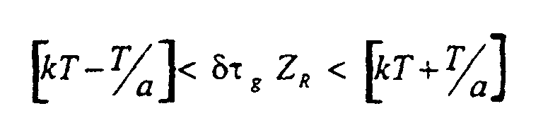
- the distance Z R between modulators will be chosen such that the difference in group time ⁇ g satisfies the condition where k is integer, a ⁇ 4, and T is the bit time (for Z R in km, dt g in ps.km -1 ).
- This constraint makes it possible to obtain an approximate synchronization between the two WDM channels having the wavelengths ⁇ 1 and ⁇ 2 .
- Better synchronization can be achieved by reducing the width of the time window (i.e., by increasing a), until the desired degree of synchronization is achieved.
- Figure 1 shows schematically an example of a Optical fiber transmission system capable of transmit and regenerate a WDM optical signal formed of solitons.
- This system comprises an optical fiber F, a optical transmitter E, at least one regeneration device RG, a plurality of line optical amplifiers G1, G2 ... Gk ..., a plurality of corrugated filters FC1, FC2 ... FCk ..., and an optical receiver R.
- the optical transmitter E comprises a plurality of optical sources capable of emitting solitons having respective frequencies ⁇ 1, ⁇ 2, ... ⁇ n and a multiplexer M for introducing said solitons onto the fiber optic F.
- the receiver comprises a demultiplexer D and a plurality of detectors optics able to receive respectively the solitons having frequencies ⁇ 1, ⁇ 2, ... ⁇ n.
- Optical amplifiers are distributed, preferably regularly, along of the line to compensate for the attenuations suffered by solitons. These optical amplifiers can, so classic, be of EDFA type (for Erbium Doped Fiber Amplify).
- the fluted filters FC1, FC2 ... FCk ... are disposed downstream of the optical amplifiers G1, G2, ...; reduce the temporal width of solitons and thereby temporal jitter.
- fluted filter is meant a filter bandpass that passes a plurality of bands narrow with different center frequencies, corresponding to the wavelengths of the different channels of the WDM system multiplexed in wavelength.
- FIG. 1 schematically illustrates a device for regeneration according to the invention.
- This regeneration device RG comprises a synchronization means 2 and a modulator 4.
- the modulator 4 is a known modulator, and used to regenerate a single-frequency soliton type signal, that is to say non-WDM.
- a modulator is described in particular in the article by Nakazawa et al. cited above. It comprises a MOD optical modulator, for example of the LiNO 3 type, for performing the synchronous modulation of solitons, which is controlled by an electronic control signal produced by a clock circuit from the on-line soliton signal.
- the clock recovering means comprises an optical coupler C3 for extracting a portion of the optical signal, a clock extraction circuit CLKX, a delay line for providing an LED delay, and a GM amplifier for providing the control power required to operate the modulator MOD in LiNO 3 .
- the modulation means may comprise devices Birefringent polarization control PC. Such devices can also be provided after the filters fluted ( Figure 1).
- a currently preferred synchronization means is shown schematically in Figure 3. It includes a Optical circulator 6 with three ports P1, P2, P3, one line optical comprising an optical fiber 8 and m filters photorefractive FPR1, FPR2, ... FPRm reflective respectively at ⁇ 1, ⁇ 2, ... ⁇ m (m ⁇ n), and an optical coupler 20 intended to transmit the solitons emitted on the n-m other channels, and which are not reflected by the filters photorefractive, to the output port of the means of synchronization.
- the optical circulator is designed for transmit a received signal on its port P1 to its port P2, and a signal received on its port P2 to its port P3.
- the ports P1 and P3 respectively form the input and output synchronization means 2.
- the Soliton signal emitted in the frequency channel ⁇ i (1 i i n n) arrives on port P1, is transmitted to port P2, goes through the fiber 8 to the FPRi filter, where it is reflected to the circulator 6, and is finally transmitted to the port P3.
- the relative position of the photoreflector filters is chosen to compensate for delays between channel signals 1 to m with respect to channel signals m + 1 to n, the latter being naturally synchronized (the modulator is placed where these channels are Synchronous). This delay can be determined in the way next.
- the integer N k1 represents the maximum number of bit times included in the delay between channel n and channel k. In fact, the quantity that matters is not the accumulated delay between two individual bits belonging to the channels n and k, but rather the relative delay between the corresponding time windows.
- Photorefractive filters are advantageously made in the form of BRAGG photo-inscribed filters directly on the fiber. They offer the benefit of a rate of high extinction and allow to define in a very specifies the delay of each channel.
- FIG. 4 Another embodiment of the synchronization means is shown in FIG. 4. It comprises a demultiplexer 22 with an input and m + 1 outputs, a set of m + 1 lines in parallel, and a multiplexer 24 with m + 1 inputs and output.
- a line 26 associated with all naturally synchronized channels has no optical delay line
- the other m lines are each associated with one of the other channels and each comprise a delay line.
- optical ⁇ i (1 ⁇ i ⁇ m) introduces an optical delay such that all the n channels are synchronized at the output of the synchronization means.
- FIG. 5 Another alternative embodiment of the synchronization means is shown in FIG. 5. It comprises a splitter 28 with an input and m + 1 outputs, a set of m + 1 lines in parallel, and a concentrator 30 with m + 1 inputs and output.
- a line 32 is associated with all the naturally synchronized channels and has a corrugated filter 34 correpondant these channels, and a set of m lines which are each associated with a channel and which each comprise a line optical delay such that all the n channels are synchronized at the output of the synchronization means.
- the filter 16i (1 ⁇ i ⁇ m) of the line i and the delay ⁇ i introduced by the delay line portion of the line i are chosen respectively to let paseer the solitons emitted on the channel i and to delay said solitons d a delay ⁇ i such that the solitons transmitted on line i are synchronous at the output of the concentrator with the solitons transmitted on line 32.
- a selective delay per channel can be obtained by using a dispersion-compensated optical fiber or an optical fiber comprising a chirped photorefractive filter (The term "chirped”, well known to those skilled in the art, derives of the Anglo-Saxon term “chirp” used to designate a medium of transmission in which the low frequencies are propagate faster than high frequencies).
- optical coupler used for recover the clock signal
- it can be placed on the transmission line, as shown in Figure 2, but that it could also be placed on the optical fiber 8 (Figure 3), or on one of the m + 1 parallel lines ( Figure 4) or ( Figure 5), or in one another point of the synchronization means.
Landscapes
- Engineering & Computer Science (AREA)
- Computer Networks & Wireless Communication (AREA)
- Signal Processing (AREA)
- Physics & Mathematics (AREA)
- Electromagnetism (AREA)
- Optical Communication System (AREA)
Description
L'invention concerne le domaine de télécommunications sur fibre optique, et plus particulièrement des télécommunications sur des longues distances. Il est connu, pour des liaisons très longues distances à fibre optique, tel que des liaisons transocéaniques, d'utiliser un signal de type dit "soliton" ayant des propriétés spectrales particulières qui permettent au signal de se propager sur la fibre dispersive sans dispersion chromatique appréciable, c'est-à-dire que l'on utilise la dépendance de l'indice de réfraction sur l'intensité du signal pour contrebalancer la dispersion chromatique ou vice-versa. La forme spectrale du signal est préservée malgré les effets de la distance de propagation, qui se résument ainsi principalement à des pertes de ligne. Ces pertes de ligne peuvent être compensées par une amplification optique en ligne, par exemple à l'aide d'un amplificateur à fibre dopée Erbium, ou "EDFA" en anglais.The invention relates to the field of telecommunications on optical fiber, and more particularly telecommunications over long distances. He is known, for very long fiber optic links, such as transoceanic links, to use a signal of the so-called "soliton" type having spectral properties particulars that allow the signal to propagate on the dispersive fiber without appreciable chromatic dispersion, that is, we use the dependence of the index of refraction on signal intensity to counterbalance the chromatic dispersion or vice versa. The spectral form of the signal is preserved despite the effects of the distance of propagation, which can be summarized mainly line losses. These line losses can be compensated by optical amplification in line, by example using an Erbium doped fiber amplifier, or "EDFA" in English.
Pour la transmission par solitons avec amplification
en ligne (EDFA) les problèmes qui restent à résoudre sont
connus :
Une solution à ce problème est avancée dans EP-A-576 208. Selon ce document, l'insertion d'une pluralité de filtres dont la fréquence centrale varie le long d'une liaison de transmission de signaux de type soliton, permet l'amplification périodique des solitons sans l'amplification exponentielle du bruit d'émission spontanée. Il n'y a pas de régénération des solitons dans ce système. Selon ce document, un avantage d'un tel système est sa compatibilité avec des transmissions multi-longueur d'ondes (WDM en anglais).A solution to this problem is advanced in EP-A-576 208. According to this document, the insertion of a plurality of filters whose center frequency varies along a soliton-type signal transmission link, allows periodic amplification of solitons without amplification exponential of spontaneous emission noise. There's no soliton regeneration in this system. According to this document, an advantage of such a system is its compatibility with multi-wavelength transmissions (WDM in English).
La modulation synchrone pour la régénération de solitons en ligne est décrite dans le document Elect. Lett., 27(14), p. 1270-72, 4 July 1991, Nakazawa et al. : "10 Gbit/s Soliton Data Transmission over One Million Kilometres".Synchronous modulation for on-line soliton regeneration is described in Elect. Lett., 27 (14), p. 1270-72, July 4, 1991, Nakazawa et al. : "10 Gbps Soliton Data Transmission Over One Million Kilometers".
Ce document enseigne l'utilisation d'un modulateur optique en LiNO3 pour effectuer la modulation synchrone des solitons, avec un signal d'horloge engendré à partir de la même horloge que celle utilisée pour la source de solitons. La simulation d'une liaison très longue distance a été faite sur une boucle de fibre de 500 km, avec un amplificateur optique à fibre dopée Erbium tous les 50 km et une régénération à chaque tour de la boucle. A cause de la dispersion de la fibre de transmission soliton, qui varie entre -0.7 à -2.2 ps/km/nm, avec une moyenne de -1.5 ps/km/nm, le temps de trajet pour faire un tour de la boucle dépend de la longueur d'onde du soliton. Pour cette raison, un tel système est incompatible avec une transmission WDM, comme souligné dans le document EP-A-0 576 208 évoqué plus haut (cf. page 2, lignes 21-24.).This document teaches the use of a LiNO 3 optical modulator for performing synchronous modulation of solitons, with a clock signal generated from the same clock used for the soliton source. Simulation of a very long distance link was done on a 500 km fiber loop, with an Erbium doped fiber optical amplifier every 50 km and a regeneration at each turn of the loop. Due to the dispersion of the soliton transmission fiber, which varies between -0.7 and -2.2 ps / km / nm, with an average of -1.5 ps / km / nm, the travel time to go around the loop depends on of the soliton wavelength. For this reason, such a system is incompatible with a WDM transmission, as pointed out in EP-A-0 576 208 mentioned above (see page 2, lines 21-24.).
D'autres documents de l'état de la technique se rapportent aux liaisons optiques de type WDM.Other documents of the state of the art are relate to optical links of WDM type.
Par exemple, le document Journal of Lightwave Tech., 9(3), pp. 362-367, March 1991, L.F. Mollenauer et al. : "Wavelength Division Multiplexing with Solitons in Ultra-Long Distance Transmission Using Lumped Amplifiers" propose un système de transmission de solitons WDM avec amplification optique périodique, pour des distances transocéaniques (9000 km). L'enseignement de ce document concerne principalement les collisions entre des solitons ayant des longueurs d'onde différentes. Ce document donne des valeurs typiques de différents paramètres pour une telle liaison afin de limiter la gigue de Gordon-Haus introduite par interaction entre les canaux adjacents. Toutefois, dans tous les cas considérés dans ce document, la synchronicité de l'arrivée des solitons à la fin de la liaison n'est ni prévue, ni requise.For example, the document Journal of Lightwave Tech., 9 (3), pp. 362-367, March 1991, LF Mollenauer et al. : "Wavelength Division Multiplexing with Solitons in Ultra-Long Distance Transmission Using Lumped Amplifiers" proposes a WDM soliton transmission system with periodic optical amplification, for transoceanic distances (9000 km). The teaching of this document mainly concerns collisions between solitons with different wavelengths. This document gives typical values of different parameters for such a link in order to limit Gordon-Haus jitter introduced by interaction between adjacent channels. However, in all the cases considered in this document, the synchronicity of the arrival of the solitons at the end of the connection is neither planned nor required.
Les différents aspects de la gestion des dispersions dans des systèmes WDM non régénérés est également considéré dans le document Proc. Int'l. Symposium on physics and applications of Optical Solitons in fibers, Kyoto, Japan, pp. 1-12, Nov. 14-17, 1995, S. Kumar et al. : "Dispersion managements on soliton transmission in fibers with lumped amplifiers" (cf. dernier chapitre de ce document).The different aspects of dispersions management in unregenerated WDM systems is also considered in the document Proc. Int'l. Symposium on physics and Applications of Optical Solids in Fiber, Kyoto, Japan, pp. 1-12, Nov. 14-17, 1995, S. Kumar et al. : "Dispersion managements on soliton transmission in fibers with lumped amplifiers "(see last chapter of this document).
Ainsi, à la lecture des documents de l'art antérieur, on constate que liaisons optiques à plusieurs canaux multiplexés en longueur d'onde (WDM) ne permettent pas une régénération des solitons puisqu'il n'y a pas de synchronicité entre les canaux. La question de la régénération synchrone est donc, dans cette optique, sans objet.Thus, on reading the documents of the prior art, we see that optical links to several channels wavelength multiplexing (WDM) do not allow a regeneration of solitons since there is no synchronicity between the channels. The question of Synchronous regeneration is therefore, in this perspective, without object.
Pour cette raison, il n'apparaít pas possible, d'après les préjugés bien établis de l'homme de l'art, d'envisager des liaisons optiques WDM très haut débit, très longues distances, via solitons multiplexés en longueur d'onde et avec régénération pour éliminer la gigue Gordon-Haus et pour garder la forme spectrale optimale des solitons.For this reason, it did not seem possible, according to the well-established prejudices of those skilled in the art, to consider Very high speed, very long WDM optical links distances, via multiplexed wavelength solitons and with regeneration to eliminate Gordon-Haus jitter and to keep the optimum spectral shape of the solitons.
Dans le document PAJ vol. 097 no. 003, 31 mars 1997 l'ensemble des canaux sont resynchronisés entre eux en entrée du modulateur.In the document PAJ vol. 097 no. 003, March 31, 1997 all channels are resynchronized between them at the input of modulator.
L'invention a pour but de pallier les inconvénients de l'art antérieur.The object of the invention is to overcome the drawbacks of the prior art.
A cette fin, l'invention a pour objet un dispositif de régénération d'un signal optique ayant la forme d'un train de bits représentés par des solitons définis notamment par une longueur d'onde de propagation et un rythme de bits ledit dispositif comprenant un circuit de récupération d'horloge pour extraire un signal d'horloge dudit signal optique, un modulateur optique pour régénérer lesdits solitons et un filtre spectral et étant caractérisé en ce qu'il comporte en amont du modulateur un moyen de synchronisation pour des solitons émis sur n (n>1) canaux ayant des longueurs d'onde respectives différentes, lesdits canaux et lesdites longueurs d'onde différentes étant associés à des temps de groupe différents, ledit moyen de synchronisation comportant m (l≤m<n) lignes à retard optiques, le retard τi (l≤i≤m) pour la ligne i étant choisi de manière à compenser les différences entre les temps de groupe associés aux différents canaux.To this end, the subject of the invention is a device for regenerating an optical signal in the form of a bit stream represented by solitons defined in particular by a propagation wavelength and a bit rate, said device comprising a clock recovery circuit for extracting a clock signal from said optical signal, an optical modulator for regenerating said solitons and a spectral filter and characterized in that it comprises upstream of the modulator synchronization means for solitons emitted on n (n> 1) channels having different respective wavelengths, said channels and said different wavelengths being associated with different group times, said timing means having m (l≤m <n) lines at optical delay, the delay τ i (l≤i≤m) for the line i being chosen so as to compensate for the differences between the group times associated with the different channels.
Selon un mode de réalisation avantageux, le moyen de synchronisation comporte m lignes à retard optiques, avec m<n, le retard τi (1≤i<m) pour le canal i étant choisi de manière à compenser les différences de temps de groupe entre m canaux, et au moins une ligne sans retard optique pour les n-m autres canaux.According to an advantageous embodiment, the synchronization means comprises m optical delay lines, with m <n, the delay τ i (1 i i <m) for the channel i being chosen so as to compensate for group time differences. between m channels, and at least one line without optical delay for the other nm channels.
En particulier, le moyen de synchronisation peut comprendre une seule ligne sans retard optique, ladite ligne sans retard optique étant conçue pour recevoir des solitons multiplexés émis par une pluralité de canaux.In particular, the synchronization means can to understand a single line without optical delay, said line without optical delay being adapted to receive solitons multiplexed transmitted by a plurality of channels.
Selon un premier mode de réalisation, actuellement préféré, le moyen de synchronisation comprend une ligne optique équipée d'une pluralité de filtres photoréfractifs en série, la fréquence de chaque filtre étant associée à celle d'un canal et la position respective de chaque filtre i (l≤i≤m) étant choisie de manière à produire ledit retard τi pour les solitons émis sur le canal i; et un moyen de contrôle pour émettre vers ladite ligne optique les solitons reçus par le moyen de synchronisation et vers un port de sortie du moyen de synchronisation les solitons réfléchis par les filtres de ladite ligne optique; et un coupleur optique pour transmettre les solitons émis sur les canaux qui ne sont pas associés à un filtre vers le port de sortie du moyen de synchronisation. Dans ce mode de réalisation, le moyen de contrôle est avantageusement un circulateur optique à trois ports.According to a first embodiment, currently preferred, the synchronization means comprises an optical line equipped with a plurality of photorefractive filters in series, the frequency of each filter being associated with that of a channel and the respective position of each filter i (l≤i≤m) being chosen so as to produce said delay τ i for the solitons emitted on channel i; and control means for transmitting to said optical line the solitons received by the synchronizing means and to an output port of the synchronization means the solitons reflected by the filters of said optical line; and an optical coupler for transmitting the solitons transmitted on the channels which are not associated with a filter to the output port of the synchronization means. In this embodiment, the control means is advantageously a three-port optical circulator.
Selon un deuxième mode de réalisation de l'invention, le moyen de synchronisation comprend un démultiplexeur; un ensemble de m lignes en parallèle comportant chacune un tronçon de ligne à retard optique; un multiplexeur; au moins une ligne sans retard optique disposée entre le démultiplexeur et le multiplexeur.According to a second embodiment of the invention, the synchronization means comprises a demultiplexer; a set of m parallel lines each comprising a section of optical delay line; a multiplexer; at least a line without optical delay arranged between the demultiplexer and the multiplexer.
Selon un troisième mode de réalisation de l'invention, le moyen de synchronisation comprend un diviseur; un ensemble de m lignes en parallèle comportant chacune un filtre pour sélectionner un canal et un tronçon de ligne à retard optique; un concentrateur; et au moins une ligne sans retard optique entre le diviseur et le concentrateur, ladite ligne sans retard comprenant un filtre pour sélectionner au moins un canal.According to a third embodiment of the invention, the synchronization means comprises a divider; a set of m parallel lines each comprising a filter to select a channel and a line section to optical delay; a concentrator; and at least one line without optical delay between the divider and the concentrator, said line without delay including a filter to select at least one channel.
L'invention a également pour objet un système de transmission optique de signaux ayant chacun la forme d'un train de bits représentés par des solitons, qui sont définis notamment par une longueur d'onde de propagation et un rythme de bits, ledit système de transmission comprenant au moins un émetteur et un récepteur reliés par une fibre optique, ledit système comprenant au moins un dispositif de régénération optique selon l'invention.The subject of the invention is also a system of optical transmission of signals each having the shape of a bitstream represented by solitons, which are defined in particular by a propagation wavelength and a bit rate, said transmission system comprising at least less a transmitter and a receiver connected by a fiber optical system, said system comprising at least one optical regeneration according to the invention.
Avantageusement, dans le cas d'un tel système de
transmission optique, chaque dispositif de régénération est
placé à une distance ZR, après ledit émetteur ou le
dispositif de régénération qui le précède, choisie telle que
son produit avec la différence de temps d'arrivée δτg=τg(λ1) -
τg(λℓ) satisfasse la condition

De manière particulièrement avantageuse, le circuit de récupération d'horloge extrait du signal optique un signal de longueur d'onde λk comprise entre les longueurs d'onde λ1 et λℓ; tel que τg(λk).ZR = kT. In a particularly advantageous manner, the clock recovery circuit extracts from the optical signal a signal of wavelength λ k lying between the wavelengths λ 1 and λ ℓ ; such that τ g (λ k ) .Z R = kT.
Les caractéristiques et avantages de l'invention ressortiront mieux de la description, qui va suivre, de modes de réalisation donnés à titre illustratif, mais non limitatif, en référence aux dessins annexés, sur lesquels :
- la figure 1 illustre schématiquement un système de transmission optique sur fibre optique selon l'invention,
- la figure 2 montre schématiquement un dispositif de régénération selon l'invention,
- la figure 3 illustre un premier mode de réalisation du moyen de synchronisation selon l'invention, conçu pour resynchroniser les solitons émis par les n canaux d'une liaison WDM à n canaux
- la figure 4 illustre un deuxième mode de réalisation du moyen de synchronisation selon l'invention, conçu pour resynchroniser les solitons émis par les n canaux d'une liaison WDM à n canaux, et
- la figure 5 illustre un troisième mode de réalisation du moyen de synchronisation selon l'invention, conçu pour resynchroniser les solitons émis par les n canaux d'une liaison WDM à n canaux.
- FIG. 1 diagrammatically illustrates an optical fiber transmission system according to the invention,
- FIG. 2 schematically shows a regeneration device according to the invention,
- FIG. 3 illustrates a first embodiment of the synchronization means according to the invention, designed to resynchronize the solitons emitted by the n channels of an N-channel WDM link.
- FIG. 4 illustrates a second embodiment of the synchronization means according to the invention, designed to resynchronize the solitons emitted by the n channels of an N-channel WDM link, and
- FIG. 5 illustrates a third embodiment of the synchronization means according to the invention, designed to resynchronize the solitons emitted by the n channels of an N-channel WDM link.
Sur toutes les figures, les mêmes références numériques se réfèrent aux mêmes éléments, et l'échelle n'est pas toujours respectée pour des raisons de clarté.In all the figures, the same references Numbers refer to the same elements, and the scale is not always respected for the sake of clarity.
Une solution pour résoudre le problème de la synchronicité de solitons émis sur différents canaux est décrite dans la demande de brevet français n°9600732 déposée le 23/01/1996 au nom de Alcatel Submarine Networks et intitulée "Méthode et dispositif de régénération en ligne d'un signal transmis par solitons multiplexés en longueur d'onde via la modulation synchrone et système de télécommunications optiques utilisant la méthode".A solution to solve the problem of synchronicity of solitons emitted on different channels is described in French Patent Application No. 9600732 filed on 23/01/1996 in the name of Alcatel Submarine Networks and entitled "Method and device for online regeneration of a signal transmitted by solitons multiplexed in length waveform via synchronous modulation and optical telecommunications using the method ".
On résume ci-après le principe de synchronisation développé dans cette demande de brevet antérieure, dans la mesure nécessaire à la compréhension de la présence invnetion. Le lecteur est invité à se référer à cette demande de brevet antérieure pour de plus amples détails.We summarize below the principle of synchronization developed in this earlier patent application, in the necessary measure to understand the presence invnetion. The reader is invited to refer to this prior patent application for further details.
Dans cette demande de brevet antérieure, il est proposé de tenir compte de la longueur du chemin optique parcouru par les solitons en fonction de leurs longueurs d'onde, de manière à ce que les solitons soit synchronisés, au moins approximativement, à l'endroit même où est positionné le modulateur.In this prior patent application, it is proposed to take into account the length of the optical path traveled by solitons according to their lengths wave, so that the solitons are synchronized, at least approximately, at the very place where is positioned the modulator.
En effet, il est remarqué que les signaux de solitons émis sur les différents canaux, bien que désynchronisés par la dispersion chromatique lors de leur propagation sur la fibre optique, comportent tous des signaux périodiques, avec des rythmes bit identiques à l'émission. Il en résulte des "collisions" entre des solitons de canaux voisins le long de la ligne de transmission (voir description théorique dans l'article de Mollenauer et al. déjà cité). De ce fait, et tenant compte des décalages fréquentiels entre les différents canaux, tous les canaux se retrouveront synchronisés entre eux à certains points espacés régulièrement le long de la ligne. Il est alors proposé de calculer cet espacement et de placer les régénérateurs à l'un de ces points de synchronisation, afin d'effectuer la modulation synchrone avec un seul modulateur et sans démultiplexage.Indeed, it is noticed that the signals of solitons transmitted on the various channels, although desynchronised by chromatic dispersion during their propagation on the optical fiber, all have periodic signals, with bit rates identical to the emission. This results in "collisions" between solitons of neighboring channels along the transmission line (see theoretical description in the article by Mollenauer et al. already cited). Because of this, and taking account of the frequency differences between different channels, all channels will end up synchronized with each other at certain spaced points regularly along the line. It is then proposed to calculate this spacing and place the regenerators at one of these synchronization points, in order to perform the synchronous modulation with a single modulator and without demultiplexing.
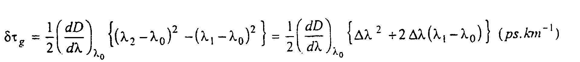
Par exemple, pour deux canaux transmis à λ1 et λ2,
avec λ0 la longueur d'onde de dispersion nulle, et Dl = λ2 -
λ1, la différence de temps d'arrivée au modulateur résulte
de la différence de temps de groupe δτg =τg(λ2) - τg(λ1),
La méthode proposée consiste ainsi à utiliser un seul
modulateur synchrone pour tous les canaux WDM, en
choisissant soigneusement la distance entre l'émetteur et le
premier modulateur, ou entre modulateurs successifs, par
rapport a l'espacement des canaux et la dispersion
chromatique de la fibre, afin de retrouver tous les canaux
synchronisés lors du passage dans chaque modulateur. En
pratique, la distance ZR entre modulateurs sera choisie
telle que la différence de temps de groupe δτg satisfasse la
condition
La technique proposée dans cette demande de brevet antérieure est mise en oeuvre dans le cadre de la présente invention. Plus précisément, dans le cas d'un système de transmission à n canaux WDM, on prévoit de placer un modulateur à l'endroit ou un sous-ensemble de n-m (m<n) canaux sont naturellement synchronisés, selon la technique décrite dans la demande de brevet antérieure, et de synchroniser les m canaux restants sur ce sous-ensemble de canaux.The technique proposed in this patent application prior is implemented in the context of this invention. More specifically, in the case of a system of transmission to n WDM channels, it is planned to place a modulator at the place or subset of n-m (m <n) channels are naturally synchronized, according to the technique described in the earlier patent application, and synchronize the remaining m channels on this subset of canals.
Cette combinaison de deux techniques de synchronisation présente des avantages évidents : la contrainte sur la position du modulateur est moins forte que dans le cas de la demande de brevet antérieure puisqu'il n'est plus requis que tous les canaux soient naturellement synchronisés (lorsque le nombre de canaux WDM augmente, la distance ZR entre les deux points successifs où tous les canaux sont naturellement synchronisés augmente; par suite l'atténuation, la dispersion, etc ... des signaux augmentent) et le moyen de synchronisation est plus simple puisqu'il ne doit traiter qu'une partie des canaux.This combination of two synchronization techniques has obvious advantages: the constraint on the position of the modulator is less strong than in the case of the earlier patent application since it is no longer required that all the channels are naturally synchronized (when the number of WDM channels increases, the distance Z R between the two successive points where all the channels are naturally synchronized increases, as a result the attenuation, the dispersion, etc ... of the signals increase) and the synchronization means is simpler because it has to treat only a part of the channels.
La figure 1 montre schématiquement un exemple d'un système de transmissions optiques sur fibre optique apte à transmettre et régénérer un signal optique WDM formé de solitons. Ce système comprend une fibre optique F, un émetteur optique E, au moins un dispositif de régénération RG, une pluralité d'amplificateurs optiques de ligne G1, G2 ... Gk ..., une pluralité de filtres cannelés FC1, FC2 ... FCk ..., et un récepteur optique R. L'émetteur optique E comprend une pluralité de sources optiques aptes à émettre des solitons ayant des fréquences respectives λ1, λ2, ... λn et un multiplexeur M pour introduire lesdits solitons sur la fibre optique F. De manière symétrique, le récepteur comprend un démultiplexeur D et une pluralité de détecteurs optiques aptes à recevoir respectivement les solitons ayant des fréquences λ1, λ2, ... λn. Les amplificateurs optiques sont répartis, de préférence de manière régulière, le long de la ligne pour compenser les atténuations subies par les solitons. Ces amplificateurs optiques peuvent, de façon classique, être de type EDFA (pour Erbium Doped Fibre Amplifier). Les filtres cannelés FC1, FC2 ... FCk ... sont disposés en aval des amplificateurs optiques G1, G2, ...;ils réduisent la largeur temporelle des solitons et, par là même la gigue temporelle. Par filtre cannelé, on entend un filtre passe-bande qui laisse passer une pluralité des bandes étroites ayant des fréquences centrales différentes, correspondant aux longueurs d'ondes des différents canaux du système WDM multiplexé en longueur d'onde.Figure 1 shows schematically an example of a Optical fiber transmission system capable of transmit and regenerate a WDM optical signal formed of solitons. This system comprises an optical fiber F, a optical transmitter E, at least one regeneration device RG, a plurality of line optical amplifiers G1, G2 ... Gk ..., a plurality of corrugated filters FC1, FC2 ... FCk ..., and an optical receiver R. The optical transmitter E comprises a plurality of optical sources capable of emitting solitons having respective frequencies λ1, λ2, ... λn and a multiplexer M for introducing said solitons onto the fiber optic F. Symmetrically, the receiver comprises a demultiplexer D and a plurality of detectors optics able to receive respectively the solitons having frequencies λ1, λ2, ... λn. Optical amplifiers are distributed, preferably regularly, along of the line to compensate for the attenuations suffered by solitons. These optical amplifiers can, so classic, be of EDFA type (for Erbium Doped Fiber Amplify). The fluted filters FC1, FC2 ... FCk ... are disposed downstream of the optical amplifiers G1, G2, ...; reduce the temporal width of solitons and thereby temporal jitter. By fluted filter is meant a filter bandpass that passes a plurality of bands narrow with different center frequencies, corresponding to the wavelengths of the different channels of the WDM system multiplexed in wavelength.
Un système de transmission optique tel que représenté sur la figure 1, mais dépourvu de dispositifs de régénération en ligne, fait partie de l'état de la technique; cf. l'article de L.F. Mollenauer et al. cité plus haut.An optical transmission system as shown in Figure 1, but lacking devices for regeneration online, is part of the state of the technical; cf. the article by L.F. Mollenauer et al. cited more high.
La présente invention tient précisément dans le fait de régénérer en ligne un signal optique de type soliton WDM. La figure 2 illustre schématiquement un dispositif de régénération selon l'invention.The present invention is precisely in the fact to regenerate online a WDM soliton type optical signal. Figure 2 schematically illustrates a device for regeneration according to the invention.
Ce dispositif de régénération RG comprend un moyen de synchronisation 2 et un modulateur 4. Le modulateur 4 est un modulateur connu, et utilisé pour régénérer un signal de type soliton à fréquence unique, c'est-à-dire non-WDM. Un tel modulateur est décrit notamment dans l'article de Nakazawa et al. cité plus haut. Il comprend un modulateur optique MOD, par exemple de type LiNO3, pour effectuer la modulation synchrone des solitons, qui est commandé par un signal électronique de commande produit par un circuit d'horloge à partir du signal de solitons en ligne. Les moyens de récupération d'horloge comprennent un coupleur optique C3 pour l'extraction d'une partie du signal optique, un circuit d'extraction d'horloge CLKX, une ligne à retard pour fournir un délai DEL, et un amplificateur GM pour fournir la puissance de commande nécessaire pour faire fonctionner le modulateur MOD en LiNO3.This regeneration device RG comprises a synchronization means 2 and a modulator 4. The modulator 4 is a known modulator, and used to regenerate a single-frequency soliton type signal, that is to say non-WDM. Such a modulator is described in particular in the article by Nakazawa et al. cited above. It comprises a MOD optical modulator, for example of the LiNO 3 type, for performing the synchronous modulation of solitons, which is controlled by an electronic control signal produced by a clock circuit from the on-line soliton signal. The clock recovering means comprises an optical coupler C3 for extracting a portion of the optical signal, a clock extraction circuit CLKX, a delay line for providing an LED delay, and a GM amplifier for providing the control power required to operate the modulator MOD in LiNO 3 .
Le moyen de modulation peut comprendre des dispositifs de contrôle de polarisation biréfringents PC. De tels dispositifs peuvent également être prévus après les filtres cannelés (figure 1).The modulation means may comprise devices Birefringent polarization control PC. Such devices can also be provided after the filters fluted (Figure 1).
Pour permettre la modulation synchrone simultanée d'une pluralité de signaux soliton multiplexés en longueur d'onde, donc ayant des longueurs d'onde différentes, des vitesses de groupe différentes, et donc des temps de trajet différents, il faut que les solitons émis dans les différents canaux soient synchrones.To enable simultaneous synchronous modulation a plurality of multiplexed soliton signals in length waveform, therefore having different wavelengths, different group speeds, and therefore travel times different, it is necessary that the solitons emitted in different channels are synchronous.
Différents modes de réalisation d'un dispositif de régénération conforme à l'invention vont maintenant être décrits.Different embodiments of a device for regeneration according to the invention will now be described.
Un moyen de synchronisation actuellement préféré est
représenté schématiquement sur la figure 3. Il comprend un
circulateur optique 6 à trois ports P1, P2, P3, une ligne
optique comportant une fibre optique 8 et m filtres
photoréfractifs FPR1, FPR2, ... FPRm réfléchissants
respectivement à λ1, λ2, ... λm (m<n), et un coupleur optique
20 destiné à transmettre les solitons émis sur les n-m
autres canaux, et qui ne sont pas réfléchis par les filtres
photoréfractifs, vers le port de sortie du moyen de
synchronisation. Le circulateur optique est conçu pour
transmettre un signal reçu sur son port P1 vers son port P2,
et un signal reçu sur son port P2 vers son port P3. Les
ports P1 et P3 forment respectivement les entrée et sortie
du moyen de synchronisation 2. On comprend donc que le
signal soliton émis dans le canal de fréquence λi (1≤i≤n)
arrive sur le port P1, est transmis vers le port P2,
parcourt la fibre 8 jusqu'au filtre FPRi, où il est réfléchi
vers le circulateur 6, et est finalement transmis vers le
port P3. La position relative des filtres photoréflecteurs
est choisie de manière à compenser les retards entre les
signaux des canaux 1 à m par rapport aux signaux des canaux
m+1 à n, ces derniers étant naturellement synchronisés (le
modulateur est placé à l'endroit où ces canaux sont
synchrones). Ce retard peut être déterminé de la manière
suivante.A currently preferred synchronization means is
shown schematically in Figure 3. It includes a
Optical circulator 6 with three ports P1, P2, P3, one line
optical comprising an optical fiber 8 and m filters
photorefractive FPR1, FPR2, ... FPRm reflective
respectively at λ1, λ2, ... λm (m <n), and an
Pour chaque canal (longueur d'onde λ), le temps de
groupe (par km) est donné par la relation :

Les deux relations précédentes concernent le cas où la
pente de dispersion (dD/dλ)λ0 est non nulle. Il est possible,
voire avantageux, cependant, de réaliser un système où la
pente de dispersion est périodiquement corrigée (compensée)
par insertion de courts tronçons de fibre de
caractéristiques opposées, ou bien de réaliser une fibre de
transmission à pente nulle ou aplatie. Que le système soit à
pente de dispersion compensée ou effectivement nulle, le
temps de groupe (par km) est alors donné par la relation :
Si Tbit représente le temps bit (ou la période de
modulation synchrone), on peut définir un nombre Nk1 (pour
k=1 ... n) comme étant le nombre entier vérifiant la relation
pour le canal k : Nk1 Tbit ≤ δτ ≤ (Nk1+1) Tbit, soit Nk1 =
E (δτk1/Tbit) où E (x) représente la partie entière de
l'argument x. L'entier Nk1 représente le nombre de temps bit
maximum inclut dans le retard entre le canal n et le canal
k. En fait, la quantité qui importe n'est pas le retard
accumulé entre deux bits individuels appartenant aux canaux
n et k, mais plutôt le retard relatif entre les fenêtres
temporelles correspondantes. L'avance de la fenêtre k sur la
fenêtre n est ainsi donnée par Δτk1(avance) = δτk1 - Nk1 Tbit
et le retard de la fenêtre k sur la fenêtre n par :

Notons que pour des considérations pratiques, on peut rajouter à ce retard une quantité supplémentaire égale à un nombre entier de temps bit Tbit. Quand le retard est introduit dans chaque canal, tous les signaux se retrouvent synchrones en entrée du modulateur.Note that for practical considerations, we can add to this delay an additional amount equal to an integer number of times bit T bit . When the delay is introduced in each channel, all the signals are synchronous at the input of the modulator.
Les filtres photoréfractifs sont avantageusement réalisés sous forme de filtres de BRAGG photoinscrits directement sur la fibre. Ils offrent l'avantage d'un taux d'extinction élevé et permettent de définir de manière très précise le retard de chaque canal.Photorefractive filters are advantageously made in the form of BRAGG photo-inscribed filters directly on the fiber. They offer the benefit of a rate of high extinction and allow to define in a very specifies the delay of each channel.
Un autre mode de réalisation du moyen de
synchronisation est représenté sur la figure 4. Il comprend
un démultiplexeur 22 à une entrée et m+1 sorties, un
ensemble de m+1 lignes en parallèle, et un multiplexeur 24 à
m+1 entrées et une sortie. Parmi l'ensemble de lignes en
parallèle, une ligne 26 associée à tous les canaux
naturellement synchronisés ne comporte pas de ligne à retard
optique, et les m autres lignes sont associées chacune à
l'un des autres canaux et comportent chacune une ligne à
retard optique τi (1≤i≤m) introduit un retard optique tel
que l'ensemble des n canaux soient synchronisés en sortie du
moyen de synchronisation.Another embodiment of the synchronization means is shown in FIG. 4. It comprises a
Une autre variante de réalisation du moyen de
synchronisation est représenté sur la figure 5. Il comprend
un répartiteur 28 à une entrée et m+1 sorties, un ensemble
de m+1 lignes en parallèle, et un concentrateur 30 à m+1
entrées et une sortie. Parmi l'ensemble de lignes en
parallèle, une ligne 32 est associée à tous les canaux
naturellement synchronisés et comporte un filtre cannelé 34
correpondant à ces canaux, et un ensemble de m lignes qui
sont chacune associées à un canal et qui comportent chacune
une ligne à retard optique tel que l'ensemble des n canaux
soient synchronisés en sortie du moyen de synchronisation.
Ainsi le filtre 16i (1≤i≤m) de la ligne i et le retard τi
introduit par la portion de ligne à retard de la ligne i
sont choisis respectivement pour laisser paseer les solitons
émis sur le canal i et pour retarder lesdits solitons d'un
retard τi tel que les solitons transmis sur la ligne i
soient synchrones en sortie du concentrateur avec les
solitons transmis sur la ligne 32.Another alternative embodiment of the synchronization means is shown in FIG. 5. It comprises a
Le moyen de synchronisation représenté sur la figure 5 présente une meilleure extinction des canaux adjacents, par rapport au moyen de réalisation représenté sur la figure 4, mais ceci au prix d'une perte d'insertion augmentant en n2. Cette perte d'insertion reste cependant raisonnable, lorsque le nombre n de canaux est petit. Dans le cas d'une transmission à multiplexage en fréquence sur n=2 ou 3 canaux, le mode de réalisation de la figure 5 est actuellement préféré au mode de réalisation de la figure 4.The synchronization means shown in FIG. 5 has a better extinction of the adjacent channels, with respect to the embodiment represented in FIG. 4, but this at the cost of an insertion loss increasing in n 2 . This insertion loss remains reasonable, however, when the number n of channels is small. In the case of n = 2 or 3 channel frequency multiplex transmission, the embodiment of FIG. 5 is currently preferred to the embodiment of FIG. 4.
D'autres moyens de synchronisation que ceux décrits en référence aux figures 3 à 5 sont connus et peuvent être utilisés dans le cadre de la présente invention. Par exemple, un retard sélectif par canal peut être obtenu en utilisant une fibre optique à compensation de dispersion ou une fibre optique comportant un filtre photoréfractif chirpé (le terme "chirpé", bien connu de l'homme du métier, dérive du terme anglo-saxon "chirp" utilisé pour désigner un milieu de transmission dans lequel les basses fréquences se propagent plus vite que les hautes fréquences).Other means of synchronization than those described in 3 to 5 are known and can be used in the context of the present invention. By For example, a selective delay per channel can be obtained by using a dispersion-compensated optical fiber or an optical fiber comprising a chirped photorefractive filter (The term "chirped", well known to those skilled in the art, derives of the Anglo-Saxon term "chirp" used to designate a medium of transmission in which the low frequencies are propagate faster than high frequencies).
En ce qui concerne le coupleur optique utilisé pour récupérer le signal d'horloge, il convient de noter qu'il peut être placé sur la ligne de transmission, comme représenté sur la figure 2, mais qu'il pourrait aussi être placé sur la fibre optique 8 (figure 3), ou sur l'une des m+1 lignes parallèles (figure 4) ou (figure 5), ou en un autre point du moyen de synchronisation.With regard to the optical coupler used for recover the clock signal, it should be noted that it can be placed on the transmission line, as shown in Figure 2, but that it could also be placed on the optical fiber 8 (Figure 3), or on one of the m + 1 parallel lines (Figure 4) or (Figure 5), or in one another point of the synchronization means.
L'invention n'est pas limitée aux modes de réalisation représentés, mais englobe au contraire les moyens équivalents à ceux décrits et tous les modes de réalisation qui sont conformes aux revendications annexées.The invention is not limited to the embodiments represented, but on the contrary, equivalent to those described and all embodiments which are in accordance with the appended claims.
Claims (11)
- Apparatus for regenerating an optical signal in the form of a bit stream represented by solitons defined in particular by a propagation wavelength and a bit rate, said apparatus comprising a clock recovery circuit (C3, CLKX) for extracting a clock signal from said optical signal and an optical modulator (MOD) for regenerating said solitons, and being characterized in that it includes, upstream from the modulator, synchronization means (2) for synchronizing solitons emitted on n channels having respective different wavelengths, where n>1, said channels and said different wavelengths being associated with different group times, said synchronization means having m optical delay lines, where 1≤m<n, the delay τi for the line i, where 1≤i≤m, being selected in such a manner as to compensate for the differences between the group times associated with the various channels.
- Apparatus according to claim 1, characterized in that the synchronization means have m optical delay lines, where m<n, the delay τi for channel i, where 1≤i<m, being selected in such a manner as to compensate for the group time differences between m channels, and also have at least one line without optical delay for the n-m other channels.
- Apparatus according to claim 2, characterized in that the synchronization means comprise a single line without optical delay (26; 32), said line without optical delay being designed to receive multiplexed solitons emitted over a plurality of channels.
- Apparatus according to claim 1 or 2, characterized in that the synchronization means include an optical line (8) fitted with m photorefractive filters in series (FPR1, FPR2, ..., FPRm), the frequency of each filter being associated with the frequency of a respective channel, and the respective position of each filter i, where 1≤i≤m, being selected so as to produce said delay τi for the solitons emitted on channel i; control means (6) for applying the solitons received by the synchronization means to said optical line and for applying the solitons reflected by the filters of said optical line to an outlet port of the synchronization means; and an optical coupler (20) for conveying the solitons emitted on the n-m channels which are not associated with a filter to the outlet port of the synchronization means.
- Apparatus according to claim 4, characterized in that said control means (6) is a three-port optical circulator.
- Apparatus according to claim 1 or 2, characterized in that the synchronization means comprises a demultiplexer (22), a set of m lines in parallel, each including a length of optical delay line, a multiplexer (24), and at least one line (26) without optical delay disposed between the demultiplexer and the multiplexer.
- Apparatus according to claim 1 or 2, characterized in that the synchronization means comprise: a divider (28); a set of m lines in parallel each having a respective filter (161, ..., 16m) for selecting one channel, and a length of optical delay line; a concentrator (30); and at least one line (32) without optical delay between the divider (28) and the concentrator (30), said line without delay having a filter (34) for selecting at least one channel.
- Apparatus according to any one of claims 1 to 7, characterized in that it includes a channel filter (Fck) at the output from the synchronous modulator (MOD).
- An optical transmission system for conveying signals each of which is in the form of a bit stream represented by solitons, which solitons are defined in particular by a propagation wavelength and by a bit rate, said transmission system comprising at least an emitter (E) and a receiver (R) interconnected by an optical fiber (F), said system being characterized in that it includes at least one optical regenerator apparatus according to any one of claims 1 to 8.
- A system according to claim 9, characterized in that each regenerator apparatus is disposed at a distance ZR from said emitter or from the preceding regenerator apparatus, where the distance ZR is selected in such a manner that its product with the arrival time difference δτg = τg(λ1) - τg(λℓ) satisfies the following condition:where: k is an integer; a≥4; T is the bit time; ZR is in km; δτg is in ps.km-1; and λ1 and λℓ are the end wavelengths of the spectrum band defined by said subset of n-m channels.

- A system according to claim 10, characterized by a clock recovery circuit which extracts a signal of wavelength λk from the optical signal, where λk lies in the wavelength range λ1 to λℓ, such that τg(λk).ZR = kT.
Applications Claiming Priority (3)
| Application Number | Priority Date | Filing Date | Title |
|---|---|---|---|
| FR9701476A FR2759516B1 (en) | 1997-02-10 | 1997-02-10 | METHOD AND DEVICE FOR ONLINE REGENERATION OF A SIGNAL TRANSMITTED BY MULTIPLEX WAVELENGTH AND OPTICAL TELECOMMUNICATIONS SYSTEM INCLUDING SUCH A REGENERATION DEVICE |
| FR9701476 | 1997-02-10 | ||
| PCT/FR1998/000258 WO1998035459A1 (en) | 1997-02-10 | 1998-02-10 | Method and device for on-line regeneration of a signal transmitted by wavelength division multiplexed solitons and optical telecommunication system comprising such a regenerating device |
Publications (2)
| Publication Number | Publication Date |
|---|---|
| EP0897624A1 EP0897624A1 (en) | 1999-02-24 |
| EP0897624B1 true EP0897624B1 (en) | 2005-09-28 |
Family
ID=9503497
Family Applications (1)
| Application Number | Title | Priority Date | Filing Date |
|---|---|---|---|
| EP98908164A Expired - Lifetime EP0897624B1 (en) | 1997-02-10 | 1998-02-10 | Method and device for on-line regeneration of a signal transmitted by wavelength division multiplexed solitons and optical telecommunication system comprising such a regenerating device |
Country Status (6)
| Country | Link |
|---|---|
| US (1) | US6373608B1 (en) |
| EP (1) | EP0897624B1 (en) |
| JP (1) | JP2000511654A (en) |
| DE (1) | DE69831709T2 (en) |
| FR (1) | FR2759516B1 (en) |
| WO (1) | WO1998035459A1 (en) |
Families Citing this family (21)
| Publication number | Priority date | Publication date | Assignee | Title |
|---|---|---|---|---|
| AU761010B2 (en) * | 1998-03-02 | 2003-05-29 | University Of Melbourne, The | An optical device for dispersion compensation |
| AUPP208398A0 (en) | 1998-03-02 | 1998-03-26 | University Of Melbourne, The | An optical device for dispersion compensation |
| FR2787659B1 (en) * | 1998-12-21 | 2006-07-21 | Cit Alcatel | METHOD OF REDUCING INTENSITY DISTORTIONS INDUCED BY CROSS-PHASE MODULATION IN A WAVELENGTH DIVISION FIBER OPTIC TRANSMISSION SYSTEM AND UNIT FOR IMPLEMENTING THE METHOD |
| FR2790160B1 (en) * | 1999-02-19 | 2001-05-04 | Cit Alcatel | WDM REGENERATED TRANSMISSION SYSTEM |
| JP3707955B2 (en) * | 1999-05-10 | 2005-10-19 | 平河ヒューテック株式会社 | WDM optical transmission system |
| JP3732371B2 (en) | 1999-09-09 | 2006-01-05 | 沖電気工業株式会社 | Optical signal generation circuit |
| US6612743B1 (en) * | 1999-09-09 | 2003-09-02 | California Institute Of Technology | Wavelength division multiplexed optical solitons |
| FR2799070B1 (en) * | 1999-09-23 | 2002-02-08 | Cit Alcatel | WAVELENGTH MULTIPLEX OPTICAL SIGNAL REGENERATOR |
| FR2799011B1 (en) * | 1999-09-24 | 2001-12-14 | Cit Alcatel | OPTICAL REGENERATOR FOR RZ SIGNALS LIMITING NOISE IN "ZEROS" |
| US6795653B1 (en) * | 1999-12-13 | 2004-09-21 | Nortel Networks Limited | Apparatus for reshaping optical pulses |
| US6570694B1 (en) * | 2000-03-03 | 2003-05-27 | Alcatel | System and method for low-jitter asynchronous optical regeneration using wavelength sampling |
| US7203429B2 (en) * | 2001-05-07 | 2007-04-10 | Tyco Telecommunications (Us) Inc. | Optical transmission system using optical signal processing in terminals for improved system performance |
| FR2832571B1 (en) * | 2001-11-22 | 2004-04-16 | Cit Alcatel | COMMON CLOCK OPTICAL FIBER TRANSMISSION SYSTEM |
| JP3782407B2 (en) * | 2002-08-06 | 2006-06-07 | ズン−クック,チェ | Wavelength division multiplexing manual optical network system (WAVELENGTHDIVISIONMULTIPLEXING-PASSIVEOPTICALNETWORK) |
| DE60301274T2 (en) * | 2003-06-16 | 2006-06-01 | Alcatel | Electro-optical absorption modulator with limiter for the control signal |
| US7302728B2 (en) * | 2004-03-11 | 2007-12-04 | Coe Kunz | Cleaning implement for golfers |
| JP4342393B2 (en) * | 2004-07-14 | 2009-10-14 | 株式会社東芝 | Electronic device mounted on portable terminal device and control method of electronic device |
| US7945165B2 (en) * | 2007-11-16 | 2011-05-17 | Alcatel-Lucent Usa Inc. | Optical signal synchronizer |
| US8073333B2 (en) * | 2007-11-16 | 2011-12-06 | Alcatel Lucent | Multiplex delay unit |
| US8260142B2 (en) * | 2009-06-29 | 2012-09-04 | Alcatel Lucent | Multi-channel optical arrayed time buffer |
| CN106034003B (en) * | 2015-03-10 | 2019-05-17 | 四川泰富地面北斗科技股份有限公司 | Method based on double-fiber transmitting ultraprecise frequency time signal |
Family Cites Families (6)
| Publication number | Priority date | Publication date | Assignee | Title |
|---|---|---|---|---|
| US5502588A (en) * | 1992-06-24 | 1996-03-26 | France Telecom | Optical transmission process and system for sending solitons over very long distances |
| US5357364A (en) * | 1992-06-25 | 1994-10-18 | At&T Bell Laboratories | Soliton transmission system having sliding-frequency guiding filters |
| JPH08286218A (en) * | 1995-04-17 | 1996-11-01 | Nippon Telegr & Teleph Corp <Ntt> | Wavelength multiplex light soliton repeating transmission device |
| FR2743964B1 (en) * | 1996-01-23 | 1998-03-13 | Alcatel Submarcom | METHOD AND DEVICE FOR ON-LINE REGENERATION OF A SIGNAL TRANSMITTED BY MULTIPLEXES IN WAVELENGTH VIA SYNCHRONOUS MODULATION AND OPTICAL TELECOMMUNICATIONS SYSTEM USING THE METHOD |
| JP3522044B2 (en) * | 1996-04-19 | 2004-04-26 | 富士通株式会社 | Optical transmission system |
| US5852687A (en) * | 1997-07-09 | 1998-12-22 | Trw Inc. | Integrated optical time delay unit |
-
1997
- 1997-02-10 FR FR9701476A patent/FR2759516B1/en not_active Expired - Fee Related
-
1998
- 1998-02-10 DE DE69831709T patent/DE69831709T2/en not_active Expired - Lifetime
- 1998-02-10 US US09/155,901 patent/US6373608B1/en not_active Expired - Lifetime
- 1998-02-10 WO PCT/FR1998/000258 patent/WO1998035459A1/en active IP Right Grant
- 1998-02-10 JP JP10533900A patent/JP2000511654A/en active Pending
- 1998-02-10 EP EP98908164A patent/EP0897624B1/en not_active Expired - Lifetime
Also Published As
| Publication number | Publication date |
|---|---|
| DE69831709T2 (en) | 2006-06-29 |
| FR2759516B1 (en) | 1999-03-26 |
| FR2759516A1 (en) | 1998-08-14 |
| EP0897624A1 (en) | 1999-02-24 |
| WO1998035459A1 (en) | 1998-08-13 |
| US6373608B1 (en) | 2002-04-16 |
| JP2000511654A (en) | 2000-09-05 |
| DE69831709D1 (en) | 2005-11-03 |
Similar Documents
| Publication | Publication Date | Title |
|---|---|---|
| EP0897624B1 (en) | Method and device for on-line regeneration of a signal transmitted by wavelength division multiplexed solitons and optical telecommunication system comprising such a regenerating device | |
| EP1969748B1 (en) | Optical transmission between a central terminal and a plurality of client terminals via an optical network | |
| EP0786877B1 (en) | Method and apparatus for line regeneration of a signal transmitted by synchronous modulation of wavelength division multiplexed solitons, and an optical telecommunications system using the method | |
| FR2737630A1 (en) | WAVELENGTH MULTIPLEXING OPTICAL TRANSMISSION SYSTEM AND TRANSMISSION DEVICE USED IN THIS TRANSMISSION SYSTEM | |
| FR2715524A1 (en) | Long-distance optical communication system e.g. for undersea link | |
| EP0862286B1 (en) | Optical regeneration for optical fibre transmission systems with non-soliton signals | |
| FR2724510A1 (en) | Optical transmission system for soliton transmission | |
| EP0763912B1 (en) | All-optical doubler and soliton regenerator using the doubler | |
| EP1014607B1 (en) | Method for reducing intensity distortions caused by cross-phase modulation in an optical WDM transmission system | |
| JPH11239099A (en) | Optical communication system using synchronous polarization scrambler and optical receiver | |
| EP0576358A1 (en) | Method of very long distance soliton optical transmission | |
| EP1087553A1 (en) | Optical regenerator for WDM signals | |
| EP0984572B1 (en) | Polarisation dispersion compensation device of the channels in a WDM signal | |
| EP1030471B1 (en) | Regenerated optical WDM transmission system | |
| EP1315320A2 (en) | Optical fibre transmission system with common clock | |
| EP0975106B1 (en) | Device for on-line regeneration of an optical soliton signal by synchronous modulation of these solitons and transmission system comprising such a device | |
| EP0961425A1 (en) | Soliton transmission system with double filtering | |
| EP0859482B1 (en) | Optical regeneration for soliton wdm fiberoptic transmission systems | |
| EP0910185B1 (en) | Soliton and wavelength division multiplexed optical fibre transmission system | |
| EP0910186B1 (en) | Soliton and wavelength division multiplexed optical fibre submarine transmission systems repair | |
| EP0924883A1 (en) | Reduction of collison induced time-jitter in a wavelength division multiplexed soliton transmission system by changing the wavelengths | |
| Marco et al. | Device and method for compensating polarization mode dispersion in an optical communication system | |
| WO2001028138A1 (en) | Device for generating carriers for wavelength-division multiplexing optical transmission system with rz signals | |
| EP1021004A1 (en) | Method and apparatus for the stabilization of optical solitons | |
| EP1001564A1 (en) | Balancing of collisions in a soliton transmission system |
Legal Events
| Date | Code | Title | Description |
|---|---|---|---|
| PUAI | Public reference made under article 153(3) epc to a published international application that has entered the european phase |
Free format text: ORIGINAL CODE: 0009012 |
|
| AK | Designated contracting states |
Kind code of ref document: A1 Designated state(s): DE GB IT SE |
|
| RAP3 | Party data changed (applicant data changed or rights of an application transferred) |
Owner name: ALCATEL |
|
| 17P | Request for examination filed |
Effective date: 19990215 |
|
| 17Q | First examination report despatched |
Effective date: 20031212 |
|
| GRAP | Despatch of communication of intention to grant a patent |
Free format text: ORIGINAL CODE: EPIDOSNIGR1 |
|
| GRAS | Grant fee paid |
Free format text: ORIGINAL CODE: EPIDOSNIGR3 |
|
| GRAA | (expected) grant |
Free format text: ORIGINAL CODE: 0009210 |
|
| AK | Designated contracting states |
Kind code of ref document: B1 Designated state(s): DE GB IT SE |
|
| REG | Reference to a national code |
Ref country code: GB Ref legal event code: FG4D Free format text: NOT ENGLISH |
|
| REF | Corresponds to: |
Ref document number: 69831709 Country of ref document: DE Date of ref document: 20051103 Kind code of ref document: P |
|
| GBT | Gb: translation of ep patent filed (gb section 77(6)(a)/1977) |
Effective date: 20051101 |
|
| PG25 | Lapsed in a contracting state [announced via postgrant information from national office to epo] |
Ref country code: SE Free format text: LAPSE BECAUSE OF FAILURE TO SUBMIT A TRANSLATION OF THE DESCRIPTION OR TO PAY THE FEE WITHIN THE PRESCRIBED TIME-LIMIT Effective date: 20051228 |
|
| PGFP | Annual fee paid to national office [announced via postgrant information from national office to epo] |
Ref country code: IT Payment date: 20060228 Year of fee payment: 9 |
|
| PLBE | No opposition filed within time limit |
Free format text: ORIGINAL CODE: 0009261 |
|
| STAA | Information on the status of an ep patent application or granted ep patent |
Free format text: STATUS: NO OPPOSITION FILED WITHIN TIME LIMIT |
|
| 26N | No opposition filed |
Effective date: 20060629 |
|
| PG25 | Lapsed in a contracting state [announced via postgrant information from national office to epo] |
Ref country code: IT Free format text: LAPSE BECAUSE OF NON-PAYMENT OF DUE FEES Effective date: 20070210 |
|
| PGFP | Annual fee paid to national office [announced via postgrant information from national office to epo] |
Ref country code: DE Payment date: 20160218 Year of fee payment: 19 |
|
| PGFP | Annual fee paid to national office [announced via postgrant information from national office to epo] |
Ref country code: GB Payment date: 20160217 Year of fee payment: 19 |
|
| REG | Reference to a national code |
Ref country code: DE Ref legal event code: R119 Ref document number: 69831709 Country of ref document: DE |
|
| GBPC | Gb: european patent ceased through non-payment of renewal fee |
Effective date: 20170210 |
|
| PG25 | Lapsed in a contracting state [announced via postgrant information from national office to epo] |
Ref country code: DE Free format text: LAPSE BECAUSE OF NON-PAYMENT OF DUE FEES Effective date: 20170901 |
|
| PG25 | Lapsed in a contracting state [announced via postgrant information from national office to epo] |
Ref country code: GB Free format text: LAPSE BECAUSE OF NON-PAYMENT OF DUE FEES Effective date: 20170210 |