EP1969748B1 - Optische übertragung zwischen einem zentralen endgerät und mehreren client-endgeräten über ein optisches netzwerk - Google Patents
Optische übertragung zwischen einem zentralen endgerät und mehreren client-endgeräten über ein optisches netzwerk Download PDFInfo
- Publication number
- EP1969748B1 EP1969748B1 EP06847194A EP06847194A EP1969748B1 EP 1969748 B1 EP1969748 B1 EP 1969748B1 EP 06847194 A EP06847194 A EP 06847194A EP 06847194 A EP06847194 A EP 06847194A EP 1969748 B1 EP1969748 B1 EP 1969748B1
- Authority
- EP
- European Patent Office
- Prior art keywords
- wavelength
- light signal
- downgoing
- upgoing
- data
- Prior art date
- Legal status (The legal status is an assumption and is not a legal conclusion. Google has not performed a legal analysis and makes no representation as to the accuracy of the status listed.)
- Active
Links
- 230000003287 optical effect Effects 0.000 title claims abstract description 100
- 230000005540 biological transmission Effects 0.000 title claims abstract description 75
- 230000000694 effects Effects 0.000 claims abstract description 37
- 238000000034 method Methods 0.000 claims abstract description 18
- 230000006835 compression Effects 0.000 claims description 28
- 238000007906 compression Methods 0.000 claims description 28
- 230000009021 linear effect Effects 0.000 claims description 27
- 230000003595 spectral effect Effects 0.000 claims description 27
- 238000011144 upstream manufacturing Methods 0.000 claims description 24
- 230000009466 transformation Effects 0.000 claims description 19
- 230000002123 temporal effect Effects 0.000 claims description 9
- 230000001131 transforming effect Effects 0.000 claims description 5
- 230000002457 bidirectional effect Effects 0.000 abstract description 6
- 238000006243 chemical reaction Methods 0.000 abstract description 6
- 239000000835 fiber Substances 0.000 description 67
- 230000000630 rising effect Effects 0.000 description 34
- 230000010287 polarization Effects 0.000 description 21
- 239000006185 dispersion Substances 0.000 description 14
- 239000005387 chalcogenide glass Substances 0.000 description 9
- 238000001228 spectrum Methods 0.000 description 9
- 238000010586 diagram Methods 0.000 description 7
- 230000009022 nonlinear effect Effects 0.000 description 6
- 239000013307 optical fiber Substances 0.000 description 4
- 238000004891 communication Methods 0.000 description 3
- 230000000644 propagated effect Effects 0.000 description 3
- 230000001902 propagating effect Effects 0.000 description 3
- 238000005516 engineering process Methods 0.000 description 2
- 230000005284 excitation Effects 0.000 description 2
- 238000000605 extraction Methods 0.000 description 2
- 239000003365 glass fiber Substances 0.000 description 2
- 238000002347 injection Methods 0.000 description 2
- 239000007924 injection Substances 0.000 description 2
- 230000005374 Kerr effect Effects 0.000 description 1
- 150000004770 chalcogenides Chemical class 0.000 description 1
- 230000000368 destabilizing effect Effects 0.000 description 1
- 230000009977 dual effect Effects 0.000 description 1
- 230000004907 flux Effects 0.000 description 1
- 238000009434 installation Methods 0.000 description 1
- 238000012423 maintenance Methods 0.000 description 1
- 238000004519 manufacturing process Methods 0.000 description 1
- 230000000135 prohibitive effect Effects 0.000 description 1
- 239000000243 solution Substances 0.000 description 1
Images


Classifications
-
- H—ELECTRICITY
- H04—ELECTRIC COMMUNICATION TECHNIQUE
- H04B—TRANSMISSION
- H04B10/00—Transmission systems employing electromagnetic waves other than radio-waves, e.g. infrared, visible or ultraviolet light, or employing corpuscular radiation, e.g. quantum communication
- H04B10/25—Arrangements specific to fibre transmission
- H04B10/2581—Multimode transmission
-
- H—ELECTRICITY
- H04—ELECTRIC COMMUNICATION TECHNIQUE
- H04J—MULTIPLEX COMMUNICATION
- H04J14/00—Optical multiplex systems
- H04J14/08—Time-division multiplex systems
-
- H—ELECTRICITY
- H04—ELECTRIC COMMUNICATION TECHNIQUE
- H04J—MULTIPLEX COMMUNICATION
- H04J14/00—Optical multiplex systems
- H04J14/02—Wavelength-division multiplex systems
-
- H—ELECTRICITY
- H04—ELECTRIC COMMUNICATION TECHNIQUE
- H04J—MULTIPLEX COMMUNICATION
- H04J14/00—Optical multiplex systems
- H04J14/02—Wavelength-division multiplex systems
- H04J14/0226—Fixed carrier allocation, e.g. according to service
-
- H—ELECTRICITY
- H04—ELECTRIC COMMUNICATION TECHNIQUE
- H04J—MULTIPLEX COMMUNICATION
- H04J14/00—Optical multiplex systems
- H04J14/02—Wavelength-division multiplex systems
- H04J14/0227—Operation, administration, maintenance or provisioning [OAMP] of WDM networks, e.g. media access, routing or wavelength allocation
- H04J14/0241—Wavelength allocation for communications one-to-one, e.g. unicasting wavelengths
- H04J14/0242—Wavelength allocation for communications one-to-one, e.g. unicasting wavelengths in WDM-PON
- H04J14/0245—Wavelength allocation for communications one-to-one, e.g. unicasting wavelengths in WDM-PON for downstream transmission, e.g. optical line terminal [OLT] to ONU
- H04J14/0246—Wavelength allocation for communications one-to-one, e.g. unicasting wavelengths in WDM-PON for downstream transmission, e.g. optical line terminal [OLT] to ONU using one wavelength per ONU
-
- H—ELECTRICITY
- H04—ELECTRIC COMMUNICATION TECHNIQUE
- H04J—MULTIPLEX COMMUNICATION
- H04J14/00—Optical multiplex systems
- H04J14/02—Wavelength-division multiplex systems
- H04J14/0227—Operation, administration, maintenance or provisioning [OAMP] of WDM networks, e.g. media access, routing or wavelength allocation
- H04J14/0241—Wavelength allocation for communications one-to-one, e.g. unicasting wavelengths
- H04J14/0242—Wavelength allocation for communications one-to-one, e.g. unicasting wavelengths in WDM-PON
- H04J14/0249—Wavelength allocation for communications one-to-one, e.g. unicasting wavelengths in WDM-PON for upstream transmission, e.g. ONU-to-OLT or ONU-to-ONU
- H04J14/025—Wavelength allocation for communications one-to-one, e.g. unicasting wavelengths in WDM-PON for upstream transmission, e.g. ONU-to-OLT or ONU-to-ONU using one wavelength per ONU, e.g. for transmissions from-ONU-to-OLT or from-ONU-to-ONU
-
- H—ELECTRICITY
- H04—ELECTRIC COMMUNICATION TECHNIQUE
- H04J—MULTIPLEX COMMUNICATION
- H04J14/00—Optical multiplex systems
- H04J14/02—Wavelength-division multiplex systems
- H04J14/0278—WDM optical network architectures
- H04J14/0282—WDM tree architectures
-
- H—ELECTRICITY
- H04—ELECTRIC COMMUNICATION TECHNIQUE
- H04J—MULTIPLEX COMMUNICATION
- H04J7/00—Multiplex systems in which the amplitudes or durations of the signals in individual channels are characteristic of those channels
Definitions
- the invention lies in the field of passive optical access networks of the PON type "Passive Optical Network".
- the invention more particularly relates to very high speed optical transmission systems between a central terminal and a plurality of client terminals via a passive optical access network.
- ADSL Asymmetric Digital Subscriber Line
- optics in architecture-based access networks of the PON type, allows the achievement of a significant jump in terms of capacity, impossible for wired access technologies to achieve, and which is nonetheless unavoidable in because of the increase in the rate of services to the subscriber.
- the PON type access networks can be of two types, the so-called conventional PONs and the wavelength division multiplexing PONs (Wavelength Division Multiplexing).
- TDMA Time Division Multiple Access
- N being a number of clients or subscribers
- the information carried by a signal sent by the central office is sent to all subscribers and specific terminals, arranged in each of them, then extract the information actually intended for the latter.
- the data, conveyed from the transmission center by a single wavelength are demultiplexed temporally at each client terminal placed at the subscriber.
- the client terminal is complex and the attenuation of the signal by a 1xN coupler is not negligible. Moreover, the fact that the information is extracted at the level of each client terminal presents a concern for security.
- WDM PONs use a distribution of wavelength resources.
- each client is allocated a specific wavelength.
- a wavelength is assigned to each subscriber at the transmission center.
- Each wavelength is then filtered at an optical demultiplexer and sent to the corresponding subscriber.
- This type of network therefore requires the use of a multiplex of wavelengths, in an amount equal to the number of subscribers, and a demultiplexer.
- the PON WDM type network has the advantage, compared to the conventional PON network, of simplicity, each wavelength being assigned to a specific subscriber, and performance, an optical demultiplexer being significantly less attenuating than a 1xN coupler.
- a central comprising a tunable laser emitting, by switching, a plurality of different wavelengths.
- the tunable laser must operate at a rate N times greater than that allocated to the customers, and we must add a switching time which, in the best case, is 50 ns which is far from negligible in communications to very high speed.
- the object of the invention is to remedy these drawbacks, and to simplify the optical transmission between a central terminal and a plurality of client terminals.
- upstream data D ' 1 , D' 2 are transmitted from the plurality of client terminals to a central terminal, during an upstream transmission phase.
- the transformation and routing steps mentioned above are performed by the central terminal.
- the solitonic trapping effect makes it possible to convert a light signal, of a single wavelength, doubly multiplexed in amplitude and in time transmitted by the central terminal, into a multiplexed light signal. in wavelengths having a plurality of wavelengths, such that each of these wavelengths carries the data specific to each client terminal.
- This transformation is particularly well suited to the conversion of optical signals at very high rates.
- very high bit rates will subsequently refer to bit rates in the range of 40 to 160 Gbit / s.
- the method according to the invention thus makes it possible to reduce the costs of a PON-type optical transmission network (compared to current WDM PON type networks), while increasing the performance notably. in terms of transmission rates, the security and simplicity of the transmission network.
- the method according to the invention makes it possible to carry out simultaneously the solitonic trapping effect of an OTDM signal (transmitted by the central terminal) into a WDM signal (intended for the plurality of client terminals) and conversely the conversion of a signal. WDM (from the plurality of client terminals) into an OTDM signal (for the central terminal).
- the method according to the invention thus makes it possible to combine the advantages of a TDM transmission mode with the advantages of a WDM transmission mode.
- the upstream data D ' 1 , D' 2 are retrieved using a single receiver at the central terminal, thus making it possible to minimize the congestion of the central terminal.
- the method according to the invention comprises, prior to the transformation step, a step of temporal compression of the soliton-type pulses.
- Such a step of compressing soliton pulses in the time domain has the effect of increasing the peak power of these pulses, thus improving the excitation by the non-linear effect of solitonic trapping.
- the step of transformation by non-linear effect of solitonic trapping is performed by injecting the downward light signal S of length d single wave ⁇ 0 at 45 ° of the proper axes of a polarization-maintaining birefringent fiber.
- the step of transformation by non-linear solitonic trapping effect is performed by injecting said light signal amount S ' f multiplexed in 45-degree wavelengths of the proper axes of a polarization-maintaining birefringent fiber.
- an extraction of the multiplexed signal in wavelengths along one of the proper axes of the polarization-maintaining birefringent fiber is carried out.
- a polarizer oriented according to one of Eigen axes of the fiber it is possible to recover one of the two eigenmodes of the spectrum and consequently, one of the frequency components generated by the solitonic trapping effect carried by one of the axes proper of the fiber.
- the invention also relates to an optical transmission system between a central terminal, a plurality of client terminals via an optical network, in which the central terminal is intended to transmit downlink data D 1 , D 2 to the destination. plurality of client terminals.
- the optical transmission system is bidirectional.
- the central terminal is also intended to receive on a rising link rising data D ' 1 , D' 2 from the plurality of client terminals.
- the architecture of the bidirectional system according to the invention is very simple to implement and is adapted to operate at very high transmission rates (from 40 to 160 Gbit / s).
- the central terminal transmits the downstream data at a single wavelength.
- the system has optimal security and good performance because it allows to associate a specific wavelength to each client terminal. In this way, unlike conventional PONs, each client terminal receives, on a specific wavelength, only the data intended for it.
- the system according to the invention further comprises a temporal compression means for compressing the soliton type pulses and located upstream of the nonlinear means.
- this temporal compression means is a chalcogenide glass-type nonlinear compression fiber.
- an all-optical component such as a chalcogenide glass optical fiber makes it possible to compress soliton pulses in the time domain, by dispensing with an active component.
- a chalcogenide glass type fiber has the advantage of having a much higher non-linear index than that of a standard glass fiber.
- nonlinear pulse compression rates in the time domain can be more easily achieved with this type of fiber than with a standard fiber, thus limiting the size of the time compression means and the power required to exacerbate the effect. compression.
- the non-linear means is a polarization-maintaining birefringent fiber comprising two distinct distinct axes.
- the length of fiber necessary to achieve the wavelength shift by the solitonic trapping effect in the case of a polarization-maintaining birefringent fiber is negligible.
- the optical network is a passive optical access network of the PON type.
- this type of optical transmission network is particularly adapted to a passive optical network of PON type which, by definition, does not use active components to allow the routing of the signals.
- the architecture of the equipment is very simple, since it suffices for a single transmitter to emit a single wavelength light signal, doubly multiplexed in amplitude and in time and an optical converter allowing obtain a signal wavelength multiplexed.
- a downstream data stream transmitted by the central terminal is routed to the plurality of client terminals, while an upstream data stream transmitted by the client terminals is routed to at least one data receiver of the central terminal.
- This routing means for example, an optical circulator
- This routing means thus has the advantage of making the central terminal "full duplex" insofar as the central terminal can send and receive data simultaneously.
- this solution makes it possible to share the same network infrastructure for the upstream link as for the downlink, thus minimizing the complexity and overall cost of the transmission system.
- the central terminal comprises a reception demultiplexer, a plurality of receivers intended to receive the rising data D ' 1 , D' 2 , each of these receivers being connected to the receiving demultiplexer and the routing means being disposed between the first non-linear means and the receiving demultiplexer.
- the central terminal further comprises a data receiver and a second optical converter comprising a non-linear means, the second optical converter being arranged between the routing means and the data receiver.
- This second embodiment has the advantage of using only one receiver at the central terminal.
- the invention also relates to an optical transmission client terminal, comprising a receiver / transmitter for receiving or transmitting data carried by a light signal having a specific wavelength from or to a central terminal having the above characteristics.
- the client terminal has great security and simplicity because it is not necessary to have a specific way to extract the data intended for it.
- the figure 1 represents, by way of example and very schematically, an optical transmission system between a central terminal 1 and a plurality of client terminals (three client terminals 11, 12, 13 on the figure 1 ) via an optical network 3, the system comprising a non-linear means 5 according to the invention.
- the central terminal 1 transmits downstream data (D 1 , D 2 , D 3 ) carried by a downlink signal S of single length ⁇ 0 , doubly multiplexed in amplitude and in time, comprising a plurality of amplitudes (A 1 , A 2 , A 3 ).
- the transmission system comprises a nonlinear means 5 and a demultiplexer 7 (first means of demultiplexing) in wavelengths, this demultiplexer 7 being included in the optical network 3.
- the nonlinear means 5 makes it possible to convert the downstream light signal S of single wavelength ⁇ 0 , doubly multiplexed in amplitude and in time into a wavelength multiplexed downlink light S f , comprising a plurality of spectral components. denoted S 1 , S 2 , S 3 according to a plurality of wavelengths ( ⁇ 0 ⁇ ⁇ 1 , ⁇ 0 ⁇ ⁇ 2 , ⁇ 0 ⁇ ⁇ 3 ).
- the wavelength demultiplexer 7 located between the nonlinear means 5 and the client terminals 11, 12, 13 makes it possible to demultiplex wavelength signal S f , by spatially distributing the plurality of spectral components (S 1 , S 2 , S 3 ) according to the plurality of wavelengths, so that each client terminal receives only the data intended for it.
- FIGS. 2A and 2B illustrate the principle of operation of the nonlinear means 5 of the figure 1 .
- the nonlinear means 5 converts the light wave signal S of single wavelength ⁇ 0 , doubly multiplexed into amplitude and over time into a light signal S f multiplexed into wavelengths.
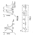
- the light signal S consists of a sequence of soliton-type pulses of different amplitude (denoted A 1 , A 2 , A 3 on the ordinate Y 10) distributed over time (in abscissa X 10).
- the nonlinear means 5 outputs the light wave multiplexed signal S f of which only half of the spectrum is shown diagrammatically in the diagram B of FIG. Figure 2A .
- the spectrum of the signal S f is represented solely by three spectral components S 1 , S 2 , S 3 whose amplitude is represented on the ordinate Y20 as a function of the wavelength on the abscissa X20.
- wavelength shift effect produced by the non-linear means 5 is all the more important that the peak power of the soliton pulses is high. In other words ⁇ 3 is all the greater as the amplitude A 3 is high.
- the Figure 2B illustrates, very schematically, the solitonic trapping phenomenon in a polarization-maintaining birefringent fiber 5, when a soliton pulse of amplitude A 1 is injected into the fiber at 45 ° from the proper axes of the fiber 5.
- this incident pulse is duplicated in two propagation modes along the two proper axes of the birefringent fiber 5.
- One of the modes is propagated along the fast axis while the other mode is spread along the slow axis. Since the polarization of the incident pulse is oriented at 45 ° to the proper axes of the fiber, this pulse is divided into two replicas of equal amplitude.
- Diagrams C and D of the Figure 2B represent respectively the temporal profile and the spectrum of the Soliton pulse of amplitude A 1 having undergone the solitonic trapping effect after having been injected into the fiber 5, this injection being carried out in such a way that the polarization of the initial pulse is oriented at 45 ° to the proper axes of the fiber 5.
- the dashed line profiles correspond to the mode propagated along the fast axis of the fiber 5 whereas the profiles drawn continuously correspond to the mode of the pulses propagating along the slow axis of the polarization maintaining birefringent fiber 5.
- the non-linear effect of solitonic trapping decomposes the spectrum of the soliton pulse of amplitude A 1 of central wavelength ⁇ 0 according to two spectral components denoted W 11 and W 12 , symmetrical with respect to to the central length ⁇ 0 of the incident pulse, as shown in the diagram D of the Figure 2B .
- the wavelength shift achieved by the non-linear solitonic trapping effect is denoted ⁇ 1 in absolute value.
- the spectral component W 11 is at the wavelength ⁇ 0 - ⁇ 1
- the spectral component W 12 is at the wavelength ⁇ 0 + ⁇ 1 .
- the two components W 11 , W 12 are all the more spectrally offset with respect to the length ⁇ 0 of the initial pulse, the amplitude A 1 of the initial pulse is high and therefore, the effect of Solitonic trapping is important.
- the figure 3 illustrates an exemplary embodiment of the converter 20 according to the invention.
- the converter 20 comprises a polarization-maintaining birefringent fiber 5 (non-linear means 5), a temporal compression fiber of the soliton pulses 22 (compression means 22), a polarizer 23 (polarization extraction means 23), a polarization controller 24.
- the two spectral components W 11 and W 12 of the Figure 2B generated by the polarization maintaining birefringent fiber 5 carry the same information. Therefore, at the output of this non-linear means 5, it is sufficient to recover only one of these spectral components (W 11 or W 12 ).
- the polarization controller 24 controls the polarization state of the pulses so as to ensure that the pulses are properly injected into the polarization-maintaining birefringent fiber 5 with a polarization oriented at 45 ° to the proper axes of the fiber 5. .
- the optical converter 20 may also comprise an optical amplifier 25.
- a compression means 22 consisting of a chalcogenide glass fiber element of nonlinear index n 2 equal to 2.10 -18 m 2 / W and effective area A eff equal to 50 ⁇ m 2 .
- the non-linear index n 2 of the chalcogenide glass fiber 22 is much higher than that of a standard glass fiber.
- this chalcogenide glass fiber 22 a level of chromatic dispersion D equal to 5 ps / nm / km.
- the dispersion length Z D is equal to 50.5 m.
- the average power of the corresponding pulse train is then equal to 4.4 dBm.
- the dispersion length L D and the nonlinear length L NL corresponding to the propagation of a pulse of 1 ps width and peak power P C in the chalcogenide glass nonlinear fiber 22 (compression means 22) are given by the following relationships:
- the D 2 ⁇ ⁇ c . ⁇ 2 ⁇ 2 ⁇ D
- the NL ⁇ AT eff 2 ⁇ ⁇ ⁇ not 2 ⁇ P VS
- the pulses can be considered as very close to solitons of order N if their peak power P C obeys the following relation:
- NOT 2 The D
- the compression factor is therefore about 25 (the width of the pulses after compression is equal to 40 fs) and the length of chalcogenide glass fiber 22 necessary to obtain this compression is equal to 6.65 m.
- This non-linear effect is manifested, for example, in a polarization-maintaining fiber 5, with soliton pulses whose polarization is oriented at 45 ° to the proper axes of this fiber 5.
- solitonic trapping effect can be achieved when both of the following conditions are met.
- the polarization maintaining fiber 5 (non-linear means 5) must be used in a nonlinear regime, that is to say that the incident pulses must have the physical characteristics (amplitude and width at half height ) solitons preferably of order 1 adapted to said polarization-maintaining fiber 5. Note that the solitonic trapping effect acts at best on solitons of order 1.
- Walk-off ⁇ ⁇ ⁇ ' . Z 0 ⁇ ⁇ 0 ⁇ 'being the polarization mode dispersion of the polarization maintaining fiber 5.
- ⁇ ⁇ ⁇ ⁇ not ⁇ ⁇ 0 1763 ⁇ ⁇ 2 ⁇ D
- ⁇ n the index variation between the proper birefringence axes of the polarization-maintaining fiber.
- the optical transmission system comprises 40 client terminals (or subscribers) with a client terminal rate equal to 1 Gbit / s
- 40 ridge power values judiciously distributed up to at 76 W (18.4 dBm)
- the power limit is therefore given by the power of the fundamental soliton or of order 1.
- the transmission power of each client terminal is chosen such that the wavelength of the pulses transmitted by each client terminal is converted, by solitonic trapping effect on the uplink, into a single target length. It will be noted that the amplitude of the pulses emitted by each client terminal is previously adjusted during an initial step of configuring the optical network.
- the crosstalk (or "crosstalk" in English) between different WDM channels (or different wavelengths) generated will not be noticeable due to the compression of the spectrum that will be generated in the standard fiber connecting the central terminal 1 to customer terminals.
- a chromatic dispersion compensation module must be put in place upstream of the demultiplexer 7 so as to compensate for the chromatic dispersion accumulated on the path made between the central unit 1 and the client terminals.
- the width of the initial pulses ie 40 fs
- the bit rate received by the client terminal is only 1 Gbit / s (which corresponds to a bit time equal to 1 ns).
- Bringing the pulses back to their bit time with a half-full width less than half the bit time (ie 500 ps) is more than enough.
- the tolerance on the fiber length that compensates for Standard Single Mode Fiber (SSMF) fiber is about 1 km. So, if the central-subscriber distance is 20 km, compensate for 19 km only SSMF is enough to reduce the pulse in the bit time with a width small enough for the photodetector to solve it.
- SSMF Standard Single Mode Fiber
- the numerical example above thus shows the effectiveness of the solitonic trapping effect to spectrally demultiplex a 40 Gbit / s data stream.
- the invention reconciles advantages of the two types of PON network architecture.
- a single wavelength ⁇ 0 is sent, while a low loss optical demultiplexer 7 is implemented in the network 3 so that at each client terminal (or subscriber) 11 , 12 or 13 is associated a wavelength ⁇ 1 , ⁇ 2 or ⁇ 3 which is very specific and on which are carried the data D 1 , D 2 or D 3 which are intended for it.
- the transformation based on the solitonic trapping effect according to the invention makes it possible to limit to a fiber length of a few meters in the case of a conventional PON type architecture comprising 40 subscribers. Indeed, according to the numerical example presented above, about 8 m of fiber in total is sufficient (in which are included the 6.65 m necessary for pulse compression). This has the advantage of producing fully passive converters with reduced space, easy to manufacture and low cost.
- the figures 4 and 5 show two embodiments of the central terminal 101, 100 according to the invention, in a bidirectional optical transmission system, comprising by way of example two client terminals 11 and 12.
- the central terminal 100, 101 is itself bi-directional (or "full-duplex" in English) in the sense that it can simultaneously handle downstream and upstream data flows.
- the optical transmission central terminal 100, 101 comprises a transmitter 30 intended to send on the downlink downward data D 1 , D 2 to a plurality client terminals 11, 12 during a downlink transmission phase.
- the central terminal 100, 101 furthermore comprises at least one receiver for receiving upstream data D ' 1 , D' 2 transmitted by the plurality of client terminals 11, 12 on the upstream link.
- the "downlink” is the communication link of the system according to which the downstream data D 1 , D 2 are transmitted from the central terminal 100, 101 to the plurality of client terminals 11, 12, during a downlink transmission phase.
- the "up link” is the communication link of the system according to which the upstream data D ' 1 , D' 2 are transmitted from the plurality of client terminals 11, 12 to the central terminal 100, 101, when a phase of rising transmission.
- the central terminal 100, 101 transmits to a plurality of client terminals 11, 12 the downstream data D 1 , D 2 carried by a light signal S, of single wavelength ⁇ 0 , multiplexed in amplitude and in time.
- the light signal S consists of a plurality of soliton pulses having a plurality of amplitudes.
- the signal S consists of a first series of pulses of amplitude A 1 (data D 1 ) and a second series of pulses of amplitude A 2 (data D 2 ).
- the optical converter 20 converts the single wavelength ⁇ 0 of the descending light signal S into two distinct wavelengths ⁇ 1 and ⁇ 2 as a function of the amplitudes A 1 and A 2 in order to forming a downlink wavelength multiplexed light signal S f carrying the falling data D 1 and D 2 , according to the respective wavelengths ⁇ 1 and ⁇ 2 .
- the wavelength multiplexed down-light signal S f is routed to the plurality of terminals clients 11, 12.
- routing means constituted by a WDM optical circulator 31 is placed in flux cutoff between the optical converter 20 and the optical network 3.
- the downward light signal S f multiplexed wavelengths is spectrally demultiplexed, so that each client terminal 11, 12 can receive the data intended for it (D1, D 2 respectively) according to a specific wavelength ( ⁇ 1 , ⁇ 2 respectively).
- optical demultiplexing means consisting of a WDM optical demultiplexer 7 are arranged in the optical network 3, between the WDM circulator 31 and the plurality of client terminals 11, 12.
- the optical transmission client terminals 11 and 12 each comprise a reception module or receiver respectively designated 16 and 18 for receiving the data carried by the spectral components S 1 , S 2 of the downward light signal S f .
- the downlink data D 1 (respectively D 2 ) carried by the spectral component S 1 (respectively S 2 ) at the wavelength ⁇ 1 (respectively ⁇ 2 ) are conveyed to the client terminal 11 (respectively 12) by a link optical and demodulated by the receiver 16 (respectively 18) of the client terminal 11 (respectively 12).
- S ' 1 (respectively S' 2 ) light signal emitted by the transmitter 16 (respectively 18) of the client terminal 11 (respectively 12) carrying the rising data D ' 1 (respectively D' 2 ) at the wavelength ⁇ ' 1 (respectively ⁇ ' 1 ) for the central terminal 100 or 101.
- each client terminal 11, 12 transmits the rising data D ' 1 , D' 2 to the central terminal 100, 101.
- the light signal amounts S ' 1 (respectively S' 2 ) is emitted at a specific amplitude A ' 1 (respectively A' 2 ) and with a predetermined time offset t ' 1 (respectively t' 2 ).
- the rising light signals S ' 1 and S' 2 are multiplexed in wavelengths by a multiplexer WDM 7 (multiplexing means), so as to form a rising light signal S ' f multiplexed in wavelengths.
- this multiplexer WDM 7 and the demultiplexer WDM 7 used for the downlink are constituted by a single component playing both the role of multiplexer and demultiplexer.
- the wavelength multiplexed optical signal S ' f is routed by the optical circulator 31 to at least one receiver intended to obtain the rising data D' 1 and D ' 2 emitted respectively by the customer terminals 11 and 12.
- the figure 4 illustrates a first embodiment of a bidirectional optical transmission system comprising a rising link and a downlink implementing the upstream and downstream transmission phases described above and in which the central terminal 100 comprises a reception demultiplexer 33 (second demultiplexing means), two data receivers 37 and 35 connected to the receiving demultiplexer 33, and the circulator 31 which is arranged between the converter 20 and the reception demultiplexer 33.
- the central terminal 100 comprises a reception demultiplexer 33 ( second demultiplexing means), two data receivers 37 and 35 connected to the receiving demultiplexer 33, and the circulator 31 which is arranged between the converter 20 and the reception demultiplexer 33.
- the wavelength multiplexed optical signal S ' f is spectrally demultiplexed by the reception demultiplexer 33, so as to distribute the spectral components S'1, S' 2 respectively to a first 35 and a second 37 data receiver.
- the rising data D'1 and D'2 respectively carried by the rising light signals S'1 and S'2 are respectively received by the first 35 and the second 37 data receiver according to the lengths of the data. respective waves.
- the data D ' 2 and D' 1 are recovered at the central terminal 100, after a wavelength demultiplexing of the signals S ' 1 and S' 2 produced by the reception demultiplexer 33.
- the conversion of the double amplitude and time-division multiplexed light signal S into a wavelength-multiplexed light signal S f for example from FIG. figure 4 relates to the light signals S 1 , S 2 on the downlink.
- the wavelength multiplexed upstream light signal S ' f can be transformed into an optical time division multiplexing (OTDM) signal. using an additional optical converter 21 based on the solitonic trapping effect, as illustrated in FIG. figure 5 in a second embodiment.
- OTDM optical time division multiplexing
- the wavelength multiplexed optical signal S ' f is injected into the second optical converter 21, which converts it during a transformation step by a non-linear solitonic trapping effect. in a single wavelength multiplexed ⁇ ' 0 rising signal carrying the rising data D' 1 , D ' 2.
- the optical nonlinear means of the second converter 21 is constituted by a polarization-maintaining birefringent fiber 5.
- the step of transforming the upstream transmission phase is performed by injecting the rising light signal S ' f multiplexed in wavelengths at 45 ° to the proper axes of a polarization-maintaining birefringent fiber 5.
- This second converter 21 has the effect of resetting the two channels carried by the wavelengths ⁇ ' 1 and ⁇ ' 2 on a single rising wavelength ⁇ ' 0 , whose value is taken, for example, slightly greater than that of the wavelength ⁇ 0 used in the downward direction in order to avoid interference between the uplink and the downlink.
- the single wavelength rising signal ⁇ ' 0 delivered at the output of the second optical converter 21 is demodulated by a single receiver 39 so as to recover the rising data D' 1 , D ' 2 on two separate channels.
- the advantage of this second embodiment is to have only one receiver 39 at the central terminal 101, provided that to fine-tune the transmission of the upstream signals S ' 1 , S' 2 so that these signals are correctly interposed in the time domain.
- each signal S ' 1 , S' 2 must be transmitted with a time shift t ' 1 and t' 2 such that after transformation by solitonic trapping effect, the signal obtained at the output of the second converter optical 21 is a signal multiplexed in time (OTDM signal).
Claims (15)
- Verfahren zur optischen Übertragung zwischen einem zentralen Endgerät (1) und mehreren Client-Endgeräten (11-13) über ein optisches Netz (3), das eine Phase der Downstream-Übertragung enthält, die dazu bestimmt ist, Downstream-Daten (D1-D3) zu übertragen, wobei das Verfahren dadurch gekennzeichnet ist, dass es die folgenden Schritte enthält:- Senden, durch das zentrale Endgerät (1), eines Downstream-Lichtsignals (S) mit einer einzigen Wellenlänge (λ0), das doppelt amplituden- und zeitmultiplexiert ist und die Downstream-Daten (D1-D3) trägt, die dazu bestimmt sind, von den mehreren Client-Endgeräten (11-13) empfangen zu werden, wobei das Downstream-Lichtsignal (S) mit einer einzigen Wellenlänge (λ0) aus Impulsen vom Typ Soliton besteht, die mehrere Amplituden (A1-A3) aufweisen;- Umwandlung, durch einen nichtlinearen Effekt des Solitonen-Einfangs, der einzigen Wellenlänge (λ0) des Downstream-Lichtsignals (S) in mehrere Wellenlängen (λ1-λ3) in Abhängigkeit von den mehreren Amplituden (A1-A3), um ein wellenlängenmultiplexiertes Downstream-Lichtsignal (Sf) zu formen;- Routen des wellenlängenmultiplexierten Downstream-Lichtsignals (Sf) zu den mehreren Client-Endgeräten (11-13); und- Wellenlängendemultiplexieren des wellenlängenmultiplexierten Downstream-Lichtsignals (Sf), so dass jedes Client-Endgerät (11-13) die für es bestimmten Daten (D1-D3) gemäß einer spezifischen Wellenlänge (λ1-λ3) empfängt.
- Verfahren zur optischen Übertragung zwischen einem zentralen Endgerät (100; 101) und mehreren Client-Endgeräten (11, 12) über ein optisches Netz (3), das eine Phase der Downstream-Übertragung, die dazu bestimmt ist, Downstream-Daten (D1, D2) zu übertragen, und eine Phase der Upstream-Übertragung enthält, die dazu bestimmt ist, Upstream-Daten (D'1, D'2) zu übertragen, wobei das Verfahren dadurch gekennzeichnet ist, dass die Phase der Downstream-Übertragung die folgenden Schritte enthält:- Senden, durch das zentrale Endgerät (100; 101), eines Downstream-Lichtsignals (S) mit einer einzigen Wellenlänge (λ0), das doppelt amplituden- und zeitmultiplexiert ist und die Downstream-Daten (D1, D2) trägt, die dazu bestimmt sind, von den mehreren Client-Endgeräten (11, 12) empfangen zu werden, wobei das Downstream-Lichtsignal (S) mit einer einzigen Wellenlänge (λ0) aus Impulsen vom Typ Soliton besteht, die mehrere Amplituden (A1, A2) aufweisen;- Umwandlung durch das zentrale Endgerät (100; 101), durch einen nichtlinearen Effekt des Solitonen-Einfangs, der einzigen Wellenlänge (λ0) des Downstream-Lichtsignals (S) in mehrere Wellenlängen (λ1, λ2) in Abhängigkeit von den mehreren Amplituden (A1, A2), um ein wellenlängenmultiplexiertes Downstream-Lichtsignal (Sf) zu formen;- Routen des wellenlängenmultiplexierten Downstream-Lichtsignals (Sf) zu den mehreren Client-Endgeräten (11, 12); und- Wellenlängendemultiplexieren des wellenlängenmultiplexierten Downstream-Lichtsignals (Sf), so dass jedes Client-Endgerät (11, 12) die für es bestimmten Daten (D1, D2) gemäß einer spezifischen Wellenlänge (λ1, λ2) empfängt.
- Verfahren zur optischen Übertragung nach Anspruch 2, bei dem die Phase der Upstream-Übertragung die folgenden Schritte enthält:- Senden von mehreren Upstream-Lichtsignalen (S'1, S'2) zum zentralen Endgerät (100; 101), wobei jedes Upstream-Lichtsignal jeweils die Upstream-Daten (D'1, D'2) auf einer unterschiedlichen Wellenlänge (λ'1, λ'2) trägt und jeweils von einem Client-Endgerät der mehreren Client-Endgeräte (11, 12) gemäß einer spezifischen Amplitude (A'1, A'2) und mit einer vorbestimmten Zeitverschiebung (t'1, t'2) gesendet wird;- Wellenlängenmultiplexieren der mehreren Upstream-Lichtsignale (S'1, S'2), um ein wellenlängenmultiplexiertes Upstream-Lichtsignal (S'f) zu formen; und- Routen des wellenlängenmultiplexierten Upstream-Lichtsignals (S'f) zu mindestens einem Empfänger, der dazu bestimmt ist, die von jedem Client-Endgerät der mehreren Client-Endgeräte (11, 12) gesendeten Daten (D'1, D'2) zu erhalten.
- Verfahren zur optischen Übertragung nach Anspruch 3, dadurch gekennzeichnet, dass die Phase der Upstream-Übertragung außerdem enthält:- einen Schritt des Wellenlängendemultiplexierens, in dem das wellenlängenmultiplexierte Upstream-Lichtsignal (S'f) spektral in mehrere Spektralkomponenten demultiplexiert wird; und- einen Schritt des Empfangs der Upstream-Daten durch mehrere Empfänger, in dem jede der Spektralkomponenten, die die von einem Client-Endgerät auf einer jeweiligen Wellenlänge gesendeten Upstream-Daten tragen, von einem Empfänger der mehreren Empfänger empfangen wird.
- Verfahren zur optischen Übertragung nach Anspruch 3, dadurch gekennzeichnet, dass die Phase der Upstream-Übertragung außerdem enthält:- einen Schritt der Umwandlung, in dem das wellenlängenmultiplexierte Upstream-Lichtsignal (S'f) durch einen nichtlinearen Effekt des Solitonen-Einfangs in ein zeitmultiplexiertes Upstream-Signal mit einer einzigen Wellenlänge (λ'0) umgewandelt wird, das die Upstream-Daten trägt; und- einen Schritt des Empfangs des Upstream-Signals mit einer einzigen Wellenlänge (λ'0) durch einen einzigen Empfänger (39).
- Verfahren zur optischen Übertragung nach einem der Ansprüche 1 bis 5, dadurch gekennzeichnet, dass es außerdem vor dem Umwandlungsschritt einen Schritt der zeitlichen Komprimierung der Impulse vom Typ Soliton enthält.
- System zur optischen Übertragung über ein optisches Netz (3), welches System ein zentrales Endgerät (1) und mehrere Client-Endgeräte (11-13) umfasst, wobei das zentrale Endgerät (1) dazu bestimmt ist, auf einem Downlink Downstream-Daten (D1-D3) an die mehreren Client-Endgeräte (11-13) zu senden, wobei das System dadurch gekennzeichnet ist, dass es auf dem Downlink enthält:- Einrichtungen (1) zum Senden eines Downstream-Lichtsignals (S) mit einer einzigen Wellenlänge (λ0) und das die Downstream-Daten (D1-D3) trägt, wobei das Downstream-Lichtsignal (S) doppelt zeit- und amplitudenmultiplexiert ist und aus Impulsen vom Typ Soliton besteht, die mehrere Amplituden (A1-A3) aufweisen;- eine nichtlineare Einrichtung (5), um durch einen Effekt des Solitonen-Einfangs die einzige Wellenlänge (λ0) des Downstream-Lichtsignals (S) in Abhängigkeit von den mehreren Amplituden (A1-A3) in mehrere Wellenlängen (λ1-λ3) umzuwandeln, um ein wellenlängenmultiplexiertes Downstream-Lichtsignal (Sf) zu formen;- eine Routing-Einrichtung, um das wellenlängenmultiplexierte Downstream-Lichtsignal (Sf) zu den mehreren Client-Endgeräten (11-13) zu routen; und- Demultiplexiereinrichtungen (7), um das Downstream-Lichtsignal (Sf) spektral zu demultiplexieren, damit jedes Client-Endgerät (11-13) die für es bestimmten Downstream-Daten (D1-D3) gemäß einer spezifischen Wellenlänge (λ1-λ3) empfängt.
- System zur optischen Übertragung über ein optisches Netz (3), welches System ein zentrales Endgerät (100; 101) und mehrere Client-Endgeräte (11, 12) umfasst, wobei das zentrale Endgerät (100; 101) dazu bestimmt ist, auf einem Downlink Downstream-Daten (D1, D2) an die mehreren Client-Endgeräte (11, 12) zu senden und auf einem Uplink von den mehreren Client-Endgeräten (11, 12) kommende Upstream-Daten (D'1, D'2) zu empfangen, wobei das System dadurch gekennzeichnet ist, dass das zentrale Endgerät (100; 101) enthält:- Einrichtungen (30) zum Senden eines Downstream-Lichtsignals (S) mit einer einzigen Wellenlänge (λ0) und das die Downstream-Daten (D1, D2) trägt, wobei das Downstream-Lichtsignal (S) doppelt zeit- und amplitudenmultiplexiert ist und aus Impulsen vom Typ Soliton besteht, die mehrere Amplituden (A1, A2) aufweisen;- eine nichtlineare Einrichtung (20), um durch einen Effekt des Solitonen-Einfangs die einzige Wellenlänge (λ0) des Downstream-Lichtsignals (S) in Abhängigkeit von den mehreren Amplituden (A1, A2) in mehrere Wellenlängen (λ1, λ2) umzuwandeln, um ein wellenlängenmultiplexiertes Downstream-Lichtsignal (Sf) zu formen;wobei das System außerdem enthält:- eine Routing-Einrichtung, um das wellenlängenmultiplexierte Downstream-Lichtsignal (Sf) zu den mehreren Client-Endgeräten (11, 12) zu routen; und- erste Demultiplexiereinrichtungen (7), um das Downstream-Lichtsignal (Sf) spektral zu demultiplexieren, damit jedes Client-Endgerät (11, 12) die für es bestimmten Downstream-Daten (D1, D2) gemäß einer spezifischen Wellenlänge (λ1, λ2) empfängt.
- System nach Anspruch 8, dadurch gekennzeichnet, dass das System außerdem auf dem Uplink enthält:- Einrichtungen (11; 12) zum Senden mehrerer Upstream-Lichtsignale (S'1, S'2) an das zentrale Endgerät (100; 101), wobei jedes Upstream-Lichtsignal jeweils die Upstream-Daten (D'1, D'2) mit einer unterschiedlichen Wellenlänge (λ'1, λ'2) trägt und jeweils von einem Client-Endgerät der mehreren Client-Endgeräte (11, 12) gemäß einer spezifischen Amplitude (A'1, A'2) und mit einer vorbestimmten Zeitverzögerung (t'1, t'2) gesendet wird;- Multiplexeinrichtungen (7), um die mehreren Upstream-Lichtsignale (S'1, S'2) zu wellenlängenmultiplexieren, um ein wellenlängenmultiplexiertes Upstream-Lichtsignal (S'f) zu formen;- Routing-Einrichtungen des wellenlängenmultiplexierten Upstream-Lichtsignals (S'f); und- mindestens einen Empfänger (35, 37; 39), der dazu bestimmt ist, die von jedem Client-Endgerät der mehreren Client-Endgeräte (11, 12) gesendeten Daten (D'1, D'2) zu erhalten.
- System nach Anspruch 8, dadurch gekennzeichnet, dass es außerdem auf dem Uplink enthält:- zweite Demultiplexiereinrichtungen (33), um das wellenlängenmultiplexierte Upstream-Lichtsignal (S'f) in mehrere Spektralkomponenten spektral zu demultiplexieren; und- mehrere Empfänger (35, 37) am Ausgang der zweiten Demultiplexiereinrichtungen, wobei jeder Empfänger geeignet ist, um von jeder Spektralkomponente getragene und von einem Client-Endgerät auf einer jeweiligen Wellenlänge gesendete Upstream-Daten zu empfangen.
- System nach Anspruch 8, dadurch gekennzeichnet, dass es außerdem auf dem Uplink enthält:- eine nichtlineare Einrichtung (5), die dazu bestimmt ist, durch einen Effekt des Solitonen-Einfangs das wellenlängenmultiplexierte Upstream-Lichtsignal (S'f) in ein zeitmultiplexiertes Upstream-Signal mit einer einzigen Wellenlänge (λ'0) umzuwandeln, das die Upstream-Daten trägt; und- Empfangseinrichtungen (39) des Upstream-Signals mit einer einzigen Wellenlänge (λ'0).
- System nach Anspruch 8, dadurch gekennzeichnet, dass es außerdem eine Einrichtung zur zeitlichen Komprimierung (22) enthält, die dazu bestimmt ist, die Impulse vom Typ Soliton zu komprimieren und sich vor der nichtlinearen Einrichtung (5) befindet.
- System nach Anspruch 8, dadurch gekennzeichnet, dass das optische Netz (3) ein passives optisches Zugangsnetz vom Typ PON ist.
- Zentrales Endgerät (100; 101) zur optischen Übertragung, gekennzeichnet durch:- einen Sender (30), der dazu bestimmt ist, Downstream-Daten (D1, D2) an mehrere Client-Endgeräte (11, 12) zu senden, wobei die Downstream-Daten von einem Downstream-Lichtsignal (S) mit einer einzigen Wellenlänge (λ0) getragen werden, das mehrere Impulse vom Typ Soliton enthält, wobei das Downstream-Lichtsignal (S) doppelt zeit- und amplitudenmultiplexiert ist und mehrere Amplituden (A1, A2) aufweist, und- mindestens einen Empfänger (35, 37; 39), der geeignet ist, um Upstream-Daten (D'1, D'2) zu empfangen, die von den mehreren Client-Endgeräten (11, 12) gesendet werden;wobei das zentrale Endgerät (100; 101) außerdem enthält:- eine Routing-Einrichtung (31), die es ermöglicht, die Downstream- und Upstream-Daten zu routen; und- einen ersten optischen Wandler (20), der zwischen dem Sender (30) und der Routing-Einrichtung (31) angeordnet ist, wobei der erste optische Wandler (20) eine nichtlineare Einrichtung (5) enthält, um durch einen Effekt des Solitonen-Einfangs die einzige Wellenlänge (λ0) des Downstream-Lichtsignals (S) in Abhängigkeit von den mehreren Amplituden (A1, A2) in mehrere Wellenlängen (λ1, λ2) umzuwandeln, um ein wellenlängenmultiplexiertes Downstream-Lichtsignal (Sf) zu formen.
- Endgerät (101) nach Anspruch 14, dadurch gekennzeichnet, dass es außerdem einen Datenempfänger (39) und einen zweiten optischen Wandler (21) enthält, der eine nichtlineare Einrichtung (5) enthält, wobei der zweite optische Wandler (21) zwischen der Routing-Einrichtung (31) und dem Datenempfänger (39) angeordnet ist.
Applications Claiming Priority (2)
| Application Number | Priority Date | Filing Date | Title |
|---|---|---|---|
| FR0513015 | 2005-12-21 | ||
| PCT/FR2006/051404 WO2007074297A1 (fr) | 2005-12-21 | 2006-12-20 | Transmission optique entre un terminal central et une pluralite de terminaux clients via un reseau optique |
Publications (2)
| Publication Number | Publication Date |
|---|---|
| EP1969748A1 EP1969748A1 (de) | 2008-09-17 |
| EP1969748B1 true EP1969748B1 (de) | 2010-10-20 |
Family
ID=36754594
Family Applications (1)
| Application Number | Title | Priority Date | Filing Date |
|---|---|---|---|
| EP06847194A Active EP1969748B1 (de) | 2005-12-21 | 2006-12-20 | Optische übertragung zwischen einem zentralen endgerät und mehreren client-endgeräten über ein optisches netzwerk |
Country Status (8)
| Country | Link |
|---|---|
| US (1) | US8611746B2 (de) |
| EP (1) | EP1969748B1 (de) |
| JP (1) | JP4870169B2 (de) |
| KR (1) | KR101376167B1 (de) |
| AT (1) | ATE485643T1 (de) |
| DE (1) | DE602006017744D1 (de) |
| ES (1) | ES2354376T3 (de) |
| WO (1) | WO2007074297A1 (de) |
Families Citing this family (18)
| Publication number | Priority date | Publication date | Assignee | Title |
|---|---|---|---|---|
| FR2884086A1 (fr) * | 2005-04-05 | 2006-10-06 | France Telecom | Transmission optique entre une premiere unite et une pluralite de secondes unites connectees entre elles au moyen d'un reseau d'acces optique passif |
| CN101114885B (zh) * | 2007-09-05 | 2011-07-27 | 华中科技大学 | 混合波分时分复用无源光网络系统、终端及信号传输方法 |
| CN113509407A (zh) | 2010-08-31 | 2021-10-19 | 资生堂美洲公司 | 皮肤组合物及其使用方法 |
| CA2848943C (en) | 2011-09-21 | 2021-04-13 | Living Proof, Inc. | Compositions and methods for treating conditions of compromised skin barrier function |
| EP2779497B1 (de) * | 2013-03-14 | 2017-05-03 | Danmarks Tekniske Universitet | Volloptisches Regenerationssystem für optische Wellenlängenmultiplex-Kommunikationssysteme |
| CN113662885B (zh) | 2015-11-09 | 2024-01-30 | 株式会社资生堂 | 用于在皮肤上应用的组合物和方法 |
| EP3679665A1 (de) * | 2017-09-05 | 2020-07-15 | Danmarks Tekniske Universitet | Optical line terminal und glasfaserzugangssystem mit erhöhter kapazität |
| US11451318B2 (en) | 2018-09-24 | 2022-09-20 | Danmarks Tekniske Universitet | Optical line terminal and optical fiber access system with increased flexibility |
| US10998982B2 (en) | 2019-04-18 | 2021-05-04 | Microsoft Technology Licensing, Llc | Transmitter for throughput increases for optical communications |
| US10938485B2 (en) | 2019-04-18 | 2021-03-02 | Microsoft Technology Licensing, Llc | Error control coding with dynamic ranges |
| US10873393B2 (en) | 2019-04-18 | 2020-12-22 | Microsoft Technology Licensing, Llc | Receiver training for throughput increases in optical communications |
| US10911155B2 (en) | 2019-04-18 | 2021-02-02 | Microsoft Technology Licensing, Llc | System for throughput increases for optical communications |
| US11018776B2 (en) | 2019-04-18 | 2021-05-25 | Microsoft Technology Licensing, Llc | Power-based decoding of data received over an optical communication path |
| US10897315B2 (en) * | 2019-04-18 | 2021-01-19 | Microsoft Technology Licensing, Llc | Power-based decoding of data received over an optical communication path |
| US10862591B1 (en) | 2019-04-18 | 2020-12-08 | Microsoft Technology Licensing, Llc | Unequal decision regions for throughput increases for optical communications |
| US10951342B2 (en) | 2019-04-18 | 2021-03-16 | Microsoft Technology Licensing, Llc | Throughput increases for optical communications |
| US10911152B2 (en) * | 2019-04-18 | 2021-02-02 | Microsoft Technology Licensing, Llc | Power-based decoding of data received over an optical communication path |
| ES2827373B2 (es) * | 2019-11-20 | 2021-09-21 | Telefonica Sa | Dispositivo óptico, método y sistema para la detección remota de terminales de red óptica |
Family Cites Families (13)
| Publication number | Priority date | Publication date | Assignee | Title |
|---|---|---|---|---|
| JPH0779198A (ja) * | 1993-09-08 | 1995-03-20 | Kokusai Denshin Denwa Co Ltd <Kdd> | 光通信システムおよび光送信装置 |
| JPH09214440A (ja) * | 1996-02-05 | 1997-08-15 | Kokusai Denshin Denwa Co Ltd <Kdd> | パルス情報の双方向伝送方式及び光送受信装置 |
| FR2813466B1 (fr) * | 2000-08-29 | 2002-12-13 | France Telecom | Regenerateur tout-optique pour signaux multiplexes en longueur d'onde |
| US7224906B2 (en) * | 2000-09-26 | 2007-05-29 | Celight, Inc. | Method and system for mitigating nonlinear transmission impairments in fiber-optic communications systems |
| GB0106553D0 (en) * | 2001-03-16 | 2001-05-02 | Univ Southampton | Timing jitter tolerant all-optical modulator and demultiplexing systems incorporating pulse-shaping fiber bragg gratings |
| JP2004527001A (ja) * | 2001-04-11 | 2004-09-02 | ユニバーシティ、オブ、サウサンプトン | 光パルス光源および光パルスを生成するための方法 |
| US7155127B2 (en) * | 2001-08-15 | 2006-12-26 | Nippon Telegraph And Telephone Corporation | Optical communication system, optical communication unit, and optical transceiving package |
| FR2838836B1 (fr) * | 2002-04-19 | 2004-08-20 | France Telecom | Dispositif optique et procede pour convertir des signaux wdm en un signal otdm, et reciproquement |
| US7725042B2 (en) | 2002-04-22 | 2010-05-25 | Marvin Ray Young | Automated optical transport system |
| JP4041007B2 (ja) | 2002-05-13 | 2008-01-30 | 日本電信電話株式会社 | 光多重通信方法、光多重通信システム、光信号多重化装置、および光多重信号分離装置 |
| US7272317B2 (en) * | 2002-05-13 | 2007-09-18 | Nippon Telegraph And Telephone Corporation | Optical multiplexing communication system using ultra high speed signal transmission |
| US20040141748A1 (en) * | 2003-01-22 | 2004-07-22 | Ralph Spickermann | Use of coarse WDM channels for upstream traffic in fiber-to-the-home systems |
| FR2884086A1 (fr) * | 2005-04-05 | 2006-10-06 | France Telecom | Transmission optique entre une premiere unite et une pluralite de secondes unites connectees entre elles au moyen d'un reseau d'acces optique passif |
-
2006
- 2006-12-20 ES ES06847194T patent/ES2354376T3/es active Active
- 2006-12-20 EP EP06847194A patent/EP1969748B1/de active Active
- 2006-12-20 AT AT06847194T patent/ATE485643T1/de not_active IP Right Cessation
- 2006-12-20 DE DE602006017744T patent/DE602006017744D1/de active Active
- 2006-12-20 JP JP2008546558A patent/JP4870169B2/ja active Active
- 2006-12-20 WO PCT/FR2006/051404 patent/WO2007074297A1/fr active Application Filing
- 2006-12-20 US US12/087,027 patent/US8611746B2/en active Active
- 2006-12-20 KR KR1020087017440A patent/KR101376167B1/ko active IP Right Grant
Also Published As
| Publication number | Publication date |
|---|---|
| ES2354376T3 (es) | 2011-03-14 |
| JP2009521158A (ja) | 2009-05-28 |
| WO2007074297A1 (fr) | 2007-07-05 |
| ATE485643T1 (de) | 2010-11-15 |
| EP1969748A1 (de) | 2008-09-17 |
| DE602006017744D1 (de) | 2010-12-02 |
| US20100221011A1 (en) | 2010-09-02 |
| KR20080087830A (ko) | 2008-10-01 |
| JP4870169B2 (ja) | 2012-02-08 |
| KR101376167B1 (ko) | 2014-03-19 |
| US8611746B2 (en) | 2013-12-17 |
Similar Documents
| Publication | Publication Date | Title |
|---|---|---|
| EP1969748B1 (de) | Optische übertragung zwischen einem zentralen endgerät und mehreren client-endgeräten über ein optisches netzwerk | |
| EP1788736B1 (de) | Verbesserte Datenübertragungsvorrichtung zur Kommunikationseinrichtungen in einem passiven optischen Netzwerk | |
| EP0897624B1 (de) | Verfahren und vorrichtung zur online wiedererzeugung eines durch wellenlängenmultiplexsolitons übertragenen signals und optisches nachrichtenübertragungssystem mit einer derartigen vorrichtung zur wiedererzeugung | |
| FR2715524A1 (fr) | Système de communication de type soliton optique ainsi qu'émetteur et récepteur optiques pour ce système. | |
| US8064768B2 (en) | Intra-channel equalizing optical interleaver | |
| CN105934899A (zh) | 光网络单元(onu)波长自调谐 | |
| JPH09214429A (ja) | 光アクセス方式 | |
| FR2724795A1 (fr) | Dispositif de reception de lumiere, appareil de transmission optique et procede de demultiplexage | |
| EP2775643A1 (de) | Passives optisches Netzwerk mit Unterteilungs-Multiplexing mit hochdichter Wellenlänge | |
| EP1657840B1 (de) | DWDM-Kommunikationsnetz mit periodischer Wellenlängen-Multiplexierung | |
| EP1867086B1 (de) | Optische übertragung zwischen einer ersten einheit und mehreren zweiten einheiten, die mittels eines passiven optischen zugangsnetzes verbunden sind | |
| EP1315320A2 (de) | Faseroptisches Übertragungssystem mit gemeinsamem Takt | |
| FR2829327A1 (fr) | Reseau en anneau realise a partir d'un bus optique double | |
| FR2736480A1 (fr) | Disposif de coloration de signaux optiques | |
| EP1228589B1 (de) | Faseroptisches übertragungssystem mit optischen rz-pulsen | |
| EP1398896A1 (de) | Frequenzkamm für ein Netzwerk mit optischer Frequenzmultiplexierung | |
| Chan et al. | Provision of independent services in WDM-passive optical networks using closely separated dual baseband channels | |
| Pal et al. | Analysis of 32-channel 40 Gbit/s DWDM in Point-to-Point topology | |
| EP2009827B1 (de) | Vorrichtung zum optischen Zeitdemultiplexen | |
| WO2016059330A1 (fr) | Dispositif, systeme et procede emetteur-recepteur optoelectronique wdm en cascade | |
| Al Zahr | Planification de réseaux WDM translucides avec qualité de transmission garantie | |
| EP0924883A1 (de) | Reduktion von kollisionsinduziertem Zeitjitter in einem Wellenlängenmultiplexsolitonübertragungssystem durch Veränderung der Wellenlängen | |
| FR2796784A1 (fr) | Recepteur optique et dispositif d'addition/de reduction optique | |
| Han | Flexible optical transport networks: benefits of the combination of time and spectral domains to adapt the granularity of optical resources to the needs of operators | |
| EP1142167A1 (de) | Faseroptische übertragungssysteme mit kompensation der chromatischen dispersion |
Legal Events
| Date | Code | Title | Description |
|---|---|---|---|
| PUAI | Public reference made under article 153(3) epc to a published international application that has entered the european phase |
Free format text: ORIGINAL CODE: 0009012 |
|
| 17P | Request for examination filed |
Effective date: 20080716 |
|
| AK | Designated contracting states |
Kind code of ref document: A1 Designated state(s): AT BE BG CH CY CZ DE DK EE ES FI FR GB GR HU IE IS IT LI LT LU LV MC NL PL PT RO SE SI SK TR |
|
| 17Q | First examination report despatched |
Effective date: 20090127 |
|
| GRAP | Despatch of communication of intention to grant a patent |
Free format text: ORIGINAL CODE: EPIDOSNIGR1 |
|
| DAX | Request for extension of the european patent (deleted) | ||
| GRAS | Grant fee paid |
Free format text: ORIGINAL CODE: EPIDOSNIGR3 |
|
| GRAA | (expected) grant |
Free format text: ORIGINAL CODE: 0009210 |
|
| AK | Designated contracting states |
Kind code of ref document: B1 Designated state(s): AT BE BG CH CY CZ DE DK EE ES FI FR GB GR HU IE IS IT LI LT LU LV MC NL PL PT RO SE SI SK TR |
|
| REG | Reference to a national code |
Ref country code: GB Ref legal event code: FG4D Free format text: NOT ENGLISH |
|
| REG | Reference to a national code |
Ref country code: CH Ref legal event code: EP |
|
| REG | Reference to a national code |
Ref country code: IE Ref legal event code: FG4D Free format text: LANGUAGE OF EP DOCUMENT: FRENCH |
|
| REF | Corresponds to: |
Ref document number: 602006017744 Country of ref document: DE Date of ref document: 20101202 Kind code of ref document: P |
|
| REG | Reference to a national code |
Ref country code: NL Ref legal event code: VDEP Effective date: 20101020 |
|
| REG | Reference to a national code |
Ref country code: ES Ref legal event code: FG2A Effective date: 20110302 |
|
| LTIE | Lt: invalidation of european patent or patent extension |
Effective date: 20101020 |
|
| PG25 | Lapsed in a contracting state [announced via postgrant information from national office to epo] |
Ref country code: LT Free format text: LAPSE BECAUSE OF FAILURE TO SUBMIT A TRANSLATION OF THE DESCRIPTION OR TO PAY THE FEE WITHIN THE PRESCRIBED TIME-LIMIT Effective date: 20101020 |
|
| REG | Reference to a national code |
Ref country code: IE Ref legal event code: FD4D |
|
| PG25 | Lapsed in a contracting state [announced via postgrant information from national office to epo] |
Ref country code: IS Free format text: LAPSE BECAUSE OF FAILURE TO SUBMIT A TRANSLATION OF THE DESCRIPTION OR TO PAY THE FEE WITHIN THE PRESCRIBED TIME-LIMIT Effective date: 20110220 Ref country code: BG Free format text: LAPSE BECAUSE OF FAILURE TO SUBMIT A TRANSLATION OF THE DESCRIPTION OR TO PAY THE FEE WITHIN THE PRESCRIBED TIME-LIMIT Effective date: 20110120 Ref country code: SI Free format text: LAPSE BECAUSE OF FAILURE TO SUBMIT A TRANSLATION OF THE DESCRIPTION OR TO PAY THE FEE WITHIN THE PRESCRIBED TIME-LIMIT Effective date: 20101020 Ref country code: SE Free format text: LAPSE BECAUSE OF FAILURE TO SUBMIT A TRANSLATION OF THE DESCRIPTION OR TO PAY THE FEE WITHIN THE PRESCRIBED TIME-LIMIT Effective date: 20101020 Ref country code: PT Free format text: LAPSE BECAUSE OF FAILURE TO SUBMIT A TRANSLATION OF THE DESCRIPTION OR TO PAY THE FEE WITHIN THE PRESCRIBED TIME-LIMIT Effective date: 20110221 Ref country code: NL Free format text: LAPSE BECAUSE OF FAILURE TO SUBMIT A TRANSLATION OF THE DESCRIPTION OR TO PAY THE FEE WITHIN THE PRESCRIBED TIME-LIMIT Effective date: 20101020 Ref country code: AT Free format text: LAPSE BECAUSE OF FAILURE TO SUBMIT A TRANSLATION OF THE DESCRIPTION OR TO PAY THE FEE WITHIN THE PRESCRIBED TIME-LIMIT Effective date: 20101020 Ref country code: LV Free format text: LAPSE BECAUSE OF FAILURE TO SUBMIT A TRANSLATION OF THE DESCRIPTION OR TO PAY THE FEE WITHIN THE PRESCRIBED TIME-LIMIT Effective date: 20101020 Ref country code: FI Free format text: LAPSE BECAUSE OF FAILURE TO SUBMIT A TRANSLATION OF THE DESCRIPTION OR TO PAY THE FEE WITHIN THE PRESCRIBED TIME-LIMIT Effective date: 20101020 |
|
| BERE | Be: lapsed |
Owner name: FRANCE TELECOM Effective date: 20101231 |
|
| PG25 | Lapsed in a contracting state [announced via postgrant information from national office to epo] |
Ref country code: GR Free format text: LAPSE BECAUSE OF FAILURE TO SUBMIT A TRANSLATION OF THE DESCRIPTION OR TO PAY THE FEE WITHIN THE PRESCRIBED TIME-LIMIT Effective date: 20110121 |
|
| PG25 | Lapsed in a contracting state [announced via postgrant information from national office to epo] |
Ref country code: MC Free format text: LAPSE BECAUSE OF NON-PAYMENT OF DUE FEES Effective date: 20101231 Ref country code: IE Free format text: LAPSE BECAUSE OF FAILURE TO SUBMIT A TRANSLATION OF THE DESCRIPTION OR TO PAY THE FEE WITHIN THE PRESCRIBED TIME-LIMIT Effective date: 20101020 Ref country code: CZ Free format text: LAPSE BECAUSE OF FAILURE TO SUBMIT A TRANSLATION OF THE DESCRIPTION OR TO PAY THE FEE WITHIN THE PRESCRIBED TIME-LIMIT Effective date: 20101020 Ref country code: EE Free format text: LAPSE BECAUSE OF FAILURE TO SUBMIT A TRANSLATION OF THE DESCRIPTION OR TO PAY THE FEE WITHIN THE PRESCRIBED TIME-LIMIT Effective date: 20101020 |
|
| REG | Reference to a national code |
Ref country code: CH Ref legal event code: PL |
|
| PLBE | No opposition filed within time limit |
Free format text: ORIGINAL CODE: 0009261 |
|
| STAA | Information on the status of an ep patent application or granted ep patent |
Free format text: STATUS: NO OPPOSITION FILED WITHIN TIME LIMIT |
|
| PG25 | Lapsed in a contracting state [announced via postgrant information from national office to epo] |
Ref country code: SK Free format text: LAPSE BECAUSE OF FAILURE TO SUBMIT A TRANSLATION OF THE DESCRIPTION OR TO PAY THE FEE WITHIN THE PRESCRIBED TIME-LIMIT Effective date: 20101020 Ref country code: PL Free format text: LAPSE BECAUSE OF FAILURE TO SUBMIT A TRANSLATION OF THE DESCRIPTION OR TO PAY THE FEE WITHIN THE PRESCRIBED TIME-LIMIT Effective date: 20101020 Ref country code: RO Free format text: LAPSE BECAUSE OF FAILURE TO SUBMIT A TRANSLATION OF THE DESCRIPTION OR TO PAY THE FEE WITHIN THE PRESCRIBED TIME-LIMIT Effective date: 20101020 Ref country code: DK Free format text: LAPSE BECAUSE OF FAILURE TO SUBMIT A TRANSLATION OF THE DESCRIPTION OR TO PAY THE FEE WITHIN THE PRESCRIBED TIME-LIMIT Effective date: 20101020 |
|
| 26N | No opposition filed |
Effective date: 20110721 |
|
| PG25 | Lapsed in a contracting state [announced via postgrant information from national office to epo] |
Ref country code: BE Free format text: LAPSE BECAUSE OF NON-PAYMENT OF DUE FEES Effective date: 20101231 |
|
| PG25 | Lapsed in a contracting state [announced via postgrant information from national office to epo] |
Ref country code: LI Free format text: LAPSE BECAUSE OF NON-PAYMENT OF DUE FEES Effective date: 20101231 Ref country code: CH Free format text: LAPSE BECAUSE OF NON-PAYMENT OF DUE FEES Effective date: 20101231 |
|
| REG | Reference to a national code |
Ref country code: DE Ref legal event code: R097 Ref document number: 602006017744 Country of ref document: DE Effective date: 20110721 |
|
| PG25 | Lapsed in a contracting state [announced via postgrant information from national office to epo] |
Ref country code: CY Free format text: LAPSE BECAUSE OF FAILURE TO SUBMIT A TRANSLATION OF THE DESCRIPTION OR TO PAY THE FEE WITHIN THE PRESCRIBED TIME-LIMIT Effective date: 20101020 |
|
| PG25 | Lapsed in a contracting state [announced via postgrant information from national office to epo] |
Ref country code: LU Free format text: LAPSE BECAUSE OF NON-PAYMENT OF DUE FEES Effective date: 20101220 Ref country code: HU Free format text: LAPSE BECAUSE OF FAILURE TO SUBMIT A TRANSLATION OF THE DESCRIPTION OR TO PAY THE FEE WITHIN THE PRESCRIBED TIME-LIMIT Effective date: 20110421 |
|
| PG25 | Lapsed in a contracting state [announced via postgrant information from national office to epo] |
Ref country code: TR Free format text: LAPSE BECAUSE OF FAILURE TO SUBMIT A TRANSLATION OF THE DESCRIPTION OR TO PAY THE FEE WITHIN THE PRESCRIBED TIME-LIMIT Effective date: 20101020 |
|
| REG | Reference to a national code |
Ref country code: FR Ref legal event code: PLFP Year of fee payment: 10 |
|
| REG | Reference to a national code |
Ref country code: FR Ref legal event code: PLFP Year of fee payment: 11 |
|
| REG | Reference to a national code |
Ref country code: FR Ref legal event code: PLFP Year of fee payment: 12 |
|
| PGFP | Annual fee paid to national office [announced via postgrant information from national office to epo] |
Ref country code: IT Payment date: 20221122 Year of fee payment: 17 |
|
| PGFP | Annual fee paid to national office [announced via postgrant information from national office to epo] |
Ref country code: ES Payment date: 20230102 Year of fee payment: 17 |
|
| PGFP | Annual fee paid to national office [announced via postgrant information from national office to epo] |
Ref country code: GB Payment date: 20231121 Year of fee payment: 18 |
|
| PGFP | Annual fee paid to national office [announced via postgrant information from national office to epo] |
Ref country code: FR Payment date: 20231122 Year of fee payment: 18 Ref country code: DE Payment date: 20231121 Year of fee payment: 18 |
|
| PGFP | Annual fee paid to national office [announced via postgrant information from national office to epo] |
Ref country code: ES Payment date: 20240102 Year of fee payment: 18 |