EP1969433B1 - Transport system for monitoring industrial processes - Google Patents
Transport system for monitoring industrial processes Download PDFInfo
- Publication number
- EP1969433B1 EP1969433B1 EP06845768A EP06845768A EP1969433B1 EP 1969433 B1 EP1969433 B1 EP 1969433B1 EP 06845768 A EP06845768 A EP 06845768A EP 06845768 A EP06845768 A EP 06845768A EP 1969433 B1 EP1969433 B1 EP 1969433B1
- Authority
- EP
- European Patent Office
- Prior art keywords
- door
- camera
- rail
- pneumatic system
- move
- Prior art date
- Legal status (The legal status is an assumption and is not a legal conclusion. Google has not performed a legal analysis and makes no representation as to the accuracy of the status listed.)
- Ceased
Links
Images




Classifications
-
- G—PHYSICS
- G05—CONTROLLING; REGULATING
- G05B—CONTROL OR REGULATING SYSTEMS IN GENERAL; FUNCTIONAL ELEMENTS OF SUCH SYSTEMS; MONITORING OR TESTING ARRANGEMENTS FOR SUCH SYSTEMS OR ELEMENTS
- G05B19/00—Program-control systems
- G05B19/02—Program-control systems electric
- G05B19/04—Program control other than numerical control, i.e. in sequence controllers or logic controllers
- G05B19/042—Program control other than numerical control, i.e. in sequence controllers or logic controllers using digital processors
-
- G—PHYSICS
- G05—CONTROLLING; REGULATING
- G05B—CONTROL OR REGULATING SYSTEMS IN GENERAL; FUNCTIONAL ELEMENTS OF SUCH SYSTEMS; MONITORING OR TESTING ARRANGEMENTS FOR SUCH SYSTEMS OR ELEMENTS
- G05B2219/00—Program-control systems
- G05B2219/20—Pc systems
- G05B2219/24—Pc safety
- G05B2219/24028—Explosion free control, intrinsically safe
-
- G—PHYSICS
- G05—CONTROLLING; REGULATING
- G05B—CONTROL OR REGULATING SYSTEMS IN GENERAL; FUNCTIONAL ELEMENTS OF SUCH SYSTEMS; MONITORING OR TESTING ARRANGEMENTS FOR SUCH SYSTEMS OR ELEMENTS
- G05B2223/00—Indexing scheme associated with group G05B23/00
- G05B2223/06—Remote monitoring
Definitions
- the invention relates to systems and methods for introducing and withdrawing equipment into an environment, and in particular, introducing and withdrawing a camera into a high temperature environment.
- Harsh and extreme environments include high temperature environments such as the inside of a furnace, caustic chemical environments, and high pressure environments. The extremes of these environments however do not lessen the need for the monitoring of the industrial process. Consequently, industries would benefit from a system that could monitor industrial processes under extreme conditions.
- the invention consists in an apparatus comprising:
- the invention consist in a method comprising:
- Figures 1 and 2 illustrate an embodiment of a transport system that moves a visible and/or an infrared (IR) camera enclosed in an industrial housing along a rail. While the embodiment of Figures 1 and 2 show a transport system of the invention in connection with an IR camera; those of skill in the art will readily realize that the invention is not limited to an IR camera, but that embodiments of the transport system of Figures 1 and 2 could also transport other pieces of equipment as well. Additionally, while the embodiment of Figure 1 is discussed in connection with an industrial furnace, those of skill in the art will readily realize that the transport system of Figures 1 and 2 can be used in connection with other pieces of industrial equipment also.
- IR infrared
- the support and transport structure 100 of Figure 1 has a frame 105. Attached to the frame 105 is a first motion transport system.
- the first motion transport system is a pneumatic transport system that consists of a rail 110 and a trolley structure 115.
- the rail 110 is one that is manufactured by Tol-o-matic® of Hamel, Minnesota (www.tolomatic.com ).
- the frame 105 is attached to the outside of the wall of an industrial housing 140, and the pneumatic transport system is attached to the frame 105.
- the wall of the industrial housing 140 is an outside wall of a furnace.
- Positioned on top of the trolley structure 115 is an enclosure 120.
- the enclosure 120 contains a stepper motor 126 and a shaft 127.
- the stepper motor and shaft have wheels 128, 129 attached thereto respectively, and wheels 128, 129 are coupled via a belt, a chain, a gearing system or other means 130. ( See Figure 2 ).
- a control box 137 that houses a control processor and electrical and pneumatic controls. Also attached to the control box 137 is a reservoir 138 for the storage of pneumatic air.
- a second industrial housing 135 is connected to the end of shaft 127 opposite that of the wheel 129. In an embodiment, the industrial housing 135 encloses a camera, such as an IR camera.
- a second motion transport system that, like the first motion transport system, may be a pneumatic transport system. In the embodiment of Figure 1 , such a pneumatic transport system has a rail 150, a second trolley structure 156, and a door 154.
- the second trolley structure is attached to the door 154 with attachments 157 and tension springs 153 that attach the door 154 to the pneumatic transport system via a door trolley structure 156.
- the door trolley 156 in Figures 1 and 2 is depicted in generic form to indicate that several connecting mechanisms known in the art could be used to connect the door 154 to the trolley structure 156.
- the attachment 157 includes a triangular bracket 157a and a roller 158b to connect the bracket 157a to the trolley structure 156.
- the door covers an opening 160 in the industrial housing wall 140 ( Figure 2 ).
- the transport system 100 supports and transports the industrial housing 135 into and out of an industrial environment.
- the industrial environment is a furnace
- the industrial housing 135 encloses an IR camera.
- An exploded view of an embodiment of an industrial housing 135 and an IR camera is illustrated in Figure 3 .
- the housing 135 has a bottom plate 171, and encloses a camera 170.
- An opening 172 receives the camera lens (not shown in Figure 3 ) that is attached to the camera 170.
- the camera lens is enclosed and protected by a window 173 and lens housing 174 that is attached to the industrial housing.
- a coupling unit 175 attaches onto the housing wall, and serves to connect the housing 135 to the shaft 127.
- the industrial housing 135 is manufactured out of hardened stainless steel, and the window 173 is made out of sapphire.
- the lens attached to the camera may be a wide angle lens, a narrow angle lens, and/or a telescoping lens.
- the door 154 has been moved in the direction of arrow A.
- the movement of the door along arrow A occurs by activating the second pneumatic transport system, which moves door trolley 156 and the door 154 along rail 150, thereby exposing opening 160 in the industrial wall 140.
- attachments 157 A&B and tension springs 153 A&B secure the door 154 to the door trolley 156.
- the attachment 157 between door trolley 156 and the door 154 has compression springs 157C to ensure a tight seal between the door 154 and the wall 140 when the door trolley 156 is in the lowered position.
- Tension springs 153 A&B between door 154 and door trolley 156 is to ensure the door is held against the door trolley and away from the wall 140 when the door trolley is in the upper position.
- the compression spring force of attachments 157 A&B releases and tension springs 153 A&B pull door 154 toward door trolley 156 and away from the wall 140. This ensures that there is no interference between the door 154 and the wall 140 or other structure.
- both the door trolley 156 and door 154 move in the direction of arrow A.
- attachment 157A pushes the door 154 away from the door trolley 156 toward wall 140.
- the tension spring 153A first pulls the door 154 back away from the industrial wall 140 and then door trolley 156 and door 154 move together in the direction of arrow A.
- an adapter can be welded or otherwise coupled onto the wall of the industrial housing. The surface of the adapter that contacts the door 154 can then be machined to accurately mate with the door.
- Figure 2 further shows that enclosure 120, shaft 127, and housing 135 have been moved along rail 110 via the activation of the first pneumatic transport system.
- the housing 135 itself has been moved through opening 160 into the industrial housing 140.
- Figure 2 further illustrates that the industrial housing 135 has been rotated from a home position as illustrated in Figure 1 (as determined by the direction that the window 173 and lens housing 174 is pointed), to a deployed position as illustrated in Figure 2 .
- the industrial housing is attached to the shaft 127 by a mechanism that allows the industrial housing 135 to tilt when it is in the industrial housing 140.
- the transport structure 100 is connected to a processor housed in control box 137 that controls the functions of the transport system 100.
- a flowchart outlining an embodiment of the control process is illustrated in Figure 4 .
- the control process 400 at block 405 (a process control computer) transmits a signal to the camera 170 to determine the temperature of the camera. If the temperature of the camera is too high, for example because of a recent incursion into a furnace, the process control will not move the camera into the furnace.
- a timed loop is programmed into the processor logic to poll the temperature again, and see if the temperature is low enough to be inserted into the furnace.
- the insertion of the camera is on a timed and scheduled basis, and the system then waits for the next scheduled time to insert the camera into the furnace.
- an operator provides a command to the processor to move the camera into the furnace, and if insertion does not occur because the temperature of the camera is too high, the operator can wait before reissuing the command.
- image and rotation angle commands are transmitted from the camera to a programmable logic controller (PLC) housed in control box 137 (block 412).
- PLC programmable logic controller
- the image command readies the IR camera 170 for capturing images, and the rotation command is sent to the PLC which communicates with the stepper motor controller, housed in control box 137, which rotates the camera so that the window 173 and lens housing 174 will be pointed in the desired direction at 427.
- the PLC checks to see if the industrial housing 135, the enclosure 120, and the control box 137 have been successfully purged.
- a purge system 139 housed in control box 137, establishes a positive pressure in the enclosure 120, the control box 137, and the housing 135. This positive pressure keeps contaminants from leaking into these structures. If the Purge is OK, the PLC then checks in block 420 whether the camera 135 is out and the door 154 is closed. If the camera is out and the door 154 to the housing 140 is closed, the PLC checks in block 425 to see if the camera window 173 and lens housing 174 are located in the home position. If the camera is home, signals are then sent to the stepper motor at 427 so that the camera is rotated the desired number of degrees to the desired angle ( i . e . the deployed position).
- a variable representing the health or status of the PLC is set to zero and sent to the camera in block 430, and the camera communicates a PLC health error indication to the process computer.
- the processor sends a signal to energize a pneumatic valve which opens the door 154 that seals the housing 140.
- the processor checks to see if the door successfully opened. If the door did not open successfully, the PLC health status is set to zero at 430, and the PLC sends the information to the camera. If the door successfully opened, the first pneumatic transport system is energized at 447, and the housing 135 and camera 170 are moved through the housing wall 140. The processor then determines if the camera was moved into the housing successfully at 450. If it was not, the PLC status is once again set to zero. If the processor determines that the camera was moved into the furnace successfully, images are captured by the camera at 460.
- the camera then communicates with the process computer in block 405 and transfers the images. These images may be transmitted via wired or unwired means. Then, after a short time in the furnace at 465 (three seconds in one embodiment), the PLC sends a signal to the first pneumatic transport system at 470 to energize the valve again so that the housing and camera are removed from the furnace. The PLC checks to see if the camera was successfully removed from the furnace at 475. If it was, not, the PLC status is set to zero. If the camera was successfully removed from the furnace, the close door valve of the second pneumatic transport system is reenergized at 480, and the door 154 is closed. The PLC checks to see if the door was successfully closed (485), and if it was not, PLC status is set to zero.
- the processor status is set to zero and the system goes into a failsafe state. If instrument air is lost in the failsafe state, the pneumatic air in the reservoir 138 is used by the system to remove the camera from the furnace (if the camera is in the furnace wen the problem occurs), and to shut the door 154 (if once again the door is open when the problem occurs).
- This failsafe operation prevents the situation where the furnace door remains open because of a failure of some part of the system.
- an alternative power supply such as a battery or gas-powered generator, could be used to put the system into the failsafe mode.
Landscapes
- Physics & Mathematics (AREA)
- General Physics & Mathematics (AREA)
- Engineering & Computer Science (AREA)
- Automation & Control Theory (AREA)
- Waste-Gas Treatment And Other Accessory Devices For Furnaces (AREA)
- Testing Or Calibration Of Command Recording Devices (AREA)
- Studio Devices (AREA)
- Power-Operated Mechanisms For Wings (AREA)
Abstract
Description
- The invention relates to systems and methods for introducing and withdrawing equipment into an environment, and in particular, introducing and withdrawing a camera into a high temperature environment.
- Industrial processes should be closely monitored so that all process parameters can be verified as being within specification. This monitoring can take on many forms, and usually falls into two broad categories. Physical inspection and monitoring by humans, or physical inspection and monitoring by computer systems. In both cases, inspections and monitoring are aided by many other pieces of equipment such as all types of sensors (temperature, air quality, viscosity, density, visual appearance, etc.). One example of a monitoring system is disclosed in
US 2005/0018074 . - In some situations however, the environment that must be monitored is too harsh and extreme for either a human or a standard device or piece of equipment. Harsh and extreme environments include high temperature environments such as the inside of a furnace, caustic chemical environments, and high pressure environments. The extremes of these environments however do not lessen the need for the monitoring of the industrial process. Consequently, industries would benefit from a system that could monitor industrial processes under extreme conditions.
- In a first aspect, the invention consists in an apparatus comprising:
- a frame;
- a first pneumatic system attached to said frame; a second pneumatic system attached to said frame;
- an industrial housing connected to said first pneumatic system;
- a motor, said motor connected to said first pneumatic system and said industrial housing;
- a shaft, said shaft connecting said motor to said industrial housing;
- a programmable logic controller coupled to said first pneumatic system and said second pneumatic system, said programmable logic controller housed in a control box;
- an enclosure to house said motor;
- a door connected to said second pneumatic system;
- a purge system to establish a positive pressure within said control box, said enclosure that houses said motor, and said industrial housing; and
- a piece of industrial equipment, said frame attached to said piece of industrial equipment.
- In a second aspect, the invention consist in a method comprising:
- determining a temperature of a camera;
- rotating said camera to a deployed position;
- applying a positive internal pressure to said camera;
- opening a door covering an opening in a furnace;
- moving said camera, using a transport system, into said furnace;
- capturing images with said camera inside of said furnace;
- removing said camera from said furnace;
- transmitting said images to a processor;
- closing said door after said camera has been removed;
- verifying that said door has closed;
- detecting an error condition;
- withdrawing said camera from said furnace; and
- closing said door.
-
-
Figure 1 illustrates an example embodiment of a transport system in a home position. -
Figure 1a illustrates a detailed view of an embodiment of a mechanical actuator, in a compressed mode, that can be used in connection with an example embodiment of the invention. -
Figure 2 illustrates an example embodiment of a transport system in a deployed position. -
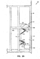
Figure 2a illustrates a detailed view of an embodiment of a mechanical actuator, in expanded mode, that can be used in connection with an example embodiment of the invention. -
Figure 3 is an exploded view of an industrial camera and housing that can be used in connection with an example embodiment of the invention. -
Figure 4 illustrates a flowchart of a process control that can be used in connection with an example embodiment of the invention. - In the following detailed description, reference is made to the accompanying drawings that show, by way of illustration, specific embodiments in which the invention may be practiced. These embodiments are described in sufficient detail to enable those skilled in the art to practice the invention. It is to be understood that the various embodiments of the invention, although different, are not necessarily mutually exclusive. For example, a particular feature, structure, or characteristic described herein in connection with one embodiment may be implemented within other embodiments without departing from the scope of the invention. In addition, it is to be understood that the location or arrangement of individual elements within each disclosed embodiment may be modified without departing from the scope of the invention. The following detailed description is, therefore, not to be taken in a limiting sense, and the scope of the present invention is defined only by the appended claims, appropriately interpreted, along with the full range of equivalents to which the claims are entitled. In the drawings, like numerals refer to the same or similar functionality throughout the several views.
-
Figures 1 and2 illustrate an embodiment of a transport system that moves a visible and/or an infrared (IR) camera enclosed in an industrial housing along a rail. While the embodiment ofFigures 1 and2 show a transport system of the invention in connection with an IR camera; those of skill in the art will readily realize that the invention is not limited to an IR camera, but that embodiments of the transport system ofFigures 1 and2 could also transport other pieces of equipment as well. Additionally, while the embodiment ofFigure 1 is discussed in connection with an industrial furnace, those of skill in the art will readily realize that the transport system ofFigures 1 and2 can be used in connection with other pieces of industrial equipment also. Moreover, while the transport system ofFigures 1 and2 is described as operating with a pneumatic system, one of skill in the art will realize that other means of powering the transport system such as electric powered motors in combination with gears, belts, chains, and/or pulleys could also be used. - The support and
transport structure 100 ofFigure 1 has aframe 105. Attached to theframe 105 is a first motion transport system. In an embodiment, the first motion transport system is a pneumatic transport system that consists of arail 110 and atrolley structure 115. In another embodiment, therail 110 is one that is manufactured by Tol-o-matic® of Hamel, Minnesota (www.tolomatic.com). In an embodiment, theframe 105 is attached to the outside of the wall of anindustrial housing 140, and the pneumatic transport system is attached to theframe 105. In one particular embodiment, the wall of theindustrial housing 140 is an outside wall of a furnace. Positioned on top of thetrolley structure 115 is anenclosure 120. Theenclosure 120 contains astepper motor 126 and ashaft 127. The stepper motor and shaft havewheels wheels other means 130. (SeeFigure 2 ). - Connected to the
enclosure 120 via acable 136 is acontrol box 137 that houses a control processor and electrical and pneumatic controls. Also attached to thecontrol box 137 is areservoir 138 for the storage of pneumatic air. A secondindustrial housing 135 is connected to the end ofshaft 127 opposite that of thewheel 129. In an embodiment, theindustrial housing 135 encloses a camera, such as an IR camera. Also attached to theframe 105 is a second motion transport system that, like the first motion transport system, may be a pneumatic transport system. In the embodiment ofFigure 1 , such a pneumatic transport system has arail 150, asecond trolley structure 156, and adoor 154. The second trolley structure is attached to thedoor 154 withattachments 157 and tension springs 153 that attach thedoor 154 to the pneumatic transport system via adoor trolley structure 156. Thedoor trolley 156 inFigures 1 and2 is depicted in generic form to indicate that several connecting mechanisms known in the art could be used to connect thedoor 154 to thetrolley structure 156. In one particular embodiment, the details of which are illustrated inFigures 1a and2a , theattachment 157 includes a triangular bracket 157a and a roller 158b to connect the bracket 157a to thetrolley structure 156. The door covers anopening 160 in the industrial housing wall 140 (Figure 2 ). - The
transport system 100 supports and transports theindustrial housing 135 into and out of an industrial environment. In an embodiment, the industrial environment is a furnace, and theindustrial housing 135 encloses an IR camera. An exploded view of an embodiment of anindustrial housing 135 and an IR camera is illustrated inFigure 3 . Thehousing 135 has abottom plate 171, and encloses acamera 170. Anopening 172 receives the camera lens (not shown inFigure 3 ) that is attached to thecamera 170. The camera lens is enclosed and protected by awindow 173 andlens housing 174 that is attached to the industrial housing. Acoupling unit 175 attaches onto the housing wall, and serves to connect thehousing 135 to theshaft 127. In an embodiment, theindustrial housing 135 is manufactured out of hardened stainless steel, and thewindow 173 is made out of sapphire. In different embodiments, the lens attached to the camera may be a wide angle lens, a narrow angle lens, and/or a telescoping lens. - Referring now to
Figure 2 , thedoor 154 has been moved in the direction of arrow A. As will be explained in detail in connection withFigure 4 , the movement of the door along arrow A occurs by activating the second pneumatic transport system, which movesdoor trolley 156 and thedoor 154 alongrail 150, thereby exposingopening 160 in theindustrial wall 140. Referring now toFigure 2A , in an embodiment,attachments 157 A&B and tension springs 153 A&B secure thedoor 154 to thedoor trolley 156. Theattachment 157 betweendoor trolley 156 and thedoor 154 has compression springs 157C to ensure a tight seal between thedoor 154 and thewall 140 when thedoor trolley 156 is in the lowered position. Tension springs 153 A&B betweendoor 154 anddoor trolley 156 is to ensure the door is held against the door trolley and away from thewall 140 when the door trolley is in the upper position. When thedoor trolley 156 first begins to rise, the compression spring force ofattachments 157 A&B releases and tension springs 153A&B pull door 154 towarddoor trolley 156 and away from thewall 140. This ensures that there is no interference between thedoor 154 and thewall 140 or other structure. As thedoor trolley 156 continues to raise, both thedoor trolley 156 anddoor 154 move in the direction of arrow A. When thedoor 154 anddoor trolley 156 are lowered by activating the second pneumatic transport system, the door first moves with the door trolley down in the direction of arrow B untilroller 158A, which is fixed todoor 154, contacts the horizontal portion of the frame 105a. Thetrolley 156 continues to move down while thedoor 154 can not, causing compression spring loadedattachment 157B to move the door toward theindustrial wall 140. The detail of theattachment 157B,roller 158A andtension spring 153B is illustrated inFigures 1a and2a . Referring toFigure 1a , as thedoor trolley 156 is moved down by the second pneumatic transport system with theroller 158B preventing any further movement in the direction of arrow B,attachment 157A pushes thedoor 154 away from thedoor trolley 156 towardwall 140. When thedoor trolley 156 is raised by the second pneumatic system, thetension spring 153A first pulls thedoor 154 back away from theindustrial wall 140 and thendoor trolley 156 anddoor 154 move together in the direction of arrow A. In situations in which theindustrial housing 140 is cylindrical-like in shape, or the surface of a flat housing wall is not perfectly planar, an adapter can be welded or otherwise coupled onto the wall of the industrial housing. The surface of the adapter that contacts thedoor 154 can then be machined to accurately mate with the door. -
Figure 2 further shows thatenclosure 120,shaft 127, andhousing 135 have been moved alongrail 110 via the activation of the first pneumatic transport system. Thehousing 135 itself has been moved throughopening 160 into theindustrial housing 140.Figure 2 further illustrates that theindustrial housing 135 has been rotated from a home position as illustrated inFigure 1 (as determined by the direction that thewindow 173 andlens housing 174 is pointed), to a deployed position as illustrated inFigure 2 . In another embodiment, the industrial housing is attached to theshaft 127 by a mechanism that allows theindustrial housing 135 to tilt when it is in theindustrial housing 140. - In an embodiment, the
transport structure 100 is connected to a processor housed incontrol box 137 that controls the functions of thetransport system 100. A flowchart outlining an embodiment of the control process is illustrated inFigure 4 . InFigure 4 , thecontrol process 400 at block 405 (a process control computer) transmits a signal to thecamera 170 to determine the temperature of the camera. If the temperature of the camera is too high, for example because of a recent incursion into a furnace, the process control will not move the camera into the furnace. In one embodiment, a timed loop is programmed into the processor logic to poll the temperature again, and see if the temperature is low enough to be inserted into the furnace. In other embodiments, the insertion of the camera is on a timed and scheduled basis, and the system then waits for the next scheduled time to insert the camera into the furnace. In yet another embodiment, an operator provides a command to the processor to move the camera into the furnace, and if insertion does not occur because the temperature of the camera is too high, the operator can wait before reissuing the command. - In an embodiment, if the temperature of the camera is found to be within operating conditions in
block 410, image and rotation angle commands are transmitted from the camera to a programmable logic controller (PLC) housed in control box 137 (block 412). The image command readies theIR camera 170 for capturing images, and the rotation command is sent to the PLC which communicates with the stepper motor controller, housed incontrol box 137, which rotates the camera so that thewindow 173 andlens housing 174 will be pointed in the desired direction at 427. At 415, the PLC checks to see if theindustrial housing 135, theenclosure 120, and thecontrol box 137 have been successfully purged. Apurge system 139, housed incontrol box 137, establishes a positive pressure in theenclosure 120, thecontrol box 137, and thehousing 135. This positive pressure keeps contaminants from leaking into these structures. If the Purge is OK, the PLC then checks inblock 420 whether thecamera 135 is out and thedoor 154 is closed. If the camera is out and thedoor 154 to thehousing 140 is closed, the PLC checks inblock 425 to see if thecamera window 173 andlens housing 174 are located in the home position. If the camera is home, signals are then sent to the stepper motor at 427 so that the camera is rotated the desired number of degrees to the desired angle (i.e. the deployed position). If the purge was not OK inblock 415, or the camera was not out and/or the door was not closed inblock 420, or the stepper motor was not in a home position inblock 425, a variable representing the health or status of the PLC is set to zero and sent to the camera inblock 430, and the camera communicates a PLC health error indication to the process computer. - In
block 440, the processor sends a signal to energize a pneumatic valve which opens thedoor 154 that seals thehousing 140. Inblock 445, the processor checks to see if the door successfully opened. If the door did not open successfully, the PLC health status is set to zero at 430, and the PLC sends the information to the camera. If the door successfully opened, the first pneumatic transport system is energized at 447, and thehousing 135 andcamera 170 are moved through thehousing wall 140. The processor then determines if the camera was moved into the housing successfully at 450. If it was not, the PLC status is once again set to zero. If the processor determines that the camera was moved into the furnace successfully, images are captured by the camera at 460. The camera then communicates with the process computer inblock 405 and transfers the images. These images may be transmitted via wired or unwired means. Then, after a short time in the furnace at 465 (three seconds in one embodiment), the PLC sends a signal to the first pneumatic transport system at 470 to energize the valve again so that the housing and camera are removed from the furnace. The PLC checks to see if the camera was successfully removed from the furnace at 475. If it was, not, the PLC status is set to zero. If the camera was successfully removed from the furnace, the close door valve of the second pneumatic transport system is reenergized at 480, and thedoor 154 is closed. The PLC checks to see if the door was successfully closed (485), and if it was not, PLC status is set to zero. - When the transport system senses any of the problems outlined above, (e.g. the
door 154 did not successfully close at 485), or any other problems such as loss of electrical power or loss of pneumatic pressure, the processor status is set to zero and the system goes into a failsafe state. If instrument air is lost in the failsafe state, the pneumatic air in thereservoir 138 is used by the system to remove the camera from the furnace (if the camera is in the furnace wen the problem occurs), and to shut the door 154 (if once again the door is open when the problem occurs). This failsafe operation prevents the situation where the furnace door remains open because of a failure of some part of the system. In an embodiment that uses an electric motor to move saidindustrial housing 135 and saiddoor 154, an alternative power supply, such as a battery or gas-powered generator, could be used to put the system into the failsafe mode.
Claims (9)
- An apparatus comprising:a frame (105);a first pneumatic system (110, 115, 137) attached to said frame; a second pneumatic system (137, 150, 156) attached to said frame;an industrial housing (135) connected to said first pneumatic system;a motor (126), said motor connected to said first pneumatic system and said industrial housing;a shaft (127), said shaft connecting said motor to said industrial housing;a programmable logic controller (137) coupled to said first pneumatic system and said second pneumatic system, said programmable logic controller housed in a control box (137);an enclosure (120) to house said motor;a door (154) connected to said second pneumatic system;a purge system (139) to establish a positive pressure within said control box, said enclosure that houses said motor, and said industrial housing; anda piece of industrial equipment (140), said frame attached to said piece of industrial equipment.
- The apparatus of claim 1, wherein said industrial equipment comprises a furnace (140).
- The apparatus of claim 1 or claim 2, further comprising a camera (170) contained within said industrial housing (135), wherein said camera comprises an infrared camera including a wide angle lens (173).
- The apparatus of any one of the preceding claims, further comprising:a second trolley (156) attached to said second pneumatic system (137, 150); andan actuator (157) connecting said second trolley to said door (154);wherein said second pneumatic system (137, 150, 156) causes said door to move in a first direction (A) and said actuator causes said door to move away from said industrial equipment (140); and
further wherein said second pneumatic system causes said door to move in a second direction (B) and said actuator causes said door to move towards said industrial equipment. - The apparatus of any one of the preceding claims, wherein said industrial housing (135) comprises hardened stainless steel.
- The apparatus of claim 1,
wherein said first pneumatic system includes a first rail (110) and said second pneumatic system includes a second rail (150), said frame, said first rail and said second rail attached to the piece of industrial equipment (140);
wherein the motor (126) is slidably coupled to said first rail; and
the door (154) is slidably coupled to said second rail, said door for covering an opening (160) on said industrial equipment;
the apparatus further comprising an infrared camera (170) positioned within said industrial housing;
said first pneumatic system further including means (115) to move said motor along said first rail and said second pneumatic system further including means (156) to move said door along said second rail; and
a processor (137), said processor coupled to said motor, said door, said means to move said motor along said first rail, and said means to move said door along said second rail. - The apparatus of claim 6, wherein said means (115) to move said motor along said first rail and said means (156) to move said door along said second rail comprise a motion transport system.
- The apparatus of claim 6, wherein said means (115) to move said motor along said first rail and said means (156) to move said door along said second rail comprise a pneumatic system.
- A method comprising:determining (410) a temperature of a camera (170);rotating (427) said camera to a deployed position;applying (415) a positive internal pressure to said camera;opening (440) a door (156) covering an opening in a furnace;moving (447) said camera, using a transport system (110, 115), into said furnace;capturing (460) images with said camera inside of said furnace;removing (470) said camera from said furnace;transmitting (448) said images to a processor;closing (480) said door after said camera has been removed;verifying (485) that said door has closed;detecting (430) an error condition;withdrawing (470) said camera from said furnace; andclosing (480) said door.
Applications Claiming Priority (2)
| Application Number | Priority Date | Filing Date | Title |
|---|---|---|---|
| US11/322,528 US7641402B2 (en) | 2005-12-30 | 2005-12-30 | Transport system for monitoring industrial process |
| PCT/US2006/048348 WO2007078933A1 (en) | 2005-12-30 | 2006-12-19 | Transport system for monitoring industrial processes |
Publications (2)
| Publication Number | Publication Date |
|---|---|
| EP1969433A1 EP1969433A1 (en) | 2008-09-17 |
| EP1969433B1 true EP1969433B1 (en) | 2010-04-14 |
Family
ID=38042732
Family Applications (1)
| Application Number | Title | Priority Date | Filing Date |
|---|---|---|---|
| EP06845768A Ceased EP1969433B1 (en) | 2005-12-30 | 2006-12-19 | Transport system for monitoring industrial processes |
Country Status (6)
| Country | Link |
|---|---|
| US (3) | US7641402B2 (en) |
| EP (1) | EP1969433B1 (en) |
| JP (1) | JP4944900B2 (en) |
| CN (1) | CN101395546B (en) |
| DE (1) | DE602006013710D1 (en) |
| WO (1) | WO2007078933A1 (en) |
Families Citing this family (12)
| Publication number | Priority date | Publication date | Assignee | Title |
|---|---|---|---|---|
| US7641402B2 (en) * | 2005-12-30 | 2010-01-05 | Honeywell International Inc. | Transport system for monitoring industrial process |
| DE102007048684B4 (en) * | 2007-10-10 | 2010-09-09 | Polysius Ag | laboratory system |
| US8023818B2 (en) * | 2008-07-24 | 2011-09-20 | Fluke Corporation | Articulating infrared window |
| US8199193B2 (en) * | 2008-10-30 | 2012-06-12 | Caskol, Llc | Video camera inspection system for roller hearth heat treating furnaces and the like |
| US9509923B2 (en) * | 2012-01-10 | 2016-11-29 | General Electric Company | Continuous infrared thermography monitoring and life management system for heat recovery steam generators |
| US9127891B2 (en) * | 2013-07-10 | 2015-09-08 | Honeywell International, Inc. | Furnace visualization |
| EP2887328B1 (en) * | 2013-12-19 | 2016-04-20 | Axis AB | Monitoring devices slidably mounted on a rail releasably locked to predetermined positions |
| EP3168819B1 (en) | 2015-11-16 | 2017-12-27 | Axis AB | Protective dome for monitoring camera system |
| WO2018002683A1 (en) * | 2016-06-30 | 2018-01-04 | Centre De Pyrolyse Du Charbon De Marienau | Device for measuring a shape of a wall portion of an oven, such as a coke oven |
| CN107390596B (en) * | 2017-08-30 | 2019-07-09 | 合肥福瞳光电科技有限公司 | A kind of smart office doorplate management system |
| US11802732B2 (en) | 2021-02-26 | 2023-10-31 | Rtx Corporation | Systems and methods for vacuum furnace post-processing |
| CN116087221B (en) * | 2023-03-02 | 2023-09-08 | 东北电力大学 | Air cooler dust accumulation state detection device and method based on computer vision |
Family Cites Families (17)
| Publication number | Priority date | Publication date | Assignee | Title |
|---|---|---|---|---|
| US3021386A (en) * | 1960-03-30 | 1962-02-13 | Gen Electric | Boiler port viewing system |
| US4131914A (en) * | 1975-09-23 | 1978-12-26 | Bricmont & Associates, Inc. | Method and apparatus for inspecting refractory lining in coke oven chambers and the like |
| FR2544540B1 (en) * | 1983-04-13 | 1985-10-25 | Commissariat Energie Atomique | MACHINE FOR EXAMINING A NUCLEAR REACTOR FUEL ASSEMBLY |
| US4815757A (en) * | 1986-04-24 | 1989-03-28 | Hamilton Mark L | Rapid development surveillance vehicle and method |
| US4913458A (en) * | 1986-04-24 | 1990-04-03 | Hamilton Mark L | Surveillance vehicle control system |
| JP3175391B2 (en) * | 1993-03-16 | 2001-06-11 | 株式会社日立製作所 | Monitoring device inside containment vessel with shield |
| JP3042758B2 (en) * | 1995-02-17 | 2000-05-22 | 川崎製鉄株式会社 | Method and apparatus for diagnosing furnace wall in coke oven carbonization chamber |
| JP2872166B2 (en) * | 1996-11-29 | 1999-03-17 | 建一 今野 | Monitor camera transport device using compressed air |
| US5835806A (en) * | 1997-02-26 | 1998-11-10 | The United States Of America As Represented By The Secretary Of Agriculture | Passive self-contained camera protection and method for fire documentation |
| US6229563B1 (en) * | 1998-07-14 | 2001-05-08 | Fosbel International Limited | Camera insertion into a furnace |
| JP2000180584A (en) * | 1998-12-21 | 2000-06-30 | Hitachi Ltd | Monitoring device and monitoring system |
| JP2000295502A (en) * | 1999-04-06 | 2000-10-20 | Asahi Glass Co Ltd | Furnace observation device |
| JP3770073B2 (en) * | 2000-10-30 | 2006-04-26 | 株式会社日立製作所 | Remote mobile robot |
| DE60235963D1 (en) | 2001-02-16 | 2010-05-27 | Toyoda Automatic Loom Works | CAMERA LIFTING DEVICE AND LOAD HANDLING ARRANGEMENT OF A LIFTING WAGON AND LIFTING WAGON |
| KR100467747B1 (en) * | 2001-09-01 | 2005-01-26 | 주식회사 영국전자 | Automatic retract device of vision tube for furnace monitoring |
| JP3875659B2 (en) | 2003-07-25 | 2007-01-31 | 株式会社東芝 | Camera device and robot device |
| US7641402B2 (en) * | 2005-12-30 | 2010-01-05 | Honeywell International Inc. | Transport system for monitoring industrial process |
-
2005
- 2005-12-30 US US11/322,528 patent/US7641402B2/en not_active Expired - Fee Related
-
2006
- 2006-12-19 EP EP06845768A patent/EP1969433B1/en not_active Ceased
- 2006-12-19 DE DE602006013710T patent/DE602006013710D1/en active Active
- 2006-12-19 JP JP2008548605A patent/JP4944900B2/en not_active Expired - Fee Related
- 2006-12-19 WO PCT/US2006/048348 patent/WO2007078933A1/en not_active Ceased
- 2006-12-19 CN CN2006800536084A patent/CN101395546B/en not_active Expired - Fee Related
-
2008
- 2008-08-04 US US12/185,655 patent/US8562227B2/en not_active Expired - Fee Related
-
2009
- 2009-10-08 US US12/576,072 patent/US7832946B2/en not_active Expired - Fee Related
Also Published As
| Publication number | Publication date |
|---|---|
| EP1969433A1 (en) | 2008-09-17 |
| DE602006013710D1 (en) | 2010-05-27 |
| US20080291270A1 (en) | 2008-11-27 |
| US8562227B2 (en) | 2013-10-22 |
| JP2009522548A (en) | 2009-06-11 |
| US7641402B2 (en) | 2010-01-05 |
| CN101395546A (en) | 2009-03-25 |
| WO2007078933A1 (en) | 2007-07-12 |
| US7832946B2 (en) | 2010-11-16 |
| CN101395546B (en) | 2011-08-10 |
| US20070154205A1 (en) | 2007-07-05 |
| US20100021154A1 (en) | 2010-01-28 |
| JP4944900B2 (en) | 2012-06-06 |
Similar Documents
| Publication | Publication Date | Title |
|---|---|---|
| US8562227B2 (en) | Transport system for monitoring industrial processes | |
| CN106494847A (en) | Belt conveyer cruising inspection system | |
| CN109187063A (en) | Detection device and detection method for obstacle avoidance function of robot | |
| JP4157466B2 (en) | Valve leak detection system | |
| KR101663653B1 (en) | Management device of facility and safety in construction location by using PLC and Wi-Fi | |
| CN213616681U (en) | Cable trench inspection robot system | |
| JP2006120820A (en) | Thin substrate processing apparatus and thin substrate transfer apparatus | |
| CN2692662Y (en) | Smoke detector | |
| CN113119061B (en) | Inspection robot and control method thereof | |
| CN102686369B (en) | Assembly for diagnosing a device with moving parts | |
| JP2003331369A (en) | Gas detection device and gas detection system | |
| JP6316739B2 (en) | Valve actuator | |
| CN119125619A (en) | An electronic product performance testing device and analysis system based on artificial intelligence | |
| KR100228137B1 (en) | Robotic Cable Inspection System | |
| CN215262366U (en) | Two-dimensional force detection mechanism and robot | |
| JPH08240069A (en) | Automatic door opening / closing device for power supply unit | |
| CN115962372A (en) | Pipeline investigation robot for suspension inspection and suspension inspection method | |
| CN113376065A (en) | Glass particle inspection apparatus | |
| CN215886870U (en) | Access control system with monitoring function | |
| CN118739974B (en) | A non-contact automatic temperature monitoring system and method for motors | |
| CN114310937A (en) | Explosion-proof inspection robot capable of being monitored in integrated mode | |
| JPS59138996A (en) | Method of setting up inside of hot cell | |
| CN215894441U (en) | Analyzer with automatic uncovering function | |
| CN119602477A (en) | A transmission line status monitoring system based on Beidou communication | |
| CN212228462U (en) | Automatic grain sampler for closed assay |
Legal Events
| Date | Code | Title | Description |
|---|---|---|---|
| PUAI | Public reference made under article 153(3) epc to a published international application that has entered the european phase |
Free format text: ORIGINAL CODE: 0009012 |
|
| 17P | Request for examination filed |
Effective date: 20080627 |
|
| AK | Designated contracting states |
Kind code of ref document: A1 Designated state(s): DE FR GB |
|
| RIN1 | Information on inventor provided before grant (corrected) |
Inventor name: ALVAREZ, MANUEL, S. Inventor name: LANE, CHARLES, E. III Inventor name: SHEARD, JUSTIN, M. Inventor name: HAIN, LARRY, A. Inventor name: VOLNA, WILLIAM, M. Inventor name: KOCANDA, ROBERT, F. Inventor name: SCHMIDT, ROGER, N. |
|
| RIN1 | Information on inventor provided before grant (corrected) |
Inventor name: SCHMIDT, ROGER, N. Inventor name: LANE, CHARLES, E. III Inventor name: SHEARD, JUSTIN, M. Inventor name: VOLNA, WILLIAM, M. Inventor name: HAIN, LARRY, A. Inventor name: KOCANDA, ROBERT, F. Inventor name: ALVAREZ, MANUEL, S. |
|
| 17Q | First examination report despatched |
Effective date: 20081106 |
|
| DAX | Request for extension of the european patent (deleted) | ||
| RBV | Designated contracting states (corrected) |
Designated state(s): DE FR GB |
|
| GRAP | Despatch of communication of intention to grant a patent |
Free format text: ORIGINAL CODE: EPIDOSNIGR1 |
|
| GRAS | Grant fee paid |
Free format text: ORIGINAL CODE: EPIDOSNIGR3 |
|
| GRAA | (expected) grant |
Free format text: ORIGINAL CODE: 0009210 |
|
| AK | Designated contracting states |
Kind code of ref document: B1 Designated state(s): DE FR GB |
|
| REG | Reference to a national code |
Ref country code: GB Ref legal event code: FG4D |
|
| REF | Corresponds to: |
Ref document number: 602006013710 Country of ref document: DE Date of ref document: 20100527 Kind code of ref document: P |
|
| PLBE | No opposition filed within time limit |
Free format text: ORIGINAL CODE: 0009261 |
|
| STAA | Information on the status of an ep patent application or granted ep patent |
Free format text: STATUS: NO OPPOSITION FILED WITHIN TIME LIMIT |
|
| 26N | No opposition filed |
Effective date: 20110117 |
|
| REG | Reference to a national code |
Ref country code: FR Ref legal event code: PLFP Year of fee payment: 10 |
|
| REG | Reference to a national code |
Ref country code: FR Ref legal event code: PLFP Year of fee payment: 11 |
|
| REG | Reference to a national code |
Ref country code: FR Ref legal event code: PLFP Year of fee payment: 12 |
|
| PGFP | Annual fee paid to national office [announced via postgrant information from national office to epo] |
Ref country code: FR Payment date: 20171229 Year of fee payment: 12 |
|
| PGFP | Annual fee paid to national office [announced via postgrant information from national office to epo] |
Ref country code: GB Payment date: 20171228 Year of fee payment: 12 |
|
| PGFP | Annual fee paid to national office [announced via postgrant information from national office to epo] |
Ref country code: DE Payment date: 20180228 Year of fee payment: 12 |
|
| REG | Reference to a national code |
Ref country code: DE Ref legal event code: R119 Ref document number: 602006013710 Country of ref document: DE |
|
| GBPC | Gb: european patent ceased through non-payment of renewal fee |
Effective date: 20181219 |
|
| PG25 | Lapsed in a contracting state [announced via postgrant information from national office to epo] |
Ref country code: DE Free format text: LAPSE BECAUSE OF NON-PAYMENT OF DUE FEES Effective date: 20190702 Ref country code: FR Free format text: LAPSE BECAUSE OF NON-PAYMENT OF DUE FEES Effective date: 20181231 |
|
| PG25 | Lapsed in a contracting state [announced via postgrant information from national office to epo] |
Ref country code: GB Free format text: LAPSE BECAUSE OF NON-PAYMENT OF DUE FEES Effective date: 20181219 |