JP3770073B2 - Remote mobile robot - Google Patents
Remote mobile robot Download PDFInfo
- Publication number
- JP3770073B2 JP3770073B2 JP2000334910A JP2000334910A JP3770073B2 JP 3770073 B2 JP3770073 B2 JP 3770073B2 JP 2000334910 A JP2000334910 A JP 2000334910A JP 2000334910 A JP2000334910 A JP 2000334910A JP 3770073 B2 JP3770073 B2 JP 3770073B2
- Authority
- JP
- Japan
- Prior art keywords
- cable
- drum
- robot
- robot body
- guide pole
- Prior art date
- Legal status (The legal status is an assumption and is not a legal conclusion. Google has not performed a legal analysis and makes no representation as to the accuracy of the status listed.)
- Expired - Fee Related
Links
Images


Classifications
-
- Y—GENERAL TAGGING OF NEW TECHNOLOGICAL DEVELOPMENTS; GENERAL TAGGING OF CROSS-SECTIONAL TECHNOLOGIES SPANNING OVER SEVERAL SECTIONS OF THE IPC; TECHNICAL SUBJECTS COVERED BY FORMER USPC CROSS-REFERENCE ART COLLECTIONS [XRACs] AND DIGESTS
- Y02—TECHNOLOGIES OR APPLICATIONS FOR MITIGATION OR ADAPTATION AGAINST CLIMATE CHANGE
- Y02E—REDUCTION OF GREENHOUSE GAS [GHG] EMISSIONS, RELATED TO ENERGY GENERATION, TRANSMISSION OR DISTRIBUTION
- Y02E30/00—Energy generation of nuclear origin
- Y02E30/30—Nuclear fission reactors
Landscapes
- Monitoring And Testing Of Nuclear Reactors (AREA)
- Manipulator (AREA)
Description
【0001】
【発明の属する技術分野】
本発明は遠隔移動ロボットに関し、特に原子力施設などの通常人間の入ることのできない部屋の狭隘部の点検などの作業に適した遠隔移動ロボットである。
【0002】
【従来の技術】
従来、特開昭58−76799号「原子炉格納容器内監視装置」あるいは特開昭60−230094号「原子炉監視装置」にあるようにTVカメラなどのセンサを搭載して移動する監視点検ロボットの概念は示されていた。また、特開平05−065704号「高架橋点検装置」にあるように移動車に伸縮ブーム,旋回機構,アーム機構などを備えて先端のセンサの位置と向きを変えるような作業装置の概念は示されていた。
【0003】
【発明が解決しようとする課題】
しかし、狭隘な場所において、安全,確実に狭隘部の点検等の作業ができて、かつ必要最小限の機器から構成する単純な機構とすることについてはあまり考慮されていなかった。
【0004】
本発明の目的は、狭隘な場所において、安全,確実に狭隘部の点検などの作業ができて、かつ必要最小限の機器から構成する単純なロボットを提供することにある。
【0005】
【課題を解決するための手段】
本発明の課題を解決するための手段の基本的な構成要件は、ロボット本体が走行レールに沿って走行する台車を有する走行型ロボットにおいて、ロボット本体から出ているケーブルを引っ張っているドラムを固定局側に設け、水平や垂直に曲がっている走行レールのコーナー部には、前記走行レールから外れて前記コーナーの内側に、前記台車がコーナー部を曲がる時にケーブルが引っかかりガイドされるようにガイドポールを配置することである。
【0026】
本発明の基本的な構成要件によれば、ロボット本体が走行レールに沿って走行する台車を有する走行型のロボット本体から出ているケーブルを引っ張っているドラムを固定局側に設けるので、ケーブルはたるんで周囲の障害物にからまることはない。また、走行レールのコーナー部には台車が曲がる時にケーブルがガイドされるようにガイドポールを配置することにより、ケーブルがガイドポール以外の機器にこすれたり、からまったりすることはない。従って、狭隘な場所においても、安全,確実にロボット本体は奥へ入っていくことが可能となり、狭隘部の点検などの作業が可能となる。また、設備としてもガイドポールをところどころに設けるだけなので、単純な設備で必要最小限の機器から構成することが可能となる。
【0048】
【発明の実施の形態】
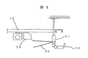
以下に本発明の実施例を図面を用いて説明する。図1の(a)図と図1の(b)図は本発明を適用した走行型ロボットの基本的な一実施例を示す。
【0049】
ロボット本体20はレール10に沿って移動可能な台車を有しており、ロボット本体20からはケーブル30が出ていてドラム40に巻き取られている。ケーブル30はロボット本体と操作部間の通信用ケーブルでもよいし、映像を伝送するケーブルでもよいし、映像と制御情報を重畳させた信号ケーブルでもよい。また、通信だけでなくロボット本体の動力供給を兼ねてもよい。
【0050】
図1の(b)ではロボット本体20はシャッタ109を開いて、固定局側の挿入装置100から可動レール11が固定レール10に接続してロボット本体20が可動レール11から固定レール10へ乗り移る。
【0051】
ケーブル30は常にドラム40に低張力で巻き取られている。ロボット本体20が前進すればドラム40はケーブルを送り出し、ロボット本体20が後退すればたるんだケーブル30はドラム40に巻き取られる。ドラム40は常に低張力でケーブル30を巻き取っているので、ロボット本体20がそのような動作をすればケーブル30は自動的にドラム40に巻き取られたり、送り出されたりする。
【0052】
図1の(b)図は部屋の入り口開口部1付近の状況であるので、ケーブル30は直線的に張られているが、レール10が直線ばかりでなく、水平や垂直に曲がっているレールルートもある。その場合には、たとえば図1の(a)図のように本発明のガイドポール50をレール10のコーナー部に設けるとロボット本体20がコーナー部を曲がるとケーブル30はガイドポール50に引っかかりガイドされることになる。
【0053】
このようなガイドポール50をレール10の曲がりコーナー部に設けることで複雑に曲がったレールルート部屋もケーブルを絡ませたり、断線させないで、安全確実に処理することが可能となる。
【0054】
図2は本発明を適用したケーブル30の断面構造の一例である。たとえば、張力に耐える強度部材としてワイヤ33を中心に配置して、その周辺に絶縁導体32を配置した構造となっている。このケーブル断面で最外周部の被覆31に低摩擦部材としてテフロン材を用いた一実施例である。
【0055】
本実施例のようなケーブルが図1の(a)図のようなガイドポール50に引っかかり滑っても外表面がテフロンで低摩擦係数なので、すべり抵抗が小さくなるので、ロボット本体20の牽引量とかドラム40の巻き取り力を小さくしてコンパクトにすることが可能となる。
【0056】
図3は低摩擦抵抗にしたガイドポールの基本的な一実施例を示す。ガイドポール軸心50の外側に回転部材51を設けてある。ケーブル30は回転部材51に接するのでケーブルが動くと回転部材51が軸心50の周りを回転する。回転部材51は滑らかに回転可能としておくことにより、ケーブルが滑らかにガイドされる。
【0057】
これも同様にケーブルの牽引力を小さくできるので、ロボット本体とかドラムを小さくできる。ここで、回転部材51は数珠上の形状で軸心50の曲がったところもケーブルが直接軸心50に接触するスキマがないようにしてもよいし、特殊な形状にしてケーブルが必ず当たるような工夫をするとよい。
【0058】
また、垂直曲がりとか水平曲がりとして予めケーブルがかかる位置がいつも決まっている場所についてはその個所だけにケーブルを回転しながら滑らかにガイドする回転部材を設けるようにしてもよい。
【0059】
図4はケーブルの張力を検出する検出センサをもうけてドラムを制御する場合の基本的な一実施例を示す。ケーブル張力センサはロボット本体20側に設ける場合とドラム40側に設ける場合がある。当然、両方に設けてもよい。
【0060】
ロボット本体側の一例ではケーブル30がレバー22に保持されていて、バネ23でレバー22とケーブルはケーブル30の張力とつり合って引かれている構造である。ここで、レバー22の動きは回転21の回転角度として検出されればその回転角度はばね23と釣りあった張力の大きさを示すこととなる。
【0061】
一方、ドラム側の一実施例ではケーブル30のかかっている滑車41の反力をロードセル42で検出するものである。この滑車41の反力をロードセル42で検出することによりケーブル張力を検出することができる。ケーブル30の張力が検出できれば、その張力が一定となるようにドラム40を回転駆動制御させることが可能となり、張力を直接検出して制御しているので、張力を安定に一定に保ちながら低張力制御を実現可能となる。
【0062】
図5はロボット本体の移動距離に応じてドラムの駆動制御を行う制御系の基本的な一実施例を示す。レール10に沿って移動するロボット本体20は途中の曲がりレール部でケーブル30はガイドポール50a,50b,50cでガイドされるようになっている。ケーブル30がガイドされてドラム40に巻きついている。
【0063】
ロボット本体20にはレール10の上で現在どこにいるかのセンサを有しており、そのセンシング情報はケーブル30からドラム40に設けられたスリップリング39からロボット制御装置29に通信で送られる。
【0064】
一方、ドラム40の駆動制御はモータ43がアンプドライバ46で駆動されるかドラムの回転数をエンコーダ44で検出してドラム制御装置45にフィードバックがかかるようになっている。
【0065】
これでドラムの回転数(回転角度)の制御が安定に行うことができるようになる。その上でロボット本体の制御装置29ではロボット本体20のレール10の上での現在位置情報をもっているので、その情報をドラム制御装置45へ入力可能とすることで、ロボットの現在位置に応じてドラムの巻き取り,送り出し制御が可能となる。
【0066】
ここで、ロボット本体20のレール10の上での現在位置はレール10の長さに相当して、ケーブル30の長さはガイドポール50a,50b,50cのガイドされたケーブルの全長であり、レール長とは必ずしも一致しないので、予めロボット本体の現在位置とその位置でのケーブル長の関係対応データをレールルートごとに用意しておくことによって、ロボット現在位置から必要なケーブル長に即座に換算できるので、そのケーブル長に必要なドラムの回転角度制御を行うようにするのがよい。この対応データはロボット制御装置29に設けてもよいし、ドラム制御装置45に設けてもよい。
【0067】
図6はドラム制御をロボット本体の位置情報とケーブル張力情報の両方で行う場合の基本的な実施例を示す。ロボット本体20側のケーブル張力はレバー22と回転角度センサ21で検出して、その結果はケーブル30を介して通信でロボット制御装置29に送信されるようにしてロボット制御装置29からロボットの位置情報と同様にドラム制御装置45に送られるようにする。
【0068】
ドラム側の張力は滑車41の反力をロードセル42で検出してそのデータは直接にドラム制御装置45に入力されるようにする。ここで、ドラム制御装置はロボット20の現在位置情報に基づく必要ケーブル長を送り出すとともにロボット側のケーブル張力とドラム側のケーブル張力を常に検出しながら、異常に高い張力がケーブルにかからないようにドラムの回転制御を必要に応じて切り替えるようにする。
【0069】
それによって、安全確実なケーブルの巻き取り,送り出し制御が可能となる。さらに、ドラム制御装置はロボット制御装置からロボット20への動作指令を事前にあるいは同時にもらうことで、ドラム40の動作遅れを予め予想した制御で補うような応答性のよいドラム制御を行ってもよい。
【0070】
図7は本発明の視覚装置を設けた伸縮アーム型マニピュレータの一実施例を示す。ロボット挿入部100は部屋の中に開口部1から伸縮アーム200aと200bからなるアームを挿入した状態を示している。
【0071】
各アーム200aと200bは伸縮ポールなので伸び縮みするほか、回転も可能な構造で2本のアームのつなぎ部の関節では上下左右に回転する構造をもっていて先端の位置を任意遠隔操作できるロボットである。
【0072】
本実施例ではそのアーム先端に視覚装置を設けるが通常ズームレンズ付きのカメラを設けると重量が重たいためアームが大きく撓む。また、アーム駆動時の負荷も大きくなるので、本発明の視覚装置が有効となる。
【0073】
すなわち、本実施例では撮像装置60aには広角レンズ61が付いており、撮像装置60bには望遠レンズ62が付いている2つの視覚装置を設けた。これはCCDなどのカメラは1台が軽く小さいので2つ搭載しても大きな負荷にはならない。また、レンズもズームレンズにするとモータとかレンズ制約条件で軽いものを製作するのは容易ではない。
【0074】
一方、固定焦点レンズであれば、小さく軽量なものを容易に製作できるので、予め必要な2つのレンズをそれぞれ設けた撮像装置を2つ搭載する。これによって、ズームレンズの広角と望遠の機能を兼ね備えた小型軽量な視覚装置を容易に得ることが可能となる。2つの撮像装置の映像は2台のモニタで同時に見てもよいし、切り替えて1台の撮像装置の映像のみを見るようにしてもよい。
【0075】
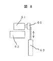
図8は2つ以上のレンズを設けて撮像装置は1台で共用する場合の基本的な一実施例を示す。広角レンズ61と望遠レンズ62を並べて配置して1台の撮像装置60をアクチュエータ63の先に設けて、どちらのレンズにも切り替えて撮像可能なようにしたものである。これは撮像装置が赤外線カメラなど特殊な場合には1台が大きく重くなる場合もあるので、そのような場合に有効は発明である。
【0076】
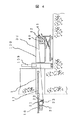
図9は遠隔ロボットの伸縮駆動力を大きくとることのできる伸縮機構部の基本的な一実施例を示す。伸縮ポール201,202,203は筒状の部材で伸縮可能な組み合わせになっているが、その駆動をポール201の先端にベルト204aと204bの端部を固定して、ベルト204aと204bはドラム205aと205bに巻き取られている。
【0077】
ここで、ベルト204aと204bはドラムに巻き取られる方向には曲げやすく、その反対方向には曲げづらい部材とすることで、ドラムには巻き取りやすく、伸ばした状態での剛性は高くすることが可能となる。ベルト204aと204bはコンベックスのように断面が湾曲させた鋼板で作ればこのような特性が得られる。あるいは、チェーンを反対側には折れ曲がらないように詰めを設けてたチェーンを用いてもよい。
【0078】
また、ベルト204aと204bが伸縮ポールの中で伸びていくと背中合わせの部分がたるんでしまって十分な剛性が得られなくなるので、各ポールの根本にガイド部201s,202sを設けておけば、何段の伸縮ポールになっても緩むことなく駆動することができる。
【0079】
ガイド部は各ポールの底板にベルトが通るスリットを設けてもよいし、小さなローラ付きで滑らかにガイドできるものとしてもよい。スリット構造は単純で簡単な方法である。ここで、ドラム205aと205bがモータで駆動制御されるようにすれば、軽くて長い伸縮ポールの駆動機構とすることができる。別にベルトを動かす駆動部を設けてもよい。
【0080】
図10はさらにベルトの合わさる面に押し付けると接着する機能面を設けた場合の基本的な一実施例を示す。はがすときにはドラム205aと205bに巻き取ることで剥がれる。押し出す場合には合わさった直後に加圧ローラ206aと206bで押し付けるようにすることで、機能面が接着するようにしたものである。
【0081】
この構成で加圧ローラ206aと206bを駆動ドラムにすると根本で剛性を高くして駆動ドライブできるようになる。また、ベルトに凹凸を設けたり、穴を設けて、ドライブローラ206aと206bにも凹凸を設けるとかし、ベルトの凹凸や穴にドラムの凹凸をひっかけてより大きな駆動力をベルトに伝えるようにしてもよい。
【0082】
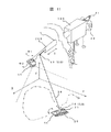
図11は軽快なケーブル処理を可能とした本発明を適用した床面走行型ロボットの基本的な一実施例である。挿入機構100で部屋の開口部1から伸縮アーム200を挿入可能としている。伸縮アームはストロークS分前後に伸縮制御可能である。
【0083】
伸縮アーム200の先端には回転軸θ1,θ2を有するパンチルト機構に視覚センサ65が取り付けてある。こればTVカメラでもよいし、特殊な撮像装置でもよい。回転軸θ1,θ2で部屋の中を撮像することが可能となっている。また、伸縮アーム200には滑車48を介してケーブル30がガイドされて、走行型ロボット本体20とケーブルドラム40につながっている。アーム200は伸縮しなく長いポールを人手で挿入するようにしてもよい。
【0084】
今までは走行型ロボットが床を走るとケーブルが絡まるなどがあって、あまり自由に動かし回すことができなかったが、本発明を適用すれば走行型ロボット本体20は床面を自由に走行させることが可能となる。本発明はロボット本体20のケーブル出口部にケーブルが回転可能なようにたとえばスリップリングを介して取り付け、さらにケーブル30を常に低張力でドラム40で巻き取っておくようにする。
【0085】
それによって、部屋の中のどこを走ってもケーブルはからまらないように常にちょうどよい適切な長さにしておくことが可能となる。また、ロボット本体にランプなどの撮像装置のターゲットとなる部品26を設けておき、それを撮像装置65で撮影してロボット本体の現在位置を求める。
【0086】
図13には撮像画像の一例を示すが、26gがターゲットランプ26の画像である。この画像データから画面内のターゲットの画像内の位置は画像処理で求めることができるので、さらにパンチルト機構の角度θ1,θ2、伸縮アームのストロークSと開口部1の位置と床面の位置関係が既知であれば、床面上のターゲット26(A点)の位置は幾何計算からもとまるので、滑車48(B点)の位置も既知なので、線分ABの長さが求まり、その長さから、ドラム40のケーブル巻き取り,送り出し量を制御するようにすれば、容易に常にちょうどよいケーブル長を保つことができるようになる。
【0087】
位置の検出精度は撮像装置の分解能とかレンズ系の画角によってきまってくるが、装置のセッティング誤差もあるので、撮像装置を挿入後部屋の角のコーナー部等の部屋の基準となる部位を撮影して予め用意しておく部屋のCADデータと対応させて撮像装置の部屋の中での正確な位置と姿勢を最初にキャリブレーションするのがよい。
【0088】
ロボット本体20に設けたターゲット26を撮像装置65で捕らえる位置検出だけでは、たとえばロボット本体20が物の影に入った場合とか場所によって撮像装置に撮影されなくなる時があるので、たとえばジャイロセンサとか壁からの距離を計測する距離センサとか左右の走行車輪あるいはクローラの回転数をカウントするなどの積算型の位置検出データも持っておき、撮像装置で撮影したときに絶対位置として積算型センサによる位置データを構成するやりかたで両方をうまく使い分けることで、ものの影に入っても継続して位置を正しく検出して、その結果により適切なケーブル長を制御できるようになる。
【0089】
図12はロボットの位置検出とケーブルの張力検出を組み合わせた場合の基本的な一実施例を示す。ロボット本体20のターゲット26(A点)から滑車48(B点)を介してケーブル30はドラム40に巻かれているが、途中滑車41の反力をロードセル42で検出可能としている。これでドラム側のケーブル張力を検出することが可能である。
【0090】
ロボット本体の位置データは撮像装置65の画像処理の結果得られるデータもあるが、それはロボット制御装置29あるいはドラム制御装置45に入力され必要なケーブル長が演算されてケーブルドラム40の回転角が制御駆動される。ロボット本体20の積算型センサの情報はケーブル30を介してドラム40のスリップリング39からロボット制御装置29へ送信され、同じようにドラム制御の位置情報として活用される。
【0091】
ケーブル反力を検出するロードセル42の信号はドラム制御装置45へ入力されて、たとえば、ケーブルが物に絡まって計算値ケーブル長では短くなって一時的にケーブルが張った場合には張力が大きくなるので、所定の張力以上になった場合にはドラムケーブルを送り出す制御にするとか、常時一定の張力になるようにドラムを制御して計算したケーブル長と実際のケーブル長が大きく違った場合には何かからまった状態などの異常である可能性があるので、その場合には警報でオペレータに知らせるなどの異常検出制御を行ってもよい。
【0092】
また、オペレータが強制的に低張力制御とケーブル長をあわせる制御と切り替えられるようにしてもよい。何もない空間ではケーブル長を演算して送り出す制御を適用して、柱とか物にケーブルがひかかり直線以外のケーブルパスになる場合にはケーブル長制御でなく、低張力制御に切り替えて運転可能なようにするのがよい。
【0093】
滑車48はドラム40と同期して補助的にモータドライブされるのがケーブルを円滑に送り出し巻き取りが可能となる。この滑車48はドライブするときだけケーブルをはさみ込む機構があるのがよい。この滑車48を常時ケーブルを挟み込んでドライブする場合にはこの部分でケーブル張力を検出するようにするのがよい。
【0094】
図13には撮像画像の一例を示すが、26gがターゲットランプ26の画像である。この画像データから画面内のターゲットの画像内の位置は画像処理で求めることができるので、さらにパンチルト機構の角度θ1,θ2、伸縮アームのストロークSと開口部1の位置と床面の位置関係が既知であれば、床面上のターゲット26(A点)の位置は幾何計算からもとまる。
【0095】
図14,図15は狭隘開口部から挿入する細長いロボットで床面走行に適したロボットの基本的一実施例を示す。走行駆動はすべりなどが少ない左右のクローラ70aと70bで走行する。但し、細長い車体の長いクローラは旋回抵抗が大きくなりスムーズな旋回ができないので、クローラ70aと70bは適度な長さのものとする。
【0096】
それでも走行車体は長く大きいので、その前後の自重は車輪73,74で受ける構成としてある。クローラ70aと70bの駆動制御はモータ71a,71bで左右独立に制御できるようにしておけば旋回動作も可能である。
【0097】
ケーブルのスリップリング25は旋回中心となる台車の中央に配置する。車体の前方にはこの場合TVカメラ60を配置してTVカメラ60aのようにチルト動作可能なように構成する。これによって、床面を軽快に走行して部屋の中の点検が容易にできる走行型ロボットとすることができる。
【0098】
カメラ60が水平の位置になったとき、先端にミラー611が45度傾斜して出るような機構を設ければ床面も同じカメラで点検が可能となる。ランプターゲットはケーブル30がスリップリングで回転してどちら側にくるか不確定なので、ケーブル30がターゲットを隠さないようにランプターゲットを26a,26b,26cの3個を配置して常にどれか2つのランプは撮像されるようにしてその幾何学的配置あるいはランプの色などからロボット本体の位置と姿勢を検出するようにしてもよい。
【0099】
クローラの回転数はエンドレスのポテンショメータ72a,72bを配置してその回転角信号を積算して走行位置を検出する。ポテンショメータを用いるのは放射線に強いからである。これは放射線に強い磁気エンコーダを用いてもよい。もちろん放射線がない環境ではオプティカルエンコーダでもよい。
【0100】
また、本実施例ではケーブル30aをレバー75に回転可能なように保持させておき、レバー75を後ろへ倒すとケーブルは30bにように後方へ出るようにしている。これによって、ケーブルを常に張った状態で走行させるモードとケーブルを後ろにたらして牽引する方式を切り替えて両方式のケーブル処理モードを切り替えて使い分けができるようになる。
【0101】
これは部屋空間に物があって、ケーブルを張ると物とケーブルが干渉するので、どうしてもケーブルを後ろにたるませて牽引しながらものの下へ入っていきたいという場合に切り替えて有効に安全に走行ロボットを遠隔操作できるようになる。
【0102】
図16はマニピュレータに視覚装置を搭載して遠隔での物体へのアクセスを容易にする遠隔ロボットの基本的な一実施例を示す。挿入装置100で開口部1からマニピュレータの伸縮アーム200a,200bは挿入される。マニピュレータの先端には本実施例ではハンド301が取り付けてあり、アクセスした物体をハンドリングできるようになっている。
【0103】
床面500には対象物400が置いてある。マニピュレータのアーム200bの根本には視覚装置650があり、オペレータはこの視覚装置からの情報でマニピュレータを操作してハンドリング作業を行う必要がある。
【0104】
ここで、視覚装置に通常のTVカメラを取り付けた場合、単眼のTVカメラでは距離間隔が得られないためなかなか対象物400に正確にアクセスすることはできない。立体視覚装置を搭載する方法もあるが、オペレータの目が疲れるのが一般的である。そこで、本発明では視覚装置に2次元のスキャニング機構を有する距離計測センサを搭載したものである。当然TVカメラも合わせて搭載してよい。
【0105】
図17は2次元のスキャニング機構を内蔵した放射線の高い雰囲気で使用可能な距離計測センサの基本的な一実施例を示す。視覚装置650の中には耐放射線カメラ651が耐放射線ズームレンズ652を付けて配置されている。
【0106】
ズームレンズの画角は距離計測時には必要な条件パラメータとなるので、設定値は計算機659が管理する。カメラ651の隣にはレーザ光源656から耐放射線光ファイバ655を経由してレーザ光線がミラー654cで反射してスキャンモータ653bのミラー654bで反射してスキャンモータ653aのミラー654aで反射して前方へでていく。
【0107】
ここでスキャンモータ653a,653bを駆動制御するとレーザは距離L離れたところで、幅W×高さHの2次元のスキャンエリア657をスキャニングできるようになっている。ここで、カメラ651の画像にはレーザ光線が写っており、画像中のレーザ光線の位置とカメラ画角とミラーとカメラ間の距離が既知であれば距離Lを三角測量の原理から求めることは可能であるので、スキャニングした範囲657の距離情報を得ることができる。
【0108】
ここで、視覚装置650の構成部品は耐放射線カメラとミラー(これはステンレス製で製作すれば耐放射線ミラーになる。)とモータから構成され放射線に弱い半導体レーザは外に配置できるので、放射線に強い距離計測センサを得ることができる。
【0109】
モータはステップモータでもよいし、ポテンショメータの角度データフィードバックのサーボ制御でもよいが、モータの駆動ユニット658は放射線高くない環境に設置できるようにする。
【0110】
カメラ651からの映像は計算機959の画像処理ボードを介して入力できるようにしておき、計算機659でモータの制御も行えるようにしてよい。
【0111】
計算機659のCRT659aにはTVカメラの生映像を表示したり、計算機659で距離K即データから計測対象物の3次元CADデータを生成してまた、マニピュレータの姿勢情報を計算機659にリアルタイムで取り込めるようにすれば、予め入力しておくマニピュレータの形状データ、部屋の環境データから、マニピュレータのCADデータをCRT659aに表示することが可能となる。
【0112】
さらに距離を計測してその3次元の点郡データから対象物のCADデータを生成して、視覚装置650の位置と姿勢データがマニピュレータ制御装置から情報として取り込めれば計測対象物から生成したCADデータもマニピュレータや環境データと同じCADデータの座標系に変換できるので、正しい相対位置、姿勢関係で同じCRT659aにCADデータを表示することが可能となる。ここで、対象物,マニピュレータ,環境データがCADデータで表示されるので、任意の視点から表示することも容易となる。
【0113】
図18はCADデータを表示したCRTの一例を示す。ここではマニピュレータのハンド301と対象物400の相対位置関係がマニピュレータの操作上必要となる。それで、マニピュレータと対象物を真横から見た視点から表示している。
【0114】
図18のCRT659aには床の環境データのCADデータ500g,対象物のCADデータ400g,マニピュレータ,ハンドなどのCADデータ200bg,301gが横から見た状態で表示される。ほぼ横から見た映像なのでハンド301gと対象物400gの距離情報はCADデータの間隔Cとして視覚的に容易に把握することが可能となり、この映像を見ながら図16のマニピュレータを操作すると容易に対象物400にアクセスすることが可能となる。
【0115】
視覚装置650はマニピュレータの根本なので、TVカメラを配置してもとても真横から見た映像は得られない。視覚装置650の位置からでも距離センサであれば対象物までの距離情報を得ることができ、それを見やすいCADデータに生成して真横から見たCADデータを見ながら操作すれば真横にカメラを配置したのと同等の操作性で距離感を得ながらハンドリング操作が可能となる。
【0116】
ここで、対象物のCADデータは環境CADデータの一部になっているが、マニピュレータのCADデータはリアルタイムでマニピュレータの姿勢データは入力されるので、実際のマニピュレータの動作と同じようにCADデータのマニピュレータを動作させることができるので、実画像をみながらと同じような操作ができる。
【0117】
このような部屋の中で真横からTVカメラで撮影しようとするとさらにもう1台マニピュレータが必要になる。本発明によれはそれを1台のマニピュレータの根本に載せた視覚装置で実現できることになる。なお、対象物のCADデータの生成は計測した2次元の点郡データをスキャニング方向の順番に結んで面を定義すれば容易にサーフィスの面データを定義することができるので、その方法が簡単な処理なのでリアルタイム性も高くなる。
【0118】
図19はカラーカメラと距離計測センサを組み合わせた視覚センサのデータによる対象物のCADデータの生成概念の一例を示す。視覚装置650にはカラーカメラ651とレーザをスキャンするミラー654aがあり、カラーカメラの視野範囲657cはレーザ光線のスキャン範囲657dをカバーするように設定されている。
【0119】
レーザ光線のスキャン範囲657dにある複数の白丸が3次元の距離計測データである。白丸の座標は視覚装置の座標系650aで表現されたものである。これは後にロボットのCADデータや環境のCADデータと同じ座標系に変換して表示すれば図18もモニタ表示のよに各々の相対位置関係を正しく表示することは可能となる。
【0120】
ここで、各白丸のところのカラー情報はミラー654aと相対位置の既知のカラーカメラ651の情報から幾何学的に求めることができる。そうすると各白丸に各々同じ場所のカラー情報を対応させることができるので、白丸を図19のように機械的に結んで定義した面のCADデータの一番小さな三角形の要素ごとに色を各点のカラー情報から決めて定義すれば、たとえば白い床に対応するCADデータの部分500gは白色で青い円柱に相当するCADデータの部分400gは青で表示することができる。
【0121】
このようにすれば、床と円柱の境界がはっきりしないが、色情報によりモニタに表示したときオペレータには識別しやすくなる。また、自動でロボットアームを制御する場合でも色情報により、自動識別させることも可能となる。また、色付け方法は三角形の面に付けてもよいし、各白丸の点に色を付けるだけでも表示すればある程度識別は可能となる。この場合、点データの処理だけになるので、応答性のよい表示システムにすることができる。
【0122】
【発明の効果】
以上のように本発明によれば、狭隘な場所において、安全,確実に狭隘部の点検やハンドリングなどの作業ができて、かつ必要最小限の機器から構成する単純なロボットを得ることができる。
【図面の簡単な説明】
【図1】本発明の基本的な一実施例による走行型ロボットを示しており、(a)図は走行型ロボットの走行レールコーナー曲がり部のロボット本体の状況を示す図であり、(b)図は走行型ロボットの基本的な一実施例の全体構成を示す図である。
【図2】本発明の実施例で適用したケーブルの断面図である。
【図3】本発明の実施例で適用した低摩擦抵抗にしたガイドポールの立面図である。
【図4】本発明の実施例で適用したケーブルの張力を検出する検出センサをもうけてドラムを制御する場合の走行型ロボットの全体構成を示す図である。
【図5】ロボット本体の移動距離に応じてドラムの駆動制御を行う本発明の実施例で適用した制御系の基本構成図である。
【図6】ドラム制御をロボット本体の位置情報とケーブル張力情報の両方で行う本発明の実施例で適用した制御系の基本構成図である。
【図7】本発明の実施例で採用した視覚装置を設けた伸縮アーム型マニピュレータの全体斜視図である。
【図8】本発明の実施例における2つ以上のレンズを設けて撮像装置は1台で共用する場合の基本的な構成を示す図である。
【図9】本発明の実施例による遠隔ロボットの伸縮駆動力を大きくとることのできる伸縮機構部の基本的な構成を示す図である。
【図10】図9の実施例でさらにベルトの合わさる面に押し付けると接着する機能面を設けた場合の基本的な構成を示す図である。
【図11】軽快なケーブル処理を可能とした本発明を適用した床面走行型ロボットの全体斜視図である。
【図12】本発明の実施例によるロボットの位置検出とケーブルの張力検出を組み合わせた場合の基本的な構成を示す図である。
【図13】本発明の実施例による撮像画像の画面表示図である。
【図14】本発明の実施例による狭隘開口部から挿入する細長いロボットで床面走行に適したロボットの平面図である。
【図15】狭隘開口部から挿入する細長いロボットで床面走行に適した本発明の実施例によるロボットの側面図である。
【図16】マニピュレータに視覚装置を搭載して遠隔での物体へのアクセスを容易にする本発明の実施例による遠隔ロボットの全体斜視図である。
【図17】2次元のスキャニング機構を内蔵した放射線の高い雰囲気で使用可能な本発明の実施例で採用される距離計測センサにかかわる設備の全体図である。
【図18】本発明の実施例によるCADデータを表示したCRTの画面を示した図である。
【図19】カラーカメラと距離計測センサを組み合わせた視覚センサのデータによる対象物の本発明の実施例によるCADデータの生成概念を示す図である。
【符号の説明】
1…点検孔、10…レール、20…移動ロボット本体、21…回転角度センサ、23…ばね、25…スリップリング、26,26a,26b,26c…ターゲットランプ、26g…画像の中のターゲットランプ、29…ロボット制御装置、30,30a,30b…ケーブル、31…低摩擦のケーブル被覆、39…スリップリング、40…ドラム、42…ロードセル、45…ドラム制御装置、48…ケーブルドライブ滑車、50,50a,50b,50c…ガイドポール、60,60a,60b…撮像装置、61…広角レンズ、62…望遠レンズ、63…アクチュエータ、65…視覚装置、70a,70b…クローラ、71a,71b…モータ、72a,72b…ポテンショメータ、73,74…車輪、75…ケーブル保持可動レバー、100…挿入装置、200a,200b…伸縮アーム、200,201,202,203…伸縮ポール、201s,202s…各ポール内のガイド部、200bg…アームCADデータの表示画像、204a,204b…ベルト、205a,205b…駆動ドラム、206a,206b…加圧ローラ、301…ロボットハンド、301g…ロボットハンドのCADデータの表示画像、400…作業対象物、400g…対象物のCADデータの表示画像、500…床面、500g…床面のCADデータの表示画像、650…距離計測機能付き視覚装置、650a…視覚装置の座標系、651…耐放射線カメラ、652…耐放射線ズームレンズ、653a,653b…スキャンモータ、654a,654b,654c…ミラー、655…耐放射線ファイバケーブル、656…レーザ光源、657…スキャニング範囲、658…モータ,レンズ駆動装置、659…計算機、659a…CRTモニタ。[0001]
BACKGROUND OF THE INVENTION
The present invention relates to a remote mobile robot, and more particularly to a remote mobile robot suitable for work such as inspection of a narrow part of a room where a normal person cannot enter such as a nuclear facility.
[0002]
[Prior art]
Conventionally, a surveillance inspection robot which is mounted with a sensor such as a TV camera and moved as disclosed in Japanese Patent Application Laid-Open No. 58-76799 “Reactor containment monitoring device” or Japanese Patent Application Laid-Open No. 60-230094 “Reactor monitoring device”. The concept of was shown. In addition, as disclosed in Japanese Patent Laid-Open No. 05-065704, “Bypass Inspection Device”, the concept of a working device is shown in which a movable vehicle is provided with a telescopic boom, a turning mechanism, an arm mechanism, and the like to change the position and orientation of the sensor at the tip. It was.
[0003]
[Problems to be solved by the invention]
However, there has not been much consideration for a simple mechanism that can safely and reliably check a narrow part in a narrow place and is composed of the minimum necessary equipment.
[0004]
An object of the present invention is to provide a simple robot that can perform operations such as inspection of a narrow part safely and reliably in a narrow place, and is configured with a minimum number of devices.
[0005]
[Means for Solving the Problems]
The basic constitutional requirement of the means for solving the problems of the present invention is to fix a drum pulling a cable coming out of a robot body in a traveling robot having a carriage in which the robot body travels along a traveling rail. Provided on the station side, Bent horizontally or vertically At the corner of the traveling rail, a cable is attached to the inside of the corner outside the traveling rail and when the carriage bends the corner. Caught The guide pole is arranged to be guided.
[0026]
According to the basic configuration requirements of the present invention The robot body comes out of a traveling robot body having a carriage that travels along the traveling rail Pull the cable Since the drum is installed on the fixed station side, the cable does not sag and get caught in the surrounding obstacles. Further, by arranging the guide pole at the corner portion of the traveling rail so that the cable is guided when the carriage is bent, the cable is not rubbed or tangled with devices other than the guide pole. Therefore, even in a narrow place, the robot body can enter the back safely and reliably, and operations such as inspection of the narrow portion can be performed. Further, since the guide poles are only provided in some places as equipment, it is possible to configure the equipment from the minimum necessary equipment with simple equipment.
[0048]
DETAILED DESCRIPTION OF THE INVENTION
Embodiments of the present invention will be described below with reference to the drawings. FIG. 1A and FIG. 1B show a basic embodiment of a traveling robot to which the present invention is applied.
[0049]
The
[0050]
In FIG. 1B, the
[0051]
The
[0052]
Since FIG. 1 (b) shows the situation near the entrance opening 1 of the room, the
[0053]
By providing such a
[0054]
FIG. 2 is an example of a cross-sectional structure of the
[0055]
Even if a cable like this embodiment is caught by a
[0056]
FIG. 3 shows a basic embodiment of a guide pole having a low frictional resistance. A rotating
[0057]
Similarly, since the traction force of the cable can be reduced, the robot body and the drum can be reduced. Here, the rotating
[0058]
In addition, a rotation member that smoothly guides the cable while rotating the cable may be provided only at a place where the position where the cable is applied is always determined in advance as vertical bending or horizontal bending.
[0059]
FIG. 4 shows a basic embodiment in which a drum is controlled by providing a detection sensor for detecting cable tension. The cable tension sensor may be provided on the
[0060]
In an example of the robot body side, the
[0061]
On the other hand, in one embodiment of the drum side, the reaction force of the
[0062]
FIG. 5 shows a basic embodiment of a control system for controlling drum driving in accordance with the movement distance of the robot body. The
[0063]
The
[0064]
On the other hand, the drive control of the
[0065]
This makes it possible to stably control the rotation speed (rotation angle) of the drum. In addition, since the
[0066]
Here, the current position of the
[0067]
FIG. 6 shows a basic embodiment in which drum control is performed using both the position information of the robot body and the cable tension information. The cable tension on the
[0068]
As for the tension on the drum side, the reaction force of the
[0069]
As a result, the cable can be wound and fed out safely and reliably. Furthermore, the drum control device may perform drum control with good responsiveness so as to compensate for the operation delay of the
[0070]
FIG. 7 shows an embodiment of a telescopic arm type manipulator provided with the visual device of the present invention. The
[0071]
Since each arm 200a and 200b is a telescopic pole, it is a robot that can be expanded and contracted, and can be rotated, and the joint of the two arms can be rotated vertically and horizontally, and the position of the tip can be remotely controlled arbitrarily.
[0072]
In this embodiment, a visual device is provided at the tip of the arm. However, when a camera with a zoom lens is provided, the arm is greatly bent due to its heavy weight. Moreover, since the load at the time of arm drive becomes large, the visual apparatus of this invention becomes effective.
[0073]
That is, in this embodiment, the imaging device 60a is provided with the wide-
[0074]
On the other hand, if it is a fixed focus lens, since a small and lightweight thing can be manufactured easily, two imaging devices each provided with two necessary lenses in advance are mounted. As a result, it is possible to easily obtain a small and lightweight visual device having both the wide-angle and telephoto functions of the zoom lens. The images from the two imaging devices may be viewed simultaneously on two monitors, or only the images from one imaging device may be viewed by switching.
[0075]
FIG. 8 shows a basic embodiment in which two or more lenses are provided and the image pickup apparatus is shared by one unit. The wide-
[0076]
FIG. 9 shows a basic embodiment of an expansion / contraction mechanism that can increase the expansion / contraction driving force of the remote robot. The
[0077]
Here, the belts 204a and 204b are easy to bend in the direction of being wound around the drum and difficult to bend in the opposite direction, so that the belt 204a and 204b can be easily taken up by the drum, and the rigidity in the extended state can be increased. It becomes possible. If the belts 204a and 204b are made of a steel plate having a curved cross section such as a convex, such characteristics can be obtained. Or you may use the chain which provided the packing so that it might not bend on the opposite side.
[0078]
Further, when the belts 204a and 204b are extended in the telescopic poles, the back-to-back portions are slackened and sufficient rigidity cannot be obtained, so what is necessary if
[0079]
The guide portion may be provided with a slit through which the belt passes in the bottom plate of each pole, or may be provided with a small roller and can be guided smoothly. The slit structure is a simple and easy method. If the
[0080]
FIG. 10 shows a basic embodiment in the case where a functional surface that is bonded to the belt mating surface is provided. When peeling off, it is peeled off by being wound around
[0081]
If the pressure rollers 206a and 206b are driven drums in this configuration, the drive can be driven with a high rigidity at the base. Also, the belt may be uneven, or holes may be provided so that the drive rollers 206a and 206b are also uneven, and the belt unevenness and the drum are caught in the holes to transmit a larger driving force to the belt. Good.
[0082]
FIG. 11 shows a basic embodiment of a floor running robot to which the present invention is applied that enables light cable processing. The
[0083]
A
[0084]
Up until now, when the traveling robot ran on the floor, the cable could get entangled, so it could not be moved freely. However, if the present invention is applied, the traveling
[0085]
As a result, it is possible to always have an appropriate length so that the cable does not become entangled no matter where it runs in the room. Further, a
[0086]
FIG. 13 shows an example of a captured image, where 26 g is an image of the
[0087]
The position detection accuracy depends on the resolution of the imaging device and the angle of view of the lens system, but there are also setting errors of the device, so after the imaging device is inserted, the part that becomes the reference of the room such as the corner of the corner of the room is photographed. It is preferable to first calibrate the accurate position and orientation of the imaging apparatus in the room in correspondence with the CAD data of the room prepared in advance.
[0088]
If only the position detection in which the
[0089]
FIG. 12 shows a basic embodiment in the case of combining the robot position detection and the cable tension detection. The
[0090]
The position data of the robot body also includes data obtained as a result of image processing of the
[0091]
The signal of the load cell 42 that detects the cable reaction force is input to the
[0092]
Further, the operator may be forced to switch between low tension control and control to match the cable length. In a space where there is nothing, the cable length is calculated and sent out, and when the cable is caught on a pillar or object and the cable path is other than a straight line, operation can be switched to low tension control instead of cable length control. It is good to do so.
[0093]
The
[0094]
FIG. 13 shows an example of a captured image, where 26 g is an image of the
[0095]
14 and 15 show a basic embodiment of a robot suitable for running on a floor surface, which is an elongated robot inserted through a narrow opening. The traveling drive is performed by the left and right crawlers 70a and 70b with little sliding. However, the crawlers 70a and 70b are of an appropriate length because a crawler with a long and narrow body has a large turning resistance and cannot smoothly turn.
[0096]
Still, since the traveling vehicle body is long and large, the weight before and after that is received by the
[0097]
The
[0098]
When the
[0099]
As for the number of rotations of the crawler, endless potentiometers 72a and 72b are arranged and the rotation angle signals are integrated to detect the traveling position. The potentiometer is used because it is resistant to radiation. For this, a magnetic encoder resistant to radiation may be used. Of course, an optical encoder may be used in an environment where there is no radiation.
[0100]
Further, in this embodiment, the cable 30a is held by the lever 75 so as to be rotatable, and when the lever 75 is tilted backward, the cable goes backward as shown by 30b. This makes it possible to switch between the two cable processing modes by switching between the mode in which the cable is always stretched and the mode in which the cable is pulled backward and pulled.
[0101]
This is because there is an object in the room space, and if the cable is stretched, the object and the cable interfere with each other, so if you want to get under the object while pulling the cable back and pulling it, you can switch effectively and run safely The robot can be remotely controlled.
[0102]
FIG. 16 shows a basic example of a remote robot that mounts a visual device on a manipulator to facilitate access to a remote object. The telescopic arms 200a and 200b of the manipulator are inserted from the
[0103]
An
[0104]
Here, when a normal TV camera is attached to the visual device, it is difficult to accurately access the
[0105]
FIG. 17 shows a basic example of a distance measuring sensor that can be used in a high radiation atmosphere incorporating a two-dimensional scanning mechanism. In the
[0106]
Since the angle of view of the zoom lens is a necessary parameter for distance measurement, the setting value is managed by the
[0107]
Here, when the drive motors 653a and 653b are driven and controlled, the laser can scan a two-
[0108]
Here, the components of the
[0109]
The motor may be a step motor or servo control of potentiometer angle data feedback, but the motor drive unit 658 is installed in an environment where radiation is not high.
[0110]
The video from the camera 651 may be input via the image processing board of the computer 959, and the motor may be controlled by the
[0111]
The CRT 659a of the
[0112]
Further, if the distance is measured and the CAD data of the object is generated from the three-dimensional point group data, and the position and orientation data of the
[0113]
FIG. 18 shows an example of a CRT displaying CAD data. Here, the relative positional relationship between the hand 301 of the manipulator and the
[0114]
The CAD data 500g of the floor environment data, the
[0115]
Since the
[0116]
Here, the CAD data of the object is a part of the environmental CAD data. However, since the manipulator's CAD data is input in real time, the manipulator's attitude data is input in the same way as the actual manipulator operation. Since the manipulator can be operated, the same operation can be performed while viewing the actual image.
[0117]
In such a room, if one tries to shoot with a TV camera from the side, another manipulator is required. According to the present invention, it can be realized by a visual device mounted on the base of one manipulator. The CAD data of the object can be generated easily by defining the surface by connecting the measured two-dimensional point group data in the order of the scanning direction, so that the surface data of the surface can be easily defined. Since it is a process, the real-time property is also improved.
[0118]
FIG. 19 shows an example of a concept of generating CAD data of an object based on data of a visual sensor that combines a color camera and a distance measurement sensor. The
[0119]
A plurality of white circles in the laser beam scanning range 657d is three-dimensional distance measurement data. The coordinates of the white circles are expressed in the coordinate system 650a of the visual device. If this is later converted into the same coordinate system as the robot CAD data and the environment CAD data and displayed, it is possible to correctly display the relative positional relationship in FIG. 18 as in the monitor display.
[0120]
Here, the color information of each white circle can be obtained geometrically from information of the mirror 654a and the known color camera 651 at the relative position. Then, since the color information of the same place can be associated with each white circle, the color is assigned to each small triangle element of the CAD data of the surface CAD data defined by mechanically connecting the white circles as shown in FIG. If the color information is determined and defined, for example, the CAD data portion 500g corresponding to a white floor can be displayed in blue while the
[0121]
In this way, the boundary between the floor and the cylinder is not clear, but it is easy for the operator to identify when displayed on the monitor by color information. Further, even when the robot arm is automatically controlled, it can be automatically identified by the color information. In addition, the coloring method may be applied to a triangular surface, or it can be distinguished to some extent if it is displayed only by adding a color to each white dot. In this case, since only point data is processed, a responsive display system can be obtained.
[0122]
【The invention's effect】
As described above, according to the present invention, it is possible to obtain a simple robot that can safely and reliably perform operations such as inspection and handling of a narrow portion, and includes a minimum number of devices.
[Brief description of the drawings]
FIG. 1 shows a traveling robot according to a basic embodiment of the present invention, and FIG. 1 (a) is a diagram showing a situation of a robot body at a corner of a traveling rail corner of the traveling robot; FIG. 1 is a diagram showing an overall configuration of a basic embodiment of a traveling robot.
FIG. 2 is a cross-sectional view of a cable applied in an embodiment of the present invention.
FIG. 3 is an elevational view of a guide pole having a low frictional resistance applied in an embodiment of the present invention.
FIG. 4 is a diagram showing an overall configuration of a traveling robot when a drum is controlled by providing a detection sensor for detecting the tension of a cable applied in an embodiment of the present invention.
FIG. 5 is a basic configuration diagram of a control system applied in an embodiment of the present invention that performs drum drive control in accordance with the movement distance of a robot body.
FIG. 6 is a basic configuration diagram of a control system applied in an embodiment of the present invention in which drum control is performed using both position information of a robot body and cable tension information.
FIG. 7 is an overall perspective view of a telescopic arm manipulator provided with a visual device employed in an embodiment of the present invention.
FIG. 8 is a diagram showing a basic configuration in the case where two or more lenses are provided and an image pickup apparatus is shared by one unit in the embodiment of the present invention.
FIG. 9 is a diagram illustrating a basic configuration of an expansion / contraction mechanism unit capable of increasing the expansion / contraction driving force of the remote robot according to the embodiment of the present invention.
FIG. 10 is a diagram showing a basic configuration in the case of providing a functional surface that adheres when pressed against a surface where belts are combined in the embodiment of FIG. 9;
FIG. 11 is an overall perspective view of a floor running robot to which the present invention is applied that enables light cable processing.
FIG. 12 is a diagram showing a basic configuration in the case of combining robot position detection and cable tension detection according to an embodiment of the present invention.
FIG. 13 is a screen display diagram of a captured image according to an embodiment of the present invention.
FIG. 14 is a plan view of a long and narrow robot inserted through a narrow opening according to an embodiment of the present invention and suitable for running on a floor surface.
FIG. 15 is a side view of a robot according to an embodiment of the present invention suitable for running on a floor with an elongated robot inserted from a narrow opening.
FIG. 16 is an overall perspective view of a remote robot according to an embodiment of the present invention in which a visual device is mounted on a manipulator to facilitate access to a remote object.
FIG. 17 is an overall view of equipment related to a distance measuring sensor employed in an embodiment of the present invention that can be used in a high radiation atmosphere incorporating a two-dimensional scanning mechanism.
FIG. 18 is a diagram showing a CRT screen displaying CAD data according to an embodiment of the present invention.
FIG. 19 is a diagram showing a concept of generating CAD data according to an embodiment of the present invention based on data of a visual sensor in which a color camera and a distance measuring sensor are combined.
[Explanation of symbols]
DESCRIPTION OF
Claims (3)
Priority Applications (1)
| Application Number | Priority Date | Filing Date | Title |
|---|---|---|---|
| JP2000334910A JP3770073B2 (en) | 2000-10-30 | 2000-10-30 | Remote mobile robot |
Applications Claiming Priority (1)
| Application Number | Priority Date | Filing Date | Title |
|---|---|---|---|
| JP2000334910A JP3770073B2 (en) | 2000-10-30 | 2000-10-30 | Remote mobile robot |
Related Child Applications (1)
| Application Number | Title | Priority Date | Filing Date |
|---|---|---|---|
| JP2005154842A Division JP2005324327A (en) | 2005-05-27 | 2005-05-27 | Remote travel robot |
Publications (2)
| Publication Number | Publication Date |
|---|---|
| JP2002137180A JP2002137180A (en) | 2002-05-14 |
| JP3770073B2 true JP3770073B2 (en) | 2006-04-26 |
Family
ID=18810742
Family Applications (1)
| Application Number | Title | Priority Date | Filing Date |
|---|---|---|---|
| JP2000334910A Expired - Fee Related JP3770073B2 (en) | 2000-10-30 | 2000-10-30 | Remote mobile robot |
Country Status (1)
| Country | Link |
|---|---|
| JP (1) | JP3770073B2 (en) |
Families Citing this family (11)
| Publication number | Priority date | Publication date | Assignee | Title |
|---|---|---|---|---|
| US7512207B2 (en) * | 2005-04-12 | 2009-03-31 | General Electric Company | Apparatus for delivering a tool into a submerged bore |
| US7641402B2 (en) * | 2005-12-30 | 2010-01-05 | Honeywell International Inc. | Transport system for monitoring industrial process |
| JP5239519B2 (en) * | 2008-06-03 | 2013-07-17 | 株式会社安川電機 | Robot hand |
| KR101074451B1 (en) | 2009-04-23 | 2011-10-18 | (주)미니로봇 | wire control device for mapipulating robot |
| JP5377198B2 (en) * | 2009-09-29 | 2013-12-25 | 高砂熱学工業株式会社 | Large space temperature measurement method and apparatus |
| JP6005496B2 (en) * | 2012-12-07 | 2016-10-12 | 株式会社東芝 | Remote monitoring device and remote monitoring method |
| JP6578837B2 (en) * | 2015-09-15 | 2019-09-25 | 東京電力ホールディングス株式会社 | Remote control robot system |
| CN106607907B (en) * | 2016-12-23 | 2017-09-26 | 西安交通大学 | A kind of moving-vision robot and its investigating method |
| CN113696223B (en) * | 2021-08-24 | 2023-11-21 | 江苏科技大学 | Vertical synchronous linkage multistage telescopic arm based on nested guide structure |
| CN113581465B (en) * | 2021-09-15 | 2023-04-18 | 郑州科技学院 | Electric power inspection walking mechanism, electric power inspection robot and electric power inspection system thereof |
| CN117961933A (en) * | 2024-03-14 | 2024-05-03 | 睿尔曼智能科技(北京)有限公司 | Automatic winding robot and control method thereof |
-
2000
- 2000-10-30 JP JP2000334910A patent/JP3770073B2/en not_active Expired - Fee Related
Also Published As
| Publication number | Publication date |
|---|---|
| JP2002137180A (en) | 2002-05-14 |
Similar Documents
| Publication | Publication Date | Title |
|---|---|---|
| JP3770073B2 (en) | Remote mobile robot | |
| US7460980B2 (en) | Method for the control of a pipe inspection system and for the evaluation of the inspection data | |
| JP2019078746A (en) | Method for measuring and inspecting structure using cable-suspended platforms | |
| CN107735643B (en) | Image pickup apparatus and image pickup method | |
| JP2009241247A (en) | Stereo-image type detection movement device | |
| JP2006503275A (en) | Electronic display and control device for measuring instrument | |
| EP3976525B1 (en) | Automated mobile vehicle lift column | |
| CN102132556A (en) | Long-distance target detection camera system | |
| CN111412342A (en) | Pipeline detection robot and pipeline detection method | |
| JPH10277976A (en) | Remote control system | |
| JP7023492B2 (en) | Follow-up image presentation system for moving objects | |
| JP6146994B2 (en) | Crane surveillance camera | |
| US11732440B2 (en) | Remote operation system and remote operation server | |
| JP2005324327A (en) | Remote travel robot | |
| JP2009139319A (en) | Surveying device with image transmission function, imaging unit, and survey method | |
| JPH09149309A (en) | Running-type checking robot | |
| JP3376029B2 (en) | Robot remote control device | |
| JPH05147882A (en) | Crane controller | |
| US20030016285A1 (en) | Imaging apparatus and method | |
| JPH02219377A (en) | Picture information transmitter | |
| CN110974263A (en) | Method and system for mobile imaging system | |
| JP3357461B2 (en) | Control device for position and angle of stereoscopic imaging device | |
| WO2011148729A1 (en) | Method for moving movement machine | |
| JP4090963B2 (en) | Multi-dimensional moving positioning device | |
| JPH07328971A (en) | Manipulator with tv camera |
Legal Events
| Date | Code | Title | Description |
|---|---|---|---|
| A977 | Report on retrieval |
Free format text: JAPANESE INTERMEDIATE CODE: A971007 Effective date: 20050120 |
|
| A131 | Notification of reasons for refusal |
Free format text: JAPANESE INTERMEDIATE CODE: A131 Effective date: 20050405 |
|
| A521 | Written amendment |
Free format text: JAPANESE INTERMEDIATE CODE: A523 Effective date: 20050527 |
|
| A131 | Notification of reasons for refusal |
Free format text: JAPANESE INTERMEDIATE CODE: A131 Effective date: 20051115 |
|
| A521 | Written amendment |
Free format text: JAPANESE INTERMEDIATE CODE: A523 Effective date: 20051215 |
|
| TRDD | Decision of grant or rejection written | ||
| A01 | Written decision to grant a patent or to grant a registration (utility model) |
Free format text: JAPANESE INTERMEDIATE CODE: A01 Effective date: 20060117 |
|
| A61 | First payment of annual fees (during grant procedure) |
Free format text: JAPANESE INTERMEDIATE CODE: A61 Effective date: 20060130 |
|
| S111 | Request for change of ownership or part of ownership |
Free format text: JAPANESE INTERMEDIATE CODE: R313111 |
|
| FPAY | Renewal fee payment (event date is renewal date of database) |
Free format text: PAYMENT UNTIL: 20090217 Year of fee payment: 3 |
|
| R350 | Written notification of registration of transfer |
Free format text: JAPANESE INTERMEDIATE CODE: R350 |
|
| FPAY | Renewal fee payment (event date is renewal date of database) |
Free format text: PAYMENT UNTIL: 20090217 Year of fee payment: 3 |
|
| FPAY | Renewal fee payment (event date is renewal date of database) |
Free format text: PAYMENT UNTIL: 20100217 Year of fee payment: 4 |
|
| FPAY | Renewal fee payment (event date is renewal date of database) |
Free format text: PAYMENT UNTIL: 20100217 Year of fee payment: 4 |
|
| FPAY | Renewal fee payment (event date is renewal date of database) |
Free format text: PAYMENT UNTIL: 20110217 Year of fee payment: 5 |
|
| FPAY | Renewal fee payment (event date is renewal date of database) |
Free format text: PAYMENT UNTIL: 20120217 Year of fee payment: 6 |
|
| FPAY | Renewal fee payment (event date is renewal date of database) |
Free format text: PAYMENT UNTIL: 20120217 Year of fee payment: 6 |
|
| FPAY | Renewal fee payment (event date is renewal date of database) |
Free format text: PAYMENT UNTIL: 20130217 Year of fee payment: 7 |
|
| LAPS | Cancellation because of no payment of annual fees |