EP1968738B1 - Oxidation reactor and oxidation process - Google Patents
Oxidation reactor and oxidation process Download PDFInfo
- Publication number
- EP1968738B1 EP1968738B1 EP06829277A EP06829277A EP1968738B1 EP 1968738 B1 EP1968738 B1 EP 1968738B1 EP 06829277 A EP06829277 A EP 06829277A EP 06829277 A EP06829277 A EP 06829277A EP 1968738 B1 EP1968738 B1 EP 1968738B1
- Authority
- EP
- European Patent Office
- Prior art keywords
- membrane
- gas
- oxygen
- oxidation
- elements
- Prior art date
- Legal status (The legal status is an assumption and is not a legal conclusion. Google has not performed a legal analysis and makes no representation as to the accuracy of the status listed.)
- Not-in-force
Links
Images
Classifications
-
- B—PERFORMING OPERATIONS; TRANSPORTING
- B01—PHYSICAL OR CHEMICAL PROCESSES OR APPARATUS IN GENERAL
- B01J—CHEMICAL OR PHYSICAL PROCESSES, e.g. CATALYSIS OR COLLOID CHEMISTRY; THEIR RELEVANT APPARATUS
- B01J19/00—Chemical, physical or physico-chemical processes in general; Their relevant apparatus
- B01J19/24—Stationary reactors without moving elements inside
- B01J19/2475—Membrane reactors
-
- B—PERFORMING OPERATIONS; TRANSPORTING
- B01—PHYSICAL OR CHEMICAL PROCESSES OR APPARATUS IN GENERAL
- B01J—CHEMICAL OR PHYSICAL PROCESSES, e.g. CATALYSIS OR COLLOID CHEMISTRY; THEIR RELEVANT APPARATUS
- B01J12/00—Chemical processes in general for reacting gaseous media with gaseous media; Apparatus specially adapted therefor
-
- B—PERFORMING OPERATIONS; TRANSPORTING
- B01—PHYSICAL OR CHEMICAL PROCESSES OR APPARATUS IN GENERAL
- B01D—SEPARATION
- B01D53/00—Separation of gases or vapours; Recovering vapours of volatile solvents from gases; Chemical or biological purification of waste gases, e.g. engine exhaust gases, smoke, fumes, flue gases, aerosols
- B01D53/22—Separation of gases or vapours; Recovering vapours of volatile solvents from gases; Chemical or biological purification of waste gases, e.g. engine exhaust gases, smoke, fumes, flue gases, aerosols by diffusion
-
- B—PERFORMING OPERATIONS; TRANSPORTING
- B01—PHYSICAL OR CHEMICAL PROCESSES OR APPARATUS IN GENERAL
- B01D—SEPARATION
- B01D71/00—Semi-permeable membranes for separation processes or apparatus characterised by the material; Manufacturing processes specially adapted therefor
- B01D71/02—Inorganic material
- B01D71/024—Oxides
- B01D71/0271—Perovskites
-
- B—PERFORMING OPERATIONS; TRANSPORTING
- B01—PHYSICAL OR CHEMICAL PROCESSES OR APPARATUS IN GENERAL
- B01J—CHEMICAL OR PHYSICAL PROCESSES, e.g. CATALYSIS OR COLLOID CHEMISTRY; THEIR RELEVANT APPARATUS
- B01J12/00—Chemical processes in general for reacting gaseous media with gaseous media; Apparatus specially adapted therefor
- B01J12/007—Chemical processes in general for reacting gaseous media with gaseous media; Apparatus specially adapted therefor in the presence of catalytically active bodies, e.g. porous plates
-
- B—PERFORMING OPERATIONS; TRANSPORTING
- B01—PHYSICAL OR CHEMICAL PROCESSES OR APPARATUS IN GENERAL
- B01J—CHEMICAL OR PHYSICAL PROCESSES, e.g. CATALYSIS OR COLLOID CHEMISTRY; THEIR RELEVANT APPARATUS
- B01J19/00—Chemical, physical or physico-chemical processes in general; Their relevant apparatus
- B01J19/24—Stationary reactors without moving elements inside
-
- B—PERFORMING OPERATIONS; TRANSPORTING
- B01—PHYSICAL OR CHEMICAL PROCESSES OR APPARATUS IN GENERAL
- B01J—CHEMICAL OR PHYSICAL PROCESSES, e.g. CATALYSIS OR COLLOID CHEMISTRY; THEIR RELEVANT APPARATUS
- B01J8/00—Chemical or physical processes in general, conducted in the presence of fluids and solid particles; Apparatus for such processes
- B01J8/008—Details of the reactor or of the particulate material; Processes to increase or to retard the rate of reaction
- B01J8/009—Membranes, e.g. feeding or removing reactants or products to or from the catalyst bed through a membrane
-
- B—PERFORMING OPERATIONS; TRANSPORTING
- B01—PHYSICAL OR CHEMICAL PROCESSES OR APPARATUS IN GENERAL
- B01J—CHEMICAL OR PHYSICAL PROCESSES, e.g. CATALYSIS OR COLLOID CHEMISTRY; THEIR RELEVANT APPARATUS
- B01J8/00—Chemical or physical processes in general, conducted in the presence of fluids and solid particles; Apparatus for such processes
- B01J8/02—Chemical or physical processes in general, conducted in the presence of fluids and solid particles; Apparatus for such processes with stationary particles, e.g. in fixed beds
- B01J8/0242—Chemical or physical processes in general, conducted in the presence of fluids and solid particles; Apparatus for such processes with stationary particles, e.g. in fixed beds the fluid flow within the bed being predominantly vertical
- B01J8/025—Chemical or physical processes in general, conducted in the presence of fluids and solid particles; Apparatus for such processes with stationary particles, e.g. in fixed beds the fluid flow within the bed being predominantly vertical in a cylindrical shaped bed
-
- B—PERFORMING OPERATIONS; TRANSPORTING
- B01—PHYSICAL OR CHEMICAL PROCESSES OR APPARATUS IN GENERAL
- B01J—CHEMICAL OR PHYSICAL PROCESSES, e.g. CATALYSIS OR COLLOID CHEMISTRY; THEIR RELEVANT APPARATUS
- B01J8/00—Chemical or physical processes in general, conducted in the presence of fluids and solid particles; Apparatus for such processes
- B01J8/02—Chemical or physical processes in general, conducted in the presence of fluids and solid particles; Apparatus for such processes with stationary particles, e.g. in fixed beds
- B01J8/0278—Feeding reactive fluids
-
- B—PERFORMING OPERATIONS; TRANSPORTING
- B01—PHYSICAL OR CHEMICAL PROCESSES OR APPARATUS IN GENERAL
- B01J—CHEMICAL OR PHYSICAL PROCESSES, e.g. CATALYSIS OR COLLOID CHEMISTRY; THEIR RELEVANT APPARATUS
- B01J8/00—Chemical or physical processes in general, conducted in the presence of fluids and solid particles; Apparatus for such processes
- B01J8/02—Chemical or physical processes in general, conducted in the presence of fluids and solid particles; Apparatus for such processes with stationary particles, e.g. in fixed beds
- B01J8/06—Chemical or physical processes in general, conducted in the presence of fluids and solid particles; Apparatus for such processes with stationary particles, e.g. in fixed beds in tube reactors; the solid particles being arranged in tubes
- B01J8/065—Feeding reactive fluids
-
- C—CHEMISTRY; METALLURGY
- C01—INORGANIC CHEMISTRY
- C01B—NON-METALLIC ELEMENTS; COMPOUNDS THEREOF; METALLOIDS OR COMPOUNDS THEREOF NOT COVERED BY SUBCLASS C01C
- C01B13/00—Oxygen; Ozone; Oxides or hydroxides in general
- C01B13/02—Preparation of oxygen
- C01B13/0229—Purification or separation processes
- C01B13/0248—Physical processing only
- C01B13/0251—Physical processing only by making use of membranes
-
- C—CHEMISTRY; METALLURGY
- C01—INORGANIC CHEMISTRY
- C01B—NON-METALLIC ELEMENTS; COMPOUNDS THEREOF; METALLOIDS OR COMPOUNDS THEREOF NOT COVERED BY SUBCLASS C01C
- C01B3/00—Hydrogen; Gaseous mixtures containing hydrogen; Separation of hydrogen from mixtures containing it; Purification of hydrogen
- C01B3/02—Production of hydrogen or of gaseous mixtures containing a substantial proportion of hydrogen
- C01B3/32—Production of hydrogen or of gaseous mixtures containing a substantial proportion of hydrogen by reaction of gaseous or liquid organic compounds with gasifying agents, e.g. water, carbon dioxide, air
- C01B3/34—Production of hydrogen or of gaseous mixtures containing a substantial proportion of hydrogen by reaction of gaseous or liquid organic compounds with gasifying agents, e.g. water, carbon dioxide, air by reaction of hydrocarbons with gasifying agents
- C01B3/38—Production of hydrogen or of gaseous mixtures containing a substantial proportion of hydrogen by reaction of gaseous or liquid organic compounds with gasifying agents, e.g. water, carbon dioxide, air by reaction of hydrocarbons with gasifying agents using catalysts
- C01B3/386—Catalytic partial combustion
-
- C—CHEMISTRY; METALLURGY
- C01—INORGANIC CHEMISTRY
- C01B—NON-METALLIC ELEMENTS; COMPOUNDS THEREOF; METALLOIDS OR COMPOUNDS THEREOF NOT COVERED BY SUBCLASS C01C
- C01B2203/00—Integrated processes for the production of hydrogen or synthesis gas
- C01B2203/02—Processes for making hydrogen or synthesis gas
- C01B2203/025—Processes for making hydrogen or synthesis gas containing a partial oxidation step
- C01B2203/0261—Processes for making hydrogen or synthesis gas containing a partial oxidation step containing a catalytic partial oxidation step [CPO]
-
- C—CHEMISTRY; METALLURGY
- C01—INORGANIC CHEMISTRY
- C01B—NON-METALLIC ELEMENTS; COMPOUNDS THEREOF; METALLOIDS OR COMPOUNDS THEREOF NOT COVERED BY SUBCLASS C01C
- C01B2210/00—Purification or separation of specific gases
- C01B2210/0043—Impurity removed
- C01B2210/0046—Nitrogen
-
- Y—GENERAL TAGGING OF NEW TECHNOLOGICAL DEVELOPMENTS; GENERAL TAGGING OF CROSS-SECTIONAL TECHNOLOGIES SPANNING OVER SEVERAL SECTIONS OF THE IPC; TECHNICAL SUBJECTS COVERED BY FORMER USPC CROSS-REFERENCE ART COLLECTIONS [XRACs] AND DIGESTS
- Y02—TECHNOLOGIES OR APPLICATIONS FOR MITIGATION OR ADAPTATION AGAINST CLIMATE CHANGE
- Y02P—CLIMATE CHANGE MITIGATION TECHNOLOGIES IN THE PRODUCTION OR PROCESSING OF GOODS
- Y02P20/00—Technologies relating to chemical industry
- Y02P20/50—Improvements relating to the production of bulk chemicals
- Y02P20/52—Improvements relating to the production of bulk chemicals using catalysts, e.g. selective catalysts
Landscapes
- Chemical & Material Sciences (AREA)
- Chemical Kinetics & Catalysis (AREA)
- Organic Chemistry (AREA)
- Engineering & Computer Science (AREA)
- Inorganic Chemistry (AREA)
- Combustion & Propulsion (AREA)
- Analytical Chemistry (AREA)
- Physics & Mathematics (AREA)
- Fluid Mechanics (AREA)
- Health & Medical Sciences (AREA)
- General Health & Medical Sciences (AREA)
- Oil, Petroleum & Natural Gas (AREA)
- General Chemical & Material Sciences (AREA)
- Materials Engineering (AREA)
- Organic Low-Molecular-Weight Compounds And Preparation Thereof (AREA)
- Separation Using Semi-Permeable Membranes (AREA)
- Physical Or Chemical Processes And Apparatus (AREA)
- Catalysts (AREA)
- Hydrogen, Water And Hydrids (AREA)
Description
Die Erfindung richtet sich auf einen Oxidationsreaktor und ein Verfahren zum Einsatz dieses Reaktors, in welchem eine Vielzahl von gasdichten sauerstoffleitenden Membranelementen angeordnet sind, deren äußere Oberflächen auf der Seite eines mit Katalysator befüllbaren Reaktionsraumes angeordnet sind, und die mit einem sauerstoffhaltigen Gas durchströmbaren Membranelemente die räumliche Verbindung von Verteilerraum und einem Sammelraum und/oder einem Auslass des Reaktors darstellen. Der Reaktor ist dadurch gekennzeichnet, dass mittels eines oder mehrerer Distanzelemente ein definierter Mindestabstand zwischen der äußeren Oberfläche eines Membranelements und dem Katalysator des Reaktionsraumes sichergestellt ist.The invention is directed to an oxidation reactor and to a method for using this reactor, in which a plurality of gas-tight oxygen-conducting membrane elements are arranged, the outer surfaces of which are arranged on the side of a catalyst-filled reaction space, and the membrane elements through which an oxygen-containing gas can flow Represent connection of distribution space and a collecting space and / or an outlet of the reactor. The reactor is characterized in that by means of one or more spacer elements, a defined minimum distance between the outer surface of a membrane element and the catalyst of the reaction space is ensured.
Synthesegas, d. h. Gasgemische mit den Hauptbestandteilen CO und H2 (sowie ggf. je nach Herstellung und Reinigungsschritten weiteren Komponenten wie z. B. CO2, H2, N2 und inerte Bestandteile), wird dem heutigen Stand der Technik zu Folge hauptsächlich auf zwei Wegen hergestellt: dem endothermen Steamreforming von Kohlenwasserstoffen (z. B. Methan) oder abgeleiteten Verbindungen gemäß
H2O+ CH4 ⇄ CO + 3 H2 ΔRH0 298 = 206 kJ/mol (1),
sowie der direkten Umsetzung dieser Verbindungen mit Sauerstoff in einer-zumindest formal - partiellen Oxidation gemäß
CH4 + ½ O2 → CO + 2 H2 ΔRH0 298 = -36 kJ/mol (2).
Synthesis gas, ie gas mixtures with the main constituents CO and H 2 (and possibly further components such as, for example, CO 2 , H 2 , N 2 and inert constituents, depending on the preparation and purification steps), is mainly due to the current state of the art two ways: the endothermic steam reforming of hydrocarbons (eg methane) or derived compounds according to
H 2 O + CH 4 ⇄ CO + 3 H 2 Δ R H 0 298 = 206 kJ / mol (1),
and the direct reaction of these compounds with oxygen in a-at least formally-partial oxidation according to
CH 4 + ½ O 2 → CO + 2 H 2 Δ R H 0 298 = -36 kJ / mol (2).
Der für die partielle Oxidation benötigte Sauerstoff kann dabei beispielsweise aus einer kryogenen Luftzerlegungsanlage stammen.The oxygen required for the partial oxidation can originate, for example, from a cryogenic air separation plant.
Beim dem im Stand der Technik üblichen Steamreforming zur Synthesegasherstellung sind insbesondere die hohen Investitionskosten sowie die im Betrieb freiwerdende große Abhitzemenge nachteilig. Im Falle der partiellen Oxidation gemäß (2) ist hingegen u. a. die Notwendigkeit zum Einsatz von teurem Sauerstoff als nachteilig zu bewerten, welcher mittels einer separaten Luftzerlegungsanlage bereitgestellt wird. Da im allgemeinen Stickstoff im späteren Synthesegas unerwünscht ist, kann keine direkte Zugabe von Luft als Oxidationsmedium erfolgen.When customary in the art steam reforming for syngas production in particular the high investment costs and the released during operation large amount of waste heat are disadvantageous. In the case of partial oxidation according to (2), on the other hand, the necessity of using expensive oxygen, which is provided by means of a separate air separation plant, is disadvantageous, among other things. Since nitrogen is generally undesirable in the later synthesis gas, no direct addition of air as the oxidation medium can take place.
Es wäre wirtschaftlich sehr vorteilhaft, wenn man den erforderlichen Sauerstoff bei der Herstellung von Synthesegas ohne zusätzlichen Verfahrensschritt direkt mittels einer gemischtleitenden Membran in einen Oxidationsreaktor einbringen könnten und hierzu sogar Luft als O2-Lieferant nutzen könnte.It would be economically very advantageous if you could bring the required oxygen in the production of synthesis gas without additional process step directly by means of a mixed conductive membrane in an oxidation reactor and this could even use air as O 2 supplier.
Hierzu sind im Labormaßstab Verfahren bekannt, welche zur Herstellung von Synthesegas Reaktoren mit so genannten gemischtleitenden Membranen einsetzen. Diese noch im Entwicklungsstadium befindlichen gemischtleitenden Materialien zur Bereitstellung des Sauerstoffes sind Verbindungen, welche unter geeigneten Betriebsbedingungen die Fähigkeit zur Leitung von Elektronen und zur Leitung von Sauerstoffionen jeweils in einem signifikanten Maße zeigen. Von untergeordneter Bedeutung sind weiterhin ausschließlich sauerstoffionenleitende Materialien ohne die Fähigkeit zur Elektronenleitung, bei welchen der notwendige Ladungsausgleich über einen zusätzlichen externen Stromkreis gewährleistet werden muss,For this purpose, processes are known on a laboratory scale, which use reactors with so-called mixed-conducting membranes for the production of synthesis gas. These mixed state materials for providing oxygen, which are still in the development stage, are compounds which, under suitable operating conditions, each exhibit a significant degree of electron conduction and oxygen ion conduction. Of minor importance are still only oxygen ion-conducting materials without the ability to electron conduction, in which the necessary charge balance must be ensured via an additional external circuit,
Werden derartige gemischtleitende Materialien zu gasdichten oder nahezu gasdichten Membranen verarbeitet und auf Betriebstemperatur erwärmt, so ergibt sich bei Vorliegen eines Sauerstoffpartialdruckgradienten zwischen den beiden Seiten der Membran unter Nutzung von Gitterfehlstellen ein Sauerstofffluss durch die Membran entsprechend dem vorliegenden Partialdruckgradienten
Feedseite O2 + 4 e- → 2 O2- (3)
Permeatseite 2 O2- → O2 + 4 e- (4)
If such mixed-conducting materials are processed to gas-tight or nearly gas-tight membranes and heated to operating temperature, then there is an oxygen flow through the membrane in accordance with the present partial pressure gradient in the presence of a Sauerstoffpartialdruckgradienten between the two sides of the membrane using lattice defects
Feed side O 2 + 4 e - → 2 O 2- (3)
Permeate side 2 O 2- → O 2 + 4 e - (4)
Für jedes auf der Permeatseite in den Reaktionsraum abgegebene O2-Molekül wird die Ladung von 4 e- frei, welche entgegen der Richtung des Sauerstoffflusses zur Feedseite transportiert wird.For each O 2 molecule released into the reaction space on the permeate side, the charge of 4 e is released, which is transported counter to the direction of the oxygen flow to the feed side.
Der Transport des Sauerstoffes erfolgt dabei in ionischer Form, d. h. es ergibt sich eine theoretische Selektivität einer dichten Membran bezüglich Sauerstoff von unendlich. Im Falle einer defektfreien Membran wird somit beispielsweise bei Einsatz von Luft als sauerstofflieferndes Medium eine Abtrennung des Sauerstoffes von den restlichen Luftbestandteilen wie Stickstoff ermöglicht.The transport of oxygen takes place in ionic form, d. H. The result is a theoretical selectivity of a dense membrane with respect to oxygen of infinity. In the case of a defect-free membrane, a separation of the oxygen from the remaining air components such as nitrogen is thus made possible, for example when using air as the oxygen-supplying medium.
Wie vorstehend genannt, ist es im Stand der Technik bekannt, Oxidationsreaktionen unter Nutzung sauerstoffleitender Materialien durchzuführen, wobei ein Reaktor eingesetzt wird, welcher durch eine gemischtleitende Membran in zwei Räume oder Bereiche unterteilt ist. Im Betrieb wird auf einer Seite der Membran oder des Membranmoduls ein sauerstofflieferndes Gas oder Gasgemisch vorgelegt, während auf der gegenüberliegenden Seite der Membran, welche im Folgenden als äußere Oberfläche bzw. Permeatseite bezeichnet wird, ein zu oxidierendes Medium vorgelegt wird. Ein derartiger Membranreaktor wird beispielsweise in
Da der Sauerstoff auf der Permeatseite ständig abreagiert, liegt der Sauerstoffpartialdruck der Permeatseite unter dem Sauerstoffpartialdruck der Feedseite, so dass weiter Sauerstoff permeiert. Daher kann beispielsweise auf der Feedseite Luft mit einem mehr oder weniger beliebigen Druck eingesetzt werden, während gleichzeitig auf der Permeatseite ein deutlich erhöhter Druck herrscht. Als untere Grenze für den Druck auf der Feedseite gilt, dass der Sauerstoffpartialdruck der Feedseite über dem Sauerstoffpartialdruck der Permeatseite liegen muss.Since the oxygen on the permeate side is constantly consumed, the oxygen partial pressure of the permeate side is below the oxygen partial pressure of the feed side, so that oxygen continues to permeate. Therefore, for example, air with a more or less arbitrary pressure can be used on the feed side, while at the same time there is a significantly increased pressure on the permeate side. The lower limit for the pressure on the feed side is that the oxygen partial pressure of the feed side must be above the oxygen partial pressure of the permeate side.
Um beispielsweise bei der Herstellung von Synthesegas akzeptable Reaktionsgeschwindigkeiten und damit auch integrale Selektivitäten auf der Permeatseite zu erreichen, wird typischerweise in dem Reaktionsraum des Reaktors ein geeigneter Katalysator eingesetzt. Beispiele dafür finden sich etwa in
Bei den gemischtleitenden Materialien handelt es sich typischerweise um keramische Materialien, welche aufgrund einer Sauerstoffdefektstruktur bei geeigneten Betriebsbedingungen über die Fähigkeit zur Leitung von Sauerstoffionen verfügen. Geeignete Betriebsbedingungen sind dabei eine hinreichend hohe Temperatur von typischerweise über 600°C sowie eine Sauerstoffpartialdruckdifferenz über das keramische Material. Derartige Materialien können beispielsweise der Gruppe der Perowskit- (ABO3) bzw. perowskitverwandten Strukturen, der Fluoritstrukturen (AO2), der Aurivilliusstrukturen ([Bi2O2][An-1BnOx]) oder der Brownmilleritstrukturen (A2B2O5) entstammen. Ebenso denkbar sind Kompositmaterialien aus ionenleitenden und elektronenleitenden Materialien. Typische Beispiele für in der Literatur als sauerstoffleitende Materialien bzw. Materialklassen aufgeführte Systeme sind La1-x(Ca,Sr,Ba)xCo1-yFeyO3-δ, Ba(Sr)Co1-xFexO3-δ, Sr(Ba)Ti(Zr)1-x-y. CoyFexO3-δ, La1-xSrxGa1-yFeyO3-δ, La0,5Sr0,5MnO3-δ, LaFe(Ni)O3-δ, La0,9Sr0,1FeO3-δ oder BaCoxFeyZr1-x-yO3-δ. (
Ferner können beispielsweise mehrphasige Kompositmaterialien zum Einsatz kommen. Für einen technischen Einsatz nutzbare Materialien sind jene, welche eine möglichst hohe Sauerstoffpermeanz aufweisen. Typische Werte liegen hier in der Größenordnung von >0.1 Nm3/(m2h) Sauerstoff.Furthermore, for example, multiphase composite materials can be used. Materials that can be used for a technical application are those which have the highest possible oxygen permeance. Typical values are on the order of> 0.1 Nm 3 / (m 2 h) oxygen.
Problematisch ist jedoch die chemische und mechanische Stabilität der Membranen. So kann durch den Fachmann errechnet werden, dass der Gleichgewichtssauerstoffpartialdruck in einem Synthesegasstrom gängiger Zusammensetzung bei 900°C und 30 bar Gesamtdruck weniger als 10-16 bar beträgt.However, the problem is the chemical and mechanical stability of the membranes. Thus, it can be calculated by the person skilled in the art that the equilibrium oxygen partial pressure in a synthesis gas stream of conventional composition at 900 ° C. and 30 bar total pressure is less than 10 -16 bar.
Andererseits sind die als gemischtleitende Membranen eingesetzten Materialien im Allgemeinen oxidische Keramiken, welche unterhalb eines von den Bestandteilen der Membran abhängigen Sauerstöffpartialdruckes zur Reduktion und damit Zerstörung der Kristallstruktur neigen. Durch den Fachmann kann beispielsweise leicht errechnet werden, dass das häufig in derartigen Materialien vorkommende CoO bei einer Temperatur von 900°C und dem genannten Sauerstoffpartialdruck von unter 10-16 bar zu elementarem Co reduziert wird. Diese theoretische Abschätzung lässt sich auch experimentell untermauern, wie in dem Vergleichsbeispiel gezeigt wird.On the other hand, the materials used as mixed-conducting membranes are generally oxidic ceramics, which tend below a Sauerstöffpartialdruck dependent on the constituents of the membrane to reduce and thus destroy the crystal structure. By those skilled in the art, for example, can be easily calculated that the frequently occurring in such materials CoO at a temperature of 900 ° C and said oxygen partial pressure of less than 10 -16 bar is reduced to elemental Co. This theoretical estimate can also be confirmed experimentally, as shown in the comparative example.
Eine weitere Gefahr derart hoher Sauerstoffpartialdruckgradienten ergibt sich aus möglicherweise auftretenden chemisch induzierten Spannungen. In Abhängigkeit von der Höhe des jeweiligen Sauerstoffpartialdrucks auf den beiden Seiten der Membran bilden sich unterschiedliche Sauerstoffdefektstrukturen innerhalb des Kristallgitters der Membran aus. Dies führt zu unterschiedlichen Gitterkonstanten des Kristallgitters auf der Feed- und der Permeatseite der Membran. Die dadurch induzierte mechanische Belastung, welche auch als chemisch induzierte Spannung bezeichnet wird, führt unter Umständen zu einer Zerstörung der Membran.Another danger of such high oxygen partial pressure gradients arises from possibly occurring chemically induced voltages. Depending on the level of the respective oxygen partial pressure on the two sides of the membrane, different oxygen defect structures are formed within the crystal lattice of the membrane. This leads to different lattice constants of the crystal lattice on the feed and the permeate side of the membrane. The mechanical stress induced thereby, which is also referred to as chemically induced stress, under certain circumstances leads to a destruction of the membrane.
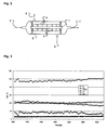
Proben des für gemischtleitende Membranen geeigneten Materials Ba(Co,Fe,Zr)O3-δ. welches nachstehend mit BCFZ bezeichnet wird (
Anschließend wurde mittels X-Ray Diffraction (XRD) die Kristallstruktur der Proben in Abhängigkeit von der Verweildauer bestimmt.
Zusätzlich zu dieser Zerstörung der Membran ist bei Anwesenheit von Luft auf einer Seite der Membran eine Ausbildung von unterschiedlichen Gitterkonstanten auf beiden Seiten der Membran mit der Folge mechanischer Belastungen in Folge chemisch induzierten Spannungen zu beobachten (
Es ist folglich sowohl auf experimenteller als auch auf theoretischer Basis zu befürchten, dass eine keramische Membran mit der Zusammensetzung BCFZ bei der Nutzung zur Herstellung von Synthesegas zerstört wird, so dass trotz der grundsätzlich geeigneten Materialeigenschaft bisher keine industrielle Nutzung möglich erschien.It is therefore to be feared on both an experimental and a theoretical basis that a ceramic membrane with the composition BCFZ is destroyed when used for the production of synthesis gas, so that despite the fundamentally suitable material property so far no industrial use appeared possible.
Weiterhin ist bei einer direkten Anlagerung von Katalysatormaterial an der Membran zu befürchten, dass bei der erforderlichen Temperatur von über 800°C chemische Feststoffreaktionen im Kontaktbereich der Oberflächen stattfinden, welche ebenfalls zur Schädigung oder lokalen Zerstörung der Membran führen können.Furthermore, it is to be feared in a direct addition of catalyst material to the membrane that take place at the required temperature of about 800 ° C chemical solid reactions in the contact region of the surfaces, which can also lead to damage or local destruction of the membrane.
Eine Möglichkeit zur Umgehung dieser Zerstörung wird in
Eine weitere Möglichkeit, die reduktive Zerstörung der Membran zu vermeiden, beschreibt die
Die
Aus dem Stand der Technik ergibt sich somit die Aufgabe, einen Oxidationsreaktor mit einer sauerstoffleitenden Membran zu entwickeln, wobei die Membran eine hohe Reduktionsstabilität und hohe mechanische Stabilität aufweist.The object of the prior art is therefore to develop an oxidation reactor with an oxygen-conducting membrane, the membrane having a high reduction stability and high mechanical stability.
Die vorliegende Erfindung löst diese Aufgabe durch einen Oxidationsreaktor gemäß dem Anspruch 1, der eine Zuleitung für ein sauerstoffhaltiges Gas, welche in einen Verteilerraum oder ein \/erteilerelement führt, umfasst. Weiterhin umfasst der Oxidationsreaktor eine Zuleitung für ein ganz oder teilweise zu oxidierendes Rohgas, welche in einen Reaktionsraum führt, wobei in dem Reaktionsraum eine Vielzahl von gasdichten sauerstoffleitenden Membranelementen angeordnet sind. Die vorliegende Erfindung löst die Aufgabe weiterhin durch einen Reaktor, in dem die Membranelemente in Form eines Bündels oder einer Gruppe parallel miteinander verwobener oder verwundener Membranelemente verwendbar sind.The present invention solves this object by an oxidation reactor according to
Die Membranelemente weisen bezogen auf den Sauerstofftransport eine Eintritts- und eine Austrittsfläche auf, wobei die Austrittsfläche als äußere Oberfläche definiert ist, die auf der Seite des Reaktionsraumes angeordnet ist. Die Membranelemente stellen die räumliche Verbindung von Verteilerraum und einem Sammelraum und/oder einem Auslass dar. Das sauerstoffhaltige Gas kann im Betrieb des Reaktors diesen in der Reihenfolge: Einlass, Verteilerraum, Membranelemente, Sammelraum und/oder Auslass durchströmen, wobei der Reaktionsraum mit Katalysator befüllbar ist.The membrane elements have an inlet and an outlet surface with respect to the oxygen transport, wherein the outlet surface is defined as an outer surface which is arranged on the side of the reaction space. The membrane elements represent the spatial connection of distributor space and a collecting space and / or an outlet. During operation of the reactor, the oxygen-containing gas can flow through these in the order: inlet, distribution space, membrane elements, collecting space and / or outlet, the reaction space being filled with catalyst is.
Dabei wird mittels eines oder mehrerer Distanzelemente ein definierter Mindestabstand zwischen der äußeren Oberfläche eines Verbundes von Membranelementen zum einfüllbaren Katalysator sichergestellt. Der Verbund kann dabei ein Bündel oder Gruppe paralleler oder miteinander verwobener oder verwundener Membranelemente sein.In this case, a defined minimum distance between the outer surface of a composite of membrane elements is ensured by means of one or more spacer elements to the fillable catalyst. The composite may be a bundle or group of parallel or interwoven or twisted membrane elements.
Vorteilhafterweise sind die Distanzelemente des erfindungsgemäßen Reaktors inerte Formkörper, welche die Membranelemente als Bündel oder Gruppe umhüllen oder zum Reaktionsraum hin vorgelagert sind. Die Formkörper können dabei als Schüttung vorliegen und/oder als Einzelelement, wie beispielsweise ein Mantelrohr, geformt sein. Das inerte Material weist dabei ein Porenvolumen oder eine Perforation auf, welche kleiner als der Feinkornanteil des einfüllbaren Katalysators ist.Advantageously, the spacer elements of the reactor according to the invention are inert shaped bodies which encase the membrane elements as a bundle or group or are upstream of the reaction space. The moldings may be present as a bed and / or be formed as a single element, such as a jacket tube. The inert material in this case has a pore volume or a perforation which is smaller than the fine grain content of the fillable catalyst.
Die Distanzelemente können in einer weiteren Ausführungsform aus ein oder mehreren inerten Materialien gebildet sein, welche direkt auf der äußeren Membranoberfläche anhaften. Distanzelemente einer derartigen Form würden durch eine geeignete Porenstruktur, welche kleiner als der Feinanteil der Katalysatorschüttung ist, den Katalysator vom direkten Kontakt mit den sauerstoffleitenden Membranelementen abhalten.In a further embodiment, the spacer elements can be formed from one or more inert materials which adhere directly to the outer membrane surface. Spacer elements of such a shape would prevent the catalyst from direct contact with the oxygen-conducting membrane elements by a suitable pore structure, which is smaller than the fines content of the catalyst bed.
Eine vergleichbare Rückhaltung kann erreicht werden, wenn die Distanzelemente katalytisch wirksame Formkörper sind, welche in denjenigen Bereichen bei bestimmungsgemäßem Betrieb des Reaktors oxidiert und dadurch inertisiert werden, welche der Austrittsfläche der Membran gegenüberliegend und/oder berührend angeordnet sind.A comparable retention can be achieved if the spacer elements are catalytically active moldings which are oxidized and thereby rendered inert in those areas during normal operation of the reactor which are arranged opposite and / or touching the outlet surface of the membrane.
Die Formgebung der Distanzelemente in dem erfindungsgemäßen Oxidationsreaktor ist dabei entweder regelmäßig oder weist eine unregelmäßige Struktur auf. Die Distanzelemente können weiterhin dadurch verbessert werden, dass diese eine oder mehrere katalytisch aktive Oberflächen aufweisen. Idealerweise sind die Distanzelemente derart geformt, dass die zum Reaktionsraum weisenden Oberflächen mit katalytisch aktivem Material beschichtet oder aus katalytisch aktivem Material gebildet sind.The shaping of the spacer elements in the oxidation reactor according to the invention is either regular or has an irregular structure. The spacer elements can be further improved by having one or more catalytically active surfaces. Ideally, the spacer elements are shaped such that the surfaces facing the reaction space are coated with catalytically active material or formed from catalytically active material.
In einer vorteilhaften Ausführungsform sind die Membranelemente der beiden vorgenannten Oxidationsreaktoren aus einem oder mehreren der Materialien gebildet, welche aus der Gruppe der Perowskite (ABO3), perowskitverwandten Strukturen, Fluoritstrukturen (AO2), Aurivilliusstrukturen ([Bi2O2][An-1BnOx]) oder der Brownmilleritstrukturen (A2B2O5) stammen. Besonders geeignet für den O2-Transport und somit die Nutzung in dem erfindungsgemäßen Oxidationsreaktor sind Membranelemente, die aus einem oder mehreren der Materialien gebildet ist, welche durch folgende allgemeine Strukturformeln beschrieben werden können: La1-x(Ca,Sr,Ba)xCo1-yFeyO3-δ, Ba(Sr)Co1-xFexO3-δ, Sr(Ba)Ti(Zr)1-x-yCoyFexO3-δ, BaCoxFeyZr1-x-yO3-δ, La1-xSrxGa1-yFeyO3-δ, La2NixFeyO4-δ, La0,5Sr0,5MnO3-δ, LaFe(Ni)O3-δ oder La0,9Sr0,1FeO3-δ.In an advantageous embodiment, the membrane elements of the two aforementioned oxidation reactors are formed from one or more of the materials selected from the group of perovskites (ABO 3 ), perovskite-related structures, fluorite structures (AO 2 ), Aurivillius structures ([Bi 2 O 2 ] [A n -1 B n O x ]) or the Brownmilleritstrukturen (A 2 B 2 O 5 ) come. Particularly suitable for O 2 transport and thus use in the oxidation reactor according to the invention are membrane elements which are formed from one or more of the materials which can be described by the following general structural formulas: La 1-x (Ca, Sr, Ba) x Co 1-y Fe y O 3 -δ , Ba (Sr) Co 1-x Fe x O 3-δ , Sr (Ba) Ti (Zr) 1-xy Co y Fe x O 3-δ , BaCo x Fe y Zr 1-xy O 3-δ , La 1-x Sr x Ga 1-y Fe y O 3 -δ , La 2 Ni x Fe y O 4-δ , La 0.5 Sr 0.5 MnO 3-δ , La Fe (Ni) O 3-δ or La 0.9 Sr 0.1 FeO 3-δ .
Idealerweise weisen die Membranelemente dabei eine Sauerstoffpermeanz auf, die bei 950°C und einer Sauerstoffpartialdruckdifferenz von >0,1 bar zwischen den sich auf den beiden Seiten der Membranelemente befindlichen freien Gasphasen im Mittel gleich oder größer als 0,1 Nm3/(m2h) ist.Ideally, the membrane elements in this case have an oxygen permeance, which at 950 ° C and a oxygen partial pressure difference of> 0.1 bar between the located on both sides of the membrane elements free gas phases on average equal to or greater than 0.1 Nm 3 / (m 2 h) is.
Von der Erfindung ist weiterhin ein Verfahren zur Oxidation von Stoffen umfasst, bei welchem ein Oxidationsreaktor nach einem der vorstehenden Ausführungsformen eingesetzt wird, dessen Reaktionsraum mit einem Katalysator gefüllt ist und
- Sauerstoff oder ein sauerstoffhaltiges Gas über den Einlass in den Verteilerraum des Oxidationsreaktors geleitet wird,
- in den Reaktionsraum ein zu oxidierendes Gas oder Gasgemisch geleitet wird,
- wobei die Temperatur im Reaktionsraum zwischen 200 - 1200°C, bevorzugt 500 - 1000°C und idealerweise 700 - 900°C beträgt und weiterhin
- der Druck zwischen 1 - 200 bar, bevorzugt 10 - 70 bar und idealerweise 30
bis 60 bar beträgt.
- Oxygen or an oxygen-containing gas is passed via the inlet into the distributor space of the oxidation reactor,
- a gas or gas mixture to be oxidized is passed into the reaction space,
- wherein the temperature in the reaction space between 200 - 1200 ° C, preferably 500 - 1000 ° C and ideally 700 - 900 ° C and further
- the pressure is between 1 and 200 bar, preferably between 10 and 70 bar, and ideally between 30 and 60 bar.
Eine vorteilhafte Ausführungsform des Oxidationsverfahrens sieht vor, dass das zu oxidierende Gas bevorzugt Methan oder Erdgas mit einem hohen Methananteil ist, welches auch nichtoxiderbare Bestandteile enthalten kann.An advantageous embodiment of the oxidation process provides that the gas to be oxidized is preferably methane or natural gas with a high methane content, which may also contain non-oxidisable constituents.
Weiterhin ist von der Erfindung auch die Verwendung des vorstehend genannten Oxidationsverfahrens in einer der Ausführungsformen für die Herstellung von Synthesegas mit den Hauptkomponenten H2 und CO umfasst. Auch von der Erfindung umfasst ist der Einsatz des erfindungsgemäßen Oxidationsverfahrens für die oxidative Dehydrierung von Alkanen, die oxidative Methankupplung, die partielle Oxidation höherer Kohlenwasserstoffe und/oder Kohlenwasserstoffderivate oder die selektive Oxidation einzelner Bestandteile von Gasgemischen,Furthermore, the invention also includes the use of the abovementioned oxidation process in one of the embodiments for the production of synthesis gas with the main components H 2 and CO. Also encompassed by the invention is the use of the oxidation process according to the invention for the oxidative dehydrogenation of alkanes, the oxidative methane coupling, the partial oxidation of higher hydrocarbons and / or hydrocarbon derivatives or the selective oxidation of individual constituents of gas mixtures,
Anhand des nachstehenden Beispiels werden die Vorteile des erfindungsgemäßen Oxidationsreaktors und des Verfahrens belagt.The advantages of the oxidation reactor according to the invention and the process are covered by the following example.
Zur Herstellung von Synthesegas wurde aus dem an und für sich unter den zu erwartenden Bedingungen thermodynamisch instabilen Material BCFZ Hohlfasern mit folgenden Abmessungen hergestellt (
- Länge 30 cm
- Außendurchmesser ca. 1,5 mm
Wandstärke etwa 200 µm
-
Length 30 cm - Outer diameter approx. 1.5 mm
- Wall thickness about 200 microns
Ein nachstehend näher beschriebener und in
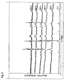
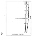
Der gesamte Reaktor wurde bei 850°C kontinuierlich über mehrere hundert Stunden betrieben. Während des Betriebes permeiert Sauerstoff von der Luftseite kommend durch die Membran und wurde auf der Permeatseite mit Methan zu Synthesegas umgesetzt. Ein beispielhaftes Diagramm für die Zusammensetzung des Produktgases zeigt
Nach Abschluss des Versuches wurde die Membran einer XRD-Analyse unterzogen, welche mit einer entsprechenden XRD-Analyse der fischen Membran verglichen wurde. Das in
Der Grund für diese unerwartete Stabilität könnte die Ausbildung einer Sauerstoff— Schutzschicht über der Membran im beschriebenen Reaktorsystem sein. Es wird vermutet, dass aufgrund des um die Membran angeordneten porösen Al2O3-Rohres, ein erhöhter Stofftransportwiderstand des Sauerstoffes von der permeatseitigen Membranoberfläche zum Katalysator aufgebaut wird. Es bildet sich somit ein lokales Maximum der Sauerstoffkonzentration direkt an der permeatseitigen Oberfläche der Membran, wodurch diese vor einer Zerstörung geschützt wird.The reason for this unexpected stability could be the formation of an oxygen protective layer over the membrane in the described reactor system. It is assumed that, due to the porous Al 2 O 3 tube arranged around the membrane, an increased mass transfer resistance of the oxygen from the permeate-side membrane surface to the catalyst is built up. Thus, a local maximum of the oxygen concentration forms directly on the permeate side surface of the membrane, thereby protecting it from destruction.
Durch die Variation von Dicke, Porenstruktur und Anordnung der Distanzelemente sowie der Strömungsbedingungen im Membranmodul und insbesondere im Reaktionsraum kann somit passend auf das jeweilige Membranmaterial ein geeigneter Reaktor entwickelt werden.By varying the thickness, pore structure and arrangement of the spacer elements and the flow conditions in the membrane module and in particular in the reaction space, a suitable reactor can thus be developed to suit the respective membrane material.
Durch den Einsatz von Distanzelementen zwischen äußerer Membranoberfläche und Katalysator kann somit das Ausmaß der Sauerstoff-Stofftransporthemmung auf der Permeatseite so eingestellt werden, dass eine lokale Sauerstoffschutzschicht der erwünschten Intensität über der Membranoberfläche gebildet wird. Entscheidend ist dabei der gezielte Abtransport des Sauerstoffes von der Permeatseite der Membran, damit die nachfolgende Umsetzung des Sauerstoffes am Katalysator gebremst wird. Dagegen nicht entscheidend ist der Stofftransport der reaktiven Medien, wie hier des Methans bzw. des Wasserstoffs, zur Membran hin, da der Schutz der Membran sich nicht durch eine geringe Konzentration der reaktiven Komponente an der permeatseitigen Oberfläche der Membran ergibt. Der Schutz ergibt sich vielmehr dadurch, dass ein hinreichend langsamer Abtransport des Sauerstoffes mit einer gleichzeitig hinreichend hohen Sauerstoffpermeation durch die Membran gekoppelt wird. In der Folge liegt an der permeatseitigen Membranoberfläche lokal eine signifikante Menge an freiem Sauerstoff vor.By using spacer elements between the outer membrane surface and the catalyst, the extent of oxygen mass transport inhibition on the permeate side can thus be adjusted so that a local oxygen protection layer of the desired intensity is formed over the membrane surface. Crucial here is the targeted removal of oxygen from the permeate side of the membrane, so that the subsequent conversion of the oxygen is braked on the catalyst. On the other hand, it is not crucial to transport the mass of the reactive media, such as methane or hydrogen, towards the membrane, since the protection of the membrane does not result from a low concentration of the reactive component on the permeate side surface of the membrane. The protection results rather from the fact that a sufficiently slow removal of the oxygen is coupled with a simultaneously sufficiently high oxygen permeation through the membrane. As a consequence, a significant amount of free oxygen is locally present at the permeate-side membrane surface.
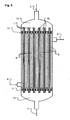
Strömungsführung der Luft 5 oder eines anderen O2-liefernden Mediums in die einzelnen durch Striche angedeuteten Membranmodule,- Abströmung der an O2 abgereicherten Luft 7 aus dem Bündel und
- gasdichten Barriere zwischen
den Gasströmen 5und 6.
- Flow of the
air 5 or another O 2 -derfernden medium into the individual indicated by dashes membrane modules, - Outflow of O 2 depleted air 7 from the bundle and
- gastight barrier between the
gas streams
Diese Verbindungselemente 10 können beispielsweise gebohrte Stahlplatten sein, in welche die einzelnen Membranmodule eingeklebt werden. Das Bündel aus Membranfasem kann wie in
Im Betrieb durchströmt der sauerstoffliefernde Strom 5 die Fasern und gibt einen Teil oder seinen gesamten enthaltenen Sauerstoff durch die Membranelemente in den Faserzwischenraum ab. Anschließend verlässt der bezüglich Sauerstoff abgereicherte Reststrom 7 das Faserbündel. Die Katalysatorschüttung 9 wird von dem zu oxidierenden Strom 6 durchströmt, wobei dieser durch Umsetzung mit dem durch die Membran 1 permeierten Sauerstoff sowie ggf. weiteren Reaktionen zum Produktstrom 8 umgesetzt wird. Die Erfindung ist dabei nicht auf die vorstehend genannten konstruktiven Beispiele beschränkt.In operation, the oxygen-providing
Die beschriebenen Beispiele stellen keine Einschränkung der Erfindung dar, da dem Fachmann eine ganze Reihe von Möglichkeiten bekannt sind, gezielt einen Stofftransportwiderstand zwischen zwei Teilen eines Reaktors konstruktiv und/oder durch Wahl der Betriebsbedingungen zu erzeugen.The examples described do not represent a limitation of the invention, since a number of possibilities are known to the person skilled in the art, specifically a mass transfer resistance between two parts of a reactor constructive and / or by selecting the operating conditions.
Der erfindungsgemäße Reaktor und das Verfahren sind weiterhin neben der Herstellung von Synthesegas mittels gemischtleitender Membranelemente auch auf weitere Oxidationsreaktionen anwendbar, bei welchen sauerstofftransportierende Membranelemente sinnvoll eingesetzt werden können. Beispiele für derartige Anwendungen sind die oxidative Dehydrierung von Alkanen, die oxidative Methankupplung, die partielle Oxidation höherer Kohlenwasserstoffe und/oder Kohlenwasserstoffderivate oder die selektive Oxidation einzelner Bestandteile von Gasgemischen.The reactor according to the invention and the process are furthermore applicable not only to the production of synthesis gas by means of mixed-conducting membrane elements but also to further oxidation reactions in which oxygen-transporting membrane elements can be usefully used. Examples of such applications are the oxidative dehydrogenation of alkanes, the oxidative methane coupling, the partial oxidation of higher hydrocarbons and / or hydrocarbon derivatives or the selective oxidation of individual constituents of gas mixtures.
Somit stehen dem Fachmann eine Vielzahl an bisher nicht für einsetzbar gehaltenen Membranmaterialien für industrielle Reaktoren und/oder Verfahren zur Verfügung, welche bisher aufgrund ihrer thermodynamischen und mechanischen Instabilität und sehr geringen Standzeiten nicht verwendet werden konnten.Thus, the skilled person a variety of previously held for use membrane materials for industrial reactors and / or methods are available, which previously could not be used due to their thermodynamic and mechanical instability and very short lives.
Claims (13)
- Oxidation reactor encompassing
a feed line for an oxygenous gas (5), which communicates with a distribution chamber (12) or a distribution element, a feed line intended for a raw gas (6) to be partly or completely oxidised and communicating with a reaction chamber (2),
a multitude of gas-tight and oxygen-conductive membrane elements (1) being arranged in the reaction chamber (2), the external surfaces of said elements forming inlet and outlet surfaces - referred to the gas transport -, the outlet surfaces being provided on the side of the reaction chamber (2), and these membrane elements (1) constituting a connection between the distribution chamber (2) and a collecting chamber (13) and/or discharge section (6), the said parts allowing passage of the oxygenous gas (6),
characterised in that
the reaction chamber (2) contains a bulk catalyst material (9), and
one or several spacer elements establish a defined minimum distance between the external surface of the membrane elements (1) and the catalyst packing (9) and a multitude of the membrane elements (1) are arranged in the form of a block, the said block consisting of a bundle or a group of parallel or intertwisted or intertwined membrane elements (1), and the spacer elements establish a defined minimum distance between the external surfaces of a bundle or a group of the membrane elements (1) of the block and the catalyst packing (9). - Oxidation reactor according to Claim 1,
characterised in that
the spacer elements are inert components which enclose the membrane elements as bundle or group of the block and are arranged in the direction towards the reaction chamber (2), the said components being of bulk type or being formed as individual element. - Oxidation reactor according to any of the preceding Claims 1 or 2,
characterised in that
the spacer elements are inert components which enclose the membrane elements (1) as bundle or group of the block and are arranged in the direction towards the reaction chamber (2), the said inert component(s) being formed as individual element and said individual element as jacket pipe. - Oxidation reactor according to any of the preceding Claims 1 to 3,
characterised in that
the spacer elements consist of an inert material which is directly applied to the external surface of the membrane. - Oxidation reactor according to any of the preceding Claims 2 to 4,
characterised in that
the inert material has a pore volume that is smaller than the fines content of the catalyst packing (9) of a bulk catalyst material. - Oxidation reactor according to any of the preceding Claims 1 to 5,
characterised in that
the spacer elements are of a regular or irregular structure. - Oxidation reactor according to Claim 6,
characterised in that
the membrane elements (1) consist of one or several materials from the group of Perovskite (ABO3), Perovskite-related structures, fluorite structures (AO2), Aurivillius structures ([Bi2O2][An-1BnOx]) or Brownmillerite structures (A2B2O5). - Oxidation reactor according to Claims 1 to 7,
characterised in that
the membrane elements (1) consist of one or several materials which can be described by the general structural formulae listed below:La1-x(Ca,Sr,Ba),Co1-yFeyO3-δ, Ba(Sr)Co1-xFexO3-δ, Sr(Ba)Ti (Zr)1-x-yCoyFexO3-δ, BaCoxFeyZr1-x-yO3-δ, La1-xSrxGa1-yFeyO3-δ La0,5Sr0,5MnO3-δ, La2NixFeyO4-δ, LaFe(Ni)O3-δ or La0,9Sr0,1FeO3-δ. - Oxidation reactor according to Claims 1 to 8
characterised in that
the membrane elements (1) exhibit an oxygen permeability which has an average value of ≥ 0.1 Nm3(m2h) at 950°C and an oxygen partial pressure difference of >0.1 bar between free gas phases located on the two sides of the membrane (1). - Process for the oxidation of fluids,
characterised in that
a reactor is used according to one of the aforementioned claims, the reaction chamber (2) of which being filled with a catalyst (9) and- oxygen or an oxygenous gas being fed into the distribution chamber of the oxidation reactor via the inlet,- a gas or gas mixture to be oxidised being piped into the reaction chamber.- with the temperature in the reaction chamber ranging from 200 to 1200°C, preferably from 500 to 1000°C and ideally from 700 to 900°C and the pressure ranging between 1 and 200 bars, preferably between 10 and 70 bars and ideally between 30 and 60 bars. - Process for the oxidation of fluids according to Claim 10,
characterised in that
the gas to be oxidised (6) also contains non-oxidisable constituents and is preferably methane or natural gas with a high content of methane. - Utilisation of the process according to any of the preceding Claims 10 or 11,
characterised in that
synthesis gas with the main components H2 and CO is produced by this process. - Utilisation of the process according to any of the preceding Claims 10 to 12,
characterised in that
this process is used to perform oxidative dehydrogenation of alkanes, oxidative coupling of methane, partial oxidation of higher hydrocarbons and/or hydrocarbon derivatives or selective oxidation of individual constituents of gas mixtures
Applications Claiming Priority (2)
| Application Number | Priority Date | Filing Date | Title |
|---|---|---|---|
| DE102005060171A DE102005060171A1 (en) | 2005-12-14 | 2005-12-14 | Oxidation reactor and oxidation process |
| PCT/EP2006/011629 WO2007068369A1 (en) | 2005-12-14 | 2006-12-05 | Oxidation reactor and oxidation process |
Publications (2)
| Publication Number | Publication Date |
|---|---|
| EP1968738A1 EP1968738A1 (en) | 2008-09-17 |
| EP1968738B1 true EP1968738B1 (en) | 2012-10-31 |
Family
ID=37907494
Family Applications (1)
| Application Number | Title | Priority Date | Filing Date |
|---|---|---|---|
| EP06829277A Not-in-force EP1968738B1 (en) | 2005-12-14 | 2006-12-05 | Oxidation reactor and oxidation process |
Country Status (13)
| Country | Link |
|---|---|
| US (1) | US20090018373A1 (en) |
| EP (1) | EP1968738B1 (en) |
| JP (1) | JP5366556B2 (en) |
| KR (1) | KR101376082B1 (en) |
| CN (1) | CN101394924B (en) |
| CA (1) | CA2634263A1 (en) |
| DE (1) | DE102005060171A1 (en) |
| DK (1) | DK1968738T3 (en) |
| EA (1) | EA200870037A1 (en) |
| EG (1) | EG26485A (en) |
| ES (1) | ES2397966T3 (en) |
| WO (1) | WO2007068369A1 (en) |
| ZA (1) | ZA200805086B (en) |
Families Citing this family (25)
| Publication number | Priority date | Publication date | Assignee | Title |
|---|---|---|---|---|
| US7666449B2 (en) * | 2001-06-20 | 2010-02-23 | Metaproteomics, Llc | Anti-inflammatory pharmaceutical compositions for reducing inflammation and the treatment or prevention of gastric toxicity |
| WO2009071463A2 (en) * | 2007-12-03 | 2009-06-11 | Basf Se | Oxidative methane coupling via membrane reactor |
| DE102008013292A1 (en) | 2008-03-07 | 2009-09-10 | Borsig Process Heat Exchanger Gmbh | Process for regenerating oxygen-conducting ceramic membranes and reactor |
| DE102009039920A1 (en) | 2009-09-03 | 2011-03-10 | Karl-Heinz Tetzlaff | Method and apparatus for using oxygen in the steam reforming of biomass |
| DE102009060489A1 (en) | 2009-12-29 | 2011-06-30 | Uhde GmbH, 44141 | Apparatus and method for controlling the oxygen permeation through non-porous oxygen anions conductive ceramic membranes and their use |
| JP2012091984A (en) * | 2010-10-28 | 2012-05-17 | Mitsubishi Heavy Ind Ltd | High temperature seal material, high temperature seal body and oxygen permeation module containing the high temperature seal body |
| NL2006245C2 (en) * | 2011-02-18 | 2012-08-21 | Stichting Energie | MEMBRANE REACTOR AND PROCESS FOR THE PRODUCTION OF A GASEOUS PRODUCT WITH SUCH REACTOR. |
| US9555209B2 (en) | 2011-04-13 | 2017-01-31 | Michael Klein | Gas delivery method and apparatus |
| CN103130748B (en) * | 2011-11-29 | 2015-04-29 | 岳阳昌德化工实业有限公司 | Cyclohexene oxidizing method |
| EP2607301A1 (en) * | 2011-12-20 | 2013-06-26 | Karl-Heinz Tetzlaff | Method and device for reforming natural gas |
| JP2016505501A (en) | 2012-12-19 | 2016-02-25 | プラクスエア・テクノロジー・インコーポレイテッド | Method for sealing an oxygen transport membrane assembly |
| WO2014107707A2 (en) * | 2013-01-07 | 2014-07-10 | Praxair Technology, Inc. | High emissivity and high temperature diffusion barrier coatings for an oxygen transport membrane assembly |
| US9296671B2 (en) | 2013-04-26 | 2016-03-29 | Praxair Technology, Inc. | Method and system for producing methanol using an integrated oxygen transport membrane based reforming system |
| US9938145B2 (en) | 2013-04-26 | 2018-04-10 | Praxair Technology, Inc. | Method and system for adjusting synthesis gas module in an oxygen transport membrane based reforming system |
| US9611144B2 (en) | 2013-04-26 | 2017-04-04 | Praxair Technology, Inc. | Method and system for producing a synthesis gas in an oxygen transport membrane based reforming system that is free of metal dusting corrosion |
| US9212113B2 (en) | 2013-04-26 | 2015-12-15 | Praxair Technology, Inc. | Method and system for producing a synthesis gas using an oxygen transport membrane based reforming system with secondary reforming and auxiliary heat source |
| EP3055052A2 (en) | 2013-10-07 | 2016-08-17 | Praxair Technology Inc. | Ceramic oxygen transport membrane array reactor and reforming method |
| US10822234B2 (en) | 2014-04-16 | 2020-11-03 | Praxair Technology, Inc. | Method and system for oxygen transport membrane enhanced integrated gasifier combined cycle (IGCC) |
| WO2016057164A1 (en) | 2014-10-07 | 2016-04-14 | Praxair Technology, Inc | Composite oxygen ion transport membrane |
| US10441922B2 (en) | 2015-06-29 | 2019-10-15 | Praxair Technology, Inc. | Dual function composite oxygen transport membrane |
| US10118823B2 (en) | 2015-12-15 | 2018-11-06 | Praxair Technology, Inc. | Method of thermally-stabilizing an oxygen transport membrane-based reforming system |
| US9938146B2 (en) | 2015-12-28 | 2018-04-10 | Praxair Technology, Inc. | High aspect ratio catalytic reactor and catalyst inserts therefor |
| JP2019513081A (en) | 2016-04-01 | 2019-05-23 | プラクスエア・テクノロジー・インコーポレイテッド | Catalyst-containing oxygen transport membrane |
| JP6845102B2 (en) * | 2017-06-30 | 2021-03-17 | 日本特殊陶業株式会社 | Reform structure and reformer |
| EP3797085A1 (en) | 2018-05-21 | 2021-03-31 | Praxair Technology, Inc. | Otm syngas panel with gas heated reformer |
Family Cites Families (20)
| Publication number | Priority date | Publication date | Assignee | Title |
|---|---|---|---|---|
| CA2081170C (en) * | 1992-10-22 | 2002-12-24 | Alaa-Eldin Moustafa Adris | Fluidized bed reaction system for steam/hydrocarbon gas reforming to produce hydrogen |
| AU706663B2 (en) * | 1994-09-23 | 1999-06-17 | Standard Oil Company, The | Oxygen permeable mixed conductor membranes |
| US5573737A (en) | 1994-09-27 | 1996-11-12 | The United States Of America As Represented By The United States Department Of Energy | Functionally gradient material for membrane reactors to convert methane gas into value-added products |
| US5681373A (en) * | 1995-03-13 | 1997-10-28 | Air Products And Chemicals, Inc. | Planar solid-state membrane module |
| BR9601078A (en) * | 1995-05-18 | 1998-01-06 | Praxair Technology Inc | Process for removing oxygen from a feed stream to obtain an oxygen-depleted product stream |
| US5820655A (en) * | 1997-04-29 | 1998-10-13 | Praxair Technology, Inc. | Solid Electrolyte ionic conductor reactor design |
| US6077323A (en) * | 1997-06-06 | 2000-06-20 | Air Products And Chemicals, Inc. | Synthesis gas production by ion transport membranes |
| US6106591A (en) * | 1997-06-23 | 2000-08-22 | Praxair Technology, Inc. | Process for reducing carbon production in solid electrolyte ionic conductor systems |
| US6200541B1 (en) * | 1997-10-28 | 2001-03-13 | Bp Amoco Corporation | Composite materials for membrane reactors |
| US5935533A (en) * | 1997-10-28 | 1999-08-10 | Bp Amoco Corporation | Membrane reactor hollow tube module with ceramic/metal interfacial zone |
| US6139810A (en) * | 1998-06-03 | 2000-10-31 | Praxair Technology, Inc. | Tube and shell reactor with oxygen selective ion transport ceramic reaction tubes |
| EP1035072B1 (en) * | 1999-03-05 | 2004-05-12 | Haldor Topsoe A/S | Process for autothermal catalytic stream reforming |
| JP2001097789A (en) * | 1999-10-01 | 2001-04-10 | Nippon Steel Corp | Ceramic composite material |
| JP2002085946A (en) * | 2000-09-20 | 2002-03-26 | Teikoku Oil Co Ltd | Ceramic membrane-type reactor and method of producing hydrogen at low pressure using the same |
| US6695983B2 (en) * | 2001-04-24 | 2004-02-24 | Praxair Technology, Inc. | Syngas production method utilizing an oxygen transport membrane |
| US20030039601A1 (en) * | 2001-08-10 | 2003-02-27 | Halvorson Thomas Gilbert | Oxygen ion transport membrane apparatus and process for use in syngas production |
| JP3914416B2 (en) * | 2001-11-06 | 2007-05-16 | 帝国石油株式会社 | Membrane reactor |
| JP2003346859A (en) * | 2002-05-23 | 2003-12-05 | Nissan Motor Co Ltd | Carbon monoxide removal device |
| US7125528B2 (en) * | 2002-05-24 | 2006-10-24 | Bp Corporation North America Inc. | Membrane systems containing an oxygen transport membrane and catalyst |
| FR2859115B1 (en) * | 2003-08-28 | 2005-10-28 | Centre Nat Rech Scient | ELECTRONIC CONDUCTION MEMBRANES AND OXYGEN ION COMPRISING A MIXED OXIDE LAYER OF VANADIUM AND MAGNESIUM |
-
2005
- 2005-12-14 DE DE102005060171A patent/DE102005060171A1/en not_active Withdrawn
-
2006
- 2006-12-05 CA CA002634263A patent/CA2634263A1/en not_active Abandoned
- 2006-12-05 KR KR1020087016552A patent/KR101376082B1/en not_active IP Right Cessation
- 2006-12-05 JP JP2008544812A patent/JP5366556B2/en not_active Expired - Fee Related
- 2006-12-05 CN CN2006800528590A patent/CN101394924B/en not_active Expired - Fee Related
- 2006-12-05 DK DK06829277.0T patent/DK1968738T3/en active
- 2006-12-05 EP EP06829277A patent/EP1968738B1/en not_active Not-in-force
- 2006-12-05 ES ES06829277T patent/ES2397966T3/en active Active
- 2006-12-05 US US12/097,020 patent/US20090018373A1/en not_active Abandoned
- 2006-12-05 EA EA200870037A patent/EA200870037A1/en unknown
- 2006-12-05 WO PCT/EP2006/011629 patent/WO2007068369A1/en active Application Filing
-
2008
- 2008-06-11 EG EG2008060972A patent/EG26485A/en active
- 2008-06-11 ZA ZA200805086A patent/ZA200805086B/en unknown
Also Published As
| Publication number | Publication date |
|---|---|
| JP5366556B2 (en) | 2013-12-11 |
| ZA200805086B (en) | 2009-03-25 |
| DK1968738T3 (en) | 2013-01-28 |
| EA200870037A1 (en) | 2009-12-30 |
| EP1968738A1 (en) | 2008-09-17 |
| CN101394924A (en) | 2009-03-25 |
| KR101376082B1 (en) | 2014-03-19 |
| WO2007068369A1 (en) | 2007-06-21 |
| EG26485A (en) | 2013-12-10 |
| US20090018373A1 (en) | 2009-01-15 |
| ES2397966T3 (en) | 2013-03-12 |
| DE102005060171A1 (en) | 2007-06-21 |
| CN101394924B (en) | 2012-07-04 |
| CA2634263A1 (en) | 2007-06-21 |
| KR20080077667A (en) | 2008-08-25 |
| JP2009519195A (en) | 2009-05-14 |
Similar Documents
| Publication | Publication Date | Title |
|---|---|---|
| EP1968738B1 (en) | Oxidation reactor and oxidation process | |
| DE60103911T3 (en) | COMPOSITE CONDUCTIVE MEMBRANES FOR SYNTHESEGAS PRODUCTION | |
| DE102005006571A1 (en) | Process for oxygen enrichment in gases, suitable plants and their use | |
| DE69928707T2 (en) | Device for fluid separation with a mixture-conducting membrane of Mehrkomponentmetalloxiden | |
| DE69801053T3 (en) | AUTOTHERMIC REACTOR WITH A OXYGEN-LIQUID SEALING CERAMIC MEMBRANE AND USE THEREOF IN A SYNTHESEGAS GENERATING METHOD | |
| DE69824620T2 (en) | CATALYTIC MEMBRANE REACTOR WITH A THREE-DIMENSIONAL CATALYST IN THE OXIDATION ZONE | |
| DE69619003T3 (en) | Tubular monolithic membrane module | |
| DE102009039149A1 (en) | Catalytic membrane material coating | |
| DE60020772T2 (en) | Hydrogen permeability through proton- and electron-conducting mixed materials | |
| EP2417084B1 (en) | Method for reacting natural gas to aromatics while electrochemically removing hydrogen and while generating electric power and producing hydrogen | |
| WO2009071463A2 (en) | Oxidative methane coupling via membrane reactor | |
| EP2417059A1 (en) | Method for reacting natural gas to aromatics while electrochemically removing hydrogen | |
| DE19804286A1 (en) | Reactor for a catalytic chemical reaction, in particular a methanol reforming reactor | |
| DE69819210T2 (en) | MEMBRANE AND ITS APPLICATION | |
| DE19539648C2 (en) | Reactor for selective CO oxidation in H¶2¶-rich gas | |
| DE2910743A1 (en) | PROCESS FOR PRODUCING SYNTHESIS GAS MIXTURES WITH THE AID OF SEMIPERMEABLES HOLLOW FIBER MEMBRANES | |
| DE60211275T2 (en) | Sulfur control in ion-conducting membrane plants | |
| EP2595729B1 (en) | C02-tolerant conducting mixed oxide and its use for hydrogen separation | |
| DE69600851T3 (en) | Novel compositions having the ability to function under high carbon dioxide partial pressures for use in solid state devices for the production of oxygen | |
| EP2621855B1 (en) | Process for working up an exhaust gas from a system for producing hydroxylamine or hydroxylammonium salts | |
| DE102009060489A1 (en) | Apparatus and method for controlling the oxygen permeation through non-porous oxygen anions conductive ceramic membranes and their use | |
| DE19826496B4 (en) | Oxygen ion and electron-conducting ceramic membrane, process for their preparation and their use | |
| DE102009038814A1 (en) | Process for potting ceramic capillary membranes | |
| WO1999054948A1 (en) | Method and system for removing carbon monoxide from a reformate gas stream containing hydrogen | |
| WO2009109294A1 (en) | Method for regenerating oxygen-conducting ceramic membranes and reactor |
Legal Events
| Date | Code | Title | Description |
|---|---|---|---|
| PUAI | Public reference made under article 153(3) epc to a published international application that has entered the european phase |
Free format text: ORIGINAL CODE: 0009012 |
|
| 17P | Request for examination filed |
Effective date: 20080612 |
|
| AK | Designated contracting states |
Kind code of ref document: A1 Designated state(s): AT BE BG CH CY CZ DE DK EE ES FI FR GB GR HU IE IS IT LI LT LU LV MC NL PL PT RO SE SI SK TR |
|
| 17Q | First examination report despatched |
Effective date: 20081030 |
|
| RAP1 | Party data changed (applicant data changed or rights of an application transferred) |
Owner name: THYSSENKRUPP UHDE GMBH Owner name: BORSIG PROCESS HEAT EXCHANGER GMBH |
|
| GRAP | Despatch of communication of intention to grant a patent |
Free format text: ORIGINAL CODE: EPIDOSNIGR1 |
|
| DAX | Request for extension of the european patent (deleted) | ||
| GRAS | Grant fee paid |
Free format text: ORIGINAL CODE: EPIDOSNIGR3 |
|
| GRAA | (expected) grant |
Free format text: ORIGINAL CODE: 0009210 |
|
| AK | Designated contracting states |
Kind code of ref document: B1 Designated state(s): AT BE BG CH CY CZ DE DK EE ES FI FR GB GR HU IE IS IT LI LT LU LV MC NL PL PT RO SE SI SK TR |
|
| REG | Reference to a national code |
Ref country code: GB Ref legal event code: FG4D Free format text: NOT ENGLISH Ref country code: CH Ref legal event code: EP |
|
| REG | Reference to a national code |
Ref country code: AT Ref legal event code: REF Ref document number: 581678 Country of ref document: AT Kind code of ref document: T Effective date: 20121115 |
|
| REG | Reference to a national code |
Ref country code: IE Ref legal event code: FG4D Free format text: LANGUAGE OF EP DOCUMENT: GERMAN |
|
| REG | Reference to a national code |
Ref country code: DE Ref legal event code: R096 Ref document number: 502006012173 Country of ref document: DE Effective date: 20121227 |
|
| REG | Reference to a national code |
Ref country code: DK Ref legal event code: T3 |
|
| REG | Reference to a national code |
Ref country code: NL Ref legal event code: T3 |
|
| REG | Reference to a national code |
Ref country code: ES Ref legal event code: FG2A Ref document number: 2397966 Country of ref document: ES Kind code of ref document: T3 Effective date: 20130312 |
|
| REG | Reference to a national code |
Ref country code: LT Ref legal event code: MG4D |
|
| PG25 | Lapsed in a contracting state [announced via postgrant information from national office to epo] |
Ref country code: FI Free format text: LAPSE BECAUSE OF FAILURE TO SUBMIT A TRANSLATION OF THE DESCRIPTION OR TO PAY THE FEE WITHIN THE PRESCRIBED TIME-LIMIT Effective date: 20121031 Ref country code: LT Free format text: LAPSE BECAUSE OF FAILURE TO SUBMIT A TRANSLATION OF THE DESCRIPTION OR TO PAY THE FEE WITHIN THE PRESCRIBED TIME-LIMIT Effective date: 20121031 Ref country code: IS Free format text: LAPSE BECAUSE OF FAILURE TO SUBMIT A TRANSLATION OF THE DESCRIPTION OR TO PAY THE FEE WITHIN THE PRESCRIBED TIME-LIMIT Effective date: 20130228 Ref country code: SE Free format text: LAPSE BECAUSE OF FAILURE TO SUBMIT A TRANSLATION OF THE DESCRIPTION OR TO PAY THE FEE WITHIN THE PRESCRIBED TIME-LIMIT Effective date: 20121031 |
|
| PG25 | Lapsed in a contracting state [announced via postgrant information from national office to epo] |
Ref country code: PL Free format text: LAPSE BECAUSE OF FAILURE TO SUBMIT A TRANSLATION OF THE DESCRIPTION OR TO PAY THE FEE WITHIN THE PRESCRIBED TIME-LIMIT Effective date: 20121031 Ref country code: LV Free format text: LAPSE BECAUSE OF FAILURE TO SUBMIT A TRANSLATION OF THE DESCRIPTION OR TO PAY THE FEE WITHIN THE PRESCRIBED TIME-LIMIT Effective date: 20121031 Ref country code: SI Free format text: LAPSE BECAUSE OF FAILURE TO SUBMIT A TRANSLATION OF THE DESCRIPTION OR TO PAY THE FEE WITHIN THE PRESCRIBED TIME-LIMIT Effective date: 20121031 Ref country code: PT Free format text: LAPSE BECAUSE OF FAILURE TO SUBMIT A TRANSLATION OF THE DESCRIPTION OR TO PAY THE FEE WITHIN THE PRESCRIBED TIME-LIMIT Effective date: 20130228 Ref country code: CY Free format text: LAPSE BECAUSE OF FAILURE TO SUBMIT A TRANSLATION OF THE DESCRIPTION OR TO PAY THE FEE WITHIN THE PRESCRIBED TIME-LIMIT Effective date: 20121031 Ref country code: GR Free format text: LAPSE BECAUSE OF FAILURE TO SUBMIT A TRANSLATION OF THE DESCRIPTION OR TO PAY THE FEE WITHIN THE PRESCRIBED TIME-LIMIT Effective date: 20130201 |
|
| BERE | Be: lapsed |
Owner name: THYSSENKRUPP UHDE G.M.B.H. Effective date: 20121231 Owner name: BORSIG PROCESS HEAT EXCHANGER G.M.B.H. Effective date: 20121231 |
|
| PG25 | Lapsed in a contracting state [announced via postgrant information from national office to epo] |
Ref country code: SK Free format text: LAPSE BECAUSE OF FAILURE TO SUBMIT A TRANSLATION OF THE DESCRIPTION OR TO PAY THE FEE WITHIN THE PRESCRIBED TIME-LIMIT Effective date: 20121031 Ref country code: EE Free format text: LAPSE BECAUSE OF FAILURE TO SUBMIT A TRANSLATION OF THE DESCRIPTION OR TO PAY THE FEE WITHIN THE PRESCRIBED TIME-LIMIT Effective date: 20121031 Ref country code: MC Free format text: LAPSE BECAUSE OF NON-PAYMENT OF DUE FEES Effective date: 20121231 Ref country code: CZ Free format text: LAPSE BECAUSE OF FAILURE TO SUBMIT A TRANSLATION OF THE DESCRIPTION OR TO PAY THE FEE WITHIN THE PRESCRIBED TIME-LIMIT Effective date: 20121031 Ref country code: BG Free format text: LAPSE BECAUSE OF FAILURE TO SUBMIT A TRANSLATION OF THE DESCRIPTION OR TO PAY THE FEE WITHIN THE PRESCRIBED TIME-LIMIT Effective date: 20130131 |
|
| REG | Reference to a national code |
Ref country code: CH Ref legal event code: PL |
|
| PG25 | Lapsed in a contracting state [announced via postgrant information from national office to epo] |
Ref country code: RO Free format text: LAPSE BECAUSE OF FAILURE TO SUBMIT A TRANSLATION OF THE DESCRIPTION OR TO PAY THE FEE WITHIN THE PRESCRIBED TIME-LIMIT Effective date: 20121031 |
|
| PLBE | No opposition filed within time limit |
Free format text: ORIGINAL CODE: 0009261 |
|
| STAA | Information on the status of an ep patent application or granted ep patent |
Free format text: STATUS: NO OPPOSITION FILED WITHIN TIME LIMIT |
|
| REG | Reference to a national code |
Ref country code: IE Ref legal event code: MM4A |
|
| PG25 | Lapsed in a contracting state [announced via postgrant information from national office to epo] |
Ref country code: BE Free format text: LAPSE BECAUSE OF NON-PAYMENT OF DUE FEES Effective date: 20121231 |
|
| 26N | No opposition filed |
Effective date: 20130801 |
|
| PG25 | Lapsed in a contracting state [announced via postgrant information from national office to epo] |
Ref country code: IE Free format text: LAPSE BECAUSE OF NON-PAYMENT OF DUE FEES Effective date: 20121205 Ref country code: LI Free format text: LAPSE BECAUSE OF NON-PAYMENT OF DUE FEES Effective date: 20121231 Ref country code: CH Free format text: LAPSE BECAUSE OF NON-PAYMENT OF DUE FEES Effective date: 20121231 |
|
| REG | Reference to a national code |
Ref country code: DE Ref legal event code: R097 Ref document number: 502006012173 Country of ref document: DE Effective date: 20130801 |
|
| REG | Reference to a national code |
Ref country code: AT Ref legal event code: MM01 Ref document number: 581678 Country of ref document: AT Kind code of ref document: T Effective date: 20121205 |
|
| PG25 | Lapsed in a contracting state [announced via postgrant information from national office to epo] |
Ref country code: TR Free format text: LAPSE BECAUSE OF FAILURE TO SUBMIT A TRANSLATION OF THE DESCRIPTION OR TO PAY THE FEE WITHIN THE PRESCRIBED TIME-LIMIT Effective date: 20121031 |
|
| PG25 | Lapsed in a contracting state [announced via postgrant information from national office to epo] |
Ref country code: LU Free format text: LAPSE BECAUSE OF NON-PAYMENT OF DUE FEES Effective date: 20121205 Ref country code: AT Free format text: LAPSE BECAUSE OF NON-PAYMENT OF DUE FEES Effective date: 20121205 |
|
| PG25 | Lapsed in a contracting state [announced via postgrant information from national office to epo] |
Ref country code: HU Free format text: LAPSE BECAUSE OF FAILURE TO SUBMIT A TRANSLATION OF THE DESCRIPTION OR TO PAY THE FEE WITHIN THE PRESCRIBED TIME-LIMIT Effective date: 20061205 |
|
| PGFP | Annual fee paid to national office [announced via postgrant information from national office to epo] |
Ref country code: ES Payment date: 20141226 Year of fee payment: 9 Ref country code: DE Payment date: 20141211 Year of fee payment: 9 Ref country code: GB Payment date: 20141219 Year of fee payment: 9 Ref country code: DK Payment date: 20141219 Year of fee payment: 9 |
|
| PGFP | Annual fee paid to national office [announced via postgrant information from national office to epo] |
Ref country code: FR Payment date: 20141219 Year of fee payment: 9 Ref country code: NL Payment date: 20141219 Year of fee payment: 9 |
|
| PGFP | Annual fee paid to national office [announced via postgrant information from national office to epo] |
Ref country code: IT Payment date: 20141219 Year of fee payment: 9 |
|
| REG | Reference to a national code |
Ref country code: DE Ref legal event code: R119 Ref document number: 502006012173 Country of ref document: DE |
|
| REG | Reference to a national code |
Ref country code: DK Ref legal event code: EBP Effective date: 20151231 |
|
| GBPC | Gb: european patent ceased through non-payment of renewal fee |
Effective date: 20151205 |
|
| REG | Reference to a national code |
Ref country code: NL Ref legal event code: MM Effective date: 20160101 |
|
| REG | Reference to a national code |
Ref country code: FR Ref legal event code: ST Effective date: 20160831 |
|
| PG25 | Lapsed in a contracting state [announced via postgrant information from national office to epo] |
Ref country code: NL Free format text: LAPSE BECAUSE OF NON-PAYMENT OF DUE FEES Effective date: 20160101 Ref country code: DE Free format text: LAPSE BECAUSE OF NON-PAYMENT OF DUE FEES Effective date: 20160701 Ref country code: GB Free format text: LAPSE BECAUSE OF NON-PAYMENT OF DUE FEES Effective date: 20151205 |
|
| PG25 | Lapsed in a contracting state [announced via postgrant information from national office to epo] |
Ref country code: FR Free format text: LAPSE BECAUSE OF NON-PAYMENT OF DUE FEES Effective date: 20151231 |
|
| PG25 | Lapsed in a contracting state [announced via postgrant information from national office to epo] |
Ref country code: IT Free format text: LAPSE BECAUSE OF NON-PAYMENT OF DUE FEES Effective date: 20151205 |
|
| PG25 | Lapsed in a contracting state [announced via postgrant information from national office to epo] |
Ref country code: DK Free format text: LAPSE BECAUSE OF NON-PAYMENT OF DUE FEES Effective date: 20151231 |
|
| PG25 | Lapsed in a contracting state [announced via postgrant information from national office to epo] |
Ref country code: ES Free format text: LAPSE BECAUSE OF NON-PAYMENT OF DUE FEES Effective date: 20151206 |
|
| REG | Reference to a national code |
Ref country code: ES Ref legal event code: FD2A Effective date: 20180703 |