EP1968088A2 - Multipolar electrical switch equipped with an operating mechanism and switching modules - Google Patents
Multipolar electrical switch equipped with an operating mechanism and switching modules Download PDFInfo
- Publication number
- EP1968088A2 EP1968088A2 EP08011061A EP08011061A EP1968088A2 EP 1968088 A2 EP1968088 A2 EP 1968088A2 EP 08011061 A EP08011061 A EP 08011061A EP 08011061 A EP08011061 A EP 08011061A EP 1968088 A2 EP1968088 A2 EP 1968088A2
- Authority
- EP
- European Patent Office
- Prior art keywords
- axis
- frame
- modules
- partition
- connecting rod
- Prior art date
- Legal status (The legal status is an assumption and is not a legal conclusion. Google has not performed a legal analysis and makes no representation as to the accuracy of the status listed.)
- Granted
Links
Images

Classifications
-
- H—ELECTRICITY
- H01—ELECTRIC ELEMENTS
- H01H—ELECTRIC SWITCHES; RELAYS; SELECTORS; EMERGENCY PROTECTIVE DEVICES
- H01H33/00—High-tension or heavy-current switches with arc-extinguishing or arc-preventing means
- H01H33/60—Switches wherein the means for extinguishing or preventing the arc do not include separate means for obtaining or increasing flow of arc-extinguishing fluid
- H01H33/66—Vacuum switches
- H01H33/666—Operating arrangements
- H01H2033/6665—Details concerning the mounting or supporting of the individual vacuum bottles
-
- H—ELECTRICITY
- H01—ELECTRIC ELEMENTS
- H01H—ELECTRIC SWITCHES; RELAYS; SELECTORS; EMERGENCY PROTECTIVE DEVICES
- H01H33/00—High-tension or heavy-current switches with arc-extinguishing or arc-preventing means
- H01H33/60—Switches wherein the means for extinguishing or preventing the arc do not include separate means for obtaining or increasing flow of arc-extinguishing fluid
- H01H33/66—Vacuum switches
- H01H33/666—Operating arrangements
- H01H2033/6667—Details concerning lever type driving rod arrangements
-
- H—ELECTRICITY
- H01—ELECTRIC ELEMENTS
- H01H—ELECTRIC SWITCHES; RELAYS; SELECTORS; EMERGENCY PROTECTIVE DEVICES
- H01H33/00—High-tension or heavy-current switches with arc-extinguishing or arc-preventing means
- H01H33/02—Details
- H01H33/022—Details particular to three-phase circuit breakers
Definitions
- the invention relates to an electrical switchgear device multipole, and in particular to a multipole breaking apparatus comprising vacuum ampoules.
- the document EP 0 346 603 discloses a three-pole switchgear with three identical polar break modules arranged side by side on a chassis. Each module comprises a vacuum bulb provided with a movable control rod in translation.
- a spring drive mechanism of known type having a pole shaft allows the driving of the control rods of the three vacuum bulbs.
- Each control rod is connected to the pole shaft via an independent linkage, specific to the corresponding cut-off module.
- This linkage consists of a transmission lever, arranged between two connecting rods, one of the connecting rods connecting the lever to a crank of the pole shaft and the other connecting the lever to the control rod of the bulb to empty.
- the vacuum bulbs of the different poles are likely to be subjected, during opening and closing, to different forces.
- the apparatus does not allow to easily vary the spacing between the vacuum bulbs of the different poles. It is true that the construction of identical and independent clipping modules theoretically allows any arbitrary provision. However, at each distance between poles corresponds to a different pole shaft, since the cranks of the pole shaft must be spaced the same distance from each other as the bulbs. However, the pole shaft is a particularly expensive part, especially since its torsional rigidity is critical. In addition, the need to provide shafts of different poles for each center distance prohibits to design the mechanism as a functional unit pre-assembled at the factory independently of the cutoff modules. The architecture does not favor the delayed differentiation of the different models of a range of switchgear.
- An object of the invention is to provide a multipole electrical switchgear of simple design comprising a rigid support for the various parts of the apparatus. Another object is to provide an apparatus in which the breaking modules can be pre-assembled and tested at the factory, before being assembled with the mechanism and the connecting rod so as to improve the delayed differentiation. Another objective is to increase the modularity of a multipolar switchgear with independent pole break modules, allowing low cost to change the distance between poles.
- the frame (s) is (are) fixed (s) to the partition and the base.
- the aforementioned frame is fixed to the partition.
- the frame (s) comprise (s) bearings for pivoting respectively (the) lever (s) transmission about the second pivot axis aforementioned.
- the cut-off modules can then be pre-assembled and tested at the factory, before assembly with the mechanism and the connecting rod. This helps to improve the delayed differentiation.
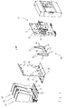
- a tripolar switchgear 10 is composed of a drive mechanism 12 and three identical cutoff modules 14, 16, 18, arranged side by side on the same side of a partition 20 separating them from the drive mechanism. 12.
- the partition 20 is constituted by a sheet having three windows 22, 24, 26 and rests on a second plate 28 arranged at right angles and acting as a base.
- the partition 20 is at ground potential and provides electrical protection to people.
- the drive mechanism 12 may be of any known type having a pole shaft. It may be for example a mechanism of the type described in the document EP-A-0 222 645 , provided with an arming and closure subassembly comprising a closing spring, and an opening subassembly comprising an opening spring.
- the essential point in the context of the present invention is that the mechanism comprises an output shaft, also called pole shaft.
- the mechanism 12 is fixed on a support frame 30 and provided with a pole shaft 32 supported by bearings 34 fixed to the frame 30. The frame is itself fixed to the partition 20.
- the pole shaft 32 comprises two double cranks 36, 38 which pass through the wall of the chassis through slots and allow the articulation between the shaft of the poles 32 and a transmission rod 40.
- the transmission rod 40 is constituted by a flat part forming two double vee arms 42, 44, spaced from one another, and connected on the diverging end side by a base 46.
- Each vee arm 42, 44 supports, at its convergent end, a pair of lugs 50, 52 provided with coaxial bores, forming bearings.
- the cranks 36, 38 also comprise coaxial bores forming bearings, so that a hinge-type pivot connection is obtained between the double cranks 36, 38 of the pole shaft 32 and the rod 40 by insertion of pins 54 into each other.
- the base 46 supports three pairs of tabs 60, 62, 64 provided with coaxial bores, forming bearings. These tabs allow, by insertion of axes 66, a hinge type connection with three double levers 70, 72, 74 belonging to the three polar modules 14, 16, 18 of the apparatus, which pass through the windows 22, 24, 26 of the partition 20.
- the module 18 comprises a vacuum interrupter 80 supported by a frame 82.
- the frame 82 is fixed to the wall 20 and the base 28, so that the frame 30, the plates 20, 28 and the frames 82 of the three poles form together a support 83 for the other parts of the apparatus.
- Two connection pads 84, 86, fixed to the frame 82, are intended to electrically connect the lamp 80 to a busbar (not shown).
- the generic expression of a vacuum bulb designates a subset of known type, comprising a cylindrical body 88 forming a chamber in which there is a relative vacuum and which encloses a pair of separable contacts 90, 92 connected to the connection pads.
- the body 88 is itself divided into a medial insulating section 94 of insulating material, a first metal end section constituting a first closure flange 96, and a second metal end section constituting a second flange of closing 98.
- the contact 92 is fixed and connected to the second flange 98.
- the other contact 90 constitutes an axial end of a rod 100 movable in translation along its axis and through the body 88 of the bulb through an orifice of the flange 96.
- the electrical connection of the rod 100 to the busbar is ensured by means of a flexible electrical connection 104, one end of which also constitutes the connection pad 84.
- the rod 100 is connected to the double lever 74, via an insulating arm 110.
- the insulating arm comprises a plastic body 112 overmolding on the one hand the head of a first threaded rod 114, and secondly the head of a second threaded rod 116 located in the axial extension of the first.
- the first threaded rod 114 is screwed into a threaded blind hole located at the end of the rod 100 of the bulb 80.
- On the second threaded rod 116 is screwed a tubular adjusting nut 118.
- the nut 118 supports at one end a support plate 120 for one end of a contact pressure spring 122.
- the other end of the spring 122 bears on a second plate 124, which rests on a bar 126.
- the bar comprises a bore 128 forming a guide sleeve traversed by the tubular nut 118.
- the bar 126 freely journalled in lateral axes 130 supported by the arms of the lever 74.
- the sheath guide 128 allows both the translation of the nut 118 parallel to its axis and its free rotation.
- the nut 118 has a shoulder that rests on the bar portion 126 opposite to the second plate 124.
- the two arms of the double lever 74 pivot about an axis 132 supported by the frame 82.
- the three breaking modules 14, 16 , 18 of the apparatus 10 being arranged side by side, the pivot axes 132 of the levers 70, 72, 74 are aligned, and parallel to the pole shaft 32.
- the levers 70, 72, 74 are parallel.
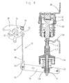
- the kinematic chain connecting the shaft of the poles 32 to the rods 100 of the three breaking modules 14, 16, 18 comprises a single connecting rod 40 connecting the pole shaft 32 and the three double levers 70, 72, 74 of the cutoff modules, and is extended in each module by an insulator 112, one end slides in a sheath 128 pivoting relative to the double lever 70, 72, 74, and the other end is integral with the rod 100 of the bulb 80.
- This kinematic chain makes it possible to define five geometrical axes of parallel rotation: a first geometric axis 140 of pivoting of the pole shaft, a second geometric axis 142 of pivoting of the levers 70, 72, 74, a third geometric axis 144 of pivoting of the connecting rod relative to the cranks of the pole shaft, a fourth geometric axis 146 pivoting the rod relative to the levers, and a fifth geometric axis 148 of pivoting bars 126 relative to the levers 70, 72, 74.
- the first axis 140 and the second axis 142 are both fixed relative to the support 83, the other axes being movable during the opening and closing sequences.
- the movement printed on the rod 100 of the bulb 80 by this mechanism in the absence of play between the moving parts would not be perfectly rectilinear with respect to the frame 82.
- the angle between the lever 70, 72, 74 and the rod 100 is always very close to the right angle, and the stroke of the rod 100 of the bulb between its open position and its closed position does not exceed a few millimeters, which corresponds to a rotation angle of the lever not exceeding a few degrees, so that in the absence of play, the radial movement of the rod 100 would be of the order of one hundredth of its axial stroke.
- this clearance is absorbed by the existing gaps between the various elements of the driveline, in particular at the axes 130, 132.
- the driveline operates in the following manner.
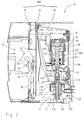
- the kinematic chain is initially in the position shown in FIG. figure 2 .
- the closing spring of the mechanism 12 drives the pole shaft 32 in the opposite direction of the clockwise, over a stroke of more than 50 °.
- the connecting rod 40 transmits this movement uniformly to the three double levers 70, 72, 74.
- the double lever pivots clockwise about the axis 132, driving the bar 126 which compresses the spring 122 through the plate 124.
- the closing force is then transmitted by the spring 122 to the movable contact 90, via the plate 120, the nut 118 and the arm 110.
- the kinematic chain is in the closed position of the figure 4 , the contacts being closed.
- the opening spring of the mechanism 12 drives the pole shaft clockwise over a travel of more than 50 °.
- the connecting rod 40 transmits this movement uniformly to the three double levers 70, 72, 74.
- the double lever pivots counterclockwise about the axis 132 on the figure 4 , directly driving the bar 126, the nut 118, the insulating arm 110 and the rod 100 of the movable contact, until reaching the open position of the figure 2 .
- the single rod 40 has a high quadratic moment with respect to an axis perpendicular to the geometric plane containing the axes of pivoting of the connecting rod with respect to the pole shaft and the double levers.
- the base 46 preserves the desired rigidity. In other words, the forces applied to the rod in its plane are not likely to induce a significant bending of the connecting rod. Therefore, the link 40 gives the kinematic chain a high rigidity, so that even if the forces to be applied to different bulbs are different, their movement will nevertheless be simultaneous.
- the pole shaft 32 itself is very torsionally rigid, so that it is possible to space the two hinges connecting the connecting rod 40 to the pole shaft 32 which contributes to further reinforce the rigidity of the kinematic chain.
- the connecting rod is manufactured by cutting a sheet.
- the levers are also made of sheet metal.
- the electrical insulation is carried out in each breaking module thanks to the insulating arms. It should be noted that the insulating portion 112 of the arm is skirted so as to provide optimum insulation.
- each specific link has a base of different length and especially legs 60, 62, 64 in number and variable locations.
- the pole shaft 32 remains identical regardless of the spacing between the polar modules, which means that the mechanism 12 can be pre-assembled at the factory and forms a functional unit for the entire range.
- the cutoff modules 14, 16, 18 are identical, regardless of the chosen spacing. This makes it possible to defer fitting of the equipment until the choice of the customer is stopped.
- the number of modules is not limited to three: the invention also applies to dipole devices, quadrupole, or hexapole or octopole.
- the levers 70, 72, 74 may be simple.
- the drive mechanism can be of any type: with closing springs and distinct opening, to allow a sequence closing, arming, opening, closing, opening; single spring for closing and opening.
Abstract
Description
L'invention se rapporte à un appareillage électrique de coupure multipolaire, et en particulier à un appareillage de coupure multipolaire comportant des ampoules à vide.The invention relates to an electrical switchgear device multipole, and in particular to a multipole breaking apparatus comprising vacuum ampoules.
Le document
Un objectif de l'invention est de réaliser un appareillage électrique de coupure multipolaire de conception simple comportant un support rigide pour les différentes pièces de l'appareillage.
Un autre objectif est de réaliser un appareillage dans lequel les modules de coupure peuvent être prémontés et essayés en usine, avant leur montage avec le mécanisme et la bielle de manière à améliorer la différenciation retardée.
Un autre objectif est d'accroître la modularité d'un appareillage de coupure multipolaire à modules de coupure polaires indépendants, en permettant à faible coût de changer la distance entre pôles.An object of the invention is to provide a multipole electrical switchgear of simple design comprising a rigid support for the various parts of the apparatus.
Another object is to provide an apparatus in which the breaking modules can be pre-assembled and tested at the factory, before being assembled with the mechanism and the connecting rod so as to improve the delayed differentiation.
Another objective is to increase the modularity of a multipolar switchgear with independent pole break modules, allowing low cost to change the distance between poles.
Selon l'invention, ces objectifs sont atteints grâce à un appareillage électrique de coupure multipolaire comportant :
- un support ;
- un mécanisme d'entraînement muni d'un arbre des pôles tourillonnant autour d'un premier axe géométrique fixe par rapport au support ;
- une pluralité de modules de coupure chaque module comportant :
- une paire de contacts séparables comportant au moins un contact mobile ;
- une tige mobile solidaire du contact mobile ;
- un levier de transmission pivotant autour d'un deuxième axe géométrique parallèle au premier axe géométrique, ledit deuxième axe géométrique étant commun à l'ensemble des modules de coupure et fixe par rapport au support ;
- des moyens de liaison du levier de transmission à ladite tige ;
- a support ;
- a drive mechanism provided with a pole shaft journalled about a first geometric axis fixed relative to the support;
- a plurality of cutoff modules each module comprising:
- a pair of separable contacts having at least one movable contact;
- a movable rod integral with the movable contact;
- a transmission lever pivoting about a second geometric axis parallel to the first geometric axis, said second geometric axis being common to all of the cutoff modules and fixed relative to the support;
- connecting means of the transmission lever to said rod;
Selon une réalisation particulière de l'invention, le(s) bâti(s) est (sont) fixé(s) à la cloison et au socle.According to a particular embodiment of the invention, the frame (s) is (are) fixed (s) to the partition and the base.
Selon une autre caractéristique, le châssis précité est fixé à la cloison.According to another characteristic, the aforementioned frame is fixed to the partition.
Selon une autre caractéristique, le(s) bâti(s) comporte(nt) des paliers destinés à assurer le pivotement respectivement du (des) levier(s) de transmission autour du deuxième axe de pivotement précité. Les modules de coupure peuvent alors être prémontés et essayés en usine, avant leur montage avec le mécanisme et la bielle. Ceci contribue à améliorer la différenciation retardée.According to another characteristic, the frame (s) comprise (s) bearings for pivoting respectively (the) lever (s) transmission about the second pivot axis aforementioned. The cut-off modules can then be pre-assembled and tested at the factory, before assembly with the mechanism and the connecting rod. This helps to improve the delayed differentiation.
D'autres avantages et caractéristiques ressortiront plus clairement de la description qui va suivre, d'un mode particulier de réalisation de l'invention, donné à titre d'exemple non limitatif, et représenté aux dessins annexés sur lesquels :
- la
figure 1 représente une vue éclatée d'un appareillage de coupure selon un mode de réalisation de l'invention, montrant en particulier un mécanisme d'entraînement et des modules de coupure ; - la
figure 2 représente une vue en coupe de l'appareillage de lafigure 1 , en position d'ouverture ; - la
figure 3 représente une vue en perspective d'une chaîne cinématique de transmission reliant le mécanisme aux modules de coupure ; - la
figure 4 représente une vue de côté de la chaîne cinématique, en position de fermeture.
- the
figure 1 represents an exploded view of a switchgear according to one embodiment of the invention, showing in particular a drive mechanism and breaking modules; - the
figure 2 represents a sectional view of the apparatus of thefigure 1 , in the open position; - the
figure 3 represents a perspective view of a transmission kinematic chain connecting the mechanism to the breaking modules; - the
figure 4 represents a side view of the kinematic chain, in the closed position.
En référence aux
Le mécanisme d'entraînement 12 peut être de tout type connu comportant un arbre des pôles. Il peut s'agir par exemple d'un mécanisme du type décrit dans le document
Comme l'illustre la
Les trois modules de coupure étant identiques, seul le module 18 sera décrit. Comme l'illustre la
A l'extérieur de l'enceinte, la tige 100 est reliée au levier double 74, par l'intermédiaire d'un bras isolant 110. Le bras isolant comporte un corps en matière plastique 112 surmoulant d'une part la tête d'une première tige filetée 114, et d'autre part la tête d'une deuxième tige filetée 116 située dans le prolongement axial de la première. La première tige filetée 114 est vissée dans un trou borgne taraudé situé à l'extrémité de la tige 100 de l'ampoule 80. Sur la deuxième tige filetée 116 est vissé un écrou tubulaire 118 de réglage. L'écrou 118 supporte à une extrémité une assiette de support 120 pour une extrémité d'un ressort de pression de contact 122. L'autre extrémité du ressort 122 porte sur une deuxième assiette 124, qui repose sur un barreau 126. Le barreau comporte un alésage 128 formant un fourreau de guidage traversé par l'écrou tubulaire 118. Le barreau 126 tourillonne librement dans des axes latéraux 130 supportés par les bras du levier 74. Le fourreau de guidage 128 autorise à la fois la translation de l'écrou 118 parallèlement à son axe et sa libre rotation. L'écrou 118 comporte un épaulement qui vient reposer sur la partie barreau 126 opposée à la deuxième assiette 124. Les deux bras du levier double 74 pivotent autour d'un axe 132 supporté par le bâti 82. Les trois modules de coupure 14, 16, 18 de l'appareillage 10 étant disposés côte à côte, les axes de pivotement 132 des leviers 70, 72, 74 sont alignés, et parallèles à l'arbre des pôles 32. Les leviers 70, 72, 74 sont parallèles.Outside the enclosure, the
Ainsi, la chaîne cinématique reliant l'arbre des pôles 32 aux tiges 100 des trois modules de coupure 14, 16, 18 comporte une bielle unique 40 de liaison entre l'arbre de pôles 32 et les trois leviers doubles 70, 72, 74 des modules de coupure, et est prolongé dans chaque module par un isolant 112, dont une extrémité coulisse dans un fourreau 128 tourillonnant par rapport au levier double 70, 72, 74, et l'autre extrémité est solidaire de la tige 100 de l'ampoule 80. Cette chaîne cinématique permet de définir cinq axes géométriques de rotation parallèle : un premier axe géométrique 140 de pivotement de l'arbre des pôles, un deuxième axe géométrique 142 de pivotement des leviers 70, 72, 74, un troisième axe géométrique 144 de pivotement de la bielle par rapport aux manivelles de l'arbre des pôles, un quatrième axe géométrique 146 de pivotement de la bielle par rapport aux leviers, et un cinquième axe géométrique 148 de pivotement des barreaux 126 par rapport aux leviers 70, 72, 74. Le premier axe 140 et le deuxième axe 142 sont tout deux fixes par rapport au support 83, les autres axes étant mobile pendant les séquences d'ouverture et de fermeture.Thus, the kinematic chain connecting the shaft of the
En toute rigueur, le mouvement imprimé à la tige 100 de l'ampoule 80 par ce mécanisme en l'absence de jeu entre les pièces mobiles ne serait pas parfaitement rectiligne par rapport au bâti 82. Toutefois, l'angle entre le levier 70, 72, 74 et la tige 100 est toujours très proche de l'angle droit, et la course de la tige 100 de l'ampoule entre sa position d'ouverture et sa position de fermeture ne dépasse pas quelques millimètres, ce qui correspond à un angle de rotation du levier ne dépassant pas quelques degrés, de sorte qu'en l'absence de jeu, le débattement radial de la tige 100 serait de l'ordre du centième de sa course axiale. Dans le mode de réalisation décrit, ce débattement est absorbé par les jeux existants entre les divers éléments de la chaîne cinématique, notamment au niveau des axes 130, 132. Toutefois, si l'on souhaitait une course plus importante, il serait possible de guider le barreau 126 dans un oblong du levier 90, 92, 94.Strictly speaking, the movement printed on the
La chaîne cinématique fonctionne de la manière suivante. Lorsque les contacts sont séparés et le mécanisme ouvert, la chaîne cinématique se trouve initialement dans la position représentée sur la
A l'ouverture, le ressort d'ouverture du mécanisme 12 entraîne l'arbre des pôles dans le sens des aiguilles d'une montre, sur une course de plus de 50°. La bielle 40 transmet ce mouvement de manière uniforme aux trois leviers doubles 70, 72, 74. Dans chacun des modules de coupure, le levier double pivote dans le sens contraire des aiguilles d'une montre autour de l'axe 132 sur la
La bielle unique 40 possède un moment quadratique élevé par rapport à un axe perpendiculaire au plan géométrique contenant les axes de pivotement de la bielle par rapport à l'arbre des pôles et aux leviers doubles. Bien que la structure de la bielle ait été allégée pour diminuer sa masse, la base 46 préserve la rigidité recherchée. En d'autres termes, les efforts appliqués à la bielle dans son plan ne sont pas susceptibles d'induire une flexion notable de la bielle. Par conséquent, la bielle 40 confère à la chaîne cinématique une grande rigidité, de sorte que même si les efforts à appliquer aux différentes ampoules sont différents, leur mouvement sera néanmoins simultané. Par construction, l'arbre des pôles 32 est lui-même très rigide en torsion, de sorte qu'il est possible d'espacer les deux charnières joignant la bielle 40 à l'arbre des pôles 32 ce qui contribue à renforcer encore la rigidité de la chaîne cinématique.The
La bielle est fabriquée par découpe d'une tôle. Les leviers sont également réalisés en tôle. L'isolation électrique est réalisée dans chaque module de coupure grâce aux bras isolants. Il est à noter que la partie isolante 112 du bras est conformée en jupe de manière à assurer une isolation optimale.The connecting rod is manufactured by cutting a sheet. The levers are also made of sheet metal. The electrical insulation is carried out in each breaking module thanks to the insulating arms. It should be noted that the insulating
Pour modifier l'entraxe des modules polaires, il suffit de changer la bielle et, le cas échéant, la paroi 20, qui sont des pièces à très faible coût. Chaque bielle spécifique a une base de longueur différente et surtout des pattes 60, 62, 64 en nombre et emplacements variables. Par contre, la distance entre les pattes 50, 52 assurant la liaison charnière avec les manivelles de l'arbre des pôles reste constante. Ainsi, l'arbre des pôles 32 reste identique quel que soit l'entraxe des modules polaires, ce qui signifie que le mécanisme 12 peut être prémonté en usine et forme une unité fonctionnelle pour l'ensemble de la gamme. De même, les modules de coupure 14, 16, 18 sont identiques, quel que soit l'entraxe choisi. Ceci permet de différer le montage de l'appareillage jusqu'à ce que le choix du client soit arrêté.To change the spacing of the polar modules, simply change the connecting rod and, if necessary, the
Naturellement, diverses modifications sont possibles. Le nombre de modules n'est pas limité à trois : l'invention s'applique également à des appareillages dipolaires, quadripolaires, voire hexapolaires ou octopolaires. Les leviers 70, 72, 74 peuvent être simples. Le mécanisme d'entraînement peut être de tout type : à ressorts de fermeture et d'ouverture distincts, pour permettre une séquence fermeture, armement, ouverture, fermeture, ouverture ; à un seul ressort permettant la fermeture et l'ouverture.Naturally, various modifications are possible. The number of modules is not limited to three: the invention also applies to dipole devices, quadrupole, or hexapole or octopole. The
Claims (11)
Applications Claiming Priority (2)
| Application Number | Priority Date | Filing Date | Title |
|---|---|---|---|
| FR0004162A FR2807204B1 (en) | 2000-03-31 | 2000-03-31 | ELECTRIC MULTIPOLAR CUTTING APPARATUS PROVIDED WITH A DRIVE MECHANISM AND CUTTING MODULES |
| EP01410033A EP1139368B1 (en) | 2000-03-31 | 2001-03-30 | Electrical multiphase interrupting device with a driving mechanism and switching modules |
Related Parent Applications (2)
| Application Number | Title | Priority Date | Filing Date |
|---|---|---|---|
| EP01410033.3 Division | 2001-03-30 | ||
| EP01410033A Division EP1139368B1 (en) | 2000-03-31 | 2001-03-30 | Electrical multiphase interrupting device with a driving mechanism and switching modules |
Publications (3)
| Publication Number | Publication Date |
|---|---|
| EP1968088A2 true EP1968088A2 (en) | 2008-09-10 |
| EP1968088A3 EP1968088A3 (en) | 2008-10-29 |
| EP1968088B1 EP1968088B1 (en) | 2013-09-04 |
Family
ID=8848752
Family Applications (2)
| Application Number | Title | Priority Date | Filing Date |
|---|---|---|---|
| EP01410033A Expired - Lifetime EP1139368B1 (en) | 2000-03-31 | 2001-03-30 | Electrical multiphase interrupting device with a driving mechanism and switching modules |
| EP08011061.2A Revoked EP1968088B1 (en) | 2000-03-31 | 2001-03-30 | Multipolar electrical switch equipped with an operating mechanism and switching modules |
Family Applications Before (1)
| Application Number | Title | Priority Date | Filing Date |
|---|---|---|---|
| EP01410033A Expired - Lifetime EP1139368B1 (en) | 2000-03-31 | 2001-03-30 | Electrical multiphase interrupting device with a driving mechanism and switching modules |
Country Status (8)
| Country | Link |
|---|---|
| US (1) | US6506990B2 (en) |
| EP (2) | EP1139368B1 (en) |
| CN (1) | CN1172340C (en) |
| DE (1) | DE60137880D1 (en) |
| EA (1) | EA003758B1 (en) |
| FR (1) | FR2807204B1 (en) |
| MY (1) | MY117468A (en) |
| PL (1) | PL197700B1 (en) |
Cited By (1)
| Publication number | Priority date | Publication date | Assignee | Title |
|---|---|---|---|---|
| EP3767657A1 (en) | 2019-07-17 | 2021-01-20 | Schneider Electric Industries SAS | Architecture of an electrical switchgear |
Families Citing this family (17)
| Publication number | Priority date | Publication date | Assignee | Title |
|---|---|---|---|---|
| US6373358B1 (en) * | 2000-05-09 | 2002-04-16 | Eaton Corporation | Power circuit breaker having molded insulative casing with a dead front |
| US6657150B1 (en) * | 2002-06-14 | 2003-12-02 | Eaton Corporation | Shorting switch and system to eliminate arcing faults in power distribution equipment |
| US6724604B2 (en) * | 2002-06-14 | 2004-04-20 | Eaton Corporation | Shorting switch and system to eliminate arcing faults in power distribution equipment |
| US6747234B2 (en) * | 2002-07-23 | 2004-06-08 | Maysteel Llc | High voltage interrupter |
| AU2003270192A1 (en) * | 2003-09-13 | 2005-04-21 | Abb Technology Ag | Device for actuating an electrical switchgear |
| DE102005016544A1 (en) * | 2005-04-08 | 2006-10-12 | Abb Patent Gmbh | Modular front for a switchgear module, switchgear module and electrical switchgear |
| EP2255423B1 (en) * | 2008-02-15 | 2016-04-13 | ABB Technology Ltd | A configurable circuit breaker |
| CN101599388B (en) * | 2009-07-13 | 2012-06-27 | 浙江雷安电气有限公司 | Insulating pull rod for breaker |
| KR101100707B1 (en) * | 2009-12-31 | 2012-01-02 | 엘에스산전 주식회사 | Vacuum circuit breaker |
| DE102010011997B4 (en) * | 2010-03-18 | 2023-02-02 | Siemens Aktiengesellschaft | Drive device for a tensioning shaft of a spring force drive of an electric switch and electric switch with such a drive device |
| EP2437277B1 (en) * | 2010-09-29 | 2014-12-24 | ABB Technology AG | Medium voltage circuit breaker arrangement |
| FR2972072B1 (en) * | 2011-02-25 | 2013-02-15 | Schneider Electric Ind Sas | DEVICE FOR CONTROLLING AT LEAST ONE MOBILE CONTACT AND ELECTRIC MULTIPOLAR CUTTING APPARATUS COMPRISING SUCH A DEVICE |
| KR101786518B1 (en) * | 2011-04-27 | 2017-10-18 | 엘에스산전 주식회사 | Extinguishing portion for gas insulation switch |
| JP5755034B2 (en) * | 2011-06-08 | 2015-07-29 | 日本高圧電気株式会社 | High pressure switch |
| FR2980909B1 (en) | 2011-09-30 | 2016-08-05 | Schneider Electric Ind Sas | DEVICE FOR RELEASING THE MOTORIZATION OF THE RESET DEVICE OF THE DEVICE FOR CLOSING CONTACTS IN AN ELECTRICAL PROTECTION DEVICE AND APPARATUS COMPRISING THE SAME |
| FR2984589A1 (en) | 2011-12-16 | 2013-06-21 | Schneider Electric Ind Sas | DEVICE FOR CONTROLLING THE MOTORIZATION OF THE RESET DEVICE OF THE DEVICE FOR CLOSING CONTACTS IN AN ELECTRICAL PROTECTION DEVICE AND APPARATUS COMPRISING IT |
| FR3101191B1 (en) | 2019-09-25 | 2023-05-12 | Schneider Electric Ind Sas | Determination of a state of a breaking device |
Citations (2)
| Publication number | Priority date | Publication date | Assignee | Title |
|---|---|---|---|---|
| EP0222645A1 (en) | 1985-10-31 | 1987-05-20 | Merlin Gerin | Operating mechanism for a circuit breaker provided with an energy storing device |
| EP0346603A1 (en) | 1988-06-14 | 1989-12-20 | Sprecher Energie AG | Vacuum circuit breaker |
Family Cites Families (12)
| Publication number | Priority date | Publication date | Assignee | Title |
|---|---|---|---|---|
| US4168414A (en) * | 1975-03-06 | 1979-09-18 | Mcgraw-Edison Company | Protective switch device and operating mechanism therefor |
| US4104496A (en) * | 1977-01-18 | 1978-08-01 | Tokyo Shibaura Electric Co., Ltd. | Vacuum interrupter device |
| JPS57147829A (en) * | 1981-03-06 | 1982-09-11 | Tokyo Shibaura Electric Co | Vacuum breaker |
| ZA848788B (en) * | 1983-11-29 | 1985-07-31 | Westinghouse Electric Corp | Vacuum contractor with integral shaft |
| DE3915522A1 (en) * | 1989-05-11 | 1990-11-15 | Siemens Ag | DRIVE DEVICE FOR A VACUUM SWITCH TUBE WITH A CONTACT SPRING |
| DE4010843A1 (en) * | 1990-04-04 | 1991-10-10 | Sachsenwerk Ag | SUPPORT SWITCH |
| US5175403A (en) * | 1991-08-22 | 1992-12-29 | Cooper Power Systems, Inc. | Recloser means for reclosing interrupted high voltage electric circuit means |
| DE9213143U1 (en) * | 1992-09-25 | 1993-03-25 | Siemens Ag, 8000 Muenchen, De | |
| US5852266A (en) * | 1993-07-14 | 1998-12-22 | Hitachi, Ltd. | Vacuum circuit breaker as well as vacuum valve and electric contact used in same |
| US5444201A (en) * | 1993-11-22 | 1995-08-22 | Eaton Corporation | Multiple electrode structure for a vacuum interrupter |
| US6144005A (en) * | 1997-07-23 | 2000-11-07 | Hitachi, Ltd. | Vacuum switch and a vacuum switchgear using the same |
| JP2000268683A (en) * | 1999-01-14 | 2000-09-29 | Toshiba Corp | Operating device for switch |
-
2000
- 2000-03-31 FR FR0004162A patent/FR2807204B1/en not_active Expired - Lifetime
-
2001
- 2001-02-27 MY MYPI20010853A patent/MY117468A/en unknown
- 2001-02-28 US US09/794,345 patent/US6506990B2/en not_active Expired - Lifetime
- 2001-03-28 CN CNB011121068A patent/CN1172340C/en not_active Expired - Lifetime
- 2001-03-29 PL PL346749A patent/PL197700B1/en not_active IP Right Cessation
- 2001-03-30 DE DE60137880T patent/DE60137880D1/en not_active Expired - Lifetime
- 2001-03-30 EP EP01410033A patent/EP1139368B1/en not_active Expired - Lifetime
- 2001-03-30 EP EP08011061.2A patent/EP1968088B1/en not_active Revoked
- 2001-03-30 EA EA200100306A patent/EA003758B1/en not_active IP Right Cessation
Patent Citations (2)
| Publication number | Priority date | Publication date | Assignee | Title |
|---|---|---|---|---|
| EP0222645A1 (en) | 1985-10-31 | 1987-05-20 | Merlin Gerin | Operating mechanism for a circuit breaker provided with an energy storing device |
| EP0346603A1 (en) | 1988-06-14 | 1989-12-20 | Sprecher Energie AG | Vacuum circuit breaker |
Cited By (2)
| Publication number | Priority date | Publication date | Assignee | Title |
|---|---|---|---|---|
| EP3767657A1 (en) | 2019-07-17 | 2021-01-20 | Schneider Electric Industries SAS | Architecture of an electrical switchgear |
| FR3098976A1 (en) | 2019-07-17 | 2021-01-22 | Schneider Electric Industries Sas | Architecture of an electrical switch device |
Also Published As
| Publication number | Publication date |
|---|---|
| EA200100306A3 (en) | 2001-12-24 |
| EP1968088B1 (en) | 2013-09-04 |
| EA003758B1 (en) | 2003-08-28 |
| CN1172340C (en) | 2004-10-20 |
| PL346749A1 (en) | 2001-10-08 |
| EP1139368B1 (en) | 2009-03-11 |
| FR2807204B1 (en) | 2002-05-24 |
| US20010025776A1 (en) | 2001-10-04 |
| FR2807204A1 (en) | 2001-10-05 |
| EP1139368A1 (en) | 2001-10-04 |
| PL197700B1 (en) | 2008-04-30 |
| US6506990B2 (en) | 2003-01-14 |
| DE60137880D1 (en) | 2009-04-23 |
| EP1968088A3 (en) | 2008-10-29 |
| CN1319862A (en) | 2001-10-31 |
| MY117468A (en) | 2004-06-30 |
| EA200100306A2 (en) | 2001-10-22 |
Similar Documents
| Publication | Publication Date | Title |
|---|---|---|
| EP1968088B1 (en) | Multipolar electrical switch equipped with an operating mechanism and switching modules | |
| EP2178099B1 (en) | High- or medium-voltage electrical switching apparatus with two switches comprising driving means shared with the mobile contacts of the switches | |
| FR2808117A1 (en) | ELECTRICAL SWITCHING APPARATUS COMPRISING A VACUUM BULB AND A FLEXIBLE ELECTRICAL CONNECTION | |
| EP1946348B1 (en) | Ground disconnect switch and method for making same | |
| EP0540971B1 (en) | High- or medium-voltage circuit breaker with triple motion | |
| EP2335262A1 (en) | Electric switching apparatus provided with two switches, such as a busbar sectionalising switch and an earthing switch, and including a driving means common to the mobile contacts of the switches | |
| EP1571685A1 (en) | Mounting device for a shield in an electrical interrupter, preferably in a vacuum interrupter | |
| EP1139367B1 (en) | Load-breaking module with vacuum bottle and fixing means, and switchgear using such a module | |
| EP0693763B1 (en) | M.T. electrical switches | |
| EP2717284B1 (en) | Operating device of an electric protection apparatus and electric protection apparatus comprising same | |
| FR2716747A1 (en) | Modular spring for high amperage circuit breaker | |
| EP1507274B1 (en) | Earthing switch | |
| EP2492941B1 (en) | Device for controlling at least one mobile contact and multipolar electronic switchgear comprising such a device | |
| EP1998352B1 (en) | Contact device for an electrical appliance and auxiliary signalling comprising such a device | |
| EP0704872B1 (en) | Middle voltage interruptor or circuit breaker | |
| EP2023361B1 (en) | Three-phase switching device in metal casing with reduced dimensions and phase transmission forces | |
| FR2576141A1 (en) | LOW VOLTAGE CIRCUIT BREAKER, WITH HOLDING LATCH ARRANGED IN A SEPARATE BEDROOM | |
| FR2647948A1 (en) | ELECTRIC SWITCH WITH ROTATING ARC | |
| WO2011135034A1 (en) | Compact ground isolator | |
| FR2857779A1 (en) | Multipole circuit breaker for energy distribution, has connection mechanism to allow electromagnetic repulsion in one mobile unit to act in certain direction by series of electromagnetic repulsions in other mobile units | |
| EP3273458B1 (en) | Device for damping the movement of a control shaft in an electrical protection device and electrical protection device comprising such a damping device | |
| EP3020058B1 (en) | Circuit breaker with removable screen | |
| FR3093227A1 (en) | Contact control device of a vacuum interrupter for electrical connection device | |
| CH370135A (en) | High voltage rotary disconnector |
Legal Events
| Date | Code | Title | Description |
|---|---|---|---|
| PUAI | Public reference made under article 153(3) epc to a published international application that has entered the european phase |
Free format text: ORIGINAL CODE: 0009012 |
|
| AC | Divisional application: reference to earlier application |
Ref document number: 1139368 Country of ref document: EP Kind code of ref document: P |
|
| AK | Designated contracting states |
Kind code of ref document: A2 Designated state(s): DE GB IT |
|
| PUAL | Search report despatched |
Free format text: ORIGINAL CODE: 0009013 |
|
| AK | Designated contracting states |
Kind code of ref document: A3 Designated state(s): DE GB IT |
|
| 17P | Request for examination filed |
Effective date: 20081117 |
|
| 17Q | First examination report despatched |
Effective date: 20090219 |
|
| RAP1 | Party data changed (applicant data changed or rights of an application transferred) |
Owner name: SCHNEIDER ELECTRIC INDUSTRIES SAS |
|
| AKX | Designation fees paid |
Designated state(s): DE GB IT |
|
| GRAP | Despatch of communication of intention to grant a patent |
Free format text: ORIGINAL CODE: EPIDOSNIGR1 |
|
| INTG | Intention to grant announced |
Effective date: 20130604 |
|
| GRAS | Grant fee paid |
Free format text: ORIGINAL CODE: EPIDOSNIGR3 |
|
| GRAA | (expected) grant |
Free format text: ORIGINAL CODE: 0009210 |
|
| AC | Divisional application: reference to earlier application |
Ref document number: 1139368 Country of ref document: EP Kind code of ref document: P |
|
| AK | Designated contracting states |
Kind code of ref document: B1 Designated state(s): DE GB IT |
|
| REG | Reference to a national code |
Ref country code: GB Ref legal event code: FG4D Free format text: NOT ENGLISH |
|
| REG | Reference to a national code |
Ref country code: DE Ref legal event code: R096 Ref document number: 60148303 Country of ref document: DE Effective date: 20131031 |
|
| PLAZ | Examination of admissibility of opposition: despatch of communication + time limit |
Free format text: ORIGINAL CODE: EPIDOSNOPE2 |
|
| PLBI | Opposition filed |
Free format text: ORIGINAL CODE: 0009260 |
|
| PLBA | Examination of admissibility of opposition: reply received |
Free format text: ORIGINAL CODE: EPIDOSNOPE4 |
|
| 26 | Opposition filed |
Opponent name: SIEMENS AKTIENGESELLSCHAFT Effective date: 20140528 |
|
| PLAX | Notice of opposition and request to file observation + time limit sent |
Free format text: ORIGINAL CODE: EPIDOSNOBS2 |
|
| REG | Reference to a national code |
Ref country code: DE Ref legal event code: R026 Ref document number: 60148303 Country of ref document: DE Effective date: 20140528 |
|
| PLAF | Information modified related to communication of a notice of opposition and request to file observations + time limit |
Free format text: ORIGINAL CODE: EPIDOSCOBS2 |
|
| PLBB | Reply of patent proprietor to notice(s) of opposition received |
Free format text: ORIGINAL CODE: EPIDOSNOBS3 |
|
| PLCK | Communication despatched that opposition was rejected |
Free format text: ORIGINAL CODE: EPIDOSNREJ1 |
|
| APBM | Appeal reference recorded |
Free format text: ORIGINAL CODE: EPIDOSNREFNO |
|
| APBP | Date of receipt of notice of appeal recorded |
Free format text: ORIGINAL CODE: EPIDOSNNOA2O |
|
| APAH | Appeal reference modified |
Free format text: ORIGINAL CODE: EPIDOSCREFNO |
|
| APBQ | Date of receipt of statement of grounds of appeal recorded |
Free format text: ORIGINAL CODE: EPIDOSNNOA3O |
|
| PLAB | Opposition data, opponent's data or that of the opponent's representative modified |
Free format text: ORIGINAL CODE: 0009299OPPO |
|
| R26 | Opposition filed (corrected) |
Opponent name: SIEMENS AKTIENGESELLSCHAFT Effective date: 20140528 |
|
| REG | Reference to a national code |
Ref country code: DE Ref legal event code: R084 Ref document number: 60148303 Country of ref document: DE |
|
| PGFP | Annual fee paid to national office [announced via postgrant information from national office to epo] |
Ref country code: IT Payment date: 20200221 Year of fee payment: 20 Ref country code: GB Payment date: 20200318 Year of fee payment: 20 Ref country code: DE Payment date: 20200311 Year of fee payment: 20 |
|
| APBU | Appeal procedure closed |
Free format text: ORIGINAL CODE: EPIDOSNNOA9O |
|
| REG | Reference to a national code |
Ref country code: DE Ref legal event code: R064 Ref document number: 60148303 Country of ref document: DE Ref country code: DE Ref legal event code: R103 Ref document number: 60148303 Country of ref document: DE |
|
| RDAF | Communication despatched that patent is revoked |
Free format text: ORIGINAL CODE: EPIDOSNREV1 |
|
| RDAG | Patent revoked |
Free format text: ORIGINAL CODE: 0009271 |
|
| STAA | Information on the status of an ep patent application or granted ep patent |
Free format text: STATUS: PATENT REVOKED |
|
| 27W | Patent revoked |
Effective date: 20200719 |
|
| GBPR | Gb: patent revoked under art. 102 of the ep convention designating the uk as contracting state |
Effective date: 20200719 |