EP1967734A1 - Screw-type fluid machine - Google Patents
Screw-type fluid machine Download PDFInfo
- Publication number
- EP1967734A1 EP1967734A1 EP06843248A EP06843248A EP1967734A1 EP 1967734 A1 EP1967734 A1 EP 1967734A1 EP 06843248 A EP06843248 A EP 06843248A EP 06843248 A EP06843248 A EP 06843248A EP 1967734 A1 EP1967734 A1 EP 1967734A1
- Authority
- EP
- European Patent Office
- Prior art keywords
- oil
- shaft
- lubricant oil
- rotary shaft
- screw
- Prior art date
- Legal status (The legal status is an assumption and is not a legal conclusion. Google has not performed a legal analysis and makes no representation as to the accuracy of the status listed.)
- Withdrawn
Links
- 239000012530 fluid Substances 0.000 title claims description 17
- 239000000314 lubricant Substances 0.000 claims abstract description 72
- 239000000498 cooling water Substances 0.000 claims abstract description 26
- 238000003860 storage Methods 0.000 claims abstract description 23
- 230000001360 synchronised effect Effects 0.000 claims description 16
- 238000001816 cooling Methods 0.000 claims description 8
- 239000012809 cooling fluid Substances 0.000 claims description 7
- 238000011084 recovery Methods 0.000 description 14
- 238000003780 insertion Methods 0.000 description 8
- 230000037431 insertion Effects 0.000 description 8
- 238000004519 manufacturing process Methods 0.000 description 3
- 238000011144 upstream manufacturing Methods 0.000 description 3
- 230000009471 action Effects 0.000 description 2
- 238000001514 detection method Methods 0.000 description 2
- 238000006073 displacement reaction Methods 0.000 description 2
- 238000005096 rolling process Methods 0.000 description 2
- 238000007789 sealing Methods 0.000 description 2
- 239000004065 semiconductor Substances 0.000 description 2
- 230000008859 change Effects 0.000 description 1
- 239000002826 coolant Substances 0.000 description 1
- 230000007423 decrease Effects 0.000 description 1
Images



Classifications
-
- F—MECHANICAL ENGINEERING; LIGHTING; HEATING; WEAPONS; BLASTING
- F04—POSITIVE - DISPLACEMENT MACHINES FOR LIQUIDS; PUMPS FOR LIQUIDS OR ELASTIC FLUIDS
- F04C—ROTARY-PISTON, OR OSCILLATING-PISTON, POSITIVE-DISPLACEMENT MACHINES FOR LIQUIDS; ROTARY-PISTON, OR OSCILLATING-PISTON, POSITIVE-DISPLACEMENT PUMPS
- F04C29/00—Component parts, details or accessories of pumps or pumping installations, not provided for in groups F04C18/00 - F04C28/00
- F04C29/02—Lubrication; Lubricant separation
- F04C29/025—Lubrication; Lubricant separation using a lubricant pump
-
- F—MECHANICAL ENGINEERING; LIGHTING; HEATING; WEAPONS; BLASTING
- F04—POSITIVE - DISPLACEMENT MACHINES FOR LIQUIDS; PUMPS FOR LIQUIDS OR ELASTIC FLUIDS
- F04C—ROTARY-PISTON, OR OSCILLATING-PISTON, POSITIVE-DISPLACEMENT MACHINES FOR LIQUIDS; ROTARY-PISTON, OR OSCILLATING-PISTON, POSITIVE-DISPLACEMENT PUMPS
- F04C18/00—Rotary-piston pumps specially adapted for elastic fluids
- F04C18/08—Rotary-piston pumps specially adapted for elastic fluids of intermeshing-engagement type, i.e. with engagement of co-operating members similar to that of toothed gearing
- F04C18/12—Rotary-piston pumps specially adapted for elastic fluids of intermeshing-engagement type, i.e. with engagement of co-operating members similar to that of toothed gearing of other than internal-axis type
- F04C18/14—Rotary-piston pumps specially adapted for elastic fluids of intermeshing-engagement type, i.e. with engagement of co-operating members similar to that of toothed gearing of other than internal-axis type with toothed rotary pistons
- F04C18/16—Rotary-piston pumps specially adapted for elastic fluids of intermeshing-engagement type, i.e. with engagement of co-operating members similar to that of toothed gearing of other than internal-axis type with toothed rotary pistons with helical teeth, e.g. chevron-shaped, screw type
-
- F—MECHANICAL ENGINEERING; LIGHTING; HEATING; WEAPONS; BLASTING
- F04—POSITIVE - DISPLACEMENT MACHINES FOR LIQUIDS; PUMPS FOR LIQUIDS OR ELASTIC FLUIDS
- F04C—ROTARY-PISTON, OR OSCILLATING-PISTON, POSITIVE-DISPLACEMENT MACHINES FOR LIQUIDS; ROTARY-PISTON, OR OSCILLATING-PISTON, POSITIVE-DISPLACEMENT PUMPS
- F04C29/00—Component parts, details or accessories of pumps or pumping installations, not provided for in groups F04C18/00 - F04C28/00
- F04C29/02—Lubrication; Lubricant separation
- F04C29/023—Lubricant distribution through a hollow driving shaft
-
- F—MECHANICAL ENGINEERING; LIGHTING; HEATING; WEAPONS; BLASTING
- F04—POSITIVE - DISPLACEMENT MACHINES FOR LIQUIDS; PUMPS FOR LIQUIDS OR ELASTIC FLUIDS
- F04C—ROTARY-PISTON, OR OSCILLATING-PISTON, POSITIVE-DISPLACEMENT MACHINES FOR LIQUIDS; ROTARY-PISTON, OR OSCILLATING-PISTON, POSITIVE-DISPLACEMENT PUMPS
- F04C2220/00—Application
- F04C2220/10—Vacuum
-
- F—MECHANICAL ENGINEERING; LIGHTING; HEATING; WEAPONS; BLASTING
- F04—POSITIVE - DISPLACEMENT MACHINES FOR LIQUIDS; PUMPS FOR LIQUIDS OR ELASTIC FLUIDS
- F04C—ROTARY-PISTON, OR OSCILLATING-PISTON, POSITIVE-DISPLACEMENT MACHINES FOR LIQUIDS; ROTARY-PISTON, OR OSCILLATING-PISTON, POSITIVE-DISPLACEMENT PUMPS
- F04C29/00—Component parts, details or accessories of pumps or pumping installations, not provided for in groups F04C18/00 - F04C28/00
- F04C29/04—Heating; Cooling; Heat insulation
Definitions
- the present invention relates to a screw-type fluid machine such as a vacuum pump, that is used in, for example, a semiconductor manufacturing process.
- a screw-type vacuum pump described in Patent Document 1 has been known as a screw-type fluid machine.
- the screw-type vacuum pump according to Patent Document 1 includes a pair of screw-shaped rotors, which are adjacent to and meshed with each other, in the casing. Each rotor has a rotary shaft.
- the rotary shafts are supported with respect to the casing, which operates as a shaft retainer, with upper bearings and lower bearings.
- a synchronous gear is fixed to each rotary shaft, and the synchronous gears are meshed with each other.
- a lubricant oil passage extending in the axial direction is formed in the interior of the each rotary shaft, and the lubricant oil passage functions as a centrifugal pump.
- the lubricant oil passage has an inlet open to the lower end of the rotary shaft and an outlet open to the circumferential surface of the rotary shaft above the upper bearing.
- a heat exchanger is provided near the inlet of the lubricant oil passage.
- Lubricant oil is stored in the casing, and the lower end of the rotary shaft is immersed in the lubricant oil stored therein. Further, a cooling water pipe is provided in the casing, and heat exchange takes place between the cooling water and the lubricant oil in the heat exchanger.
- the centrifugal pump draws up lubricant oil stored in the casing.
- the lubricant oil is subjected to heat exchange and cooled down by the heat exchanger when being drawn up by the centrifugal pump.
- the lubricant oil thus drawn up comes out through the outlet of the lubricant oil passage and flows down to the upper bearing to cool the upper bearing.
- the lubricant oil flows down from the upper bearing along the rotary shaft and is again stored in the casing. With such circulation of the lubricant oil, the upper and lower bearings, the rotary shaft, and other members, are cooled.
- the rotary shaft is thermally expanded due to, for example, load is applied to the bearings, by which the rotary shaft is supported with respect to the casing, in the axial direction.
- load is applied to the bearings, by which the rotary shaft is supported with respect to the casing, in the axial direction.
- the bearings and rotary shafts are cooled by the lubricant oil, such thermal expansion is suppressed, and the load on the bearings is reduced.
- bearings are provided between the casing and the rotary shaft so as to allow displacement of the rotary shaft in the axial direction with respect to the casing, load resulting from thermal expansion of the rotary shafts can be prevented from being applied to the bearings in the axial direction.
- load resulting from thermal expansion of the rotary shafts can be prevented from being applied to the bearings in the axial direction.
- a screw-type fluid machine that includes a housing, a pair of screw-shaped rotors which are accommodated in the housing and are meshed with each other, a pair of rotary shafts which are connected to both rotors so as to become coaxial with the rotors respectively, and a pair of cylindrical shaft retainers extending in the housing.
- Each rotary shaft has an end portion protruding from the housing.
- Each shaft retainer has a first end portion and a second end portion, and also has a through hole into which one of the rotary shafts is inserted.
- the first bearing is mounted in the through hole at the first end portion
- the second bearing is mounted in the through hole at the second end portion.
- Each pair of the first and second bearings supports the corresponding rotary shaft rotatably with respect to the shaft retainer.
- the first and second bearings are fixed in the axial direction with respect to the corresponding rotary shafts and the shaft retainers.
- Synchronous gears are provided at the end portions of both rotary shafts protruding from the housing, respectively.
- a gear case accommodates the synchronous gears, and the gear case defines an oil reservoir space in which lubricant oil can be stored.
- a cooling portion cools down the lubricant oil using a cooling fluid.
- the flow rate changing portion controls the flow rate of the cooling fluid.
- a temperature sensor is provided in the oil reservoir space and detects the temperature of the lubricant oil.
- a control portion controls the flow rate changing portion in accordance with the temperature detected by the temperature sensor so that the temperature of lubricant oil in the oil reservoir space is kept constant.
- a screw-type fluid machine is a screw-type vacuum pump 10 which is vertically placed and used for semiconductor manufacturing (hereinafter simply referred to as a "vacuum pump").
- the vacuum pump 10 has a housing 14 having an upper housing member 11, a rotor housing member 12, and a lower housing member 13.
- the housing 14 forms the shell of the vacuum pump 10.
- the upper housing member 11 is connected to the upper end of the rotor housing member 12, and the lower housing member 13 is connected to the lower end of the rotor housing member 12.
- a suction port 15 to draw in a compressive fluid is formed in the upper housing member 11 so as to communicate with the interior of the housing 14.
- the lower housing member 13 is provided with a discharge port 16 to discharge the compressive fluid.
- the discharge port 16 communicates with the interior of the housing 14.
- the lower housing member 13 is provided with an extension part 13a caused to extend sideways, and a drive motor 17 operating as a drive source is installed on the extension part 13a.
- a gear case 18 to cover the lower housing member 13 including the extension part 13a from downward thereof is connected to the lower housing member 13.
- An operation chamber is formed by the rotors 21, 31 and the housing 14.
- the male rotor 21 has an insertion hole 22 extending from the discharge port 16 toward the suction port 15 and an connection hole 23, the diameter of which is smaller than that of the insertion hole 22, extending upward from the upper end of the insertion hole 22.
- a rotary shaft 25 passing through the lower housing member 13 is inserted into the connection hole 23.
- the male rotor 21 and the rotary shaft 25 are connected to each other by using a stop plate 26 and a connection bolt 27. Accordingly, the male rotor 21 and the rotary shaft 25 rotate integrally.
- the female rotor 31 shown in Fig. 2 is provided with an insertion hole 32 and a connection hole 33, and is connected to a rotary shaft 35 by using a stop plate 36 and a connection bolt 37.
- Each of the respective rotors 21 and 31 is coaxial with the corresponding one of the rotary shafts 25 and 35.
- the lower housing member 13 has a pair of cylindrical shaft retainers 28, 38 extending upward, and as shown in Fig. 2 , the proximal portions of the shaft retainers 28, 38 are linked with each other and integrated.
- the shaft retainers 28, 38 are fixed to the lower housing member 13 by fixing bolts 41.
- the shaft retainer 28 is inserted into the insertion hole 22 of the male rotor 21, and a slight space is formed between the outer circumferential surface of the shaft retainer 28 and the inner-circumferential surface of the insertion hole 22.
- the shaft retainer 38 is inserted into the insertion hole 32 of the female rotor 31, and a slight space is also formed between the outer circumferential surface of the shaft retainer 38 and the inner circumferential surface of the insertion hole 32.
- a through hole 29 extending in the axial direction is formed at the center of the shaft retainer 28, and the rotary shaft 25 for the male rotor 21 is inserted into the through hole 29.
- a pair of upper and lower bearing portions 42, 43 consisting of roller bearings are provided between the rotary shaft 25 and the shaft retainer 28.
- the bearing portions 42, 43 are disposed at the upper and lower parts of the shaft retainer 28.
- the upper bearing portion 42 is a distal bearing portion or a second bearing portion
- the lower roller bearing 43 is a proximal bearing portion or a first bearing portion.
- An upper large diameter hole 29a having a larger diameter than the diameter of the through hole 29 is formed at the upper end portion (the second end portion) of the shaft retainer 28, continuous to the through hole 29.
- the distal bearing portion 42 is disposed in the upper large diameter hole 29a. Also, the portion between the distal bearing 42 and the proximal bearing 43 at the rotary shaft 25 has a slightly larger diameter than that of the upper and lower parts of the rotary shaft 25. As shown in Fig. 3 , the portion of the rotary shaft 25, the diameter of which changes, forms a distal step portion 25a and a proximal step portion 25b.
- a sealing member 30 is located between the rotary shaft 25 and the shaft retainer 28 at a position above the distal bearing portion 42.
- a lower large diameter hole 29b having a larger diameter than that of the through hole 29 is provided at the lower end portion (the first end portion) of the shaft retainer 28, continuous to the through hole 29.
- the proximal bearing portion 43 is disposed in the lower large diameter hole 29b.
- each of the distal bearing portion 42 and the proximal bearing portion 43 is structured by stacking two roller bearings each one being a single row.
- the distal bearing portion 42 is composed of a combination of two angular ball bearings 42a, 42b. As shown in Fig. 3 , both bearings 42a, 42b are disposed in the upper large diameter hole 29a in a state of Duplex Back-to-back. The outer rings of both bearings 42a, 42b are pressure-fitted to the upper large diameter hole 29a and fixed to the shaft retainer 28. In addition, the inner rings of both bearings 42a, 42b are pressure-fitted to the rotary shaft 25.
- the inner ring of the angular ball bearing 42b is pressed against the distal step portion 25a of the rotary shaft 25, and the inner ring of the angular ball bearing 42a is pressed against the inner ring of the angular ball bearing 42b by a nut 49a screwed in the rotary shaft 25.
- the rolling elements of the angular ball bearings 42a, 42b are in contact with the inner and outer rings without any space in either of the axial direction or the radial direction.
- the angular ball bearings 43a, 43b are disposed at the lower large diameter hole 29b at the proximal bearing portion 43 in a state of Duplex Back-to-back.
- the outer rings of the bearings 43a, 43b are pressure-fitted to the lower large diameter hole 29b and are fixed to the shaft retainer 28.
- the inner ring of the angular ball bearing 43a is pressed against the proximal step portion 25b of the rotary shaft 25, and the inner ring of the angular ball bearing 43b is pressed against the inner ring of the angular ball bearing 43a by a nut 49b screwed in the rotary shaft 25. Therefore, the rolling elements of the angular ball bearings 43a, 43b are in contact with the inner and outer rings without any space in either of the axial direction or the radial direction.
- the rotary shaft 25 does not move in the axial direction and the radial direction with respect to the shaft retainer 28. That is, the distal bearing portion 42 and the proximal bearing portion 43 are fixed in the axial direction by means of nuts 49a, 49b and the step portions 25a, 25b.
- the space forms a lubricant oil recovery passage 48 (hereinafter, simply referred to as an oil recovery passage 48).
- the oil recovery passage 48 causes lubricant oil 62, which is a cooling medium, to be brought into contact with the rotary shaft 25 and the shaft retainer 28, which are objects to be cooled down.
- the oil recovery passage 48 is also a passage that supplies lubricant oil 62 to the gear case 18.
- a long conduit 44 extending along the axis of the rotary shaft 25 is formed in the rotary shaft 25.
- the long conduit 44 reaches the underside of the distal bearing portion 42 from the lower end of the rotary shaft 25.
- a short conduit 45 extending in the radial direction of the rotary shaft 25 is formed in the rotary shaft 25 below the distal bearing portion 42.
- the upper end of the long conduit 44 is located below the distal bearing portion 42, and is connected to the short conduit 45.
- the short conduit 45 is made open to the circumferential surface of the rotary shaft 25 at a position below the distal bearing portion 42 so as to communicate with the oil recovery passage 48.
- the long conduit 44 and the short conduit 45 compose an oil feed passage 46 that supplies lubricant oil 62 to the oil recovery passage 48.
- the oil feed passage 46 and the oil recovery passage 48 compose an oil circulation passage.
- Respective elements at the female rotor 31 basically have the same configuration as those at the male rotor 21. That is, as shown in Fig. 2 , the rotary shaft 35 is inserted into the through hole 39 of the shaft retainer 38.
- the shaft retainer 38 is provided with an upper large diameter hole 39a and a lower large diameter hole 39b as in the shaft retainer 28.
- a distal bearing portion 52 and a proximal bearing portion 53 are disposed in the upper large diameter hole 39a and the lower large diameter hole 39b, respectively.
- the bearing portions 52, 53 are disposed between the rotary shaft 35 and the shaft retainer 38.
- a distal bearing portion 52 is composed of two angular ball bearings 52a, 52b in a state of Duplex Back-to-back as in the distal bearing portion 42 of the male rotor 21, and is pushed down by a nut 59a. Further, a sealing member 40 is disposed at a position above the distal bearing portion 52.
- the proximal bearing portion 53 is composed of two angular ball bearings 53a, 53b in a state of Duplex Back-to-back as in the proximal bearing portion 43 of the male rotor 21, and is pushed upward by a nut 59b.
- an oil feed passage 56 composed of a long conduit 54 and a short conduit 55 is formed in the rotary shaft 35 of the female rotor 31. Further, a space that forms an oil recovery passage 58 is formed between the rotary shaft 35 and the shaft retainer 38.
- the axial diameters of the rotary shafts 25, 35 are identical to each other, and the distal bearing portions 42, 52 and the proximal bearing portions 43, 53 use angular ball bearings of the same specification.
- the male rotor 21 has five teeth 24, and these teeth 24 are disposed equidistant in the circumferential direction of the male rotor 21. Also, the teeth 24 spirally extend from the upper end of the male rotor 21 to the lower end thereof. And, as shown in Fig. 2 , the teeth 24 are formed so that the lead angle decreases from the upper end toward the lower end.
- tooth grooves 34 in the female rotor 31 are formed so as to correspond to the teeth 24 of the male rotor 21 as shown in Fig. 4 , and the number of the tooth grooves 34 is six. That is, since the number of the teeth 24 of the male rotor 21 is fewer than the number of the tooth grooves 34 of the female rotor 31, the rotation speed of the male rotor 21 becomes faster than that of the female rotor 31 when both rotors 21 and 31 synchronously rotate, and the rotation speed of the female rotor 31 becomes lower than that of the male rotor 21.
- Such screw-type rotors 21 and 31 are called a gradual change type.
- the rotary shaft 25 of the male rotor 21 extends so as to pass through the lower housing member 13, and the lower end of the rotary shaft 25 is positioned in the gear case 18.
- the portion located in the gear case 18 of the rotary shaft 25 is provided with a synchronous gear 47.
- the rotary shaft 35 of the female rotor 31 extends so as to pass through the lower housing member 13 as well, and the lower end of the rotary shaft 35 is positioned in the gear case 18.
- the portion located in the gear case 18 of the rotary shaft 35 is provided with a synchronous gear 57. Both synchronous gears 47, 57 are meshed with each other.
- the synchronous gear 47 at the male rotor 21 is meshed with an intermediate gear 50 secured in the gear case 18.
- the intermediate gear 50 is meshed with a drive gear 20 attached to the drive shaft 19 of the drive motor 17 in the gear case 18.
- An oil storage chamber 61 that composes an oil reservoir space is formed at the lower part of the gear case 18, and lubricant oil 62 is stored in the oil storage chamber 61.
- a cylindrical projection 63 is formed at the portion of the bottom plate 18a of the gear case 18, which is opposite to the lower end of the rotary shaft 25. As shown in Fig. 5 , the projection 63 defines a circular hole 63a having a bottom.
- a trochoidal oil feed pump 70 operating as an oil feed portion is disposed in the circular hole 63a.
- the oil feed pump 70 includes an outer rotor 72 consisting of an inner-toothed gear and an inner rotor 71 consisting of an outer-toothed gear.
- the inner rotor 71 is disposed inside the outer rotor 72.
- the outer circumferential surface of the outer rotor 72 is rotatably fitted to the inner circumferential surface of the circular hole 63a.
- the lower end of the rotary shaft 25 is fitted in and fixed in the through hole 71a of the inner rotor 71.
- the inner rotor 71 is eccentric with respect to the outer rotor 72.
- the outer rotor 72 also rotates therewith.
- An opening at the upper end of the cylindrical projection 63 is blocked by an upper cover 73, and the upper cover 73 covers the inner rotor 71 and the outer rotor 72.
- the oil feed pump 70 has an oil suction portion 75 and an oil discharge portion 76.
- the oil suction portion 75 communicates with the oil storage chamber 61.
- the oil discharge portion 76 communicates with the oil feed passage 46 of the rotary shaft 25 via a guide passage 77 formed on the bottom of the circular hole 63a.
- lubricant oil 62 stored in the oil storage chamber 61 is drawn in the oil feed pump 70 through the oil suction portion 75, in detail, drawn in a space between the rotors 71 and 72.
- the lubricant oil is conveyed through the space between the rotors 71 and 72 and reaches the oil discharge portion 76.
- the oil is then fed from the oil discharge portion 76 to the oil feed passage 46 through the guide passage 77.
- a cylindrical projection 64 is formed at the portion of the bottom plate portion 18a of the gear case 18, which is opposite to the lower end of the rotary shaft 35.
- the projection 64 defines the circular hole 64a having a bottom.
- a trochoidal oil feed pump 80 operating as an oil feed device is disposed in the circular hole 64a.
- the oil feed pump 80 includes an inner rotor 81 and an outer rotor 82.
- the outer circumferential surface of the outer rotor 82 is rotatably fitted to the inner circumferential surface of the circular hole 64a, and the inner rotor 81 is linked with the rotary shaft 35.
- the inner rotor 81 and the outer rotor 82 are covered by an upper cover 83.
- the oil feed pump 80 has an oil suction portion communicating with the oil storage chamber 61 and an oil discharge portion communicating with the oil feed passage 56 through a guide passage 87.
- the vacuum pump 10 has a configuration to cool the lubricant oil 62 stored in the gear case 18. That is, a plurality of cooling water passages 88 through which cooling water operating as a cooling fluid passes are formed in the bottom plate portion 18a of the gear case 18. The cooling water passages 88 extend so as to pass through the bottom plate 18a. Since cooling water is caused to pass through the cooling water passage 88, the lubricant oil 62 stored in the gear case 18 is then cooled.
- the cooling water passages 88 function as a cooling portion to cool down the lubricant oil 62 by using the cooling fluid.
- the upstream part of the cooling water passage 88 is connected to an upstream pipe 89 provided with a solenoid valve 91 as a flow rate changing portion, and the downstream part of the cooling water passage 88 is connected to a downstream pipe 90.
- the solenoid valve 91 is controlled so as to open and close the upstream pipe 89 by a controller 92 operating as a control portion.
- the controller 92 is connected to a temperature sensor 93 that directly measures the temperature of the lubricant oil 62 in the gear case 18.
- the temperature sensor 93 is disposed in the gear case 18, that is, in the oil storage chamber 61.
- the controller 92 controls the solenoid valve 91 based on detection signals from the temperature sensor 93 so that the temperature of the lubricant oil 62 in the gear case 18 is maintained to be constant.
- the compressive fluid drawn in the operation chamber is conveyed to the discharge port 16 while being compressed by the rotors 21 and 31, and is discharged through the discharge port 16. If the suction port 15 is connected to a closed space such as a chamber or a vessel, the closed space can be made in a vacuum state.
- Oil feed pumps 70, 80 secured at the end portion of the rotary shaft 25, 35 draw in lubricant oil 62 stored in the oil storage chamber 61 through respective oil suction portions and discharge the same through the respective oil discharge portions.
- Discharged lubricant oil 62 flows into the lower ends of the long conduits 44, 54 of the rotary shafts 25, 35 through the guide passages 77, 87 communicating with the respective oil discharge portions, and reaches the underside of the distal bearing portions 42, 52, passing through the short conduits 45, 55.
- the lubricant oil 62 that has reached the underside of the distal bearing portions 42, 52 passes through the oil recovery passages 48, 58 and is oriented downward, it cools the rotary shafts 25, 35 and the shaft retainers 28, 38.
- the lubricant oil 62 is recovered in the oil storage chamber 61 in the gear case 18 after having cooled the rotary shafts 25, 35 and the shaft retainers 28, 38.
- the lubricant oil 62 is conveyed from the oil storage chamber 61 to the oil feed pump 70, 80 again, and the same action as above is repeated. Further, the lubricant oil 62 lubricates the synchronous gears 47, 57 via the synchronous gears 47, 57 on the way of being recovered into the oil storage chamber 61.
- the lubricant oil 62 stored in the gear case 18 is cooled by cooling water passing through the cooling water passage 88. That is, in the present embodiment, the lubricant oil 62 is cooled by using cooling water so that the temperature of the lubricant oil 62 supplied for cooling by actions of the oil feed pumps 70, 80 is kept constant.
- the controller 92 monitors the temperature of the lubricant oil 62 by means of the temperature sensor 93, and controls the solenoid valve 91 so that the temperature of the lubricant oil 62 is maintained at a preset cooling temperature.
- the controller 92 opens and closes the solenoid valve 91 in accordance with the temperature of the lubricant oil 62, which is detected by the temperature sensor 93, and adjusts the flow of the cooling water in the cooling water passage 88. That is, the controller 92 opens the solenoid valve 91 when the temperature of the lubricant oil 62 is likely to rise, and prevents the temperature rise of the lubricant oil 62 in the gear case 18 by causing cooling water to flow through the cooling water passages 88. In addition, the controller 92 closes the solenoid valve 91 when the temperature of the lubricant oil 62 is likely to lower, and does not cool the lubricant oil 62 by cooling water by not causing the cooling water to flow through the cooling water passages 88. In this case, the temperature of the lubricant oil 62 stored in the oil storage chamber 61 is prevented from being lowered by the heat of the lubricant oil 62 stored in the oil storage chamber 61.
- the vacuum pump 10 according to the present embodiment has the following advantages.
- a gear pump may be adopted for the oil feed pumps 70, 80 instead of a trochoidal pump.
- the lead angle of the teeth of the male rotor and the tooth grooves of the female rotor may be fixed.
- the respective bearing portions are composed of two angular ball bearings in a state of Duplex Back-to-back.
- these may be composed by a combination thereof in a state of Duplex Face-to-face or by a combination thereof in a state of Duplex Tandem.
- the respective bearing portions are not limited to angular ball bearings, but may be composed of ordinal deep groove type roller bearings.
- the number of the roller bearings is not specifically limited, and the respective bearing portions may be composed of three or more roller bearings.
- a thermostat may be used instead of an open/close type solenoid valve 91, or a flow rate control valve which is capable of adjusting the opening degree based on proportional control may be adopted.
- the short conduits 45, 55 may be provided at the upper side of the distal bearing portions 42, 52, and lubricant oil may be supplied from the upper side of the distal bearing portions 42, 52.
- the lubricant oil is influenced by the sliding heat of the distal bearing portions 42, 52.
- the shaft retainer 28 of the male rotor 21 and the shaft retainer 38 of the female rotor 31 may be composed of completely separate members. In this case, it becomes easy to manufacture the shaft retainers 28, 38.
- the screw-type fluid machine according to the present invention is not limited to a screw-type vacuum pump, but may be applicable to a screw-type compressor.
Landscapes
- Engineering & Computer Science (AREA)
- Mechanical Engineering (AREA)
- General Engineering & Computer Science (AREA)
- Applications Or Details Of Rotary Compressors (AREA)
Abstract
A vacuum pump includes rotary shafts connected to a pair of screw-type rotors, respectively, and a pair of shaft retainers extending in the housing. Each shaft retainer supports the corresponding rotary shaft by means of a proximal bearing portion and a distal bearing portion. Each pair of the proximal and distal bearing portions are fixed in the axial direction with respect to the corresponding rotary shaft and shaft retainer. Lubricant oil is stored in an oil storage space in a gear case attached to the housing. A cooling water passage through which cooling water to cool the lubricant oil passes is formed in the gear case. A solenoid valve controls the flow rate of cooling water in the cooling water passage. A temperature sensor is provided in the oil storage space and detects the temperature of the lubricant oil. A controller controls the solenoid valve in accordance with the temperature detected by the temperature sensor, so that the temperature of the lubricant oil in the oil storage space is kept constant. With this configuration, when the bearing portions are fixed in the axial direction with respect to the rotary shafts and the shaft retainers, it is possible to prevent load from being applied to the bearing portions in the axial direction.
Description
- The present invention relates to a screw-type fluid machine such as a vacuum pump, that is used in, for example, a semiconductor manufacturing process.
- For example, a screw-type vacuum pump described in
Patent Document 1 has been known as a screw-type fluid machine. The screw-type vacuum pump according toPatent Document 1 includes a pair of screw-shaped rotors, which are adjacent to and meshed with each other, in the casing. Each rotor has a rotary shaft. The rotary shafts are supported with respect to the casing, which operates as a shaft retainer, with upper bearings and lower bearings. - A synchronous gear is fixed to each rotary shaft, and the synchronous gears are meshed with each other. A lubricant oil passage extending in the axial direction is formed in the interior of the each rotary shaft, and the lubricant oil passage functions as a centrifugal pump. The lubricant oil passage has an inlet open to the lower end of the rotary shaft and an outlet open to the circumferential surface of the rotary shaft above the upper bearing. A heat exchanger is provided near the inlet of the lubricant oil passage. Lubricant oil is stored in the casing, and the lower end of the rotary shaft is immersed in the lubricant oil stored therein. Further, a cooling water pipe is provided in the casing, and heat exchange takes place between the cooling water and the lubricant oil in the heat exchanger.
- As the vacuum pump is driven, the centrifugal pump draws up lubricant oil stored in the casing. The lubricant oil is subjected to heat exchange and cooled down by the heat exchanger when being drawn up by the centrifugal pump. The lubricant oil thus drawn up comes out through the outlet of the lubricant oil passage and flows down to the upper bearing to cool the upper bearing. After that, the lubricant oil flows down from the upper bearing along the rotary shaft and is again stored in the casing. With such circulation of the lubricant oil, the upper and lower bearings, the rotary shaft, and other members, are cooled. If the rotary shaft is thermally expanded due to, for example, load is applied to the bearings, by which the rotary shaft is supported with respect to the casing, in the axial direction. However, since the bearings and rotary shafts are cooled by the lubricant oil, such thermal expansion is suppressed, and the load on the bearings is reduced.
- However, by only cooling the lubricant oil merely using the heat exchanger, it is impossible to finely adjust the temperature of the lubricant oil in accordance with the running state of the vacuum pump. Therefore, practically, the thermal expansion of the rotary shaft cannot be sufficiently suppressed, and it is not possible to sufficiently suppress the load applied to the bearings in the axial direction.
- If the bearings are provided between the casing and the rotary shaft so as to allow displacement of the rotary shaft in the axial direction with respect to the casing, load resulting from thermal expansion of the rotary shafts can be prevented from being applied to the bearings in the axial direction. However, when such a configuration is used, it is impossible to prevent the rotary shafts from being subjected to lateral sway and longitudinal sway, which likely to result in vibrations and noises.
- Patent Document 1: Japanese Laid-Open Patent Publication No.
4-314991 - It is an objective of the present invention to provide a screw-type fluid machine capable of preventing load from being applied to bearings in the axial direction even when the bearings are fixed in the axial direction with respect to rotary shafts and a shaft retainer.
- In order to achieve the above objective and in accordance with one aspect of the present invention, a screw-type fluid machine is provided that includes a housing, a pair of screw-shaped rotors which are accommodated in the housing and are meshed with each other, a pair of rotary shafts which are connected to both rotors so as to become coaxial with the rotors respectively, and a pair of cylindrical shaft retainers extending in the housing. Each rotary shaft has an end portion protruding from the housing. Each shaft retainer has a first end portion and a second end portion, and also has a through hole into which one of the rotary shafts is inserted. The first bearing is mounted in the through hole at the first end portion, and the second bearing is mounted in the through hole at the second end portion. Each pair of the first and second bearings supports the corresponding rotary shaft rotatably with respect to the shaft retainer. The first and second bearings are fixed in the axial direction with respect to the corresponding rotary shafts and the shaft retainers. Synchronous gears are provided at the end portions of both rotary shafts protruding from the housing, respectively. A gear case accommodates the synchronous gears, and the gear case defines an oil reservoir space in which lubricant oil can be stored. A cooling portion cools down the lubricant oil using a cooling fluid. The flow rate changing portion controls the flow rate of the cooling fluid. A temperature sensor is provided in the oil reservoir space and detects the temperature of the lubricant oil. A control portion controls the flow rate changing portion in accordance with the temperature detected by the temperature sensor so that the temperature of lubricant oil in the oil reservoir space is kept constant.
-
-
Fig. 1 is a longitudinally cross-sectional view of a vacuum pump according to one embodiment of the present invention; -
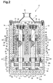
Fig. 2 is a cross-sectional view taken along line A-A of the vacuum pump ofFig. 1 ; -
Fig. 3 is an enlarged view showing a major portion of a proximal bearing portion and a distal bearing portion in the vacuum pump ofFig. 1 ; -
Fig. 4 is a cross-sectional view taken along line B-B of the vacuum pump ofFig. 1 ; and -
Fig. 5 is an enlarged sectional view of an oil feed pump in the vacuum pump ofFig. 1 . - One embodiment according to the present invention will now be described, with reference to
Figs. 1 to 5 . As shown inFig. 1 , a screw-type fluid machine according to the present embodiment is a screw-type vacuum pump 10 which is vertically placed and used for semiconductor manufacturing (hereinafter simply referred to as a "vacuum pump"). Thevacuum pump 10 has ahousing 14 having anupper housing member 11, arotor housing member 12, and alower housing member 13. Thehousing 14 forms the shell of thevacuum pump 10. - In detail, the
upper housing member 11 is connected to the upper end of therotor housing member 12, and thelower housing member 13 is connected to the lower end of therotor housing member 12. Asuction port 15 to draw in a compressive fluid is formed in theupper housing member 11 so as to communicate with the interior of thehousing 14. Thelower housing member 13 is provided with adischarge port 16 to discharge the compressive fluid. Thedischarge port 16 communicates with the interior of thehousing 14. Also, thelower housing member 13 is provided with anextension part 13a caused to extend sideways, and adrive motor 17 operating as a drive source is installed on theextension part 13a. Furthermore, agear case 18 to cover thelower housing member 13 including theextension part 13a from downward thereof is connected to thelower housing member 13. - As shown in
Fig. 2 , a screw-typemale rotor 21 and a screw-typefemale rotor 31, which are meshed with each other, are accommodated in thehousing 14. An operation chamber is formed by therotors housing 14. Themale rotor 21 has aninsertion hole 22 extending from thedischarge port 16 toward thesuction port 15 and anconnection hole 23, the diameter of which is smaller than that of theinsertion hole 22, extending upward from the upper end of theinsertion hole 22. Arotary shaft 25 passing through thelower housing member 13 is inserted into theconnection hole 23. Themale rotor 21 and therotary shaft 25 are connected to each other by using astop plate 26 and aconnection bolt 27. Accordingly, themale rotor 21 and therotary shaft 25 rotate integrally. Similarly, thefemale rotor 31 shown inFig. 2 is provided with aninsertion hole 32 and a connection hole 33, and is connected to arotary shaft 35 by using astop plate 36 and a connection bolt 37. Each of therespective rotors rotary shafts - The
lower housing member 13 has a pair ofcylindrical shaft retainers Fig. 2 , the proximal portions of theshaft retainers shaft retainers lower housing member 13 by fixingbolts 41. Theshaft retainer 28 is inserted into theinsertion hole 22 of themale rotor 21, and a slight space is formed between the outer circumferential surface of theshaft retainer 28 and the inner-circumferential surface of theinsertion hole 22. Theshaft retainer 38 is inserted into theinsertion hole 32 of thefemale rotor 31, and a slight space is also formed between the outer circumferential surface of theshaft retainer 38 and the inner circumferential surface of theinsertion hole 32. - A through
hole 29 extending in the axial direction is formed at the center of theshaft retainer 28, and therotary shaft 25 for themale rotor 21 is inserted into the throughhole 29. A pair of upper andlower bearing portions rotary shaft 25 and theshaft retainer 28. The bearingportions shaft retainer 28. In this embodiment, theupper bearing portion 42 is a distal bearing portion or a second bearing portion, and thelower roller bearing 43 is a proximal bearing portion or a first bearing portion. An upperlarge diameter hole 29a having a larger diameter than the diameter of the throughhole 29 is formed at the upper end portion (the second end portion) of theshaft retainer 28, continuous to the throughhole 29. Thedistal bearing portion 42 is disposed in the upperlarge diameter hole 29a. Also, the portion between thedistal bearing 42 and theproximal bearing 43 at therotary shaft 25 has a slightly larger diameter than that of the upper and lower parts of therotary shaft 25. As shown inFig. 3 , the portion of therotary shaft 25, the diameter of which changes, forms adistal step portion 25a and aproximal step portion 25b. - As shown in
Figs. 1 and2 , a sealingmember 30 is located between therotary shaft 25 and theshaft retainer 28 at a position above thedistal bearing portion 42. A lowerlarge diameter hole 29b having a larger diameter than that of the throughhole 29 is provided at the lower end portion (the first end portion) of theshaft retainer 28, continuous to the throughhole 29. Theproximal bearing portion 43 is disposed in the lowerlarge diameter hole 29b. - These bearing
portions rotary shaft 25 with respect to theshaft retainer 28. In the embodiment, each of thedistal bearing portion 42 and theproximal bearing portion 43 is structured by stacking two roller bearings each one being a single row. - A further detailed description will now be given of the
distal bearing portion 42. Thedistal bearing portion 42 is composed of a combination of twoangular ball bearings Fig. 3 , bothbearings large diameter hole 29a in a state of Duplex Back-to-back. The outer rings of bothbearings large diameter hole 29a and fixed to theshaft retainer 28. In addition, the inner rings of bothbearings rotary shaft 25. - The inner ring of the
angular ball bearing 42b is pressed against thedistal step portion 25a of therotary shaft 25, and the inner ring of theangular ball bearing 42a is pressed against the inner ring of theangular ball bearing 42b by anut 49a screwed in therotary shaft 25. As a result, the rolling elements of theangular ball bearings - On the other hand, as shown in
Fig. 3 , theangular ball bearings large diameter hole 29b at theproximal bearing portion 43 in a state of Duplex Back-to-back. The outer rings of thebearings large diameter hole 29b and are fixed to theshaft retainer 28. The inner ring of theangular ball bearing 43a is pressed against theproximal step portion 25b of therotary shaft 25, and the inner ring of theangular ball bearing 43b is pressed against the inner ring of theangular ball bearing 43a by anut 49b screwed in therotary shaft 25. Therefore, the rolling elements of theangular ball bearings - Since the
distal bearing portions 42 and theproximal bearing portions 43 are each composed of two angular ball bearings in the state of Duplex Back-to-back, therotary shaft 25 does not move in the axial direction and the radial direction with respect to theshaft retainer 28. That is, thedistal bearing portion 42 and theproximal bearing portion 43 are fixed in the axial direction by means of nuts 49a, 49b and thestep portions - These
angular ball bearings rotary shaft 25 and the inner circumferential surface of the throughhole 29 of theshaft retainer 28. The space forms a lubricant oil recovery passage 48 (hereinafter, simply referred to as an oil recovery passage 48). Theoil recovery passage 48 causeslubricant oil 62, which is a cooling medium, to be brought into contact with therotary shaft 25 and theshaft retainer 28, which are objects to be cooled down. Theoil recovery passage 48 is also a passage that supplieslubricant oil 62 to thegear case 18. - On the other hand, a
long conduit 44 extending along the axis of therotary shaft 25 is formed in therotary shaft 25. Thelong conduit 44 reaches the underside of thedistal bearing portion 42 from the lower end of therotary shaft 25. Ashort conduit 45 extending in the radial direction of therotary shaft 25 is formed in therotary shaft 25 below thedistal bearing portion 42. The upper end of thelong conduit 44 is located below thedistal bearing portion 42, and is connected to theshort conduit 45. Theshort conduit 45 is made open to the circumferential surface of therotary shaft 25 at a position below thedistal bearing portion 42 so as to communicate with theoil recovery passage 48. Thelong conduit 44 and theshort conduit 45 compose anoil feed passage 46 that supplieslubricant oil 62 to theoil recovery passage 48. Theoil feed passage 46 and theoil recovery passage 48 compose an oil circulation passage. - In the above, a description has been given of respective elements such as the
shaft retainer 28 at themale rotor 21,rotary shaft 25, bearingportions female rotor 31 basically have the same configuration as those at themale rotor 21. That is, as shown inFig. 2 , therotary shaft 35 is inserted into the throughhole 39 of theshaft retainer 38. Theshaft retainer 38 is provided with an upperlarge diameter hole 39a and a lowerlarge diameter hole 39b as in theshaft retainer 28. Adistal bearing portion 52 and aproximal bearing portion 53 are disposed in the upperlarge diameter hole 39a and the lowerlarge diameter hole 39b, respectively. The bearingportions rotary shaft 35 and theshaft retainer 38. - A
distal bearing portion 52 is composed of twoangular ball bearings distal bearing portion 42 of themale rotor 21, and is pushed down by a nut 59a. Further, a sealingmember 40 is disposed at a position above thedistal bearing portion 52. Theproximal bearing portion 53 is composed of twoangular ball bearings proximal bearing portion 43 of themale rotor 21, and is pushed upward by anut 59b. - In addition, an
oil feed passage 56 composed of along conduit 54 and ashort conduit 55 is formed in therotary shaft 35 of thefemale rotor 31. Further, a space that forms anoil recovery passage 58 is formed between therotary shaft 35 and theshaft retainer 38. The axial diameters of therotary shafts distal bearing portions proximal bearing portions - A detailed description will now be given of the
male rotor 21. As shown inFig. 4 , themale rotor 21 has fiveteeth 24, and theseteeth 24 are disposed equidistant in the circumferential direction of themale rotor 21. Also, theteeth 24 spirally extend from the upper end of themale rotor 21 to the lower end thereof. And, as shown inFig. 2 , theteeth 24 are formed so that the lead angle decreases from the upper end toward the lower end. - On the other hand,
tooth grooves 34 in thefemale rotor 31 are formed so as to correspond to theteeth 24 of themale rotor 21 as shown inFig. 4 , and the number of thetooth grooves 34 is six. That is, since the number of theteeth 24 of themale rotor 21 is fewer than the number of thetooth grooves 34 of thefemale rotor 31, the rotation speed of themale rotor 21 becomes faster than that of thefemale rotor 31 when bothrotors female rotor 31 becomes lower than that of themale rotor 21. Such screw-type rotors - As shown in
Figs. 1 and2 , therotary shaft 25 of themale rotor 21 extends so as to pass through thelower housing member 13, and the lower end of therotary shaft 25 is positioned in thegear case 18. The portion located in thegear case 18 of therotary shaft 25 is provided with asynchronous gear 47. On the other hand, therotary shaft 35 of thefemale rotor 31 extends so as to pass through thelower housing member 13 as well, and the lower end of therotary shaft 35 is positioned in thegear case 18. The portion located in thegear case 18 of therotary shaft 35 is provided with asynchronous gear 57. Both synchronous gears 47, 57 are meshed with each other. - As shown in
Fig. 1 , thesynchronous gear 47 at themale rotor 21 is meshed with anintermediate gear 50 secured in thegear case 18. Theintermediate gear 50 is meshed with adrive gear 20 attached to thedrive shaft 19 of thedrive motor 17 in thegear case 18. Anoil storage chamber 61 that composes an oil reservoir space is formed at the lower part of thegear case 18, andlubricant oil 62 is stored in theoil storage chamber 61. - A
cylindrical projection 63 is formed at the portion of thebottom plate 18a of thegear case 18, which is opposite to the lower end of therotary shaft 25. As shown inFig. 5 , theprojection 63 defines acircular hole 63a having a bottom. A trochoidaloil feed pump 70 operating as an oil feed portion is disposed in thecircular hole 63a. Theoil feed pump 70 includes anouter rotor 72 consisting of an inner-toothed gear and aninner rotor 71 consisting of an outer-toothed gear. Theinner rotor 71 is disposed inside theouter rotor 72. The outer circumferential surface of theouter rotor 72 is rotatably fitted to the inner circumferential surface of thecircular hole 63a. The lower end of therotary shaft 25 is fitted in and fixed in the throughhole 71a of theinner rotor 71. - The
inner rotor 71 is eccentric with respect to theouter rotor 72. When theinner rotor 71 rotates, theouter rotor 72 also rotates therewith. An opening at the upper end of thecylindrical projection 63 is blocked by anupper cover 73, and theupper cover 73 covers theinner rotor 71 and theouter rotor 72. In addition, theoil feed pump 70 has anoil suction portion 75 and anoil discharge portion 76. Theoil suction portion 75 communicates with theoil storage chamber 61. Theoil discharge portion 76 communicates with theoil feed passage 46 of therotary shaft 25 via aguide passage 77 formed on the bottom of thecircular hole 63a. - As the
rotary shaft 25 rotates,lubricant oil 62 stored in theoil storage chamber 61 is drawn in theoil feed pump 70 through theoil suction portion 75, in detail, drawn in a space between therotors rotors oil discharge portion 76. The oil is then fed from theoil discharge portion 76 to theoil feed passage 46 through theguide passage 77. - On the other hand, as shown in
Fig. 2 , acylindrical projection 64 is formed at the portion of thebottom plate portion 18a of thegear case 18, which is opposite to the lower end of therotary shaft 35. Theprojection 64 defines thecircular hole 64a having a bottom. A trochoidaloil feed pump 80 operating as an oil feed device is disposed in thecircular hole 64a. Although the structure of theoil feed pump 80 is not illustrated in detail, the structure is equivalent to theoil feed pump 70. That is, theoil feed pump 80 includes aninner rotor 81 and anouter rotor 82. The outer circumferential surface of theouter rotor 82 is rotatably fitted to the inner circumferential surface of thecircular hole 64a, and theinner rotor 81 is linked with therotary shaft 35. Theinner rotor 81 and theouter rotor 82 are covered by anupper cover 83. Also, although not illustrated, theoil feed pump 80 has an oil suction portion communicating with theoil storage chamber 61 and an oil discharge portion communicating with theoil feed passage 56 through aguide passage 87. When theinner rotor 81 rotates together with therotary shaft 35, theouter rotor 82 rotates, accordingly, and thelubricant oil 62 in theoil storage chamber 61 is fed to theoil feed passage 56 through the oil suction portion, a space between bothrotors guide passage 87. - In addition, the
vacuum pump 10 according to the present embodiment has a configuration to cool thelubricant oil 62 stored in thegear case 18. That is, a plurality of coolingwater passages 88 through which cooling water operating as a cooling fluid passes are formed in thebottom plate portion 18a of thegear case 18. The coolingwater passages 88 extend so as to pass through thebottom plate 18a. Since cooling water is caused to pass through the coolingwater passage 88, thelubricant oil 62 stored in thegear case 18 is then cooled. The coolingwater passages 88 function as a cooling portion to cool down thelubricant oil 62 by using the cooling fluid. - As shown in
Fig. 1 , the upstream part of the coolingwater passage 88 is connected to anupstream pipe 89 provided with asolenoid valve 91 as a flow rate changing portion, and the downstream part of the coolingwater passage 88 is connected to adownstream pipe 90. Thesolenoid valve 91 is controlled so as to open and close theupstream pipe 89 by acontroller 92 operating as a control portion. Thecontroller 92 is connected to atemperature sensor 93 that directly measures the temperature of thelubricant oil 62 in thegear case 18. Thetemperature sensor 93 is disposed in thegear case 18, that is, in theoil storage chamber 61. Thecontroller 92 controls thesolenoid valve 91 based on detection signals from thetemperature sensor 93 so that the temperature of thelubricant oil 62 in thegear case 18 is maintained to be constant. - Next, a description is given of operations of the
vacuum pump 10 according to the embodiment. When thedrive motor 17 is rotated, rotation of thedrive motor 17 is transmitted to thesynchronous gear 47 of themale rotor 21 via thedrive gear 20 and theintermediate gear 50. Thus, the synchronous gears 47, 57 rotate in synchronization with each other, and therotors rotary shafts rotors teeth 24 of themale rotor 21 are engaged with thetooth grooves 34 of thefemale rotor 31, a compressive fluid is drawn in the operation chamber through thesuction port 15. The compressive fluid drawn in the operation chamber is conveyed to thedischarge port 16 while being compressed by therotors discharge port 16. If thesuction port 15 is connected to a closed space such as a chamber or a vessel, the closed space can be made in a vacuum state. - When the
vacuum pump 10 is operating, therotary shafts rotary shaft lubricant oil 62 stored in theoil storage chamber 61 through respective oil suction portions and discharge the same through the respective oil discharge portions. Dischargedlubricant oil 62 flows into the lower ends of thelong conduits rotary shafts guide passages distal bearing portions short conduits - When the
lubricant oil 62 that has reached the underside of thedistal bearing portions oil recovery passages rotary shafts shaft retainers rotary shafts shaft retainers rotary shafts shaft retainers lubricant oil 62 is recovered in theoil storage chamber 61 in thegear case 18 after having cooled therotary shafts shaft retainers lubricant oil 62 is conveyed from theoil storage chamber 61 to theoil feed pump lubricant oil 62 lubricates the synchronous gears 47, 57 via the synchronous gears 47, 57 on the way of being recovered into theoil storage chamber 61. - Also, the
lubricant oil 62 stored in thegear case 18 is cooled by cooling water passing through the coolingwater passage 88. That is, in the present embodiment, thelubricant oil 62 is cooled by using cooling water so that the temperature of thelubricant oil 62 supplied for cooling by actions of the oil feed pumps 70, 80 is kept constant. In detail, thecontroller 92 monitors the temperature of thelubricant oil 62 by means of thetemperature sensor 93, and controls thesolenoid valve 91 so that the temperature of thelubricant oil 62 is maintained at a preset cooling temperature. Thecontroller 92 opens and closes thesolenoid valve 91 in accordance with the temperature of thelubricant oil 62, which is detected by thetemperature sensor 93, and adjusts the flow of the cooling water in the coolingwater passage 88. That is, thecontroller 92 opens thesolenoid valve 91 when the temperature of thelubricant oil 62 is likely to rise, and prevents the temperature rise of thelubricant oil 62 in thegear case 18 by causing cooling water to flow through the coolingwater passages 88. In addition, thecontroller 92 closes thesolenoid valve 91 when the temperature of thelubricant oil 62 is likely to lower, and does not cool thelubricant oil 62 by cooling water by not causing the cooling water to flow through the coolingwater passages 88. In this case, the temperature of thelubricant oil 62 stored in theoil storage chamber 61 is prevented from being lowered by the heat of thelubricant oil 62 stored in theoil storage chamber 61. - By causing the
lubricant oil 62, which is kept at a constant temperature, to pass through theoil recovery passages rotary shafts shaft retainers rotary shafts rotary shafts bearings - The
vacuum pump 10 according to the present embodiment has the following advantages. - (1) The
controller 92 controls thesolenoid valve 91 based on a detection result of the temperature oflubricant oil 62 by thetemperature sensor 93. Therefore, the flow rate of cooling water is adjusted so that thelubricant oil 62 stored in theoil storage chamber 61 is kept at a constant temperature. By causing • thelubricant oil 62, the temperature of which is kept constant, to pass through theoil recovery passages rotary shafts shaft retainers rotary shaft 25 and theshaft retainer 28 and to prevent a difference in temperature from occurring between therotary shaft 35 and theshaft retainer 38. - (2) The
angular ball bearings rotary shafts shaft retainers rotary shafts shaft retainers rotary shafts shaft retainers bearings - (3) Since load is prevented from being applied to the
respective bearings vacuum pump 10 is reduced. - (4) Since load is prevented from being applied to the
respective bearings distal bearing portions proximal bearing portions portions rotary shafts - (5) Since the
bearings rotary shafts shaft retainers rotary shafts vacuum pump 10 regardless of the rotation speed of therotary shafts - (6) Since
lubricant oil 62 is supplied into theoil recovery passages distal bearing portions lubricant oil 62 supplied to theoil recovery passages distal bearing portions lubricant oil 62 in theoil recovery passages - (7) Since the
lubricant oil 62 passes through the synchronous gears 47, 57 on the way of being recovered into theoil storage chamber 61, the synchronous gears 47, 57 can also be lubricated. - The present invention is not to be limited to the foregoing embodiment, but may be modified as follows within the scope of the invention.
- A gear pump may be adopted for the oil feed pumps 70, 80 instead of a trochoidal pump.
- The lead angle of the teeth of the male rotor and the tooth grooves of the female rotor may be fixed.
- In the above-described embodiment, the respective bearing portions are composed of two angular ball bearings in a state of Duplex Back-to-back. However, these may be composed by a combination thereof in a state of Duplex Face-to-face or by a combination thereof in a state of Duplex Tandem. Further, the respective bearing portions are not limited to angular ball bearings, but may be composed of ordinal deep groove type roller bearings. Still further, the number of the roller bearings is not specifically limited, and the respective bearing portions may be composed of three or more roller bearings. Also, in order to prevent horizontal sway of the rotary shafts with respect to the shaft retainers, it is preferable that angular ball bearings be combined at the backs thereof.
- A thermostat may be used instead of an open/close
type solenoid valve 91, or a flow rate control valve which is capable of adjusting the opening degree based on proportional control may be adopted. - The
short conduits distal bearing portions distal bearing portions distal bearing portions - The
shaft retainer 28 of themale rotor 21 and theshaft retainer 38 of thefemale rotor 31 may be composed of completely separate members. In this case, it becomes easy to manufacture theshaft retainers - The screw-type fluid machine according to the present invention is not limited to a screw-type vacuum pump, but may be applicable to a screw-type compressor.
Claims (6)
- A screw-type fluid machine, comprising:a housing;a pair of screw-type rotors accommodated in the housing and meshed with each other;a pair of rotary shafts each coaxially coupled to one of the rotors, each rotary shaft having an end portion protruding from the housing;a pair of cylindrical shaft retainers extending in the housing, each shaft retainer having a first end portion and a second end portion, and having a through hole into which one of the rotary shafts is inserted;first bearing portions each mounted in the through hole at one of the first end portions;second bearing portions each mounted in the through hole at one of the second end portions, each pair of the first and second bearing portions rotatably supporting the corresponding rotary shaft with respect to the shaft retainer, and each pair of the first and second bearing portions being fixed in the axial direction with respect to the corresponding rotary shaft and the corresponding shaft retainer;synchronous gears each provided at the end portion of one of the rotary shafts protruding from the housing;a gear case in which the synchronous gears are accommodated, the gear case defining an oil storage space capable of storing lubricant oil;a cooling portion for cooling the lubricant oil by using a cooling fluid;a flow rate changing portion for controlling the flow rate of the cooling fluid;a temperature sensor provided in the oil storage space, which detects the temperature of the lubricant oil; anda control portion for controlling the flow rate changing portion in accordance with the temperature detected by the temperature sensor so that the temperature of the lubricant oil in the oil storage space is kept constant.
- The screw-type fluid machine according to claim 1, wherein the first and second bearing portions are each composed of a combination of at least two roller bearings.
- The screw-type fluid machine according to claim 2, wherein the roller bearings include angular ball bearings.
- The screw-type fluid machine according to any one of claims 1 to 3, wherein the cooling portion includes a cooling water passage extending in the gear case so as to permit passage of the cooling fluid.
- The screw-type fluid machine according to any one of claims 1 to 4, further including oil feed portions each driven by one of the rotary shafts so that the shaft retainers and the rotary shafts are cooled by using lubricant oil in the oil storage space.
- The screw-type fluid machine according to claim 5, wherein a space is provided between the inner circumferential surface of each shaft retainer and the outer circumferential surface of the corresponding rotary shaft, an oil feed passage having an inlet opening to the end portion of the rotary shaft and an outlet communicating with the space is formed at each rotary shaft, wherein the oil feed portion is a pump provided at the end portion of each of the rotary shafts, and the pump supplies lubricant oil existing in the oil storage space to the inlet of the oil feed passage of the corresponding rotary shaft.
Applications Claiming Priority (2)
| Application Number | Priority Date | Filing Date | Title |
|---|---|---|---|
| JP2005372225A JP2007170341A (en) | 2005-12-26 | 2005-12-26 | Screw type fluid machine |
| PCT/JP2006/325864 WO2007074807A1 (en) | 2005-12-26 | 2006-12-26 | Screw-type fluid machine |
Publications (1)
| Publication Number | Publication Date |
|---|---|
| EP1967734A1 true EP1967734A1 (en) | 2008-09-10 |
Family
ID=38218027
Family Applications (1)
| Application Number | Title | Priority Date | Filing Date |
|---|---|---|---|
| EP06843248A Withdrawn EP1967734A1 (en) | 2005-12-26 | 2006-12-26 | Screw-type fluid machine |
Country Status (4)
| Country | Link |
|---|---|
| US (1) | US20100233006A1 (en) |
| EP (1) | EP1967734A1 (en) |
| JP (1) | JP2007170341A (en) |
| WO (1) | WO2007074807A1 (en) |
Cited By (2)
| Publication number | Priority date | Publication date | Assignee | Title |
|---|---|---|---|---|
| EP2957772A3 (en) * | 2014-06-02 | 2016-01-20 | Pfeiffer Vacuum GmbH | Vacuum pump |
| US10107289B2 (en) | 2011-05-05 | 2018-10-23 | Howden Compressors Limited | Bearing insert having flattened portion and fluid machine having the same |
Families Citing this family (7)
| Publication number | Priority date | Publication date | Assignee | Title |
|---|---|---|---|---|
| KR101065288B1 (en) * | 2008-09-11 | 2011-09-16 | 주식회사 에스백 | Cooled Vacuum Pump |
| KR101406474B1 (en) | 2012-11-08 | 2014-06-12 | 주식회사 포스코 | Metal pump of plating facilities |
| EP2935919A1 (en) * | 2012-12-20 | 2015-10-28 | Aktiebolaget SKF | Machine arrangement |
| US10495090B2 (en) * | 2015-08-27 | 2019-12-03 | Ingersoll-Rand Company | Rotor for a compressor system having internal coolant manifold |
| DE102016011443A1 (en) * | 2016-09-21 | 2018-03-22 | Knorr-Bremse Systeme für Nutzfahrzeuge GmbH | Screw compressor for a commercial vehicle |
| DE102019205258A1 (en) * | 2019-04-11 | 2020-10-15 | Gardner Denver Nash Llc | Screw compressors |
| CN115853780B (en) * | 2022-11-10 | 2023-09-12 | 江阴华西节能技术有限公司 | Variable pitch screw vacuum pump |
Family Cites Families (15)
| Publication number | Priority date | Publication date | Assignee | Title |
|---|---|---|---|---|
| US4780061A (en) * | 1987-08-06 | 1988-10-25 | American Standard Inc. | Screw compressor with integral oil cooling |
| FR2637655B1 (en) * | 1988-10-07 | 1994-01-28 | Alcatel Cit | SCREW PUMP TYPE ROTARY MACHINE |
| JPH04314991A (en) | 1991-02-01 | 1992-11-06 | Hitachi Ltd | Lubricating oil cooling structure of screw vacuum pump |
| JPH08100779A (en) * | 1994-10-04 | 1996-04-16 | Matsushita Electric Ind Co Ltd | Vacuum pump |
| KR100424386B1 (en) * | 1995-06-21 | 2004-07-15 | 스털링 인더스트리 컨설트 게엠베하 | Multi-stage Screw-Spindle Compressors |
| JPH10141260A (en) * | 1996-11-12 | 1998-05-26 | Dia Shinku Kk | Oil circulating-type mechanical pump |
| JP3495899B2 (en) * | 1997-12-24 | 2004-02-09 | 株式会社神戸製鋼所 | Screw refrigerator |
| DE69929749T2 (en) * | 1998-06-17 | 2006-08-24 | The Boc Group Plc, Windlesham | screw pump |
| DE19963172A1 (en) * | 1999-12-27 | 2001-06-28 | Leybold Vakuum Gmbh | Screw-type vacuum pump has shaft-mounted rotors each with central hollow chamber in which are located built-in components rotating with rotor and forming relatively narrow annular gap through which flows cooling medium |
| US6793466B2 (en) * | 2000-10-03 | 2004-09-21 | Ebara Corporation | Vacuum pump |
| JP4056691B2 (en) * | 2000-11-02 | 2008-03-05 | 株式会社神戸製鋼所 | Bearing cooling method and bearing cooling device |
| DE10156179A1 (en) * | 2001-11-15 | 2003-05-28 | Leybold Vakuum Gmbh | Cooling a screw vacuum pump |
| DE20302989U1 (en) * | 2003-02-24 | 2004-07-08 | Werner Rietschle Gmbh + Co. Kg | Rotary pump |
| JP4558349B2 (en) * | 2004-03-02 | 2010-10-06 | 財団法人国際科学振興財団 | Vacuum pump |
| JP2007126993A (en) * | 2005-11-01 | 2007-05-24 | Toyota Industries Corp | Vacuum pump |
-
2005
- 2005-12-26 JP JP2005372225A patent/JP2007170341A/en not_active Withdrawn
-
2006
- 2006-12-26 EP EP06843248A patent/EP1967734A1/en not_active Withdrawn
- 2006-12-26 WO PCT/JP2006/325864 patent/WO2007074807A1/en not_active Ceased
- 2006-12-26 US US12/159,186 patent/US20100233006A1/en not_active Abandoned
Non-Patent Citations (1)
| Title |
|---|
| See references of WO2007074807A1 * |
Cited By (4)
| Publication number | Priority date | Publication date | Assignee | Title |
|---|---|---|---|---|
| US10107289B2 (en) | 2011-05-05 | 2018-10-23 | Howden Compressors Limited | Bearing insert having flattened portion and fluid machine having the same |
| EP2712410B1 (en) * | 2011-05-05 | 2019-03-13 | Howden Compressors Limited | Fluid machine |
| EP2957772A3 (en) * | 2014-06-02 | 2016-01-20 | Pfeiffer Vacuum GmbH | Vacuum pump |
| EP2957772B2 (en) † | 2014-06-02 | 2022-12-14 | Pfeiffer Vacuum GmbH | Vacuum pump |
Also Published As
| Publication number | Publication date |
|---|---|
| WO2007074807A1 (en) | 2007-07-05 |
| US20100233006A1 (en) | 2010-09-16 |
| JP2007170341A (en) | 2007-07-05 |
Similar Documents
| Publication | Publication Date | Title |
|---|---|---|
| US5256042A (en) | Bearing and lubrication system for a scroll fluid device | |
| CN100465452C (en) | Vacuum pump | |
| JP2003518589A (en) | Screw type vacuum pump with cooling medium circuit | |
| KR20190068013A (en) | Vehicle motor drive apparatus and method of cooling and lubricating the same | |
| US20100233006A1 (en) | Screw-type fluid machine | |
| CN204646671U (en) | scroll compressor | |
| WO2016173319A1 (en) | Scroll compressor | |
| JP4564971B2 (en) | Oil-free screw compressor | |
| US20120183391A1 (en) | Turbomachinery with integrated pump | |
| JP4838770B2 (en) | Turbo compressor and turbo refrigerator | |
| CN103688059B (en) | Direct Cooled Screw Vacuum Pumps | |
| JP2004092878A (en) | Slide bearing | |
| CN215805190U (en) | Compressor and air conditioner with same | |
| JP5078680B2 (en) | Turbo compressor and turbo refrigerator | |
| JP2001041162A (en) | Positive displacement fluid machinery | |
| KR102157980B1 (en) | Single screw compressors and compression systems to prevent leakage of lubricants through half-loaded compressed air exhaust | |
| CN105351203A (en) | Compressor | |
| JP5181534B2 (en) | Scroll compressor | |
| JP3931168B2 (en) | Oil-free screw compressor | |
| JPH10281089A (en) | Vacuum pump | |
| JP2008121479A (en) | Hermetic screw compressor | |
| JP7263554B2 (en) | scroll compressor | |
| CN210565070U (en) | Compression mechanism of scroll compressor and scroll compressor | |
| JP3163284U (en) | Rotating equipment | |
| CN221120318U (en) | Scroll compressor having a rotor with a rotor shaft having a rotor shaft with a |
Legal Events
| Date | Code | Title | Description |
|---|---|---|---|
| PUAI | Public reference made under article 153(3) epc to a published international application that has entered the european phase |
Free format text: ORIGINAL CODE: 0009012 |
|
| 17P | Request for examination filed |
Effective date: 20080409 |
|
| AK | Designated contracting states |
Kind code of ref document: A1 Designated state(s): DE GB |
|
| RBV | Designated contracting states (corrected) |
Designated state(s): DE GB |
|
| STAA | Information on the status of an ep patent application or granted ep patent |
Free format text: STATUS: THE APPLICATION HAS BEEN WITHDRAWN |
|
| 18W | Application withdrawn |
Effective date: 20110307 |