EP1967330A2 - Vielzweckhandwerkzeug mit drehbarem Griff - Google Patents
Vielzweckhandwerkzeug mit drehbarem Griff Download PDFInfo
- Publication number
- EP1967330A2 EP1967330A2 EP08102261A EP08102261A EP1967330A2 EP 1967330 A2 EP1967330 A2 EP 1967330A2 EP 08102261 A EP08102261 A EP 08102261A EP 08102261 A EP08102261 A EP 08102261A EP 1967330 A2 EP1967330 A2 EP 1967330A2
- Authority
- EP
- European Patent Office
- Prior art keywords
- handle
- tool
- shaft
- locking
- latch release
- Prior art date
- Legal status (The legal status is an assumption and is not a legal conclusion. Google has not performed a legal analysis and makes no representation as to the accuracy of the status listed.)
- Withdrawn
Links
Images


Classifications
-
- B—PERFORMING OPERATIONS; TRANSPORTING
- B25—HAND TOOLS; PORTABLE POWER-DRIVEN TOOLS; MANIPULATORS
- B25F—COMBINATION OR MULTI-PURPOSE TOOLS NOT OTHERWISE PROVIDED FOR; DETAILS OR COMPONENTS OF PORTABLE POWER-DRIVEN TOOLS NOT PARTICULARLY RELATED TO THE OPERATIONS PERFORMED AND NOT OTHERWISE PROVIDED FOR
- B25F1/00—Combination or multi-purpose hand tools
- B25F1/003—Combination or multi-purpose hand tools of pliers'-, scissors'- or wrench-type with at least one movable jaw
-
- B—PERFORMING OPERATIONS; TRANSPORTING
- B25—HAND TOOLS; PORTABLE POWER-DRIVEN TOOLS; MANIPULATORS
- B25F—COMBINATION OR MULTI-PURPOSE TOOLS NOT OTHERWISE PROVIDED FOR; DETAILS OR COMPONENTS OF PORTABLE POWER-DRIVEN TOOLS NOT PARTICULARLY RELATED TO THE OPERATIONS PERFORMED AND NOT OTHERWISE PROVIDED FOR
- B25F1/00—Combination or multi-purpose hand tools
- B25F1/02—Combination or multi-purpose hand tools with interchangeable or adjustable tool elements
- B25F1/04—Combination or multi-purpose hand tools with interchangeable or adjustable tool elements wherein the elements are brought into working positions by a pivoting or sliding movement
-
- B—PERFORMING OPERATIONS; TRANSPORTING
- B25—HAND TOOLS; PORTABLE POWER-DRIVEN TOOLS; MANIPULATORS
- B25G—HANDLES FOR HAND IMPLEMENTS
- B25G1/00—Handle constructions
- B25G1/10—Handle constructions characterised by material or shape
- B25G1/102—Handle constructions characterised by material or shape the shape being specially adapted to facilitate handling or improve grip
Definitions
- This invention relates to multipurpose hand tools and particularly to a tool whose handle provides a comfortable grip during use and also provides storage for folding tool blades or tool bits.
- Multipurpose hand tools often provide for storage of folding blades within a cavity defined within a handle.
- a two-handled hand tool such as pliers or shears
- orientation of the handles so as to present a comfortable outer face to be gripped when the handles are squeezed toward each other has required the handles of many such tools to be spread apart from each other in order for folding blades to be moved between their folded and their extended positions.
- a two-handled tool includes one or more sharp-edged blades, as in a pruning shear, swinging the handles apart from each other may expose a sharp edge of a working portion of the tool where it may be damaged or may cause injury to an inattentive user of the tool.
- a multipurpose hand tool including a handle capable of being gripped comfortably during use of the tool and which can nevertheless safely and readily provide access to folded tool blades and bits without exposing sharp-edged blades of the tool unnecessarily.
- the present application discloses a hand tool which provides an answer to the aforementioned shortcomings of previously known tools, as defined by the claims which form a part of the disclosure herein.
- a pair of handles are arranged to be gripped comfortably by one hand to operate the pruning shear.
- One handle of the pair includes a storage cavity to hold one or more folding blades or tool bits attached pivotably to an outer end of that handle, and that handle is mounted so as to be able to pivot around a longitudinal axis to present the folded blades or tool bits where they are available to be extended without moving the handles apart from each other, so that the blades of the pruning shear can remain latched closed while knife blades are folded into or extended from the handle.
- a rotary coupling in which a conveniently operable lock normally holds a handle securely in a selected position of rotation about an axis.
- a latch mechanism for holding a selected one of the folding blades or tool bits in an extended position relative to the handle includes latch release grips available conveniently at the sides of the handle.
- a guard extends from a central body portion of the tool and along a portion of the handle, preventing a folded blade from being unfolded from storage in the handles during use of the pruning shears.
- FIG. 1 is a right side elevational view of a multipurpose hand tool including a bypass pruner and embodying the present invention, with the pruner latched in a closed position and with a top, or rear, handle in a position providing for a comfortable grip during use of the pruner.
- FIG. 2 is a right side elevational view of a portion of the hand tool shown in FIG. 1 , with the pruner unlatched and the handles and pruner blades opened.
- FIG. 3 is a left side elevational view of the hand tool shown in FIGS. 1 and 2 , with the handles and blades latched in a closed position as in FIG. 1 .
- FIG. 4 is a top plan view of the hand tool shown in FIG. 3 .
- FIG. 5 is a top plan view of a portion of the hand tool shown in FIG. 3 , with the top, or rear, handle rotated with respect to the rest of the tool to a position opposite that shown in FIGS. 3 and 4 .
- FIG. 6 is a left side elevational view of the portion of a tool shown in FIG. 5 , with the top or rear handle in the position shown in FIG. 5 .
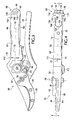
- FIG. 7 is a sectional view of a portion of the hand tool, taken along line 7-7 of FIG. 4 , at an enlarged scale.
- FIG. 8 is a sectional view of a portion of the hand tool, taken in the direction of the line 7-7 in FIG. 4 , showing the top, or rear, handle rotated to the position in which it is shown in FIGS. 5 and 6 , and showing a portion of a knife blade that is latched in an extended position with respect to the handle.
- FIG. 9 is a sectional view taken along line 9-9 of FIG. 7 , showing the locking mechanism of the rotary coupling between the handle and the main body of the hand tool.
- FIG. 10 is a sectional view similar to that in FIG. 9 , showing the push-button depressed and the rotary coupling in an unlocked condition.
- FIG. 11 is a partially cutaway top plan view of an outer end portion of the top, or rear, handle of the tool, at an enlarged scale.
- FIG. 12 is a sectional view taken along line 12-12 of FIG. 11 .
- FIG. 13 is view similar to FIG. 12 showing the latch release lever moved to a blade-releasing position.
- a multipurpose hand tool 20 that includes a pruning shear is shown in FIG. 1 with the pruning shear in a closed and latched condition and in FIG. 2 with the pruning shear in an unlatched, open condition.
- the tool 20 includes a first or left side main portion 21 including a first, top, or rear, handle 22, and a second or right side main portion 23 including a more slender second handle 24.
- the left and right side main portions 21 and 23 are interconnected with each other by a main tool pivot joint having an axis 26.
- a first working member in the form of a support jaw 28 included in the left side main portion 21 has a base 30, shown best in FIG. 3 , that extends from a central body portion 32 to which the first handle 22 is attached.
- a second working member in the form of a replaceable sharp-edged by-pass cutter blade 34 has a base 36 mounted detachably, as by rivets 40, on a blade carrier portion 42 of the right side main portion 23.
- the base of the blade carrier portion 42 extends from a hub portion 44 of the right side main portion 23 that is connected to the central body portion 32 of the left side main portion 21 by the main tool pivot joint.
- the multipurpose tool 20 could instead incorporate other types of working members such as a cutting blade and an anvil of another type of pruner, or various shears or pliers for other purposes.
- a conventional spring 46 is mounted between the central body portion 32 and a base 48 of the second handle 24 and urges the handles 22 and 24 apart from each other toward the position shown in FIG. 2 in order to open the sharp-edged by-pass blade 34 apart from the support jaw 28.
- a safety latch to keep the pruning shear safely closed when it is not in use may include a dog 50 located in a channel 52 defined in the central body portion 32 and carried on a cross-pin extending through a slot 56 in the central body portion 32. The dog 50 can be moved along the slot 56 by either of a pair ofknobs 58 and 60 located on opposite ends of the cross-pin and on opposite sides of the central body portion 32.
- the dog 50 can be extended into a receptacle in the form of a pocket 62 defined in the hub portion 44, when the pruning shear is closed with the handles 22 and 24 located close to each other so that the blade 34 is alongside the support jaw 28 as shown in FIG. 1 .
- the safety latch must be released by moving the dog 50 rearwardly in the channel 52 to the position shown in FIG. 2 , retracting the dog 50 from the pocket 62, in order for the handles 22 and 24 of tool 20 to be separated to the position shown in FIG. 2 by pivoting with respect to each other about the axis 26.
- the central body portion 32, the body of the handle 22, and the handle 24 may be made of a light yet suitably strong material such as a die-cast or injection molded aluminum alloy.
- the bases 36 and 30 may be machined as necessary to receive, respectively, the sharpened blade 34 and a working portion 64 of the support jaw 28, both of which may be made of a more durable and easily sharpened material such as a carbon steel or stainless steel.
- FIGS. 1 through 4 the handle 22 is shown in a normal position with respect to the central body portion 32 to provide a comfortable grip during use of the pruning shear aspect of the multipurpose tool 20.
- Smooth side faces 66 and a smooth back face 68 of the handle 22 are interconnected with each other along smoothly curved radiused edges, so that the handle 22 in that position presents a comfortable rounded shape with ample surface area to be gripped by a user's hand in operating the pruning shears of the multipurpose hand tool 20.
- a first, or front end 70 of the handle 22 is joined with the central body portion 32 by a rotary coupling permitting the handle 22 to be rotated about an axis 72 with respect to the central body portion 32 to the position shown in FIGS. 5 and 6 .
- the axis 72 may be more or less parallel with a longitudinal axis 73 of the handle 22.
- the handle 22 has a body defining a storage cavity 74 in a channel defined by a pair of side walls 76 and 78 and a back 80.
- several folding tool elements including a knife blade 82, a screwdriver 84, a chisel 86, and a saw 88 may all be stored in a folded position in the cavity 74, with a base portion 94 of each mounted on a tool pivot shaft 90 extending transversely through the handle 22 at its outer end 91.
- the pivot shaft 90 may be, for example, a tubular screw extending through the side walls 76 and 78 and a base portion of each of the tool blades 82, 84, 86, and 88.
- a guard, or keeper 92 protrudes rearwardly from the central body portion 32 at the front end 70 of the handle 22 and extends between the handle 22 and the handle 24, where it prevents the knife blade 82, chisel 86, and saw 88 from being opened from their folded positions within the storage cavity 74 of the handle 22, when the handle 22 is in its normal position of rotation with respect to the central body portion 32, as shown in FIGS. 1-4 .
- the guard 92 no longer obstructs any of the folding tool elements, and a selected one, such as the knife blade 82, for example, may be rotated about the tool pivot shaft 90 to an extended position, as shown in FIG. 6 .
- each folding tool blade element defines a respective latch engagement notch 96, as may be seen in FIG. 5 .
- a blade locking latch 98 includes a locking bar 100 carried on an outer end of a latch release lever 102, shown in FIG. 4 , to engage the latch engagement notch 96 in a selected one of the tool blades 82, 84, 86, and 88, to hold the selected folding tool blade or bit in an extended position, as will be explained in greater detail below.
- the handle 22 is held securely in a selected position of rotation about the axis 72 with respect to the central body portion 32, either in the position shown in FIGS. 1-4 or the position shown in FIGS. 5 and 6 , by a locking rotary coupling 110 that controls rotation of the handle 22 about the axis 72.
- a push-button 112 is located on the left-hand side of the central body portion 32, as shown in FIGS. 3 and 4 , and is used to control operation of the rotary coupling 110.
- the locking rotary coupling 110 includes a rotating body or spindle 113 including a shaft 114 of suitably strong and durable material such as steel.
- a mounting base 116 in the form of a head extending radially from a first end of the shaft 114 is shaped, as may be seen in FIGS. 5 , 7, and 8 , to fit matingly against inner surfaces of the side walls 76 and 78 and back 80 within the storage cavity 74, at the front end 70 of the handle 22, preventing the spindle 113 from rotating with respect to the handle 22.
- the mounting base could be of another form and could be otherwise connected to the handle 22, so long as a secure, strong, and rigid connection is provided, and the entire spindle member 113 could be formed integrally with the handle 22 using appropriately strong materials.
- the shaft 114 extends forward through a shaft receiving bore 118 in the front end 70, and into a corresponding bore 120, defined in the central body portion 22, that acts as a radial bearing to support a journal portion 122 of the shaft 114. It will be understood that a bushing (not shown) of a desired material defining a part of the bore 120 could also be fitted as a bearing within the central body portion 32, if desired, to support the journal portion 122 of the shaft 114. Since the axis of rotation 72 is defined by the shaft 114 the orientation of the shaft receiving bore 118 in the handle 22 establishes the path along which the handle 22 can rotate, and so the bore 118 will usually be generally parallel with a longitudinal axis 73 of the handle 22.
- annular groove 124 is formed around the circumference of the shaft 114, and a retainer screw 126 mated in a threaded bore extending transversely through the central body portion 32 of the tool also passes along and protrudes into the annular groove 124 as shown in FIGS. 7 and 8 , keeping the spindle 113 and handle 22 from moving longitudinally away from the central body portion 32.
- retainers could also be used to keep the shaft 114 from moving axially from a desired position.
- a spring clip engaging the annual groove 124 could be held in appropriately located slots (not shown) in the central body portion 32, but the retainer screw 126 provides a secure fastening which is closed against intrusion of dirt.
- a spring washer 128 may be mounted on the shaft 114 between the handle 22 and the central body portion 32, as shown in FIGS. 7 and 8 .
- a pair of engagement, or locating, faces 130 and 132 are provided on the shaft 114 and may take the form of flats formed on opposite sides of the shaft 114. While the locating faces 130 and 132 are shown in the embodiment of the tool disclosed herein as being flats located near the distal end of the shaft 114, it will be understood that they could instead be located at a different position along the length of the shaft 114, so long as an appropriate location is available for the push-button 112.
- a locking body 136 Attached to the push-button 112 and extending transversely through the central body portion 32 is a locking body 136 in the form of a transversely extending bolt held slidably in a transverse bore 138 which tangentially intersects the shaft receiving bore 120.
- a compression spring 140 surrounds the locking body 136 adjacent the inner face of the push-button 112 and urges the locking body 136 toward the left side of the central body portion 32, until a locking ramp or wedge surface 142 comes to bear against one of the locating faces 130 or 132 as shown in FIG. 9 and thereby prevents rotation of the shaft 114 so long as the locking ramp or wedge surface 142 remains engaged with the locating face 130 or 132.
- the locking ramp surface 142 may be oriented at an angle 144 to a plane parallel with the longitudinal axes of the locking body 136 and the shaft 114, to provide a self-tightening camming action of the locking body 136 with respect to one of the locating faces 130 and 132.
- An acceptable angle 144 may be within the range of zero to nine degrees, and an angle 144 of about seven degrees has been found to be particularly suitable.
- the locating faces 130 and 132 are accordingly located at suitable angles with respect to the orientation of the mounting base 116 so that the handle 22 will be held in a desired position of rotation about the axis 72 when the surface of the locking ramp 142 is mated against either of the locating faces 130 and 132.
- a channel 146 defined in the locking body 136 provides sufficient clearance between the locking ramp 142 and the push-button 112 so that when the push-button 112 is fully depressed into a receptacle 148 defined in the central body portion 32 the shaft 114 and thus the handle 22 can be rotated freely between the positions defined by the locating faces 130 and 132 and shown respectively in FIGS. 3 and 6 . Additionally, when the retainer screw 126 is removed and the push-button 112 is fully depressed as shown in FIG. 10 the channel 146 also provides clearance for the shaft 114 to be inserted into or removed from the bore 120 in the central body portion 32 of the tool 20.
- the push-button 112 When the push-button 112 is depressed fully and the top, or rear handle 22 has been rotated several degrees about the axis 72, the push-button 112 can be released and the handle can continue to be rotated the rest of the way to one of the available positions.
- the spring 140 will then move the locking body 136 to cause the locking ramp 142 to engage the respective one of the locating faces 130,132 to securely hold the handle 22 in the selected position of rotation about the axis 72. While the two discrete defined positions established by the locating faces 130, 132 are sufficient for the handle 22 of the tool 20, it is conceivable that 3 or even 4 or more locating faces to establish a like number of discrete positions of rotation of a handle might be desired for a particular hand tool.
- the latch release lever 102 is mounted in an opening 154 in the back 80 of the handle 22.
- the locking bar 100 engages not only the latch engagement notch 96 in the base portion 94 of a selected blade such as the knife blade 82 shown extended in FIG. 8 , but in the embodiment of the tool 20 as shown the lateral arms 152 of the latch release lever 102 engage each of a pair of latch support notches 150 defined in the side walls 76, 78, as shown best in FIG. 11 .
- latch support notches 150 and the corresponding portions of the lateral arms 152 are shown as wider than the locking bar 100 and the latch engagement notches 96, the notches 150 could be of a narrower width, similar to the notches 96, with portions of the lateral arms 152 of a mating size.
- the latch release lever 102 is carried on a pivot pin 156 mounted in the side walls 76 and 78 and extending transversely across the handle 22 near its outer end 91.
- the latch release lever 102 is urged to rotate about the pivot pin 156, in the counter-clockwise direction as shown in FIG. 8 , as required for engagement of the arms 152 in the latch support notches 150 and engagement of the locking bar 100 into the latch engagement notch 96 of a selected tool element, by a spring such as the flat spring 160 attached to the back 80 of the handle 22 by a fastener such as a rivet 162, for example, although other serviceable spring arrangements could also be used.
- a latch release push pad 164 is located at the inner end of the latch release lever 102 opposite the locking bar 100, and may be pushed, against the force of the spring 160, to move the lever 102 about the pivot pin 156. This can disengage the locking bar 100 from the notch 96, so that a folding tool element can be moved about the shaft 91 from its extended position, such as that of the knife blade 82 shown in FIG. 8 , toward its folded position within the stowage cavity 74, as shown in FIG. 5 , if the back surface 68 of the handle 22 is exposed, as when the handle 22 is in the position shown in FIGS 1-4 , or when the handle 22 is in the position shown in FIG. 6 and the handles 22 and 24 of the tool 20 are spread apart as shown in FIG. 2 .
- the latch release push pad 164 extends laterally of the handle 22 to a width 165 greater than the distance between the side walls 76 and 78 and includes small side extension parts 166 that extend above ledges 168 located at the bottom of relieved portions in the side walls 76 and 78, adjacent the opening 154, as shown in FIGS. 11, 12, and 13 , so that the latch release lever 102 cannot be rotated so far about its pivot pin 156 that it would be likely to damage the spring 160.
- Each grip ear 172 protrudes laterally proud of the adjacent side wall 76 or 78, and thus is accessible to be engaged by a finger or thumb of the user, reaching around the handle 24 and pulling on the grip ears 172 to disengage the locking bar 100 from the latch engagement notch 96 of a tool blade to release it from its extended position and fold it into the stowage cavity 74.
- each of the grip ears 172 may be larger than the associated end of the locking bar 100 and lateral arm 152, and the grip ears 172 may thus extend alongside each side face 66 of the handle 22 outside the respective latch support notch 150, as shown in broken line in FIG. 11 .
- the grip ears 172 may thus also extend as gussets between the locking bar 100 and the end of each lateral arm 152.
Applications Claiming Priority (1)
| Application Number | Priority Date | Filing Date | Title |
|---|---|---|---|
| US11/716,142 US20080216326A1 (en) | 2007-03-09 | 2007-03-09 | Multipurpose hand tool with rotatable handle |
Publications (2)
| Publication Number | Publication Date |
|---|---|
| EP1967330A2 true EP1967330A2 (de) | 2008-09-10 |
| EP1967330A3 EP1967330A3 (de) | 2010-04-07 |
Family
ID=39543716
Family Applications (1)
| Application Number | Title | Priority Date | Filing Date |
|---|---|---|---|
| EP08102261A Withdrawn EP1967330A3 (de) | 2007-03-09 | 2008-03-04 | Vielzweckhandwerkzeug mit drehbarem Griff |
Country Status (5)
| Country | Link |
|---|---|
| US (1) | US20080216326A1 (de) |
| EP (1) | EP1967330A3 (de) |
| AU (1) | AU2008201032B2 (de) |
| CA (1) | CA2622424A1 (de) |
| NZ (1) | NZ566163A (de) |
Families Citing this family (8)
| Publication number | Priority date | Publication date | Assignee | Title |
|---|---|---|---|---|
| US8276242B2 (en) * | 2010-04-09 | 2012-10-02 | Girard Mylene | Adjustable handle assembly with locking mechanism |
| USD686902S1 (en) | 2011-03-01 | 2013-07-30 | Milwaukee Electric Tool Corporation | Utility knife |
| USD670551S1 (en) | 2011-03-01 | 2012-11-13 | Milwaukee Electric Tool Corporation | Utility knife |
| CN102528826B (zh) * | 2011-12-12 | 2015-11-25 | 杭州巨星工具有限公司 | 裁切剪刀 |
| US9393682B2 (en) * | 2012-12-21 | 2016-07-19 | Kai U.S.A., Ltd. | Folding tool assembly |
| US10144139B2 (en) | 2015-04-02 | 2018-12-04 | Milwaukee Electric Tool Corporation | Utility knife |
| USD769693S1 (en) | 2015-06-16 | 2016-10-25 | Milwaukee Electric Tool Corporation | Utility knife |
| USD769692S1 (en) | 2015-06-16 | 2016-10-25 | Milwaukee Electric Tool Corporation | Utility knife |
Citations (1)
| Publication number | Priority date | Publication date | Assignee | Title |
|---|---|---|---|---|
| US20040255389A1 (en) * | 1996-01-11 | 2004-12-23 | Seber Brett P. | Hand tool with multiple locking blades controlled by a single locking mechanism and release |
Family Cites Families (98)
| Publication number | Priority date | Publication date | Assignee | Title |
|---|---|---|---|---|
| US403500A (en) * | 1889-05-14 | Fruit-gatherer | ||
| US516389A (en) * | 1894-03-13 | Fruit clipper and gatherer | ||
| US118488A (en) * | 1871-08-29 | Improvement in stamp-holders | ||
| US310439A (en) * | 1885-01-06 | Max eamak | ||
| US406524A (en) * | 1889-07-09 | Byron jennings | ||
| US405642A (en) * | 1889-06-18 | Veterinary surgical instrument | ||
| US205108A (en) * | 1878-06-18 | Improvement in wire-cutters | ||
| US459409A (en) * | 1891-09-15 | Fruit-clipping shears | ||
| US887494A (en) * | 1907-08-22 | 1908-05-12 | George N Mulertz | Pruning-shears. |
| US1196278A (en) * | 1916-01-08 | 1916-08-29 | Alfred W Poole | Pruning-shears. |
| US1426214A (en) * | 1922-04-01 | 1922-08-15 | Rausse Antonio | Attachment for pruning shears |
| US1666253A (en) * | 1926-02-24 | 1928-04-17 | Glenn M Peterson | Stem-gripping pruning shears |
| US1634848A (en) * | 1926-12-20 | 1927-07-05 | Nicholas C Perrakis | Pruning shears |
| US1944116A (en) * | 1930-05-26 | 1934-01-16 | Edward A Stratman | Lever locking device |
| US2310959A (en) * | 1942-02-07 | 1943-02-16 | Henry Disston & Sons Inc | Pruning shears |
| US2435225A (en) * | 1944-03-30 | 1948-02-03 | Kolodner Irving | Angularly adjustable handle for hand saws |
| US2439071A (en) * | 1946-04-11 | 1948-04-06 | Lawrence H Basham | Detachable handle for knives, hatchets, etc. |
| US2504447A (en) * | 1949-02-03 | 1950-04-18 | Latama Cutlery Inc | Shears |
| US2626821A (en) * | 1949-02-21 | 1953-01-27 | Western Electric Co | Locking type clutch |
| US2674796A (en) * | 1951-12-26 | 1954-04-13 | Homer G Herold | Pivoted utility cutting tool having a latching mechanism |
| US2821018A (en) * | 1957-04-04 | 1958-01-28 | Boker & Co Inc H | Pruning cutters |
| US2938266A (en) * | 1959-04-30 | 1960-05-31 | Mathias Klein & Sons | Oblique cutting plier |
| US3100343A (en) * | 1961-09-25 | 1963-08-13 | John H Wessel | Fruit clippers |
| US3240519A (en) * | 1962-09-26 | 1966-03-15 | Anthony V Weasler | Quickly detachable connection for coupled shaft sections |
| US3572192A (en) * | 1968-05-10 | 1971-03-23 | Stanley M Juras | Squeeze type tools |
| US3869793A (en) * | 1974-02-19 | 1975-03-11 | Wiss & Sons Co J | Latch for hand tool |
| US4099326A (en) * | 1975-01-07 | 1978-07-11 | Eizo Mori | Garden shears |
| GB1571582A (en) * | 1976-02-06 | 1980-07-16 | Wilkinson Sword Ltd | Hand tools |
| US4094064A (en) * | 1976-04-16 | 1978-06-13 | Matsuzaka Iron Works, Inc. | Shearing tool for synthetic resin tubes |
| US4283854A (en) * | 1980-04-22 | 1981-08-18 | Austin Marvin L | Hunter's knife |
| US4391043A (en) * | 1981-10-26 | 1983-07-05 | Howard Sizemore | Knife with removable blades |
| US4579477A (en) * | 1983-05-19 | 1986-04-01 | Hartman Thomas A | Pin-key assembly |
| US4645368A (en) * | 1986-01-24 | 1987-02-24 | Dana Corporation | Quick disconnect mechanism for selectively securing a shaft to a power take-off end yoke |
| US4891882A (en) * | 1986-02-25 | 1990-01-09 | Bloomland Special Products, Inc. | Fluid dispensing system |
| US4716797A (en) * | 1986-08-20 | 1988-01-05 | Colvin David S | Screwdriver with concave blade |
| US4947553A (en) * | 1988-08-03 | 1990-08-14 | Fiskars Oy Ab | Snips having button locking mechanism |
| US5014379A (en) * | 1989-11-20 | 1991-05-14 | Hull Harold L | Combination tool |
| US4995128A (en) * | 1990-01-22 | 1991-02-26 | Montgomery Robert D | Electrician's combination tool |
| US5033140A (en) * | 1990-09-18 | 1991-07-23 | Andy Chen | Multipurpose combination tool |
| US5095624A (en) * | 1990-12-07 | 1992-03-17 | Ennis Raynold W | Lock system for a folding knife |
| US5189794A (en) * | 1991-12-16 | 1993-03-02 | Young-Life International Co., Ltd. | Pair of shears with tongs |
| US5203084A (en) * | 1992-03-20 | 1993-04-20 | Pei-Ken Lui | Structure for scissors with pincer-clip |
| US5207755A (en) * | 1992-05-20 | 1993-05-04 | Ampian Gregory J | Universally adjustable paint roller |
| US5267366A (en) * | 1992-05-27 | 1993-12-07 | Spencer Frazer | Combination hand tool with retractable pliers jaws |
| KR940006711A (ko) * | 1992-09-18 | 1994-04-25 | 박노규 | 다용도 공구 |
| US5485677A (en) * | 1992-08-13 | 1996-01-23 | Buck Knives, Inc. | Knife with fabric cutter |
| US5303475A (en) * | 1992-08-21 | 1994-04-19 | Flexcutter, Inc. | Flexible ducting cutting tool |
| US5436857A (en) * | 1993-11-22 | 1995-07-25 | Ncr Corporation | Personal computer module system and method of using |
| US5454165A (en) * | 1994-01-10 | 1995-10-03 | Harrow Products, Inc. | Hand-held tool with hollow handle |
| EP0676261B1 (de) * | 1994-04-11 | 1997-10-01 | Kyunghan Park | Taschengerät |
| US5511310A (en) * | 1994-08-18 | 1996-04-30 | Fiskars Inc. | Folding knife |
| US5711194A (en) * | 1995-05-26 | 1998-01-27 | Anderson; Wayne | Folding knife and interchangeable bit screwdriver |
| US5621974A (en) * | 1995-09-27 | 1997-04-22 | Anthony W. Rose, Jr. | Cutting implement |
| KR0139787Y1 (ko) * | 1995-11-04 | 1999-05-01 | 박경한 | 가위를 작동시키는 탄성판을 갖는 포켓툴 |
| US5745997A (en) * | 1995-11-29 | 1998-05-05 | Leatherman Tool Group, Inc. | Multi-purpose tool including folding scissors |
| US5628115A (en) * | 1995-12-29 | 1997-05-13 | Hebert; Paul W. | Cutting tool |
| US6357068B1 (en) * | 1996-01-11 | 2002-03-19 | Buck Knives, Inc. | Combination tool with oppositely deploying handles |
| US5659959A (en) * | 1996-02-23 | 1997-08-26 | General Housewares Corp. | Shears with rotatable handle |
| US5697114A (en) * | 1996-02-29 | 1997-12-16 | Bear Mgc Cutlery Co., Inc. | Folding multi-tool |
| US6098225A (en) * | 1996-02-29 | 2000-08-08 | Bear Mgc Cutlery Co., Inc. | Folding hand shears |
| US5706709A (en) * | 1996-05-20 | 1998-01-13 | Snow; Wade Thomas | Offset rotary tool |
| US5737841A (en) * | 1996-07-12 | 1998-04-14 | Mchenry; William J. | Pocket knife with lock |
| US5781950A (en) * | 1996-10-07 | 1998-07-21 | Imperial Schrade Corp. | Locking mechanism for a folding combination tool |
| CA2217117C (en) * | 1996-10-07 | 2001-12-04 | David A. Swinden | Multi-purpose folding tool and locking mechanism therefor |
| US6029549A (en) * | 1996-10-09 | 2000-02-29 | David Baker, Inc. | Screwdriver with multi-position shank |
| ES2306836T3 (es) * | 1996-10-29 | 2008-11-16 | Victorinox | Herramienta de funciones multiples. |
| US6000080A (en) * | 1997-01-17 | 1999-12-14 | Leatherman Tool Group, Inc. | Tool bit drive adaptor |
| DE29703116U1 (de) * | 1997-02-21 | 1997-04-17 | Lin Yu Tang | Gartenschere |
| US5960498A (en) * | 1997-07-18 | 1999-10-05 | The Coleman Company, Inc. | Foldable tool with removable tool cartridges |
| US5930900A (en) * | 1997-09-22 | 1999-08-03 | Chang; Chia-Yin | Scissors |
| US6014787A (en) * | 1997-10-30 | 2000-01-18 | Leatherman Tool Group, Inc. | Multipurpose folding tool with easily accessible outer blades |
| DE19754207A1 (de) * | 1997-12-06 | 1999-06-10 | Jaguar Stahlwarenfabrik Gmbh | Handgeführte Schere mit neuer Griffstruktur |
| US6047801A (en) * | 1997-12-09 | 2000-04-11 | Liao; Yung-Chuan | Ratchet screwdriver |
| US5933893A (en) * | 1998-01-13 | 1999-08-10 | Padden; Stephen J. | Multi-purpose tool with sliding lock plate |
| USD407086S (en) * | 1998-03-25 | 1999-03-23 | Rosen Product Development, Inc. | Monitor |
| US6065213A (en) * | 1998-11-06 | 2000-05-23 | Leatherman Tool Group, Inc. | Folding scissors |
| US6282996B1 (en) * | 1999-01-29 | 2001-09-04 | Leatherman Tool Group, Inc. | Multipurpose locking pliers |
| US6088861A (en) * | 1999-01-29 | 2000-07-18 | Buck Knives, Inc. | Tool with locking fold-out implements |
| US6108845A (en) * | 1999-02-08 | 2000-08-29 | Hung; Shen Chi | Tool combination having detachable handle |
| US6397709B1 (en) * | 1999-08-13 | 2002-06-04 | Dean Wall | Handtool with rotatable arms |
| US6553671B2 (en) * | 1999-12-08 | 2003-04-29 | Gary R. Blanchard | Folding knife with a button release locking liner |
| US6510767B1 (en) * | 2000-01-12 | 2003-01-28 | Leatherman Tool Goup, Inc. | Folding multipurpose tool including blade lock release mechanism |
| CA2328592C (en) * | 2000-01-12 | 2006-03-28 | Benjamin C. Rivera | Folding multipurpose tool including blade lock release mechanism |
| US6574868B1 (en) * | 2000-03-01 | 2003-06-10 | Steven D Overholt | Knife with replaceable cutting element |
| US20010018778A1 (en) * | 2000-03-03 | 2001-09-06 | Montague Phillip A. | Pocket tool with removable jaws |
| US6336272B1 (en) * | 2000-08-24 | 2002-01-08 | Ching Lu Lee | Scissors structure |
| US6418626B1 (en) * | 2000-10-30 | 2002-07-16 | Ming-Shan Jang | Pruning shears with a lock device |
| WO2003009670A1 (en) * | 2001-07-23 | 2003-02-06 | Aquapore Moisture Systems, Inc. | Two-handed cutter with rotatable handles |
| US6393703B1 (en) * | 2001-08-24 | 2002-05-28 | Jiin Haur Industrial Co., Ltd. | Structure for confining a rotational angle of a handle of gardening shears |
| US20030062055A1 (en) * | 2001-10-02 | 2003-04-03 | Park Keith K.H. | Lighter with integral scissors |
| US7182001B2 (en) * | 2002-01-30 | 2007-02-27 | Leatherman Tool Group, Inc. | Tool frame member including spring |
| WO2003064114A2 (en) * | 2002-01-31 | 2003-08-07 | Fiskars Brands, Inc. | Multi-function tool with spring biased implement |
| US6826804B2 (en) * | 2002-08-30 | 2004-12-07 | Palliser Furniture Ltd. | Furniture handle |
| US20050097759A1 (en) * | 2003-10-03 | 2005-05-12 | Hiroshi Igarashi | Knife with movable handle |
| US7089619B2 (en) * | 2004-02-17 | 2006-08-15 | Smith Shawn R | Multipurpose tool |
| US7261016B2 (en) * | 2004-11-30 | 2007-08-28 | Miller Charles H | Multi-functional screwdriver |
| US7249390B2 (en) * | 2005-01-07 | 2007-07-31 | Leatherman Tool Group, Inc. | Multipurpose tool including holder for replaceable tool blades |
| US7497016B1 (en) * | 2006-06-12 | 2009-03-03 | Chin-Sung Wu | Gardening shears having retractable handles |
-
2007
- 2007-03-09 US US11/716,142 patent/US20080216326A1/en not_active Abandoned
-
2008
- 2008-02-22 NZ NZ566163A patent/NZ566163A/en unknown
- 2008-02-22 CA CA002622424A patent/CA2622424A1/en not_active Abandoned
- 2008-03-04 EP EP08102261A patent/EP1967330A3/de not_active Withdrawn
- 2008-03-04 AU AU2008201032A patent/AU2008201032B2/en not_active Expired - Fee Related
Patent Citations (1)
| Publication number | Priority date | Publication date | Assignee | Title |
|---|---|---|---|---|
| US20040255389A1 (en) * | 1996-01-11 | 2004-12-23 | Seber Brett P. | Hand tool with multiple locking blades controlled by a single locking mechanism and release |
Also Published As
| Publication number | Publication date |
|---|---|
| AU2008201032B2 (en) | 2011-04-21 |
| NZ566163A (en) | 2009-05-31 |
| US20080216326A1 (en) | 2008-09-11 |
| EP1967330A3 (de) | 2010-04-07 |
| CA2622424A1 (en) | 2008-09-09 |
| AU2008201032A1 (en) | 2008-09-25 |
Similar Documents
| Publication | Publication Date | Title |
|---|---|---|
| AU2008201032B2 (en) | Subassembly for a hand tool, and hand tool, with rotatable handle | |
| US5142721A (en) | Pocket tool with retractable jaws | |
| US5212844A (en) | Pocket tool with retractable jaws | |
| EP0916455B1 (de) | Klappbares Mehrzweckwerkzeug mit leicht zugänglichen äusseren Messern | |
| EP1557242B1 (de) | Klappbares Mehrzweckwerkzeug mit Halter für Bits und Verriegellung für eine Messerklinge | |
| US6257106B1 (en) | Hand/survival tool having multiple implements | |
| AU2005219421B2 (en) | Folding multipurpose tool with shears and comfortable handles | |
| CA2530261C (en) | Multipurpose tool including holder for replaceable tool blades | |
| US4512051A (en) | Handtool | |
| EP1354672B1 (de) | Mehrzweckwerkzeug | |
| US6318218B1 (en) | Hand/survival tool having multiple implements | |
| US6282996B1 (en) | Multipurpose locking pliers | |
| US7020969B2 (en) | Straight knife with liner lock | |
| US7533466B2 (en) | Folding tool with lock | |
| US6282997B1 (en) | Multipurpose tool and components thereof | |
| US20070022849A1 (en) | Enhanced multi-function hand tool | |
| US20020184713A1 (en) | Spade | |
| US20030140424A1 (en) | Removable tool element for inclusion in a folding tool | |
| CA2333543A1 (en) | Folding knife |
Legal Events
| Date | Code | Title | Description |
|---|---|---|---|
| PUAI | Public reference made under article 153(3) epc to a published international application that has entered the european phase |
Free format text: ORIGINAL CODE: 0009012 |
|
| AK | Designated contracting states |
Kind code of ref document: A2 Designated state(s): AT BE BG CH CY CZ DE DK EE ES FI FR GB GR HR HU IE IS IT LI LT LU LV MC MT NL NO PL PT RO SE SI SK TR |
|
| AX | Request for extension of the european patent |
Extension state: AL BA MK RS |
|
| PUAL | Search report despatched |
Free format text: ORIGINAL CODE: 0009013 |
|
| AK | Designated contracting states |
Kind code of ref document: A3 Designated state(s): AT BE BG CH CY CZ DE DK EE ES FI FR GB GR HR HU IE IS IT LI LT LU LV MC MT NL NO PL PT RO SE SI SK TR |
|
| AX | Request for extension of the european patent |
Extension state: AL BA MK RS |
|
| AKY | No designation fees paid | ||
| STAA | Information on the status of an ep patent application or granted ep patent |
Free format text: STATUS: THE APPLICATION IS DEEMED TO BE WITHDRAWN |
|
| 18D | Application deemed to be withdrawn |
Effective date: 20101001 |
|
| REG | Reference to a national code |
Ref country code: DE Ref legal event code: R108 Effective date: 20110301 Ref country code: DE Ref legal event code: 8566 |