EP1967284A2 - Method and device for UV-ray hardening of substrate layers - Google Patents
Method and device for UV-ray hardening of substrate layers Download PDFInfo
- Publication number
- EP1967284A2 EP1967284A2 EP08152162A EP08152162A EP1967284A2 EP 1967284 A2 EP1967284 A2 EP 1967284A2 EP 08152162 A EP08152162 A EP 08152162A EP 08152162 A EP08152162 A EP 08152162A EP 1967284 A2 EP1967284 A2 EP 1967284A2
- Authority
- EP
- European Patent Office
- Prior art keywords
- inert gas
- coating
- irradiation
- substrate
- supplied
- Prior art date
- Legal status (The legal status is an assumption and is not a legal conclusion. Google has not performed a legal analysis and makes no representation as to the accuracy of the status listed.)
- Withdrawn
Links
Images


Classifications
-
- B—PERFORMING OPERATIONS; TRANSPORTING
- B05—SPRAYING OR ATOMISING IN GENERAL; APPLYING FLUENT MATERIALS TO SURFACES, IN GENERAL
- B05D—PROCESSES FOR APPLYING FLUENT MATERIALS TO SURFACES, IN GENERAL
- B05D3/00—Pretreatment of surfaces to which liquids or other fluent materials are to be applied; After-treatment of applied coatings, e.g. intermediate treating of an applied coating preparatory to subsequent applications of liquids or other fluent materials
- B05D3/06—Pretreatment of surfaces to which liquids or other fluent materials are to be applied; After-treatment of applied coatings, e.g. intermediate treating of an applied coating preparatory to subsequent applications of liquids or other fluent materials by exposure to radiation
- B05D3/061—Pretreatment of surfaces to which liquids or other fluent materials are to be applied; After-treatment of applied coatings, e.g. intermediate treating of an applied coating preparatory to subsequent applications of liquids or other fluent materials by exposure to radiation using U.V.
- B05D3/065—After-treatment
- B05D3/066—After-treatment involving also the use of a gas
-
- B—PERFORMING OPERATIONS; TRANSPORTING
- B41—PRINTING; LINING MACHINES; TYPEWRITERS; STAMPS
- B41F—PRINTING MACHINES OR PRESSES
- B41F23/00—Devices for treating the surfaces of sheets, webs, or other articles in connection with printing
- B41F23/04—Devices for treating the surfaces of sheets, webs, or other articles in connection with printing by heat drying, by cooling, by applying powders
- B41F23/0403—Drying webs
- B41F23/0406—Drying webs by radiation
- B41F23/0409—Ultra-violet dryers
-
- B—PERFORMING OPERATIONS; TRANSPORTING
- B41—PRINTING; LINING MACHINES; TYPEWRITERS; STAMPS
- B41F—PRINTING MACHINES OR PRESSES
- B41F23/00—Devices for treating the surfaces of sheets, webs, or other articles in connection with printing
- B41F23/04—Devices for treating the surfaces of sheets, webs, or other articles in connection with printing by heat drying, by cooling, by applying powders
- B41F23/044—Drying sheets, e.g. between two printing stations
- B41F23/0443—Drying sheets, e.g. between two printing stations after printing
-
- C—CHEMISTRY; METALLURGY
- C09—DYES; PAINTS; POLISHES; NATURAL RESINS; ADHESIVES; COMPOSITIONS NOT OTHERWISE PROVIDED FOR; APPLICATIONS OF MATERIALS NOT OTHERWISE PROVIDED FOR
- C09D—COATING COMPOSITIONS, e.g. PAINTS, VARNISHES OR LACQUERS; FILLING PASTES; CHEMICAL PAINT OR INK REMOVERS; INKS; CORRECTING FLUIDS; WOODSTAINS; PASTES OR SOLIDS FOR COLOURING OR PRINTING; USE OF MATERIALS THEREFOR
- C09D11/00—Inks
- C09D11/02—Printing inks
- C09D11/10—Printing inks based on artificial resins
- C09D11/101—Inks specially adapted for printing processes involving curing by wave energy or particle radiation, e.g. with UV-curing following the printing
-
- F—MECHANICAL ENGINEERING; LIGHTING; HEATING; WEAPONS; BLASTING
- F26—DRYING
- F26B—DRYING SOLID MATERIALS OR OBJECTS BY REMOVING LIQUID THEREFROM
- F26B21/00—Arrangements or duct systems, e.g. in combination with pallet boxes, for supplying and controlling air or gases for drying solid materials or objects
- F26B21/14—Arrangements or duct systems, e.g. in combination with pallet boxes, for supplying and controlling air or gases for drying solid materials or objects using gases or vapours other than air or steam, e.g. inert gases
-
- F—MECHANICAL ENGINEERING; LIGHTING; HEATING; WEAPONS; BLASTING
- F26—DRYING
- F26B—DRYING SOLID MATERIALS OR OBJECTS BY REMOVING LIQUID THEREFROM
- F26B3/00—Drying solid materials or objects by processes involving the application of heat
- F26B3/28—Drying solid materials or objects by processes involving the application of heat by radiation, e.g. from the sun
-
- B—PERFORMING OPERATIONS; TRANSPORTING
- B05—SPRAYING OR ATOMISING IN GENERAL; APPLYING FLUENT MATERIALS TO SURFACES, IN GENERAL
- B05D—PROCESSES FOR APPLYING FLUENT MATERIALS TO SURFACES, IN GENERAL
- B05D2252/00—Sheets
- B05D2252/04—Sheets of definite length in a continuous process
-
- B—PERFORMING OPERATIONS; TRANSPORTING
- B05—SPRAYING OR ATOMISING IN GENERAL; APPLYING FLUENT MATERIALS TO SURFACES, IN GENERAL
- B05D—PROCESSES FOR APPLYING FLUENT MATERIALS TO SURFACES, IN GENERAL
- B05D3/00—Pretreatment of surfaces to which liquids or other fluent materials are to be applied; After-treatment of applied coatings, e.g. intermediate treating of an applied coating preparatory to subsequent applications of liquids or other fluent materials
- B05D3/04—Pretreatment of surfaces to which liquids or other fluent materials are to be applied; After-treatment of applied coatings, e.g. intermediate treating of an applied coating preparatory to subsequent applications of liquids or other fluent materials by exposure to gases
- B05D3/0466—Pretreatment of surfaces to which liquids or other fluent materials are to be applied; After-treatment of applied coatings, e.g. intermediate treating of an applied coating preparatory to subsequent applications of liquids or other fluent materials by exposure to gases the gas being a non-reacting gas
-
- B—PERFORMING OPERATIONS; TRANSPORTING
- B05—SPRAYING OR ATOMISING IN GENERAL; APPLYING FLUENT MATERIALS TO SURFACES, IN GENERAL
- B05D—PROCESSES FOR APPLYING FLUENT MATERIALS TO SURFACES, IN GENERAL
- B05D3/00—Pretreatment of surfaces to which liquids or other fluent materials are to be applied; After-treatment of applied coatings, e.g. intermediate treating of an applied coating preparatory to subsequent applications of liquids or other fluent materials
- B05D3/06—Pretreatment of surfaces to which liquids or other fluent materials are to be applied; After-treatment of applied coatings, e.g. intermediate treating of an applied coating preparatory to subsequent applications of liquids or other fluent materials by exposure to radiation
- B05D3/061—Pretreatment of surfaces to which liquids or other fluent materials are to be applied; After-treatment of applied coatings, e.g. intermediate treating of an applied coating preparatory to subsequent applications of liquids or other fluent materials by exposure to radiation using U.V.
- B05D3/065—After-treatment
- B05D3/067—Curing or cross-linking the coating
-
- B—PERFORMING OPERATIONS; TRANSPORTING
- B29—WORKING OF PLASTICS; WORKING OF SUBSTANCES IN A PLASTIC STATE IN GENERAL
- B29C—SHAPING OR JOINING OF PLASTICS; SHAPING OF MATERIAL IN A PLASTIC STATE, NOT OTHERWISE PROVIDED FOR; AFTER-TREATMENT OF THE SHAPED PRODUCTS, e.g. REPAIRING
- B29C35/00—Heating, cooling or curing, e.g. crosslinking or vulcanising; Apparatus therefor
- B29C35/02—Heating or curing, e.g. crosslinking or vulcanizing during moulding, e.g. in a mould
- B29C35/08—Heating or curing, e.g. crosslinking or vulcanizing during moulding, e.g. in a mould by wave energy or particle radiation
- B29C35/0805—Heating or curing, e.g. crosslinking or vulcanizing during moulding, e.g. in a mould by wave energy or particle radiation using electromagnetic radiation
- B29C2035/0827—Heating or curing, e.g. crosslinking or vulcanizing during moulding, e.g. in a mould by wave energy or particle radiation using electromagnetic radiation using UV radiation
-
- B—PERFORMING OPERATIONS; TRANSPORTING
- B29—WORKING OF PLASTICS; WORKING OF SUBSTANCES IN A PLASTIC STATE IN GENERAL
- B29C—SHAPING OR JOINING OF PLASTICS; SHAPING OF MATERIAL IN A PLASTIC STATE, NOT OTHERWISE PROVIDED FOR; AFTER-TREATMENT OF THE SHAPED PRODUCTS, e.g. REPAIRING
- B29C2791/00—Shaping characteristics in general
- B29C2791/004—Shaping under special conditions
- B29C2791/005—Using a particular environment, e.g. sterile fluids other than air
Definitions
- the invention relates to a method and a device for radiation curing of a coating of a substrate with UV light according to the preamble of claims 1 and 19, respectively.
- Processes and devices of the type mentioned above are mainly used for curing of solvent-free coating systems, such as paints or varnishes, on substrates by crosslinking contained in the coating systems monomers and / or oligomers by the irradiation with UV light and as a result Conversion into solid polymers provides for a cure of the coating.
- solvent-free coating systems such as paints or varnishes
- the coated substrates may be coated three-dimensional objects, such as mobile phone housing shells, fittings and other decorative elements of furniture or furnishings, pump housings and automotive trim components, lipstick housing components, profile bars or tubes used to cure the coating Radiation field of a equipped with a UV lamp UV exposure device are moved through, such as in the EP 1 169 611 B1 the applicant discloses.
- radiation curing of coatings is also used to treat flat web or sheet substrates, such as substrates that are transported through the radiation field from one or more UV emitters after being printed in a web or ogen offset printing press To harden in the printing press on the substrate applied inks or paints.
- the UV emitters used usually consist of a mercury Nlitteldruckgasentladungslampe whose emission spectrum can be adjusted by appropriate dopants to the chemical composition of the respective coating.
- UV light curing is a free radical polymerization, i. a reaction whose action is affected by the action of atmospheric oxygen, since oxygen biradicals disrupt chain formation, undesirably resulting in a tacky or weakly crosslinked surface layer. Therefore, it is already known to carry out the irradiation with UV light in an oxygen-reduced atmosphere.
- the present invention seeks to improve a method and an apparatus of the type mentioned in that the amount of inert gas required for radiation curing can be reduced without affecting the quality or surface finish of the coating.
- a preferred embodiment of the invention provides that the inert gas is blown directly onto the UV-irradiated coating.
- the inert gas supply is preferably taken up only after the beginning of the irradiation with the UV light at a given irradiation site and / or interrupted again before the end of the irradiation with the UV light, since this completely sufficient due to the experimental results for the inerting / oxygen reduction is.
- the inert gas in the vicinity of the coating for at least 10% and preferably at least 20% of the irradiation time to ensure the effect on the coating.
- the amount of inert gas supplied and / or the duration of the inert gas supply can be adjusted according to requirements, for example, depending on the size of the substrate surface provided with the coating and / or the type of coating.
- a pulsed or intermittent supply may be advantageous in the InertgasstShute are interrupted by pauses.
- the inert gas can be supplied in the form of a laminar or turbulent flow in the vicinity of the coating.
- the inert gas is supplied at a given irradiation site within an irradiation unit present there only for a short time or only at the point at which the inerting is particularly effective with low gas consumption.
- the coated substrate it is possible for the coated substrate to be exposed to inert gas in the passage through a radiation field of a stationary UV radiator, the inert gas being supplied only in a partial region of the radiation field.
- either three-dimensional bodies or two-dimensional substrates these are expediently moved successively through a radiation field of at least one UV emitter.
- the inert gas is always supplied to the irradiation site when just one of the substrates is in the radiation field, while the inert gas is interrupted or stopped when there is no substrate with a coating to be cured in the radiation field.
- the supply of the inert gas becomes resumed, however, is expediently terminated before the exit of the substrate from the radiation field again.
- the substrates provided with the coating can be successively moved through the radiation fields of two or more UV lamps, wherein the inert gas is supplied only in the radiation field of one of the UV lamps (preferably the last emitter for the final curing) in the vicinity of the coating , while in the radiation field of the or the other UV emitters no supply of inert gas.
- the substrate In order to supply the inert gas in the vicinity of the coating, the substrate can be moved through a curtain of inert gas, which preferably extends within the radiation field transverse to the path of movement of the substrate or parallel to the longitudinal direction of the UV lamp.
- a curtain of inert gas which preferably extends within the radiation field transverse to the path of movement of the substrate or parallel to the longitudinal direction of the UV lamp.
- this is expediently fed through at least one nozzle, which is preferably arranged on the same side of the substrate movement path as the UV radiator and advantageously outside the radiation field of the UV radiator to shield no UV light.
- inert gas is supplied only after the last printing unit during the radiation hardening, while behind the other printing units the irradiation takes place without a supply of inert gas.
- the last-mentioned measures provide for UV irradiation behind the printing units, where no inert gas is supplied, for superficial gelation of the respective printing ink on the printed pixels, while the complete curing of the printing ink or varnish due to the UV irradiation taking place under inert gas supply the last printing unit or behind the coating unit.
- the method according to the invention can also be used in all other common printing and lacquer application methods, such as in flexographic printing, screen printing, ink jet printing and also in immersion, spray and vacuum coating processes.
- a device for radiation curing of a coating of a substrate has at least one UV radiator for irradiating the coating with UV light and a gas supply device for supplying an inert gas in the vicinity of the coating within the irradiation field and is characterized in that the gas supply means a control unit for Interruption of the inert gas supply during part of the duration of the UV irradiation of the substrate comprises.
- FIGS. 1 to 3 illustrated devices 1 are used for radiation curing of a curable by irradiation with UV light coating on three-dimensional objects 2, such as housing shells of mobile phones, fittings and other decorative elements of furniture or furnishings or trim parts of motor vehicles, in Fig. 1 and 2 are shown only schematically as a rectangle or cube.
- the devices 1 comprise an irradiation chamber 6 as irradiation site with an inlet opening 10 closable by a slide 8 and an outlet opening 14 closable by a slide 12, a straight line through the inlet opening 10, the interior of the irradiation chamber 6 and the outlet opening 14
- Transport means 16 for transporting the coated objects 2 a UV aggregate 18 arranged at a distance above the transport means 16 in the irradiation chamber 6, a nitrogen supply nozzle 20 also above the transport means 16 and at a small distance above the objects 2 transported by the transport means 16 the irradiation chamber 6 is arranged and connected to a nitrogen source 26 via a valve 24 controlled by a valve control 22, and a process control unit 28 for controlling the irradiation of the objects 2 with UV light and for controlling the supply of nitrogen in the irradiation chamber 6.
- the irradiation chamber 6 serves as light protection for the operating personnel of the devices 1 as well as for the continuous extraction of possibly accumulating ozone.
- the inlet opening 10 and the outlet opening 14 are opposite on opposite sides of the irradiation chamber 6, each extending from the transport means 16 upwards and are normally closed by the slide 8 and 12 respectively. During the approach of one of the objects 2 to the inlet and outlet openings 10 and 14, the slides 8 and 12 are briefly moved sufficiently far up to pass the objects 2 through the openings 10, 14.
- the movement of the slides 8, 12 is controlled by the process control unit 28 in response to the signals from sensors 30, 32, for example non-contact optical sensors, which are respectively arranged in the transport direction T in front of the inlet or outlet opening 10, 14 above the transport means 16 and send a signal to the process control unit 28 as an object 2 passes.
- sensors 30, 32 for example non-contact optical sensors, which are respectively arranged in the transport direction T in front of the inlet or outlet opening 10, 14 above the transport means 16 and send a signal to the process control unit 28 as an object 2 passes.
- the UV unit 18 contains a UV radiator 34 in the form of a mercury medium-pressure gas discharge lamp, which is aligned transversely to the transport direction T of the objects 2, and two above the UV radiator 34 arranged reflectors 36, so that emitted by the UV lamp UV Light is emitted downwards in the direction of the transport means 16 and on moving objects 2 passing through the UV unit 18 through the transport means 16 through a truncated pyramidal radiation field 38 of the UV emitter 34.
- they can be rotated on their path of movement through the irradiation chamber 6 with respect to the transport means 16, as indicated by the arrows A in FIG Fig. 2 and 3 shown schematically.
- the UV aggregate 18 may be an irradiation device through which nitrogen from the nitrogen source 26 is circulated as a cooling gas, similar to the one in FIG EP 1 169 611 B1 to which reference is made for further details.
- a UV aggregate 18 with pure air cooling can be used, in which the UV radiator 34 is separated from the irradiation chamber 6 by a quartz disk and works with negative pressure or overpressure cooling of the radiator 34 and the reflectors 36.
- the use of a patch on the irradiation chamber 6 UV unit 18 without gas cooling of the lamp chamber is possible, as for example from the DE 10 2005 046 233 A1 is known.
- the emerging from the gas outlet opening 40 nitrogen above the transport means 16 forms a kind of curtain, which extends down through the radiation field 38 to the transport means 16 so that it succeeds without complete filling of the irradiation chamber 6 with nitrogen, the coating to be cured of the objects 2 within the radiation field 38 for a short time with the supplied into the irradiation chamber 6 To bring nitrogen into contact.
- the period of time during which exposure of the nitrogen to the coating of the objects 2 is required is only a fraction of the irradiation time, but preferably an exposure time of at least 10% and preferably about 20% of the irradiation time is desired.
- the valve 24 between the nitrogen source 24 and the nitrogen supply nozzle 20 is driven in response to a signal from the sensor 30 and depending on the transport speed of the transport means 16 so that only nitrogen from the nozzle 20 is fed into the irradiation chamber 6 when one of the objects 6 has entered the radiation field 38 so far that the nitrogen exiting from the nozzle 20 impinges on the coated with the UV light coated surface of the object 2 and there to curing coating briefly flows around or flows.
- the valve 24 is immediately closed again after the object 2 has leaked out of the radiation field 38 or completely passed through the nitrogen curtain produced by the nozzle 20.
- the time for closing the valve 24 may be calculated in dependence on the transport speed of the transport means 16 and the time of the response of the sensor 30. Alternatively, however, a signal originating from the sensor 32 or an additional sensor (not shown) may also be used.
- the amount and duration of the nitrogen supply are adjustable by varying the degree of opening and the opening duration of the valve 24 in the valve control unit 22 to accommodate objects 2 having different sized surfaces or coatings of different composition.
- pulsed nitrogen supply may be advantageous, ie, intermittent short-term opening and closing of the valve 24 between the nitrogen source 26 and the nozzle 20 during the duration of the passage of an object 2 through the radiation field 38 or through the nitrogen jet blown from the nozzle 20 onto the object 2.
- Fig. 3 shown device differs from the device in the Figures 1 and 2 in that an additional nitrogen supply nozzle 42 is provided, which extends like the nozzle 20 outside the radiation field 38 of the UV aggregate 18 parallel to the longitudinal axis of the UV radiator 34 over the transport path of the objects 2, but in the direction of movement of the objects 2 in front of the radiation field 38 is arranged and has an obliquely downward in the direction of movement of the objects 2 facing outlet opening 44.
- the two nitrogen supply nozzles 20, 42 can be supplied from the valve controller 22 or the process control unit 28 via separate valves (in FIG Fig. 3 not shown) are connected to the nitrogen source 26, so that either at the entrance or at the exit of an object 2 from the radiation field 38, nitrogen can be briefly blown onto the surfaces of the object 2 provided with the coating.
- Fig. 4 shows by four curves I to IV the depth-resolved degree of conversion of unsaturated double bonds in a coating of three samples at a radiation time of 5 seconds duration and a nitrogen exposure time of 1 second duration at the beginning (curve I), in the middle (curve II) and at the end (Curve III) of the irradiation time, as well as a reference sample (Curve IV) without any supply of nitrogen during UV irradiation.
- the reference sample has a reduced degree of conversion due to inhibition by diffused oxygen in the air to a depth of about 30 .mu.m, whereas this is not or only very slightly the case with the other three samples.
- the best results in the degree of conversion are obtained when the nitrogen at the beginning (curve I) or in the middle (curve II) is supplied to the irradiation period for a short time.
- Fig. 5 shows a sheet-fed offset printing machine 44, in which a sheet-like substrate 46 as a substrate in a plurality of printing units 48, 50, 52 (only partially shown) printed with different colored UV-curing inks and coated in a downstream coating unit 54 with a transparent UV-curing lacquer , Behind each printing unit 48, 50, 52 is a UV aggregate 56, which has a similar construction as in Fig. 2 and 3 shown UV unit 18 has and its UV radiator extends transversely to the transport direction of the sheet on the transport path. With the aid of the UV aggregates 56, the previously printed surface of the sheets can be irradiated with UV light in order to ensure superficial setting of the respective printing ink on the printed pixels. Irradiation by the UV aggregates 56 occurs without any supply of nitrogen or other inert gas, but may be done with lower UV light output or using smaller amounts of photoinitiators in the ink.
- sheet delivery 58 In a arranged behind the printing units 48, 50, 52 and the coating unit 54 sheet delivery 58 are two IR units 60, each with a plurality of infrared radiators, which irradiate the paint with infrared light to ensure a good course of the paint. Furthermore, the sheet delivery system 58 for complete curing and crosslinking of the printing ink behind the IR aggregates 60 comprises three UV aggregates 62, 64, 66, which, like the aggregates 56, each have a UV emitter.
- a nitrogen supply nozzle (not shown) is additionally provided in front of the three units 62, 64, 66 or between the radiation fields of two adjacent units, which extends over the transport path of the sheet and is oriented obliquely downwards against the sheet travel direction in that the nitrogen emerging from the nozzle is blown onto the printed sheet surface within the radiation field of the subsequent aggregate in the form of a narrow gas jet which does not fill the radiation field.
- the nozzle can be like the nozzle 20 from the FIGS. 1 to 3 be intermittently exposed to nitrogen by a control unit, wherein the supply is always interrupted when a gap between two adjacent sheets moves under the nozzle or through the nitrogen-loaded radiation field.
Abstract
Description
Die Erfindung betrifft ein Verfahren und eine Vorrichtung zur Strahlungshärtung einer Beschichtung eines Substrats mit UV-Licht gemäß dem Oberbegriff der Ansprüche 1 bzw. 19.The invention relates to a method and a device for radiation curing of a coating of a substrate with UV light according to the preamble of
Verfahren und Vorrichtungen der eingangs genannten Art werden vor allem zur Härtung von lösemittelfreien Beschichtungssystemen, wie zum Beispiel Farben oder Lacken, auf Substraten eingesetzt, indem man in den Beschichtungssystemen enthaltene Monomere und/oder Oligomere durch die Bestrahlung mit dem UV-Licht vernetzt und infolge der Umwandlung in feste Polymere für eine Härtung der Beschichtung sorgt.Processes and devices of the type mentioned above are mainly used for curing of solvent-free coating systems, such as paints or varnishes, on substrates by crosslinking contained in the coating systems monomers and / or oligomers by the irradiation with UV light and as a result Conversion into solid polymers provides for a cure of the coating.
Bei den beschichteten Substraten kann es sich um beschichtete dreidimensionale Objekte handeln, wie zum Beispiel Gehäuseschalen von Mobiltelefonen, Beschläge und andere Dekorelemente von Möbeln oder Einrichtungsgegenständen, Pumpengehäuse und Zierteile von Kraftfahrzeugen, Bestandteile von Lippenstiftgehäusen, Profilstangen oder Rohre, die zur Härtung der Beschichtung durch ein Strahlungsfeld einer mit einem UV-Strahler ausgestatteten UV-Belichtungseinrichtung hindurch bewegt werden, wie beispielsweise in der
Jedoch wird die Strahlungshärtung von Beschichtungen auch zur Behandlung flacher bahn- oder bogenförmiger Substrate eingesetzt, wie zum Beispiel von Bedruckstoffen, die nach ihrem Bedrucken in einer Rollen- oder ogen-Offsetdruckmaschine durch das Strahlungsfeld von einem oder mehreren UV-Strahlern hindurchtransportiert werden, um die in der Druckmaschine auf das Substrat aufgebrachten Druckfarben oder Lacke zu härten.However, radiation curing of coatings is also used to treat flat web or sheet substrates, such as substrates that are transported through the radiation field from one or more UV emitters after being printed in a web or ogen offset printing press To harden in the printing press on the substrate applied inks or paints.
Die verwendeten UV-Strahler bestehen gewöhnlich aus einer Quecksilber-Nlitteldruckgasentladungslampe, deren Emissionsspektrum durch entsprechende Dotierungen an die chemische Zusammensetzung der jeweiligen Beschichtung angepasst werden kann.The UV emitters used usually consist of a mercury Nlitteldruckgasentladungslampe whose emission spectrum can be adjusted by appropriate dopants to the chemical composition of the respective coating.
Bei der trahlungshärtung mit UV-Licht handelt es sich um eine Radikalkettenpolymerisation, d.h. eine Reaktion, deren Ablauf durch die Einwirkung von Luftsauerstoff beeinträchtigt wird, da Sauerstoffbiradikale die Kettenbildung unterbrechen, was in unerwünschter Weise zu einer klebrigen oder nur schwach vernetzten Oberflächenschicht führt. Daher ist es bereits bekannt, die Bestrahlung mit UV-Licht in einer sauerstoffreduzierten Atmosphäre vorzunehmen.UV light curing is a free radical polymerization, i. a reaction whose action is affected by the action of atmospheric oxygen, since oxygen biradicals disrupt chain formation, undesirably resulting in a tacky or weakly crosslinked surface layer. Therefore, it is already known to carry out the irradiation with UV light in an oxygen-reduced atmosphere.
Zur Durchführung der UV-Härtung in einer sauerstoffreduzierten Atmosphäre wird in der
Weiter ist aus der
Weiter ist es beim Rollen- oder Bogenoffsetdruck in Druckmaschinen mit mehreren Druckwerken auch bekannt, hinter jedem Druckwerk mit UV-Licht eine Zwischentrocknung bzw. eine Strahlungshärtung der zuvor aufgebrachten Druckfarbe vorzunehmen. Zur Erzielung einer einwandfreien Oberfläche und damit einer hohen Druckqualität ist es jedoch auch dort erforderlich, die Bestrahlung mit dem UV-Licht in einer sauerstoffreduzierten Atmosphäre vorzunehmen. Dazu wird das bedruckte Substrat vor und während der Bestrahlung mit UV-Licht in einer jedem Druckwerk nachgeschalteten Belichtungseinrichtung mit einem Inertgas beaufschlagt, das durch geeignete Düsenanordnungen in die Nähe des Bewegungspfades des Substrats zugeführt wird, so dass es in einer laminaren Strömung an der Oberfläche des Substrats durch das Strahlungsfeld der Belichtungseinrichtung mitgeschleppt wird. Wegen der hohen Transportgeschwindigkeit des Substrats kommt es jedoch in der Nähe der beschichteten Oberfläche zu einer beträchtlichen Verwirbelung des zugeführten Inertgases, was eine Zufuhr relativ großer I-nertgasmengen erforderlich macht, vor allem wenn die Düsenanordnungen in Bogendruckmaschinen wegen überstehender Bogengreifer in einem großen Abstand vom Substrat angeordnet werden müssen.Next, it is also known in web or sheetfed offset printing in printing presses with multiple printing units, make an intermediate drying or radiation curing of the previously applied ink behind each printing unit with UV light. To achieve a perfect surface and thus a high print quality, however, it is also necessary there to carry out the irradiation with the UV light in an oxygen-reduced atmosphere. For this purpose, the printed substrate before and during the irradiation with UV light in an imager downstream of each printing unit exposed to an inert gas which is supplied by suitable nozzle arrangements in the vicinity of the movement path of the substrate so that it is in a laminar flow at the surface of the Substrate is entrained by the radiation field of the exposure device. Due to the high transport speed of the substrate, however, there is a considerable turbulence of the supplied inert gas in the vicinity of the coated surface, which requires a supply of relatively large I nertgasmengen required, especially if the nozzle assemblies in sheetfed presses because of protruding sheet gripper at a large distance from the substrate must be arranged.
Ausgehend hiervon liegt der Erfindung die Aufgabe zugrunde, ein Verfahren und eine Vorrichtung der eingangs genannten Art dahingehend zu verbessern, dass die Menge des zur Strahlungshärtung benötigten Inertgases ohne Beeinträchtigung der Qualität oder Oberflächenbeschaffenheit der Beschichtung verringert werden kann.Based on this, the present invention seeks to improve a method and an apparatus of the type mentioned in that the amount of inert gas required for radiation curing can be reduced without affecting the quality or surface finish of the coating.
Zur Lösung dieser Aufgabe wird die in den unabhängigen Patentansprüchen angegebene Merkmalskombination vorgeschlagen. Vorteilhafte Ausgestaltungen und Weiterbildungen der Erfindung ergeben sich aus den abhängigen Ansprüchen.To solve this problem, the combination of features specified in the independent claims is proposed. Advantageous embodiments and modifications of the invention will become apparent from the dependent claims.
Überraschenderweise wurde bei Versuchen festgestellt, dass bei einer Strahlungshärtung von Beschichtungen mit UV-Licht die Applikations- oder Einwirkzeit des in die Nähe der Beschichtung zugeführten Inertgases beträchtlich kürzer als die Applikations- oder Einwirkzeit des UV-Lichts selbst sein kann, ohne dass hinsichtlich der Qualität und/oder Gebrauchseigenschaften der gehärteten Beschichtung Unterschiede erkennbar sind.Surprisingly, it has been found in tests that with radiation curing of coatings with UV light, the application or contact time of the inert gas supplied in the vicinity of the coating can be considerably shorter than the application or exposure time of the UV light itself, without affecting the quality and / or performance characteristics of the cured coating differences are discernible.
Dies ermöglichet es, das Inertgas nur während eines Bruchteils der Bestrahlungsdauer am Bestrahlungsort bzw. an der Bestrahlungsstation zuzuführen und die Zufuhr des Inertgases während des übrigen Teils der Bestrahlungsdauer zu unterbrechen, wodurch sich ohne nachteilige Auswirkungen eine beträchtliche Reduzierung der Menge an zugeführtem Inertgas realisieren lässt.This makes it possible to supply the inert gas only for a fraction of the irradiation time at the irradiation station or at the irradiation station and to interrupt the supply of the inert gas during the remaining part of the irradiation time, whereby a significant reduction of the amount of supplied inert gas can be realized without adverse effects.
Bei den Versuchen wurde auch festgestellt, dass es hinsichtlich der Qualität und/oder Gebrauchseigenschaften der gehärteten Beschichtung nicht von Bedeutung ist, ob die Zufuhr des Inertgases zu Beginn, in der Mitte oder am Ende der Bestrahlungsdauer erfolgt, solange während eines kleinen Teils der Bestrahlungsdauer Inertgas in die Nähe der Beschichtung zugeführt wird. Notwendig ist lediglich, dass während der UV-Bestrahlung kurzzeitig eine optimale Sauerstoffreduktion an jedem Teil der mit der Beschichtung versehenen Oberfläche gewährleistet ist.It has also been found in the tests that it is not important with regard to the quality and / or service properties of the cured coating whether the supply of the inert gas takes place at the beginning, in the middle or at the end of the irradiation period, while inert gas is maintained for a small part of the irradiation time is fed into the vicinity of the coating. It is only necessary that during the UV irradiation an optimal oxygen reduction is ensured for a short time on each part of the surface provided with the coating.
Um sicherzustellen, dass das zugeführte Inertgas stets in die Nähe einer gerade bestrahlten Oberfläche gelangt und dort seine Wirkung entfaltet, sieht eine bevorzugte Ausgestaltung der Erfindung vor, dass das Inertgas direkt bzw. gerichtet auf die mit UV-Licht bestrahlte Beschichtung geblasen wird. Die Inertgaszufuhr wird jedoch vorzugsweise erst nach dem Beginn der Bestrahlung mit dem UV-Licht an einem gegebenen Bestrahlungsort aufgenommen und/oder bereits vor dem Ende der Bestrahlung mit dem UV-Licht wieder unterbrochen, da dies aufgrund der Versuchsergebnisse für die Inertisierung/ Sauerstoffreduzierung völlig ausreichend ist.In order to ensure that the supplied inert gas always reaches the vicinity of a surface which has just been irradiated and unfolds its effect there, a preferred embodiment of the invention provides that the inert gas is blown directly onto the UV-irradiated coating. However, the inert gas supply is preferably taken up only after the beginning of the irradiation with the UV light at a given irradiation site and / or interrupted again before the end of the irradiation with the UV light, since this completely sufficient due to the experimental results for the inerting / oxygen reduction is.
Weiter wurde bei den Versuchen festgestellt, dass es von Vorzug ist, das Inertgas mindestens während eines Anteils von mindestens 10 % und vorzugsweise von mindestens 20 % der Bestrahlungsdauer in die Nähe der Beschichtung zuzuführen, um eine Einwirkung auf die Beschichtung sicherzustellen. Zweckmäßig kann die Menge des zugeführten Inertgases und/oder die Dauer der Inertgaszufuhr entsprechend dem Bedarf eingestellt werden, zum Beispiel in Abhängigkeit von der Größe der mit der Beschichtung versehenen Substratoberfläche und/oder der Art der Beschichtung. Insbesondere zur Einstellung der Menge und/oder Dauer der Inertgaszufuhr kann eine gepulste oder intermittierende Zufuhr von Vorteil sein, bei der Inertgasstöße durch Pausen unterbrochen sind. Grundsätzlich kann das Inertgas in Form einer laminaren oder turbulenten Strömung in die Nähe der Beschichtung zugeführt werden.Further, in the experiments, it was found preferable to supply the inert gas in the vicinity of the coating for at least 10% and preferably at least 20% of the irradiation time to ensure the effect on the coating. Suitably, the amount of inert gas supplied and / or the duration of the inert gas supply can be adjusted according to requirements, for example, depending on the size of the substrate surface provided with the coating and / or the type of coating. In particular, to adjust the amount and / or duration of the inert gas, a pulsed or intermittent supply may be advantageous in the Inertgasstöße are interrupted by pauses. In principle, the inert gas can be supplied in the form of a laminar or turbulent flow in the vicinity of the coating.
Von besonderem Vorteil ist es, wenn das Inertgas an einem gegebenen Bestrahlungsort innerhalb eines dort vorhandenen Bestrahlungsaggregats nur für kurze Zeit bzw. nur an der Stelle, an der die Inertisierung bei geringem Gasverbrauch besonders effektiv ist, zugeführt wird.It is particularly advantageous if the inert gas is supplied at a given irradiation site within an irradiation unit present there only for a short time or only at the point at which the inerting is particularly effective with low gas consumption.
Auch in diesem Zusammenhang ist es möglich, dass das beschichtete Substrat im Durchlauf durch ein Strahlungsfeld eines ortsfesten UV-Strahlers mit Inertgas beaufschlagt wird, wobei das Inertgas nur in einem Teilbereich des Strahlungsfeldes zugeführt wird.In this context too, it is possible for the coated substrate to be exposed to inert gas in the passage through a radiation field of a stationary UV radiator, the inert gas being supplied only in a partial region of the radiation field.
Um eine möglichst schnelle und gleichförmige Strahlungshärtung von einzelnen beschichteten Substraten, entweder dreidimensionalen Körpern oder zweidimensionalen Bedruckstoffen, zu erzielen, werden diese zweckmäßig nacheinander durch ein Strahlungsfeld von mindestens einem UV-Strahler hindurch bewegt. Dabei wird das Inertgas immer dann an den Bestrahlungsort zugeführt, wenn sich gerade eines der Substrate im Strahlungsfeld befindet, während die Inertgaszufuhr unterbrochen oder abgestellt ist, wenn sich kein Substrat mit einer zu härtenden Beschichtung im Strahlungsfeld befindet.In order to achieve the fastest possible and uniform radiation hardening of individual coated substrates, either three-dimensional bodies or two-dimensional substrates, these are expediently moved successively through a radiation field of at least one UV emitter. In this case, the inert gas is always supplied to the irradiation site when just one of the substrates is in the radiation field, while the inert gas is interrupted or stopped when there is no substrate with a coating to be cured in the radiation field.
Sobald ein neues Substrat in das Strahlungsfeld eingetreten und beispielsweise von einem Sensor erfasst worden ist, wird die Zufuhr des Inertgases wieder aufgenommen, die jedoch zweckmäßig bereits vor dem Austritt des Substrats aus dem Strahlungsfeld wieder beendet wird.As soon as a new substrate has entered the radiation field and has been detected, for example, by a sensor, the supply of the inert gas becomes resumed, however, is expediently terminated before the exit of the substrate from the radiation field again.
Alternativ können die mit der Beschichtung versehenen Substrate nacheinander durch die Strahlungsfelder von zwei oder mehr UV-Strahlern bewegt werden, wobei das Inertgas nur im Strahlungsfeld von einem der UV-Strahler (bevorzugt dem letzten Strahler für die Endhärtung) in die Nähe der Beschichtung zugeführt wird, während im Strahlungsfeld des oder der übrigen UV-Strahler keine Zufuhr von Inertgas erfolgt.Alternatively, the substrates provided with the coating can be successively moved through the radiation fields of two or more UV lamps, wherein the inert gas is supplied only in the radiation field of one of the UV lamps (preferably the last emitter for the final curing) in the vicinity of the coating , while in the radiation field of the or the other UV emitters no supply of inert gas.
Um das Inertgas in die Nähe der Beschichtung zuzuführen, kann das Substrat durch einen Vorhang aus dem Inertgas hindurchbewegt werden, der sich vorzugsweise innerhalb des Strahlungsfeldes quer zum Bewegungspfad des Substrats bzw. parallel zur Längsrichtung des UV-Strahlers erstreckt. Um zu gewährleisten, dass vor allem die bestrahlte Substratoberfläche mit dem Inertgas beaufschlagt wird, wird dieses zweckmäßig durch mindestens eine Düse zugeführt, die vorzugsweise auf derselben Seite des Substratbewegungspfades wie der UV-Strahler und vorteilhaft außerhalb des Strahlungsfeldes des UV-Strahlers angeordnet ist, um kein UV-Licht abzuschirmen.In order to supply the inert gas in the vicinity of the coating, the substrate can be moved through a curtain of inert gas, which preferably extends within the radiation field transverse to the path of movement of the substrate or parallel to the longitudinal direction of the UV lamp. In order to ensure that, in particular, the irradiated substrate surface is exposed to the inert gas, this is expediently fed through at least one nozzle, which is preferably arranged on the same side of the substrate movement path as the UV radiator and advantageously outside the radiation field of the UV radiator to shield no UV light.
Wenn die UV-Bestrahlung beim Offsetdruck zur Härtung verschiedenfarbiger Offsetdruckfarben eingesetzt wird, die in aufeinanderfolgenden Druckwerken einer Offset-Druckmaschine auf die Oberfläche eines bahn- oder bogenförmigen Substrats aufgebracht werden, wobei das Substrat hinter jedem Druckwerk oder ausgewählten Druckwerken mit UV-Licht bestrahlt wird, wird gemäß einer weiteren bevorzugten Ausgestaltung der Erfindung nur hinter dem letzten Druckwerk bei der Strahlungshärtung Inertgas zugeführt, während hinter den übrigen Druckwerken die Bestrahlung ohne eine Zufuhr von Inertgas erfolgt.When UV irradiation in offset printing is used for curing differently colored offset printing inks applied to the surface of a web or sheet substrate in successive printing units of an offset printing machine, the substrate being exposed to UV light behind each printing unit or selected printing units, In accordance with a further preferred embodiment of the invention, inert gas is supplied only after the last printing unit during the radiation hardening, while behind the other printing units the irradiation takes place without a supply of inert gas.
Wenn die UV-Bestrahlung beim Offsetdruck zur Härtung verschiedenfarbiger Offsetdruckfarben sowie eines auf die Offsetdruckfarben aufgebrachten transparenten Lacks eingesetzt wird, die in aufeinanderfolgenden Druckwerken bzw. einem nachfolgenden Lackwerk einer Offset-Druckmaschine auf die Oberfläche eines bahn- oder bogenförmigen Substrats aufgebracht werden, wobei das Substrat hinter jedem Druckwerk und dem Lackwerk mit UV-Licht bestrahlt wird, wird gemäß einer weiteren bevorzugten Ausgestaltung der Erfindung nur hinter dem Lackwerk bei der Strahlungshärtung Inertgas zugeführt, während hinter den übrigen Druckwerken die Bestrahlung ohne eine Zufuhr von Inertgas erfolgt.When UV irradiation in offset printing is used to cure differently colored offset printing inks and a transparent varnish applied to the offset inks are applied to the surface of a web or sheet substrate in successive printing units or a subsequent varnishing unit of an offset printing machine, the substrate After each printing unit and the coating unit is irradiated with UV light, inert gas is supplied according to a further preferred embodiment of the invention only behind the coating unit in the radiation curing, while behind the other printing units, the irradiation takes place without a supply of inert gas.
Die zuletzt genannten Maßnahmen sorgen bei der UV-Bestrahlung hinter den Druckwerken, wo keine Inertgaszufuhr erfolgt, für ein oberflächliches Angelieren der jeweiligen Druckfarbe auf den gedruckten Bildpunkten, während die vollständige Aushärtung der Druckfarbe bzw. des Lacks durch die unter Inertgaszufuhr erfolgende UV-Bestrahlung hinter dem letzten Druckwerk bzw. hinter dem Lackwerk erfolgt.The last-mentioned measures provide for UV irradiation behind the printing units, where no inert gas is supplied, for superficial gelation of the respective printing ink on the printed pixels, while the complete curing of the printing ink or varnish due to the UV irradiation taking place under inert gas supply the last printing unit or behind the coating unit.
Außer beim Offsetdruck kann das erfindungsgemäße Verfahren jedoch auch bei allen anderen gängigen Druck- und Lackauftragsverfahren eingesetzt werden, wie zum Beispiel beim Flexodruck, Siebdruck, Tintenstrahldruck sowie auch bei Tauch-, Sprüh- und Vakuumbeschichtungsverfahren.However, except for offset printing, the method according to the invention can also be used in all other common printing and lacquer application methods, such as in flexographic printing, screen printing, ink jet printing and also in immersion, spray and vacuum coating processes.
Eine erfindungsgemäße Vorrichtung zur Strahlungshärtung einer Beschichtung eines Substrats weist mindestens einen UV-Strahler zur Bestrahlung der Beschichtung mit UV-Licht sowie eine Gaszufuhreinrichtung zum Zuführen eines Inertgases in die Nähe der Beschichtung innerhalb des Bestrahlungsfeldes auf und ist dadurch gekennzeichnet, dass die Gaszufuhreinrichtung eine Steuereinheit zur Unterbrechung der Inertgaszufuhr während eines Teils der Dauer der UV-Bestrahlung des Substrats umfasst.A device according to the invention for radiation curing of a coating of a substrate has at least one UV radiator for irradiating the coating with UV light and a gas supply device for supplying an inert gas in the vicinity of the coating within the irradiation field and is characterized in that the gas supply means a control unit for Interruption of the inert gas supply during part of the duration of the UV irradiation of the substrate comprises.
Im Folgenden wird die Erfindung anhand eines in der Zeichnung schematisch dargestellten Ausführungsbeispiels näher erläutert. Es zeigen
- Fig. 1
- eine schematische Seitenansicht einer erfindungsgemäßen Vorrichtung zur Strahlungshärtung von beschichteten Substraten;
- Fig. 2
- eine perspektivische Rückseitenansicht der Vorrichtung aus
Fig. 1 ; - Fig. 3
- eine perspektivische Rückseitenansicht einer etwas abgewandelten Vorrichtung;
- Fig. 4
- ein Schaubild des tiefenaufgelösten Umsetzungsgrades ungesättigter Doppelbindungen in einer mit UV-Licht gehärteten Substratbeschichtung;
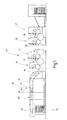
- Fig. 5
- eine teilweise weggeschnittene schematische Seitenansicht einer ogenoffsetdruckmaschine mit einer erfindungsgemäßen Vorrichtung zur Strahlungshärtung von mit Druckfarbe beschichteten bogenförmigen Substraten.
- Fig. 1
- a schematic side view of a device according to the invention for radiation curing of coated substrates;
- Fig. 2
- a rear perspective view of the device
Fig. 1 ; - Fig. 3
- a perspective rear view of a slightly modified device;
- Fig. 4
- a graph of the depth-resolved degree of conversion of unsaturated double bonds in a UV-cured substrate coating;
- Fig. 5
- a partially cut away schematic side view of a ogenoffsetdruckmaschine with a device according to the invention for radiation curing of ink-coated arcuate substrates.
Die in den
Wie am besten in
Die Bestrahlungskammer 6 dient als Lichtschutz für das Bedienungspersonal der Vorrichtungen 1 sowie zur kontinuierlichen Absaugung von eventuell anfallendem Ozon. Die Eintrittsöffnung 10 und die Austrittsöffnung 14 liegen sich an entgegengesetzten Seiten der Bestrahlungskammer 6 gegenüber, erstrecken sich jeweils vom Transportmittel 16 aus nach oben und sind normalerweise durch die Schieber 8 bzw. 12 verschlossen. Bei der Annäherung von einem der Objekte 2 an die Ein- bzw. Austrittsöffnung 10 bzw. 14 werden die Schieber 8 bzw. 12 kurzzeitig ausreichend weit nach oben bewegt, um die Objekte 2 durch die Öffnungen 10, 14 durchzulassen. Die Bewegung der Schieber 8, 12 wird von der Prozesssteuereinheit 28 ansprechend auf die Signale von Sensoren 30, 32 gesteuert, zum Beispiel berührungslosen optischen Sensoren, die jeweils in Transportrichtung T vor der Eintritts- bzw. Austrittsöffnung 10, 14 oberhalb des Transportmittels 16 angeordnet sind und beim Vorbeitritt eines Objekts 2 ein Signal zur Prozesssteuereinheit 28 senden.The
Das UV-Aggregat 18 enthält einen UV-Strahler 34 in Form einer Quecksilber-Mitteldruckgasentladungslampe, die quer zur Transportrichtung T der Objekte 2 ausgerichtet ist, sowie zwei oberhalb des UV-Strahlers 34 angeordnete Reflektoren 36, so dass das vom UV-Strahler emittierte UV-Licht nach unten in Richtung des Transportmittels 16 abgestrahlt wird und die auf dem Transportmittel 16 unter dem UV-Aggregat 18 hindurch bewegten Objekte 2 durch ein pyramidenstumpfförmiges Strahlungsfeld 38 des UV- Strahlers 34 hindurchtreten. Um eine gleichmäßige Bestrahlung der beschichteten Oberflächen der Objekte 2 sicherzustellen, können diese auf ihrem Bewegungsweg durch die Bestrahlungskammer 6 in Bezug zum Transportmittel 16 gedreht werden, wie durch die Pfeile A in
Bei dem UV-Aggregat 18 kann es sich um ein Bestrahlungsgerät handeln, durch das Stickstoff aus der Stickstoffquelle 26 als Kühlgas im Kreislauf geführt wird, ähnlich wie in der
Die in
Um die Menge des in die Bestrahlungskammer 6 zugeführten Stickstoffs weiter zu verringern, wird das Ventil 24 zwischen der Stickstoffquelle 24 und der Stickstoffzuführdüse 20 ansprechend auf ein Signal vom Sensor 30 und in Abhängigkeit von der Transportgeschwindigkeit des Transportmittels 16 so angesteuert, dass nur dann Stickstoff aus der Düse 20 in die Bestrahlungskammer 6 zugeführt wird, wenn eines der Objekte 6 so weit in das Strahlungsfeld 38 eingetreten ist, dass der aus der Düse 20 austretende Stickstoff auf die mit dem UV-Licht bestrahlte beschichtete Oberfläche des Objekts 2 auftrifft und dort die zu härtende Beschichtung kurzzeitig umspült oder anströmt. Außerdem wird das Ventil 24 sofort wieder geschlossen, nachdem das Objekt 2 aus dem Strahlungsfeld 38 ausgetreten bzw. vollständig durch den von der Düse 20 erzeugten Stickstoffvorhang hindurchgetreten ist. Der Zeitpunkt zum Schließen des Ventils 24 kann in Abhängigkeit von der Transportgeschwindigkeit des Transportmittels 16 und dem Zeitpunkt des Ansprechens des Sensors 30 berechnet werden. Alternativ kann jedoch auch ein vom Sensor 32 oder einem zusätzlichen Sensor (nicht dargestellt) stammendes Signal verwendet werden. Die Menge und die Dauer der Stickstoffzufuhr sind durch Veränderung des Öffnungsgrades und der Öffnungsdauer des Ventils 24 in der Ventilsteuereinheit 22 einstellbar, um Objekten 2 mit unterschiedlich großen Oberflächen bzw. Beschichtungen mit unterschiedlicher Zusammensetzung Rechnung zu tragen.In order to further reduce the amount of nitrogen fed into the
Im Hinblick auf eine weitere Reduzierung der in die Bestrahlungskammer 6 zugeführten Stickstoffmenge kann darüber hinaus eine gepulste Stickstoffzufuhr von Vorteil sein, d. h. ein intermittierendes kurzzeitiges Öffnen und Schließen des Ventils 24 zwischen der Stickstoffquelle 26 und der Düse 20 während der Dauer des Hindurchtritts eines Objekts 2 durch das Strahlungsfeld 38 bzw. durch den aus der Düse 20 auf das Objekt 2 geblasenen Stickstoffstrahl.In addition, with a view to further reducing the amount of nitrogen supplied to the
Die in
In einer hinter den Druckwerken 48, 50, 52 und dem Lackwerk 54 angeordneten Bogenauslage 58 befinden sich zwei IR-Aggregate 60 mit jeweils mehreren Infrarotstrahlern, die den Lack mit Infrarotlicht bestrahlen, um für einen guten Verlauf des Lacks zu sorgen. Weiter umfasst die Bogenauslage 58 zur vollständigen Aushärtung und Vernetzung der Druckfarbe hinter den IR-Aggregaten 60 drei UV-Aggregate 62, 64, 66, die wie die Aggregate 56 jeweils einen UV-Strahler aufweisen. Im Unterschied zu den Aggregaten 56 ist jedoch vor den drei Aggregaten 62, 64, 66 oder zwischen den Strahlungsfeldern zweier benachbarter Aggregaten zusätzlich eine Stickstoffzufuhrdüse (nicht dargestellt) vorgesehen, die sich über den Transportweg der Bogen erstreckt und schräg nach unten entgegen der Bogenlaufrichtung ausgerichtet ist, so dass der aus der Düse austretende Stickstoff innerhalb des Strahlungsfeldes des nachfolgenden Aggregats in Form eines schmalen, das Strahlungsfeld nicht ausfüllenden Gasstrahls auf die bedruckte Bogenoberfläche geblasen wird. Die Düse kann wie die Düse 20 aus den
Hinter den UV-Aggregaten 62, 64, 66 folgt noch ein Kühlaggregat 68, in dem die bedruckten Oberflächen der Bogen 46 mit Kühlluft beaufschlagt werden, damit sich der am Ende der Auslage 58 angeordnete Bogenstapel 70 nicht zu sehr erwärmt.Behind the
Claims (19)
Applications Claiming Priority (1)
| Application Number | Priority Date | Filing Date | Title |
|---|---|---|---|
| DE102007012263 | 2007-03-06 |
Publications (2)
| Publication Number | Publication Date |
|---|---|
| EP1967284A2 true EP1967284A2 (en) | 2008-09-10 |
| EP1967284A3 EP1967284A3 (en) | 2008-12-17 |
Family
ID=39577780
Family Applications (1)
| Application Number | Title | Priority Date | Filing Date |
|---|---|---|---|
| EP08152162A Withdrawn EP1967284A3 (en) | 2007-03-06 | 2008-02-29 | Method and device for UV-ray hardening of substrate layers |
Country Status (2)
| Country | Link |
|---|---|
| EP (1) | EP1967284A3 (en) |
| DE (1) | DE102008014269A1 (en) |
Cited By (12)
| Publication number | Priority date | Publication date | Assignee | Title |
|---|---|---|---|---|
| WO2008133498A2 (en) * | 2007-04-25 | 2008-11-06 | Trespa International B.V. | Apparatus and method for uv irradiation of one or more radiation-curable coatings |
| EP2666546A1 (en) * | 2012-05-25 | 2013-11-27 | Veka AG | Device for hardening varnish |
| EP2786807A1 (en) * | 2013-04-05 | 2014-10-08 | IOT - Innovative Oberflächentechnologie GmbH | Device for innertion with UV irradiation in open throughput systems |
| CN105413991A (en) * | 2015-12-08 | 2016-03-23 | 淮南纪兴源机电设备有限公司 | Reciprocating type UV curing machine |
| WO2017137211A1 (en) * | 2016-02-09 | 2017-08-17 | Heraeus Noblelight Gmbh | Device for the treatment of a substrate with uv radiation and use of the device |
| WO2017140522A1 (en) * | 2016-02-17 | 2017-08-24 | BEGO Bremer Goldschlägerei Wilh. Herbst GmbH & Co. KG | Post-exposure device for products produced by stereolithography, and method for solidifying products produced by stereolithography |
| US10683381B2 (en) | 2014-12-23 | 2020-06-16 | Bridgestone Americas Tire Operations, Llc | Actinic radiation curable polymeric mixtures, cured polymeric mixtures and related processes |
| CN113022161A (en) * | 2019-12-09 | 2021-06-25 | 精工爱普生株式会社 | Liquid ejecting apparatus |
| US11097531B2 (en) | 2015-12-17 | 2021-08-24 | Bridgestone Americas Tire Operations, Llc | Additive manufacturing cartridges and processes for producing cured polymeric products by additive manufacturing |
| IT202100001580A1 (en) * | 2021-01-27 | 2022-07-27 | Cefla Soc Cooperativa | APPARATUS AND METHOD FOR THE DRYING/POLYMERIZATION OF CHEMICAL PRODUCTS |
| US11453161B2 (en) | 2016-10-27 | 2022-09-27 | Bridgestone Americas Tire Operations, Llc | Processes for producing cured polymeric products by additive manufacturing |
| EP4067797A1 (en) * | 2021-01-27 | 2022-10-05 | Cefla Societa' Cooperativa | Apparatus and method for the drying/curing of chemical products |
Families Citing this family (1)
| Publication number | Priority date | Publication date | Assignee | Title |
|---|---|---|---|---|
| DE102013110450A1 (en) * | 2013-09-20 | 2015-03-26 | manroland sheetfed GmbH | Sheet-fed rotary offset printing press with facilities for drying radiation-curing special inks |
Citations (4)
| Publication number | Priority date | Publication date | Assignee | Title |
|---|---|---|---|---|
| EP1169611B1 (en) | 1999-04-13 | 2003-10-08 | IST METZ GmbH | Irradiating device |
| DE102004030674A1 (en) | 2004-06-24 | 2006-01-19 | Basf Ag | Apparatus and method for curing with high-energy radiation under an inert gas atmosphere |
| DE102005046233A1 (en) | 2004-10-01 | 2006-04-06 | Ist Metz Gmbh | Sheet-shaped substrate radiating unit, has channel system arranged outside of lamp space, so that lamp space remains free from cooling agent flow, and reflector formed with hollow section admitting cooling gas as part of channel system |
| DE10157554B4 (en) | 2001-11-23 | 2006-06-29 | Air Liquide Deutschland Gmbh | System for radiation hardening |
Family Cites Families (5)
| Publication number | Priority date | Publication date | Assignee | Title |
|---|---|---|---|---|
| DK0879146T3 (en) * | 1995-03-15 | 2001-06-18 | Nlm Combineering Aps | Method for activating photoinitiators in photosensitive substrates and apparatus for curing such substrates |
| AU1160897A (en) * | 1995-11-30 | 1997-06-19 | Harvey Clough | Apparatus for applying and curing radiation curable inks |
| US6550905B1 (en) * | 2001-11-19 | 2003-04-22 | Dotrix N.V. | Radiation curable inkjet ink relatively free of photoinitiator and method and apparatus of curing the ink |
| DE102005050371B4 (en) * | 2005-10-20 | 2012-08-16 | Sturm Maschinenbau Gmbh | Plant and method for radiation hardening of a coating of a workpiece under inert gas |
| US20070160743A1 (en) * | 2006-01-09 | 2007-07-12 | Babitt John L | Method for coating biocompatible material on a substrate |
-
2008
- 2008-02-29 EP EP08152162A patent/EP1967284A3/en not_active Withdrawn
- 2008-03-04 DE DE102008014269A patent/DE102008014269A1/en not_active Withdrawn
Patent Citations (4)
| Publication number | Priority date | Publication date | Assignee | Title |
|---|---|---|---|---|
| EP1169611B1 (en) | 1999-04-13 | 2003-10-08 | IST METZ GmbH | Irradiating device |
| DE10157554B4 (en) | 2001-11-23 | 2006-06-29 | Air Liquide Deutschland Gmbh | System for radiation hardening |
| DE102004030674A1 (en) | 2004-06-24 | 2006-01-19 | Basf Ag | Apparatus and method for curing with high-energy radiation under an inert gas atmosphere |
| DE102005046233A1 (en) | 2004-10-01 | 2006-04-06 | Ist Metz Gmbh | Sheet-shaped substrate radiating unit, has channel system arranged outside of lamp space, so that lamp space remains free from cooling agent flow, and reflector formed with hollow section admitting cooling gas as part of channel system |
Cited By (15)
| Publication number | Priority date | Publication date | Assignee | Title |
|---|---|---|---|---|
| WO2008133498A2 (en) * | 2007-04-25 | 2008-11-06 | Trespa International B.V. | Apparatus and method for uv irradiation of one or more radiation-curable coatings |
| WO2008133498A3 (en) * | 2007-04-25 | 2008-12-24 | Trespa Int Bv | Apparatus and method for uv irradiation of one or more radiation-curable coatings |
| EP2666546A1 (en) * | 2012-05-25 | 2013-11-27 | Veka AG | Device for hardening varnish |
| EP2786807A1 (en) * | 2013-04-05 | 2014-10-08 | IOT - Innovative Oberflächentechnologie GmbH | Device for innertion with UV irradiation in open throughput systems |
| US11926688B2 (en) | 2014-12-23 | 2024-03-12 | Bridgestone Americas Tire Operations, Llc | Actinic radiation curable polymeric mixtures, cured polymeric mixtures and related processes |
| US11261279B2 (en) | 2014-12-23 | 2022-03-01 | Bridgestone Americas Tire Operations, Llc | Actinic radiation curable polymeric mixtures, cured polymeric mixtures and related processes |
| US10683381B2 (en) | 2014-12-23 | 2020-06-16 | Bridgestone Americas Tire Operations, Llc | Actinic radiation curable polymeric mixtures, cured polymeric mixtures and related processes |
| CN105413991A (en) * | 2015-12-08 | 2016-03-23 | 淮南纪兴源机电设备有限公司 | Reciprocating type UV curing machine |
| US11097531B2 (en) | 2015-12-17 | 2021-08-24 | Bridgestone Americas Tire Operations, Llc | Additive manufacturing cartridges and processes for producing cured polymeric products by additive manufacturing |
| WO2017137211A1 (en) * | 2016-02-09 | 2017-08-17 | Heraeus Noblelight Gmbh | Device for the treatment of a substrate with uv radiation and use of the device |
| WO2017140522A1 (en) * | 2016-02-17 | 2017-08-24 | BEGO Bremer Goldschlägerei Wilh. Herbst GmbH & Co. KG | Post-exposure device for products produced by stereolithography, and method for solidifying products produced by stereolithography |
| US11453161B2 (en) | 2016-10-27 | 2022-09-27 | Bridgestone Americas Tire Operations, Llc | Processes for producing cured polymeric products by additive manufacturing |
| CN113022161A (en) * | 2019-12-09 | 2021-06-25 | 精工爱普生株式会社 | Liquid ejecting apparatus |
| IT202100001580A1 (en) * | 2021-01-27 | 2022-07-27 | Cefla Soc Cooperativa | APPARATUS AND METHOD FOR THE DRYING/POLYMERIZATION OF CHEMICAL PRODUCTS |
| EP4067797A1 (en) * | 2021-01-27 | 2022-10-05 | Cefla Societa' Cooperativa | Apparatus and method for the drying/curing of chemical products |
Also Published As
| Publication number | Publication date |
|---|---|
| DE102008014269A1 (en) | 2008-09-11 |
| EP1967284A3 (en) | 2008-12-17 |
Similar Documents
| Publication | Publication Date | Title |
|---|---|---|
| EP1967284A2 (en) | Method and device for UV-ray hardening of substrate layers | |
| WO1996034700A1 (en) | Method and device for hardening a layer on a substrate | |
| DE102015104321A1 (en) | Method, application device and printing device for applying a film | |
| EP2428359B1 (en) | Printer and method for printing on flat materials | |
| DE10051109C1 (en) | Hardening of coatings in an inert atmosphere using radiation, comprises using a tower construction with low parts entrance and exit, and a high irradiation source | |
| EP3867076B1 (en) | Method for printing on a surface of a nonabsorbent substrate with an ink to be applied by an inkjet printing device | |
| WO2008131831A2 (en) | Method for the production of ceramic films, and apparatus for carrying out said method | |
| DE102006057966B4 (en) | Customized irradiation system for electron beam curing | |
| EP1693198A2 (en) | Sheet-fed printing press | |
| EP2178704B1 (en) | Plasma treatment during printing | |
| WO2007003239A1 (en) | Device and method for the corona treatment of flat material | |
| EP3917780B1 (en) | Method and printing machine respectively for printing a metallic printable material | |
| EP1512467A1 (en) | Method and apparatus for the curing of a radiation-curable coating and irradiation chamber | |
| EP1353757B1 (en) | Device for coating an elongated workpiece | |
| EP4112307A1 (en) | Device for curing a uv-curable fluid on a printing substrate with a radiator | |
| WO2003089244A2 (en) | Device for printing printing material embodied as metal sheets, and corresponding method | |
| DE102015204555B4 (en) | Apparatus for drying a radiation-curing medium on a sheet-shaped printing substrate | |
| DE102004033260A1 (en) | Radiation induced curing of paint, in particular UV curable paints on vehicle body parts, uses radiant heater for heating paint and further radiation emitter to induce curing of paint layer | |
| EP2058614A2 (en) | Device to irradiate elements with UV/light and method of its operation | |
| DE102022126297A1 (en) | Device and method for coating a cylindrical body with a polymer | |
| WO2024078764A1 (en) | Device and method for curing a polymer layer on a cylindrical body | |
| DE102022123022A1 (en) | Direct printing device with UV lighting device | |
| DE102009051174B4 (en) | Method and device for finishing a printed product by means of powder coating | |
| DE102009048824A1 (en) | Radiation curing device for workpieces in automobile industry, has flow mechanism arranged in line such that gas in cycle is led in section of pipe, where cycle is connected with supply mechanism, so that inert gas is formed in cycle | |
| EP1395784A1 (en) | Method and device for drying |
Legal Events
| Date | Code | Title | Description |
|---|---|---|---|
| PUAI | Public reference made under article 153(3) epc to a published international application that has entered the european phase |
Free format text: ORIGINAL CODE: 0009012 |
|
| AK | Designated contracting states |
Kind code of ref document: A2 Designated state(s): AT BE BG CH CY CZ DE DK EE ES FI FR GB GR HR HU IE IS IT LI LT LU LV MC MT NL NO PL PT RO SE SI SK TR |
|
| AX | Request for extension of the european patent |
Extension state: AL BA MK RS |
|
| PUAL | Search report despatched |
Free format text: ORIGINAL CODE: 0009013 |
|
| AK | Designated contracting states |
Kind code of ref document: A3 Designated state(s): AT BE BG CH CY CZ DE DK EE ES FI FR GB GR HR HU IE IS IT LI LT LU LV MC MT NL NO PL PT RO SE SI SK TR |
|
| AX | Request for extension of the european patent |
Extension state: AL BA MK RS |
|
| RIC1 | Information provided on ipc code assigned before grant |
Ipc: B05D 3/04 20060101ALI20081110BHEP Ipc: B05D 3/06 20060101ALI20081110BHEP Ipc: G21K 5/00 20060101ALI20081110BHEP Ipc: F26B 21/14 20060101ALI20081110BHEP Ipc: F26B 13/00 20060101ALI20081110BHEP Ipc: F26B 3/34 20060101ALI20081110BHEP Ipc: F26B 3/28 20060101ALI20081110BHEP Ipc: C09D 11/10 20060101ALI20081110BHEP Ipc: B41F 23/00 20060101ALI20081110BHEP Ipc: B41F 23/04 20060101ALI20081110BHEP Ipc: B05D 3/00 20060101ALI20081110BHEP Ipc: B01J 19/12 20060101AFI20081110BHEP |
|
| 17P | Request for examination filed |
Effective date: 20090617 |
|
| AKX | Designation fees paid |
Designated state(s): AT BE BG CH CY CZ DE DK EE ES FI FR GB GR HR HU IE IS IT LI LT LU LV MC MT NL NO PL PT RO SE SI SK TR |
|
| 17Q | First examination report despatched |
Effective date: 20090923 |
|
| STAA | Information on the status of an ep patent application or granted ep patent |
Free format text: STATUS: THE APPLICATION IS DEEMED TO BE WITHDRAWN |
|
| 18D | Application deemed to be withdrawn |
Effective date: 20100406 |