EP1967149A1 - Compresseur-distracteur - Google Patents
Compresseur-distracteur Download PDFInfo
- Publication number
- EP1967149A1 EP1967149A1 EP06769543A EP06769543A EP1967149A1 EP 1967149 A1 EP1967149 A1 EP 1967149A1 EP 06769543 A EP06769543 A EP 06769543A EP 06769543 A EP06769543 A EP 06769543A EP 1967149 A1 EP1967149 A1 EP 1967149A1
- Authority
- EP
- European Patent Office
- Prior art keywords
- external
- threaded
- holes
- rings
- bolt
- Prior art date
- Legal status (The legal status is an assumption and is not a legal conclusion. Google has not performed a legal analysis and makes no representation as to the accuracy of the status listed.)
- Withdrawn
Links
Images


Classifications
-
- A—HUMAN NECESSITIES
- A61—MEDICAL OR VETERINARY SCIENCE; HYGIENE
- A61B—DIAGNOSIS; SURGERY; IDENTIFICATION
- A61B17/00—Surgical instruments, devices or methods, e.g. tourniquets
- A61B17/56—Surgical instruments or methods for treatment of bones or joints; Devices specially adapted therefor
- A61B17/58—Surgical instruments or methods for treatment of bones or joints; Devices specially adapted therefor for osteosynthesis, e.g. bone plates, screws, setting implements or the like
- A61B17/60—Surgical instruments or methods for treatment of bones or joints; Devices specially adapted therefor for osteosynthesis, e.g. bone plates, screws, setting implements or the like for external osteosynthesis, e.g. distractors, contractors
- A61B17/62—Ring frames, i.e. devices extending around the bones to be positioned
-
- A—HUMAN NECESSITIES
- A61—MEDICAL OR VETERINARY SCIENCE; HYGIENE
- A61B—DIAGNOSIS; SURGERY; IDENTIFICATION
- A61B17/00—Surgical instruments, devices or methods, e.g. tourniquets
- A61B17/56—Surgical instruments or methods for treatment of bones or joints; Devices specially adapted therefor
- A61B17/58—Surgical instruments or methods for treatment of bones or joints; Devices specially adapted therefor for osteosynthesis, e.g. bone plates, screws, setting implements or the like
- A61B17/60—Surgical instruments or methods for treatment of bones or joints; Devices specially adapted therefor for osteosynthesis, e.g. bone plates, screws, setting implements or the like for external osteosynthesis, e.g. distractors, contractors
- A61B17/66—Alignment, compression or distraction mechanisms
Definitions
- the invention relates to the medical field, particularly to traumatology and orthopedics, and may be utilized for the treating of patients with bone injuries and diseases of extremities.
- a compression-distraction device comprising supports in the form of sectional, coaxially disposed relatively to each other rings, one of them is inner with a ring gear on the external butt, another - external with lugs supplied with holes, and also rods, reposition units, bone fixators fixed on the inner rings, removable key with a star-shaped head, locking element and fixation elements (A.C. No 1132934 (USSR), Published 07.01.1985, Bulletin No 1).
- this device is mainly intended for the length reconstruction of the segments of extremities, and also for the reposition of fragments at fractures with slight displacements.
- This device in view of its constructive features can't be efficiently used for the reducing of the complex multi-component deformations. It's caused both by the connection of supports schema and the reposition units construction which don't provide the prevention of the repeated displacement of the fragments during the reposition. Besides, in the construction under consideration the reducing of one kind of fragments displacement needs to make some consistent or synchronous manipulations, which makes difficult the exploitation of the apparatus.
- the object of the invention is to design the construction of the compression-distraction apparatus, which would allow to simplify its exploitation and to extend the functional possibilities at the treating of patients with the shortenings of the segments of extremity, combining with the multi-component deformation.
- the compression-distraction apparatus comprising the supports in the form of sectional, coaxially disposed relatively to each other rings, one of them is inner with a ring gear on the external butt, another - external with lugs supplied with holes, threaded rods, reposition units, bone fixators held on the inner rings, locking element and fixing elements in the form of washers, nuts and fixing bolts, the external ring is formed with the slot for the ring gear on the inner butt, the holes in the lugs are intended for the threaded rods, but, at least one of these holes is communicated with the slot on the inner butt - for the locking element, the component inner rings of the sector having the holes on the ends, commensurable with the slot and the jut, and the external ones - are shaped as a L-reversed and commensurable with the rectangular slot on the external side, with the hollow for the thread bushing - on the inner side, the groove which is coaxial with the hole of bush
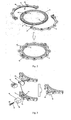
- the compression-distraction apparatus ( Fig. 1 ) consists of the supports 1 and 2 in the form of sectional, coaxially placed, with the displacement possibility relatively to each other, the inner - 3, and the external rings - 4, comprising, accordingly, the sectors 5, 6, 7, 8 ( Fig. 2 ).
- the sectors 5,6 of the inner ring 3 are interconnected on their ends by the commensurable slots 9 and the juts 10 with holes 11.
- the ends of sectors 7, 8 of the external ring 4 are shaped as a L-reversed, with rectangular slots 12 - on the external side, commensurable with the hollow 13 for the thread bushing 14 - on the inner side and the groove 15 which is coaxial with the hole of bushing 14 for the fixing bolt - on the butt, and are secured by the fixing clamp 16 ( Fig. 3 ) placed on them, the clamp is supplied with the juts 17 on the ends, conforming to the slots 12 on the external surface of the sectors, and the groove 18 formed for the fixing bolt 19 with the circular flute 20 in the base of head - on the inner surface of the butt.
- the inner rings 3 are supplied with the ring gear 21 on the external butt, and the external rings 4 - by the slot 22 for the ring gear 21 - on the inner and the external butt - with lugs 23, holes 24, at least one of them is communicated with the slot 22 ( Fig. 2 ).
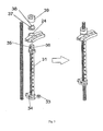
- Supports 1, 2 are interconnected by the threaded rods 25, 26, 27, 28 and the reposition units 29, 30.
- threaded rods with the displacement possibility are placed into the cartridges 31 ( Fig. 5 ) having the flank hollow 32 for the moving nut 33 and the threaded hole for the contacting locking bolt 34 on one of the ends; on the other end ⁇ the external thread 35 and the sector hollow 36, by means of which and also of the washer 37 with the sector jut 38 conforming to the hollow 36, and the nut 39 the threaded rods are firmly fixed in the holes 24 of lugs 23 of the external rings 4 of supports 1, 2. It's also foreseen that the fixing end of the cartridge 31 ( Fig.
- the commensurable ends might interconnect the cartridges 31 with the inner thread 40 on one of the ends and the cartridges with the external thread 35 and the sector hollow 36 on one of the ends by means of the washer 37 with the sector jut 38, at the fixing of the intermediate support in the holes 24 of the lugs 23.
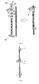
- the threaded rods 25, 26, 27, 28 placed into the cartridges 31 are fixed in pairs on the parallely placed threaded bars 45, 46 interconnecting with the reposition units 29, 30 by means of the jaws 47 hinged with the bushings 48 placed on the bars with displacement possibility.
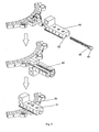
- Each of the reposition units 29, 30 is shaped as a L-reversed slider 49 ( Fig. 8 ), the frame of which has the holes for the threaded bars 45, 46, the juts 50 and the holes 51 for the locking bolt 52 - in the base of the frame, and also the groove 53 ⁇ on the butt of the base.
- the slider 49 is sectional ( Fig. 9 ) and supplied with the figured hollows 54 on the flank sides of the base conforming to the stems 55 of the removable bracket 56 with holes 57 for the threaded bars 45, 46.
- the slider 49 with the displacement possibility is placed in the rectangular slots 12 on the external surface of the curves shaped as a L-reversed of the confronted ends of sectors 7, 8 of external rings 4 and fixed by the locking bolt 52 and the fixing bolt 19 with the circular flute 20, let pass through the groove 53, confronted grooves 15 and put into the thread bushing 14 situated in the confronted hollows 13.
- the cartridges 31, threaded bars 45, 46 and sliders 49 are supplied with a metric scale 58, a degree scale 59 on the butt of the external ring 4, and a landmark sign 60 - on the surface of the ducted bolt 41.
- the cartridges 31 have the longitudinal through slots 61 and the landmark sign 62 - on the surface of the end fixed on the support ( Fig. 1 , 3 , 5 , 6 , 8 ).
- the apparatus is provided with the locking element ( Fig. 10 ) in the form of the bolt 63 with the support plate 64 in the base of head and with cogs 65 along the perimeter of its stem and also washers 66 with the pad 67 along the perimeter of the hole and the nut for the stabilization and the rotary displacement of the rings 3, 4 of supports 1, 2 relatively to each other.
- the bone fixators ⁇ the pins 69 are directly secured by the bolts-fixators 72, the rods 70 - indirectly, by the brackets 71 on the inner rings 3 of supports 1, 2.
- the compression-distraction apparatus is used as follows.
- the supports 1, 2 are interconnected by the confronted ends of sectors 7, 8 fixed on the curves shaped as a L-reversed of the external rings 4, the reposition units 29, 30 and the threaded rods 25, 26, 27 and 28 placed in the cartridges 31.
- the end of one of the cartridges 31 is introduced into the hole 24 of lug 23; for example, the end of the cartridge 31 having the external thread 35 with the sector hollow 36 and the washer 37 with the sector jut 38 preliminary placed on it is screwed in the cartridge with the inner thread 40.
- the mounting of cartridges is corrected from the landmark signs 60 and 62 on the ducted bolts 41 and on the ends of cartridges 31 with the external thread; the landmark signs 60 and 62 must be confronted to the sign of the degree scale 59, marked on the lug 23 of the external ring 4.
- the threaded rods 25, 26, 27 and 28 situated in the cartridges 31 are fixed in pairs on the parallely placed threaded bars 45, 46 interconnecting with the reposition units 29, 30.
- the fixing is made up by means of the jaws 47 hinged to the bushings 48 with displacement possibility, which are placed on the mentioned bars.
- the position of the rods 25, 26, 27 and 28 is fixed by means of the locking bolt 34 contacting with the moving nut 33 mounted on the rod and placed in the hollows 32 of the cartridges 31.
- the angle displacement of the supports needs the dissymmetry rotation of the moving nuts 33 with the displacement of the rods, for example, the rods 25 and 27 placed in the concave side of the deformation ⁇ in a one direction, accordingly, the rods 26 and 28 placed in the convex side of the deformation - in a opposite direction.
- the simultaneous lengthening and reducing of the angle deformation of the segment needs the rotation of the moving nuts 33 in a one direction, but the rods 25 and 27 placed in the concave side of the deformation - on the larger size, and the rods 26 and 28 placed in the convex side of the deformation - on the smaller size.
- the lateral displacements (on width" in the deformation plane and in its perpendicular plane) are made up by means of reposition units 29, 30.
- the fixing nuts 75 stabilizing the position of the threaded bars 45, 46 or the bolt 19 fixing the position of the slider 49 are rotated in a one or another direction.
- the locking element is used for the displacement of the supports relatively to each other. For that it's necessary to loosen the pull of the bolt 63 fitted in the hole 24 of the lug 23, contacting to the cogs 65 of the ring gear 21 with its turning in the needed direction and to realize the rotation of the supports. Then the washer 66 is screwed and tightened on the stem end of the bolt 63 jutting of the opposite side of the hole 24, the pad 67 conforming to the perimeter of the hole of washer is introduced to the hole 24, the fixing nut 75 is tightened to stabilize the position of the rings 3, 4. All kinds of displacement of the fixing bone fragments can be reduced by the combination or the modification of the consecution of above-mentioned manipulations.
- the displacement size of the supports is visually controlled with the help of the metric and degree scales 58, 59, accordingly, on the cartridges 31, the bars 45, 46, the butts of the external rings 4, and also with the help of the through slots 61 on the cartridges 31.
- the proposed apparatus is simple in use and has many functional possibilities for the treatment of patients with shortenings of the segments of extremity, combining with its multi-component deformation.
- the minimum of details composing the uniform assembling makes possible to reduce the time of the apparatus mounting for all kinds of deformations and displacements of the bone fragments; to simplify the manipulations, to raise the exactness of the correction; to make easier the postoperative management of patients, to refuse of the periodical apparatus remounting.
- the mentioned advantages allow using this construction with electron-digital devices with software, for the osteosynthesis in the automatic mode.
Landscapes
- Health & Medical Sciences (AREA)
- Orthopedic Medicine & Surgery (AREA)
- Life Sciences & Earth Sciences (AREA)
- Surgery (AREA)
- Biomedical Technology (AREA)
- Engineering & Computer Science (AREA)
- Nuclear Medicine, Radiotherapy & Molecular Imaging (AREA)
- Heart & Thoracic Surgery (AREA)
- Medical Informatics (AREA)
- Molecular Biology (AREA)
- Animal Behavior & Ethology (AREA)
- General Health & Medical Sciences (AREA)
- Public Health (AREA)
- Veterinary Medicine (AREA)
- Surgical Instruments (AREA)
Applications Claiming Priority (2)
| Application Number | Priority Date | Filing Date | Title |
|---|---|---|---|
| RU2005141637/14A RU2357699C2 (ru) | 2005-12-29 | 2005-12-29 | Компрессионно-дистракционный аппарат |
| PCT/RU2006/000302 WO2007075114A1 (fr) | 2005-12-29 | 2006-06-13 | Compresseur-distracteur |
Publications (2)
| Publication Number | Publication Date |
|---|---|
| EP1967149A1 true EP1967149A1 (fr) | 2008-09-10 |
| EP1967149A4 EP1967149A4 (fr) | 2010-05-05 |
Family
ID=38218269
Family Applications (1)
| Application Number | Title | Priority Date | Filing Date |
|---|---|---|---|
| EP06769543A Withdrawn EP1967149A4 (fr) | 2005-12-29 | 2006-06-13 | Compresseur-distracteur |
Country Status (8)
| Country | Link |
|---|---|
| US (1) | US20090177198A1 (fr) |
| EP (1) | EP1967149A4 (fr) |
| JP (1) | JP3150204U (fr) |
| CA (1) | CA2633944A1 (fr) |
| DE (1) | DE202006020487U1 (fr) |
| RU (1) | RU2357699C2 (fr) |
| WO (1) | WO2007075114A1 (fr) |
| ZA (1) | ZA200806011B (fr) |
Cited By (4)
| Publication number | Priority date | Publication date | Assignee | Title |
|---|---|---|---|---|
| WO2011026475A1 (fr) * | 2009-09-05 | 2011-03-10 | Surgitaix Ag | Dispositif de fixation de segments osseux |
| CN105919659A (zh) * | 2016-06-27 | 2016-09-07 | 重庆富沃思医疗器械有限公司 | 一种用于可调式固定支具的盆骨固定套组件 |
| EP3127498A4 (fr) * | 2014-04-04 | 2018-03-07 | Tovarishchestvo S Ogranichennoy Otvetstvennostiyu | Appareil de compression-distraction de f. a. matsukatov et unité de réduction pour celui-ci |
| CN109077786A (zh) * | 2018-08-03 | 2018-12-25 | 天津大学 | 全对称三支链并联外固定支架 |
Families Citing this family (50)
| Publication number | Priority date | Publication date | Assignee | Title |
|---|---|---|---|---|
| WO2009100247A1 (fr) * | 2008-02-05 | 2009-08-13 | Texas Scottish Rite Hospital For Children | Anneau de fixation externe |
| JP5507472B2 (ja) | 2008-02-08 | 2014-05-28 | テキサス スコティッシュ ライト ホスピタル フォー チルドレン | 創外固定支柱 |
| JP5667882B2 (ja) | 2008-02-12 | 2015-02-12 | テキサス スコティッシュ ライト ホスピタル フォー チルドレン | 創外固定用接続棒の迅速な調節 |
| JP5529047B2 (ja) | 2008-02-18 | 2014-06-25 | テキサス スコティッシュ ライト ホスピタル フォー チルドレン | 創外固定支柱調整のツール及び方法 |
| EP2110089A1 (fr) | 2008-04-18 | 2009-10-21 | Stryker Trauma SA | Plaque de fixation orthopédique |
| EP2110090A1 (fr) | 2008-04-18 | 2009-10-21 | Stryker Trauma SA | Plaque de fixation orthopédique perméable aux rayons X |
| US8858555B2 (en) | 2009-10-05 | 2014-10-14 | Stryker Trauma Sa | Dynamic external fixator and methods for use |
| US8257353B2 (en) * | 2010-02-24 | 2012-09-04 | Wright Medical Technology, Inc. | Orthopedic external fixation device |
| GB201008281D0 (en) | 2010-05-19 | 2010-06-30 | Nikonovas Arkadijus | Indirect analysis and manipulation of objects |
| ES2446370T3 (es) | 2010-08-11 | 2014-03-07 | Stryker Trauma Sa | Sistema fijador externo |
| US11141196B2 (en) | 2010-08-11 | 2021-10-12 | Stryker European Operations Holdings Llc | External fixator system |
| US8945128B2 (en) | 2010-08-11 | 2015-02-03 | Stryker Trauma Sa | External fixator system |
| CA2809002C (fr) | 2010-08-20 | 2017-11-21 | Amei Technologies, Inc. | Procede et systeme permettant une modelisation basee sur une radiographie |
| US9265529B2 (en) * | 2010-11-30 | 2016-02-23 | Nikolaj Wolfson | Orthopedic fixation systems and methods |
| US9907582B1 (en) | 2011-04-25 | 2018-03-06 | Nuvasive, Inc. | Minimally invasive spinal fixation system and related methods |
| RU2480176C1 (ru) * | 2011-10-25 | 2013-04-27 | Федеральное государственное бюджетное учреждение "Российский ордена Трудового Красного Знамени научно-исследовательский институт травматологии и ортопедии им. Р.Р. Вредена" Министерства здравоохранения и социального развития Российской Федерации (ФГБУ "РНИИТО им. Р.Р. Вредена" Минздравсоцразвития Ро | Способ коррекции формы голени с использованием чрескостного остеосинтеза и стержень-шуруп для его выполнения |
| CN102715973A (zh) * | 2012-06-27 | 2012-10-10 | 哈尔滨首创骨科微创医疗设备有限公司 | 一种闭合整复骨折外固定架 |
| US9101398B2 (en) | 2012-08-23 | 2015-08-11 | Stryker Trauma Sa | Bone transport external fixation frame |
| CA2883395C (fr) * | 2012-09-06 | 2018-05-01 | Solana Surgical, Llc | Fixateur externe |
| ITGE20120093A1 (it) * | 2012-09-14 | 2014-03-15 | Mikai S P A | Fissatore circolare esterno |
| US8574232B1 (en) | 2012-11-13 | 2013-11-05 | Texas Scottish Hospital for Children | External fixation connection rod for rapid and gradual adjustment |
| US9039706B2 (en) | 2013-03-13 | 2015-05-26 | DePuy Synthes Products, Inc. | External bone fixation device |
| CA2905865C (fr) | 2013-03-13 | 2021-03-02 | DePuy Synthes Products, Inc. | Dispositif de fixation osseuse externe |
| RU2572302C2 (ru) * | 2013-07-05 | 2016-01-10 | Государственное бюджетное образовательное учреждение высшего профессионального образования "Дагестанская государственная медицинская академия" Министерства здравоохранения РФ | Устройство для репозиции костных отломков в аппарате илизарова |
| CN104434282B (zh) * | 2013-09-13 | 2016-08-24 | 贝尔泰克医疗器械江苏有限公司 | 一种用于骨延长术的外固定支架 |
| CN103462674B (zh) * | 2013-09-17 | 2015-07-15 | 北京航空航天大学 | 一种可拆装式长骨复位机器人 |
| US9717528B2 (en) | 2014-04-01 | 2017-08-01 | Stryker European Holdings I, Llc | External fixator with Y strut |
| CN106794033B (zh) * | 2014-08-14 | 2019-05-21 | 兰博基尼汽车公开有限公司 | 用于外部矫形固定的装置 |
| US9936975B2 (en) | 2014-09-09 | 2018-04-10 | Integra Lifesciences Corporation | External fixation system |
| RU2572300C1 (ru) * | 2014-09-17 | 2016-01-10 | Государственное бюджетное образовательное учреждение высшего профессионального образования "Дагестанская государственная медицинская академия" Министерства здравоохранения РФ | Устройство для внеочагового остеосинтеза открытых переломов голени |
| CN104323839B (zh) * | 2014-10-24 | 2016-12-07 | 河南盛世伟业医疗器械制造有限公司 | 一种直筒式骨外固定器 |
| US10010346B2 (en) | 2016-04-20 | 2018-07-03 | Stryker European Holdings I, Llc | Ring hole planning for external fixation frames |
| US10010350B2 (en) | 2016-06-14 | 2018-07-03 | Stryker European Holdings I, Llc | Gear mechanisms for fixation frame struts |
| US10835318B2 (en) | 2016-08-25 | 2020-11-17 | DePuy Synthes Products, Inc. | Orthopedic fixation control and manipulation |
| CN106308905A (zh) * | 2016-11-07 | 2017-01-11 | 河南理工大学 | 一种骨折矫正固定装置 |
| US10874433B2 (en) | 2017-01-30 | 2020-12-29 | Stryker European Holdings I, Llc | Strut attachments for external fixation frame |
| US11457953B2 (en) * | 2017-08-31 | 2022-10-04 | J & A Medical Llc | External fixation alignment gauge |
| CN107669390B (zh) * | 2017-09-30 | 2020-02-14 | 吉林大学 | 一种能做手臂弯曲练习的手臂复健装置 |
| CN107569278B (zh) * | 2017-10-25 | 2018-06-08 | 河南中医药大学 | 骨科手术辅助器 |
| RU2680593C1 (ru) * | 2017-12-20 | 2019-02-22 | Игорь Георгиевич Киселев | Ортопедический трансформер |
| CN108478266B (zh) * | 2018-03-26 | 2020-11-06 | 天津大学 | 自由连接式三支链并联骨科外固定支架 |
| CN110495937A (zh) * | 2018-05-18 | 2019-11-26 | 武汉德骼拜尔外科植入物有限公司 | 环形外固定支架和固定装置 |
| CN108742804B (zh) * | 2018-06-05 | 2020-04-07 | 天津大学 | 一种用于骨折复位的并联外固定支架 |
| EP3860481A4 (fr) | 2018-10-04 | 2022-05-18 | University of Utah Research Foundation | Fixateur torsionnel couplé et procédé d'utilisation |
| CN109480980B (zh) * | 2019-01-05 | 2024-05-07 | 陈聚伍 | 多维柔性骨折复位装置 |
| US11439436B2 (en) | 2019-03-18 | 2022-09-13 | Synthes Gmbh | Orthopedic fixation strut swapping |
| US11304757B2 (en) | 2019-03-28 | 2022-04-19 | Synthes Gmbh | Orthopedic fixation control and visualization |
| US11334997B2 (en) | 2020-04-03 | 2022-05-17 | Synthes Gmbh | Hinge detection for orthopedic fixation |
| US11589900B2 (en) * | 2020-05-06 | 2023-02-28 | William MONTROSS | Modular frame |
| CN111956313A (zh) * | 2020-08-14 | 2020-11-20 | 中国人民解放军联勤保障部队第九二0医院 | 手掌骨延长装置 |
Citations (3)
| Publication number | Priority date | Publication date | Assignee | Title |
|---|---|---|---|---|
| SU1055499A1 (ru) * | 1981-10-14 | 1983-11-23 | Курганский Научно-Исследовательский Институт Экспериментальной И Клинической Ортопедии И Травматологии | Аппарат Г.А.Илизарова дл чрезкостного остеосинтеза |
| WO1996034585A1 (fr) * | 1995-05-03 | 1996-11-07 | Fugang Tang | Systeme de repositionnement et de fixation de fracture |
| WO2003086211A1 (fr) * | 2002-04-12 | 2003-10-23 | Fu Han | Dispositif de fixation et de restitution externe d'osteoplastie |
Family Cites Families (5)
| Publication number | Priority date | Publication date | Assignee | Title |
|---|---|---|---|---|
| SU1132934A1 (ru) * | 1983-04-25 | 1985-01-07 | Zherebnoj Mikhail A | Компрессионно-дистракционное устройство (его варианты) |
| SU1360718A1 (ru) * | 1986-04-14 | 1987-12-23 | В. 3. Полетанский | Компрессионно-дистракционный аппарат |
| RU2064783C1 (ru) * | 1993-12-16 | 1996-08-10 | Анатолий Львович Матвеев | Компрессионно-дистракционный аппарат |
| US5496319A (en) * | 1994-06-27 | 1996-03-05 | Zimmer, Inc. | External fixation apparatus |
| US5863292A (en) * | 1996-09-26 | 1999-01-26 | Tosic; Aleksandar | Articulated external orthopedic fixation system and method of use |
-
2005
- 2005-12-29 RU RU2005141637/14A patent/RU2357699C2/ru active IP Right Revival
-
2006
- 2006-06-13 CA CA002633944A patent/CA2633944A1/fr not_active Abandoned
- 2006-06-13 WO PCT/RU2006/000302 patent/WO2007075114A1/fr active Application Filing
- 2006-06-13 JP JP2008600036U patent/JP3150204U/ja not_active Expired - Fee Related
- 2006-06-13 US US12/159,551 patent/US20090177198A1/en not_active Abandoned
- 2006-06-13 DE DE202006020487U patent/DE202006020487U1/de not_active Expired - Lifetime
- 2006-06-13 EP EP06769543A patent/EP1967149A4/fr not_active Withdrawn
-
2008
- 2008-07-10 ZA ZA200806011A patent/ZA200806011B/xx unknown
Patent Citations (3)
| Publication number | Priority date | Publication date | Assignee | Title |
|---|---|---|---|---|
| SU1055499A1 (ru) * | 1981-10-14 | 1983-11-23 | Курганский Научно-Исследовательский Институт Экспериментальной И Клинической Ортопедии И Травматологии | Аппарат Г.А.Илизарова дл чрезкостного остеосинтеза |
| WO1996034585A1 (fr) * | 1995-05-03 | 1996-11-07 | Fugang Tang | Systeme de repositionnement et de fixation de fracture |
| WO2003086211A1 (fr) * | 2002-04-12 | 2003-10-23 | Fu Han | Dispositif de fixation et de restitution externe d'osteoplastie |
Non-Patent Citations (1)
| Title |
|---|
| See also references of WO2007075114A1 * |
Cited By (5)
| Publication number | Priority date | Publication date | Assignee | Title |
|---|---|---|---|---|
| WO2011026475A1 (fr) * | 2009-09-05 | 2011-03-10 | Surgitaix Ag | Dispositif de fixation de segments osseux |
| EP3127498A4 (fr) * | 2014-04-04 | 2018-03-07 | Tovarishchestvo S Ogranichennoy Otvetstvennostiyu | Appareil de compression-distraction de f. a. matsukatov et unité de réduction pour celui-ci |
| EP3409224A1 (fr) * | 2014-04-04 | 2018-12-05 | Tovarishchestvo S Ogranichennoy Otvetstvennostiyu | Appareil de compression-distraction f.a. matsukatov et ensemble pour le repositionner |
| CN105919659A (zh) * | 2016-06-27 | 2016-09-07 | 重庆富沃思医疗器械有限公司 | 一种用于可调式固定支具的盆骨固定套组件 |
| CN109077786A (zh) * | 2018-08-03 | 2018-12-25 | 天津大学 | 全对称三支链并联外固定支架 |
Also Published As
| Publication number | Publication date |
|---|---|
| EP1967149A4 (fr) | 2010-05-05 |
| US20090177198A1 (en) | 2009-07-09 |
| CA2633944A1 (fr) | 2007-07-05 |
| JP3150204U (ja) | 2009-05-07 |
| DE202006020487U1 (de) | 2008-10-02 |
| ZA200806011B (en) | 2009-10-28 |
| RU2005141637A (ru) | 2007-07-10 |
| WO2007075114A1 (fr) | 2007-07-05 |
| RU2357699C2 (ru) | 2009-06-10 |
Similar Documents
| Publication | Publication Date | Title |
|---|---|---|
| EP1967149A1 (fr) | Compresseur-distracteur | |
| US4624249A (en) | Orthopedic external fixing apparatus | |
| US7306601B2 (en) | External fixation system with provisional brace | |
| US20160310168A1 (en) | Dynamization module for external fixation strut | |
| US6585736B2 (en) | Device for external fixation of a fractured radius with simultaneous clamping of multiple pins and with a fixture for applying extension to distal bone fragments | |
| KR200443058Y1 (ko) | 압축-신연 장치 | |
| JPH07416A (ja) | 骨固定外部システム用平行移動/回転装置 | |
| US10925645B2 (en) | External fixator | |
| CA2559497C (fr) | Element de fixation externe pour osteosynthese | |
| CN109124784B (zh) | 一种膝关节周围截骨术足踝固定器 | |
| RU179089U1 (ru) | Опора аппарата внешней фиксации для костей стопы | |
| CN217772477U (zh) | 一种横向骨搬移外固定支架 | |
| CN114209406A (zh) | 一种跟骨骨折关节面的复位器械及其使用方法 | |
| RU2314767C1 (ru) | Аппарат внешней фиксации для интраоперационной репозиции и стабилизации положения посттравматических отломков костей | |
| RU80332U1 (ru) | Аппарат для лечения патологии бедра | |
| RU2281716C1 (ru) | Аппарат внешней фиксации | |
| ITVI980244A1 (it) | Struttura di fissatore esterno per il trattamento di fratture, dislocazioni e rigidita' post-traumatiche dell'articolazione del gomito. | |
| SU1475625A1 (ru) | Телескопическа балка | |
| RU2281054C1 (ru) | Аппарат внешней фиксации | |
| RU2687610C2 (ru) | Ортопедический трансформер | |
| RU182367U1 (ru) | Устройство для репозиции и фиксации кости | |
| RU2272593C2 (ru) | Стержневой аппарат для чрескостного остеосинтеза | |
| RU2319467C2 (ru) | Стержневой аппарат для чрескостного остеосинтеза | |
| RU2260397C1 (ru) | Компрессионно-дистракционный аппарат | |
| RU2306897C1 (ru) | Аппарат внешней фиксации |
Legal Events
| Date | Code | Title | Description |
|---|---|---|---|
| PUAI | Public reference made under article 153(3) epc to a published international application that has entered the european phase |
Free format text: ORIGINAL CODE: 0009012 |
|
| 17P | Request for examination filed |
Effective date: 20080627 |
|
| AK | Designated contracting states |
Kind code of ref document: A1 Designated state(s): AT BE BG CH CY CZ DE DK EE ES FI FR GB GR HU IE IS IT LI LT LU LV MC NL PL PT RO SE SI SK TR |
|
| A4 | Supplementary search report drawn up and despatched |
Effective date: 20100408 |
|
| STAA | Information on the status of an ep patent application or granted ep patent |
Free format text: STATUS: THE APPLICATION HAS BEEN WITHDRAWN |
|
| 18W | Application withdrawn |
Effective date: 20110803 |