EP1966573B1 - Konverter mit einem behälter zur aufnahme geschmolzenen metalls und einer messvorrichtung zur optischen temperaturbestimmung des geschmolzenen metalls sowie verfahren zur temperaturbestimmung in einem derartigen konverter - Google Patents
Konverter mit einem behälter zur aufnahme geschmolzenen metalls und einer messvorrichtung zur optischen temperaturbestimmung des geschmolzenen metalls sowie verfahren zur temperaturbestimmung in einem derartigen konverter Download PDFInfo
- Publication number
- EP1966573B1 EP1966573B1 EP06829582.3A EP06829582A EP1966573B1 EP 1966573 B1 EP1966573 B1 EP 1966573B1 EP 06829582 A EP06829582 A EP 06829582A EP 1966573 B1 EP1966573 B1 EP 1966573B1
- Authority
- EP
- European Patent Office
- Prior art keywords
- light wave
- fluid
- wave conductor
- container
- molten metal
- Prior art date
- Legal status (The legal status is an assumption and is not a legal conclusion. Google has not performed a legal analysis and makes no representation as to the accuracy of the status listed.)
- Active
Links
Images
Classifications
-
- G—PHYSICS
- G01—MEASURING; TESTING
- G01J—MEASUREMENT OF INTENSITY, VELOCITY, SPECTRAL CONTENT, POLARISATION, PHASE OR PULSE CHARACTERISTICS OF INFRARED, VISIBLE OR ULTRAVIOLET LIGHT; COLORIMETRY; RADIATION PYROMETRY
- G01J5/00—Radiation pyrometry, e.g. infrared or optical thermometry
- G01J5/02—Constructional details
- G01J5/08—Optical arrangements
- G01J5/0818—Waveguides
-
- G—PHYSICS
- G01—MEASURING; TESTING
- G01J—MEASUREMENT OF INTENSITY, VELOCITY, SPECTRAL CONTENT, POLARISATION, PHASE OR PULSE CHARACTERISTICS OF INFRARED, VISIBLE OR ULTRAVIOLET LIGHT; COLORIMETRY; RADIATION PYROMETRY
- G01J5/00—Radiation pyrometry, e.g. infrared or optical thermometry
- G01J5/0037—Radiation pyrometry, e.g. infrared or optical thermometry for sensing the heat emitted by liquids
- G01J5/004—Radiation pyrometry, e.g. infrared or optical thermometry for sensing the heat emitted by liquids by molten metals
-
- G—PHYSICS
- G01—MEASURING; TESTING
- G01J—MEASUREMENT OF INTENSITY, VELOCITY, SPECTRAL CONTENT, POLARISATION, PHASE OR PULSE CHARACTERISTICS OF INFRARED, VISIBLE OR ULTRAVIOLET LIGHT; COLORIMETRY; RADIATION PYROMETRY
- G01J5/00—Radiation pyrometry, e.g. infrared or optical thermometry
- G01J5/02—Constructional details
- G01J5/04—Casings
- G01J5/041—Mountings in enclosures or in a particular environment
- G01J5/042—High-temperature environment
-
- G—PHYSICS
- G01—MEASURING; TESTING
- G01J—MEASUREMENT OF INTENSITY, VELOCITY, SPECTRAL CONTENT, POLARISATION, PHASE OR PULSE CHARACTERISTICS OF INFRARED, VISIBLE OR ULTRAVIOLET LIGHT; COLORIMETRY; RADIATION PYROMETRY
- G01J5/00—Radiation pyrometry, e.g. infrared or optical thermometry
- G01J5/02—Constructional details
- G01J5/05—Means for preventing contamination of the components of the optical system; Means for preventing obstruction of the radiation path
- G01J5/051—Means for preventing contamination of the components of the optical system; Means for preventing obstruction of the radiation path using a gas purge
-
- G—PHYSICS
- G01—MEASURING; TESTING
- G01J—MEASUREMENT OF INTENSITY, VELOCITY, SPECTRAL CONTENT, POLARISATION, PHASE OR PULSE CHARACTERISTICS OF INFRARED, VISIBLE OR ULTRAVIOLET LIGHT; COLORIMETRY; RADIATION PYROMETRY
- G01J5/00—Radiation pyrometry, e.g. infrared or optical thermometry
- G01J5/02—Constructional details
- G01J5/08—Optical arrangements
- G01J5/0818—Waveguides
- G01J5/0821—Optical fibres
Definitions
- the invention relates to a converter with a container for receiving molten metal and a measuring device for the optical temperature determination of the molten metal and a method for determining temperature in such a converter.
- pig iron is usually converted into steel in an oxygen-blowing converter.
- an oxygen-blowing converter typically 150 t to 400 t of molten pig iron are poured into a large, crucible-shaped container (converter vessel) and converted into crude steel by blowing and / or blowing large amounts of oxygen.
- the temperature of the metal bath rises due to the combustion of the unwanted pig iron components.
- the essential target for a control is the steel bath temperature at the end of the converter process.
- the converter process is interrupted for temperature measurement and carried out a manual temperature measurement.
- measuring lances are introduced with end-mounted thermocouples in the molten metal.
- a converter with a container for receiving molten metal has a measuring device for the optical temperature determination of the molten metal, wherein a metal-coated optical waveguide is provided to guide electromagnetic radiation mimicked by the metal or the tip of the optical waveguide to an optical detector. Furthermore, in the converter described there, an optical detector for determining the temperature of the metal from an analysis of the electromagnetic radiation is known.
- the converter described there has a motor, are driven with the rollers. These rollers 13 engage the metal-clad optical fiber to apply transport forces to the optical fiber with which the metal clad optical fiber can be slid along a straight line into the container for receiving the molten metal.
- EP 0 646 778 The metal sheathed, pushed by the rollers optical waveguide in the straight line leading to the container line flows around a gas stream. The gas is flowed into the conduit to clear a nozzle at the end of the conduit through which the metal sheathed optical fiber is to enter the container of the converter.
- EP 0 646 778 A1 describes control means with which the gas flow is controlled. This control takes place as a function of the pressure in the line and a measured transport speed of the metal-clad optical waveguide. From these two informations should according to EP 0 646 778 A1 information about whether the nozzle is clogged.
- EP 0 646 778 A1 is the Metallummantelung of the optical waveguide, inter alia, therefore provided to the optical fiber itself to protect against the gas pressure of the surrounding gas, while the metal-clad optical fiber is pushed by the transport in the direction of the container of the converter.
- EP 0 802 401 A comparable procedure is off EP 0 802 401 in which also a metal-coated optical waveguide by means of a transport device, which may consist of two opposite rollers or from a drive of the coil on which the metal-clad optical fiber is wound, is moved. This mechanical drive exerts transport forces on the metal jacket of the optical waveguide and pushes them through a straight tube into the container of a converter.
- EP 0 646 778 A1 is in EP 0 802 401 A1 not intended to flow around the optical fiber during its transport through the conduit with gas.
- the line in which the metal-clad optical waveguide is transported is attached to a blowing nozzle of a converter and the metal-clad optical waveguide is guided by the mechanical conveying device through this nozzle into the container of the converter.
- the object of the invention is to propose a converter which allows a continuous optical temperature measurement of the molten metal with low measurement uncertainties, and to propose a method for determining the temperature of the molten metal in such a converter.
- the invention is based on the idea of supplying an optical waveguide to the molten metal, which is arranged in a fluid-flow line and is transported in the conduit with the aid of the fluid.
- the high temperatures cause the optical fiber to gradually melt at its end immersed in the molten metal or in close proximity to the molten metal.
- the inventively provided tracking of the optical waveguide by the caused by the fluid in the conduit transport causes a for receiving the of the Metal emitted or capable of emitting the representative electromagnetic radiation capable surface of the optical waveguide is always immersed in the molten metal or in the necessary for receiving or emitting the electromagnetic radiation proximity to the molten metal is located.
- the converter according to the invention has an optical detector for determining the temperature of the metal from an analysis of the electromagnetic radiation transmitted by the optical waveguide.
- This optical detector is arranged according to the invention spaced from the container in a region in which the ambient temperature is less than 150 ° C, more preferably less than 70 ° C and most preferably less than 50 ° C.
- a line leading the optical waveguide is provided, in which a transport of the optical waveguide takes place through a flowing fluid through the conduit, it is now possible to arrange the necessary for the analysis of the electromagnetic radiation optical detector at a significant distance from the container, namely in one Area in which the ambient temperature has fallen so low that it is not harmful to electronic switchgear.
- the optical detector is located farther than 5 meters from the converter vessel (container).
- the fluid-flow conduit disposed between the optical detector and the container may be a transport conduit provided separately for the supply of the optical fiber, which may also terminate above a free surface of the molten metal and bring the optical fiber there into or near the molten metal. to absorb the electromagnetic radiation emitted by the metal.
- the transport line may terminate at an opening provided in the wall of the container and supply the optical waveguide to the metal via this opening, wherein the fluid flowing in the conduit additionally has the advantage that it can at least partially prevent clogging of this opening.
- an already provided on the converter fluid conduit system is used as a conduit for the transport of the optical waveguide, such as the conduit system for supplying soil gas, for example consisting of purge gases such as nitrogen or argon or fresh gas such as oxygen or oxygen mixtures.
- the conduit system for supplying soil gas for example consisting of purge gases such as nitrogen or argon or fresh gas such as oxygen or oxygen mixtures.
- the transport line provided for the optical waveguide can be introduced as an additional line into an existing line, for example provided coaxially in the middle in a line which leads fluid to a fluid feed opening in the container, for example in a line with which bottom gas is guided to a bottom gas opening.
- This arrangement of the transport line in an existing line can also be done only in specific areas, for example in the field of refractory lining of a converter.
- fluid jacket is used for thermal insulation of the inner transport line through which the optical waveguide is guided.
- the invention is realized with a converter having a container for receiving molten metal, for example on an oxygen-blowing converter.
- the terms "converter” and “molten metal” used herein for simplicity and uniformity also include all those devices having a container for holding a molten medium, wherein the temperature of the molten medium due to analysis of the medium emitted electromagnetic radiation can be detected by an optical detector.
- the term “converter” may also include electric arc furnaces, melting pots or the like.
- the transport of the optical waveguide takes place essentially with the aid of the fluid flowing through the conduit.
- the optical waveguide be provided with surface properties that allow a particularly good transmission of the transport forces of the fluid to the optical waveguide, such as a special structuring of the surface of the optical waveguide.
- a soft, flexible optical waveguide is preferably used, as is known, for example, from communications technology. These allow it especially well, the light waveguide to transport corners, constrictions or arcs of the line system.
- a fluid for example oxygen, which is necessary in any case for the treatment of the molten metal is preferably used.
- gases such as inert gases.
- the converter has an optical waveguide supply.
- This may be a coiled optical fiber, one end of which is inserted into the molten metal via the fluid-flow conduit and the other end connected to the optical detector.
- other supplies such as a looped fiber optic cable or a ball, may be provided.
- the supply of the optical waveguide in the molten metal is preferably carried out at a constant conveying speed. For example, in the case of a G62.5 / 125 optical fiber having an outer diameter of 0.9 mm, it has been found convenient to flow the fluid through the conduit at a rate of 5 meters per second.
- the converter according to the invention has an unwinding device which unwinds the optical waveguide successively from a supply.
- Such unwinding devices may, for example, have two counter-rotating, preferably rubberized rollers, one of which, for example, is driven and transports the optical waveguide guided through the gap between the rollers. This transport can be continuous or discontinuous and in particular regulated.
- the unwinding device is arranged in a region in which the ambient temperature is less than 150 ° C, preferably less than 70 ° C and particularly preferably less than 50 ° C.
- an enclosure for the optical detector may be provided, wherein a possibly existing unwinding device may also be arranged in this enclosure.
- the housing protects the optical detector and the unwinding device from the harmful environmental influences, such as dirt.
- the housing 10 has an internal pressure during operation, which is the internal pressure of the subsequent gas line, in which the optical waveguide transported by means of the fluid is, corresponds. As a result, the transport of the optical waveguide is simplified by means of the fluid.
- the enclosure may be heat-protected, thus preventing the penetration of heat into the enclosure.
- Such enclosures can be used in particular if the optical detector and, for example, the unwinding device are to be protected particularly well from the effects of temperature despite the significantly lower ambient temperature.
- the operation of the system provides the converter with the purpose of passing the transport of other containers with molten metal past the converter according to the invention. This can lead to short-term increases in temperature, when such a container is guided past the optical detector.
- the heat-protected enclosure then prevents the optical detector located in an area with an average ambient temperature of less than 150 ° C from being damaged by such short-term temperature peaks.
- the heat-protected housing can also have an active cooling.
- the optical waveguide is guided at least in sections through a gas line, with which gas is introduced into the container for treating the molten metal, and transported with the aid of the gas.
- the optical waveguide is particularly preferably introduced into the gas line via an insertion opening in the gas line.
- This introduction opening is preferably arranged in the region of a gas source, from which gas is fed into the gas line.
- the source of gas is understood to mean any source from which gas is fed into a line system assigned only to the converter.
- the gas source may be, for example, the branch from a gas service network, where the gas for the individual converter is taken from the general operating line.
- Such branches from the operating network for the respective converter are often located at a sufficient distance from the container for receiving the molten metal of the converter in question, so that an optical detector arranged in this area or an unwinding device arranged in this area is arranged in a region the ambient temperature is less than 150 ° C. Therefore, it is advantageous to arrange the optical detector in the region of this branch.
- the invention proposed transporting the optical waveguide with the aid of the flowing fluid, the optical waveguide is reliably transported to the container despite the significant distance to the container itself.
- the converter has pins on which the container is pivotally suspended.
- the fluid-flow line can be passed through the pin, so that despite the pivotal movement of the container, a good supply of the optical waveguide to the container is possible.
- the object is further achieved by the method according to claim 8.
- Advantageous embodiments are specified in the dependent claims.
- the inventive method is carried out on a converter according to the invention.
- the optical waveguide is fed to the container and thereby transported at least in sections through the arranged between the optical detector and the container fluid-flow line with the aid of the fluid.
- the detector analyzes the electromagnetic radiation transmitted by the optical fiber from the molten metal to the detector to determine the temperature of the metal.
- the transport of the optical waveguide can be continuous or intermittent.
- the optical waveguide is supplied to the molten metal via a fluid opening of the container, wherein the container via this fluid opening and a further fluid is supplied, for example, a bottom gas.
- a further fluid is supplied, for example, a bottom gas.
- the optical waveguide is held in a not yet immersed position, and analyzed by the thus held optical waveguide to the detector electromagnetic radiation from the detector and / or the pressure profile of the other fluid, through the Fluid port is supplied to the container, measured.
- the transport of the thus held optical waveguide into the molten metal is only started when the measured value corresponds to a predetermined starting value (the measured values correspond to predetermined starting values).
- a particular problem when transporting the optical waveguide into the container through a fluid opening is the possibility of eventual Freezing of molten metal in the area of the fluid opening or otherwise adding the opening. It has been found that clogging of the fluid opening can be detected by observing the pressure profile of the fluid, for example the bottom gas, flowing in through the fluid opening into the container in addition to the fluid used for the transport of the optical waveguide. Alternatively or additionally, clogging can be determined by analyzing the electromagnetic radiation transmitted to the detector from the optical fiber held in the non-immersed position. It is possible to set thresholds or value ranges above or within which a transport can begin.
- the above-described test of the addition of the fluid opening is carried out in an intermittently carried out measurement particularly preferably before each new transport recording.
- the transport of the optical waveguide is also performed intermittently in intermittent measurement. Before each new measurement, the transport of the optical waveguide held in a not yet immersed position is only started when the measured value has undershot or exceeded a predefined threshold value (depending on how the threshold is defined) or within a predetermined value range lies.
- the transport of the optical waveguide held in a not yet immersed position is only started when the pressure value has fallen below a threshold value of the measured value (depending on how the threshold is defined ), or in a predetermined range of values and if at the same time a value resulting from the analysis of the electromagnetic radiation has undershot or exceeded a threshold value (depending on how the threshold is defined) or in a predetermined value Range of values is.
- a threshold value of the measured value depending on how the threshold is defined
- bottom gas is supplied to the molten metal via a bottom gas opening, and the composition of the bottom gas is enriched with oxygen for a period of time before and / or during the measurement.
- the bottom gas is enriched with 5% to 20% oxygen.
- a control of the enrichment can be provided. An input variable of this control can be the pressure curve of the Be soil gas. In this way, a freezing of the molten metal in the region of the bottom gas opening can be prevented, or a freeze can be melted.
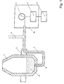
- the figure shows a container 1 for receiving the molten metal.
- This container 1 is mounted on pivot 2 in a frame, not shown.
- a gas supply 3 leads from a gas source, not shown, via a gas line 8 to a gas opening provided in the bottom region of the container 1. Gas can be supplied to the metal bath 9 via the gas feed 3.
- an unwinding device 4 on which an optical waveguide 7 is wound.
- One end of the optical waveguide 7 is connected to an optical sensor 5, which is connected to a signal evaluation 6.
- the unwinding device 4 and the optical detector 5 may be housed in a heat-protective housing 10.
- the optical waveguide 7 is introduced into the metal bath through the gas line 8, which is supplied with gas by means of the gas feed 3.
- the reaching into the metal bath 9 end of the optical waveguide 7 receives the radiation of the molten metal and passes it via the optical waveguide 7 to the optical sensor 5. There, the optical signals are converted into electronic signals that can be further processed by the signal evaluation 6, to determine the temperature of the metal in the metal bath 9. Since the temperature of the molten metal leads to the melting of the immersed end of the optical waveguide, the optical waveguide must be tracked. This is done by means of the gas flowing through the gas inlet 3 and the gas line 8.
Landscapes
- Physics & Mathematics (AREA)
- General Physics & Mathematics (AREA)
- Spectroscopy & Molecular Physics (AREA)
- Radiation Pyrometers (AREA)
- Carbon Steel Or Casting Steel Manufacturing (AREA)
- Manufacture And Refinement Of Metals (AREA)
Priority Applications (2)
| Application Number | Priority Date | Filing Date | Title |
|---|---|---|---|
| RS20170730A RS56309B1 (sr) | 2005-12-21 | 2006-12-13 | Konvertor sa sudom za prihvat rastopljenog metala i mernim uređajem za optičko određivanje temperature rastopljenog metala i postupak za određivanje temperature u takvom konvertoru |
| PL06829582T PL1966573T3 (pl) | 2005-12-21 | 2006-12-13 | Konwertor ze zbiornikiem do umieszczania stopionego metalu i urządzeniem pomiarowym do optycznego określania temperatury stopionego metalu i sposób określania temperatury w tego rodzaju konwertorze |
Applications Claiming Priority (2)
| Application Number | Priority Date | Filing Date | Title |
|---|---|---|---|
| DE102005061675A DE102005061675B3 (de) | 2005-12-21 | 2005-12-21 | Konverter mit einem Behälter zur Aufnahme geschmolzenen Metalls und einer Messvorrichtung zur optischen Temperaturbestimmung des geschmolzenen Metalls |
| PCT/EP2006/012014 WO2007079894A1 (de) | 2005-12-21 | 2006-12-13 | Konverter mit einem behälter zur aufnahme geschmolzenen metalls und einer messvorrichtung zur optischen temperaturbestimmung des geschmolzenen metalls sowie verfahren zur temperaturbestimmung in einem derartigen konverter |
Publications (2)
| Publication Number | Publication Date |
|---|---|
| EP1966573A1 EP1966573A1 (de) | 2008-09-10 |
| EP1966573B1 true EP1966573B1 (de) | 2017-06-28 |
Family
ID=37857188
Family Applications (1)
| Application Number | Title | Priority Date | Filing Date |
|---|---|---|---|
| EP06829582.3A Active EP1966573B1 (de) | 2005-12-21 | 2006-12-13 | Konverter mit einem behälter zur aufnahme geschmolzenen metalls und einer messvorrichtung zur optischen temperaturbestimmung des geschmolzenen metalls sowie verfahren zur temperaturbestimmung in einem derartigen konverter |
Country Status (8)
| Country | Link |
|---|---|
| US (1) | US8038344B2 (pl) |
| EP (1) | EP1966573B1 (pl) |
| KR (1) | KR101246279B1 (pl) |
| DE (1) | DE102005061675B3 (pl) |
| ES (1) | ES2634532T3 (pl) |
| PL (1) | PL1966573T3 (pl) |
| RS (1) | RS56309B1 (pl) |
| WO (1) | WO2007079894A1 (pl) |
Families Citing this family (19)
| Publication number | Priority date | Publication date | Assignee | Title |
|---|---|---|---|---|
| DE102010025562A1 (de) | 2010-02-18 | 2011-08-18 | SMS Siemag AG, 40237 | Injektorkühlblock zur Halterung mindestens eines Injektors |
| DE102010035411A1 (de) | 2010-08-25 | 2012-03-01 | Sms Siemag Ag | Verfahren zur Temperaturkontrolle des Metallbades während des Blasprozesses in einem Konverter |
| DE102011088127A1 (de) | 2011-06-07 | 2012-12-13 | Sms Siemag Ag | Strangführungssegment einer Strangführung einer Stranggießanlage und Verfahren zum Betreiben eines Strangführungssegments |
| DE102011085932A1 (de) | 2011-06-07 | 2012-12-13 | Sms Siemag Ag | Verfahren zum Regeln der Höhe des Gießspiegels in einer Kokille einer Stranggießanlage |
| EP2574601A1 (en) * | 2011-09-30 | 2013-04-03 | Rockwool International A/S | A method and an apparatus for measuring temperature of a fluid stream |
| DE102012201501B4 (de) | 2012-02-02 | 2015-11-12 | Ignatios Giannelis | Vorrichtung zur Bestimmung der Temperatur einer Schmelze |
| WO2014122532A2 (en) * | 2013-02-08 | 2014-08-14 | Jyoti Goda | Apparatus and methods for continuous temperature measurement of molten metals |
| DE102014012698B8 (de) | 2014-09-01 | 2016-07-14 | Minkon GmbH | Messvorrichtung zur optischen Temperaturbestimmung eines geschmolzenen Metalls |
| DE102014012697B4 (de) * | 2014-09-01 | 2016-06-09 | Minkon GmbH | Verfahren zur optischen Temperaturbestimmung eines geschmolzenen Metalls sowie Abspulvorrichtung zur Durchführung eines solchen Verfahrens |
| CN105865633A (zh) * | 2016-05-19 | 2016-08-17 | 田乃良 | 一种热传导和辐射的浮动跟踪测温方法 |
| PL3290881T3 (pl) | 2016-09-01 | 2020-01-31 | Heraeus Electro-Nite International N.V. | Sposób wprowadzania przewodu z rdzeniem światłowodowym i układ zanurzeniowy umożliwiający przeprowadzenie sposobu |
| DE102016010729A1 (de) | 2016-09-07 | 2018-03-08 | Minkon GmbH | Verfahren und Vorrichtung zur optischen Temperaturbestimmung eines geschmolzenen Materials sowie Verwendung eines Hohlraums bei der optischen Temperaturbestimmung eines geschmolzenen Materials |
| GB2558223B (en) * | 2016-12-22 | 2021-03-31 | Heraeus Electro Nite Int | Method for measuring a temperature of a molten metal bath |
| DE102018000615A1 (de) * | 2018-01-26 | 2019-08-01 | Minkon GmbH | Verwendung eines Lichtwellenleiters zur optischen Messung der Temperatur einer Hochtemperaturschmelze |
| CN109676435B (zh) * | 2019-02-15 | 2021-11-26 | 山东大学 | 一种铣削温度测试装置、系统及方法 |
| EP3929548A1 (en) * | 2020-06-22 | 2021-12-29 | Heraeus Electro-Nite International N.V. | Device and method for measuring a temperature of a molten metal |
| EP4009019B1 (en) * | 2020-12-02 | 2024-09-11 | Heraeus Electro-Nite International N.V. | Method and system for determining a temperature value of a molten metal bath |
| EP4009020A1 (en) * | 2020-12-02 | 2022-06-08 | Heraeus Electro-Nite International N.V. | Method and system for determining a series of temperature values of a molten metal bath |
| ES2997486T3 (en) | 2021-08-26 | 2025-02-17 | Heraeus Electro Nite Int | Measuring apparatus and method for measuring the temperature of a molten metal bath with an optical device |
Family Cites Families (9)
| Publication number | Priority date | Publication date | Assignee | Title |
|---|---|---|---|---|
| DE3117604A1 (de) * | 1981-05-05 | 1983-01-05 | Chemie-Werk Weinsheim Gmbh, 6520 Worms | "mehrschichtiges flaechenhaftes aussteifungsteil" |
| KR0134654B1 (ko) | 1993-10-05 | 1998-04-20 | 이요시 슌키치 | 광파이버를 사용한 온도측정장치 및 방법 |
| EP0802401A4 (en) | 1995-11-02 | 2000-07-12 | Mitsubishi Materials Corp | TEMPERATURE MEASURING METHOD, TEMPERATURE CONTROL METHOD AND TEMPERATURE MEASURING DEVICE FOR A HIGH TEMPERATURE MELT |
| DE69722305T2 (de) | 1996-04-09 | 2004-04-01 | Nkk Corp. | Vorrichtung zum Messen der Temperatur von geschmolzenem Metall |
| CN1116593C (zh) * | 2000-07-12 | 2003-07-30 | 东北大学 | 钢水温度连续测量方法和测温管 |
| ES2466766T3 (es) | 2001-07-27 | 2014-06-11 | Nippon Steel & Sumitomo Metal Corporation | Instrumento para medir la temperatura de un metal fundido |
| DE10331125B3 (de) * | 2003-07-09 | 2004-09-16 | Heraeus Electro-Nite International N.V. | Verfahren zum Abgleichen und Messen in Schmelzen mittels optischer Fasern sowie Vorrichtung dazu und deren Verwendung |
| DE10331124B3 (de) * | 2003-07-09 | 2005-02-17 | Heraeus Electro-Nite International N.V. | Verfahren und Vorrichtung zum Messen der Abkühlkurve von Schmelzenproben und/oder der Aufheizkurve von Schmelzenproben sowie deren Verwendung |
| GB2438214A (en) * | 2006-05-19 | 2007-11-21 | Heraeus Electro Nite Int | Measuring a parameter of a molten bath |
-
2005
- 2005-12-21 DE DE102005061675A patent/DE102005061675B3/de not_active Expired - Fee Related
-
2006
- 2006-12-13 RS RS20170730A patent/RS56309B1/sr unknown
- 2006-12-13 PL PL06829582T patent/PL1966573T3/pl unknown
- 2006-12-13 ES ES06829582.3T patent/ES2634532T3/es active Active
- 2006-12-13 US US12/158,448 patent/US8038344B2/en not_active Expired - Fee Related
- 2006-12-13 EP EP06829582.3A patent/EP1966573B1/de active Active
- 2006-12-13 WO PCT/EP2006/012014 patent/WO2007079894A1/de not_active Ceased
- 2006-12-13 KR KR1020087015324A patent/KR101246279B1/ko not_active Expired - Fee Related
Also Published As
| Publication number | Publication date |
|---|---|
| US20090074028A1 (en) | 2009-03-19 |
| DE102005061675B3 (de) | 2007-07-26 |
| EP1966573A1 (de) | 2008-09-10 |
| PL1966573T3 (pl) | 2017-10-31 |
| KR101246279B1 (ko) | 2013-03-21 |
| KR20080077644A (ko) | 2008-08-25 |
| ES2634532T3 (es) | 2017-09-28 |
| WO2007079894A1 (de) | 2007-07-19 |
| US8038344B2 (en) | 2011-10-18 |
| RS56309B1 (sr) | 2017-12-29 |
Similar Documents
| Publication | Publication Date | Title |
|---|---|---|
| EP1966573B1 (de) | Konverter mit einem behälter zur aufnahme geschmolzenen metalls und einer messvorrichtung zur optischen temperaturbestimmung des geschmolzenen metalls sowie verfahren zur temperaturbestimmung in einem derartigen konverter | |
| EP2287581B1 (de) | Verfahren und Vorrichtung zur kontaktlosen Ermittlung einer Temperatur T einer Metallschmelze | |
| DE102009059780B4 (de) | Einwurfsonde | |
| EP3605055A1 (de) | Probennehmer und verfahren zur probenentnahme | |
| DE60226261T2 (de) | Einrichtung und verfahren zur diskreten und kontinuierlichen messung der temperatur von geschmolzenem metall in einem ofen oder behälter für seine herstellung oder behandlung | |
| EP3189316B1 (de) | Verfahren zur systeminternen kalibrierung einer messvorrichtung zur optischen temperaturbestimmung eines geschmolzenen mettals | |
| EP0962801B1 (de) | Vorrichtung zur Herstellung eines optischen Kabels | |
| DE202005020851U1 (de) | Konverter mit einem Behälter zur Aufnahme geschmolzenen Metalls und einer Meßvorrichtung zur optischen Temperaturbestimmung des geschmolzenen Metalls | |
| EP3743700B1 (de) | Verwendung eines lichtwellenleiters zur optischen messung der temperatur einer hochtemperaturschmelze und vorrichtung dafür | |
| EP0364825B1 (de) | Vorrichtung zur diskontinuierlichen Messdatenerfassung der Schmelze | |
| DE10359447B4 (de) | Eintauchsensor | |
| AT410031B (de) | Einrichtung zur aufnahme und weiterleitung elektromagnetischer wellen, die von einer materialprobe ausgesendet werden | |
| EP2694691A1 (de) | Verfahren zum betrieb mindestens einer überschalldüse in einem metallurgischen gefäss, verfahren zur ermittlung eines druckverlusts, sowie system zum ermitteln von betriebsparametern mindestens einer überschalldüse | |
| EP2423674B1 (de) | Verfahren zur spektroskopischen Temperatur- und Analysebestimmung von flüssigen Metallbädern in metallurgischen Gefäßen, insbesondere Konvertern | |
| DE10352628A1 (de) | Verfahren und Einrichtung zum Bestimmen der Schmelzbadhöhe von aufeinanderfolgenden Roheisen-Chargen in einem Elektrolichtbogen-Ofen | |
| EP1617195A2 (de) | Führungseinrichtung für Signalleitungen, Vorrichtung zum Messen von Temperaturen und/oder Konzentrationen sowie Verwendung | |
| DE102004004241B3 (de) | Handlanze und Messvorrichtung mit Handlanze | |
| KR100845040B1 (ko) | 다트 투입기를 이용한 용강 샘플링 및 측온 장치 | |
| DE102013113708B3 (de) | Vorrichtung zur Beobachtung eines Bereichs eines heißen Metallbandes und/oder Schmelzbades in einem Bandbehandlungsprozess | |
| EP2492655B1 (de) | Messgerät zur Messung von Parametern in Schmelzen | |
| EP3649418A1 (de) | Führen einer sonde | |
| EP2136172A1 (de) | Lichtbogenofen | |
| DE102005043778A1 (de) | Vorrichtung und Verfahren zur Druckmessung | |
| AT517889A1 (de) | Erfassung einer Gießspiegelhöhe in einer Kokille | |
| WO2012022514A1 (de) | Verfahren zum betrieb einer metallurgischen vorrichtung, signalverarbeitungseinrichtung und metallurgische vorrichtung |
Legal Events
| Date | Code | Title | Description |
|---|---|---|---|
| PUAI | Public reference made under article 153(3) epc to a published international application that has entered the european phase |
Free format text: ORIGINAL CODE: 0009012 |
|
| 17P | Request for examination filed |
Effective date: 20080721 |
|
| AK | Designated contracting states |
Kind code of ref document: A1 Designated state(s): AT BE BG CH CY CZ DE DK EE ES FI FR GB GR HU IE IS IT LI LT LU LV MC NL PL PT RO SE SI SK TR |
|
| AX | Request for extension of the european patent |
Extension state: RS |
|
| 17Q | First examination report despatched |
Effective date: 20090416 |
|
| RAX | Requested extension states of the european patent have changed |
Extension state: RS Payment date: 20080721 |
|
| REG | Reference to a national code |
Ref country code: DE Ref legal event code: R079 Ref document number: 502006015561 Country of ref document: DE Free format text: PREVIOUS MAIN CLASS: G01J0005040000 Ipc: G01J0005000000 |
|
| GRAP | Despatch of communication of intention to grant a patent |
Free format text: ORIGINAL CODE: EPIDOSNIGR1 |
|
| RIC1 | Information provided on ipc code assigned before grant |
Ipc: G01J 5/04 20060101ALI20160810BHEP Ipc: G01J 5/00 20060101AFI20160810BHEP Ipc: G01J 5/08 20060101ALI20160810BHEP Ipc: G01J 5/02 20060101ALI20160810BHEP |
|
| INTG | Intention to grant announced |
Effective date: 20160913 |
|
| GRAS | Grant fee paid |
Free format text: ORIGINAL CODE: EPIDOSNIGR3 |
|
| GRAA | (expected) grant |
Free format text: ORIGINAL CODE: 0009210 |
|
| RAP1 | Party data changed (applicant data changed or rights of an application transferred) |
Owner name: MINKON GMBH |
|
| AK | Designated contracting states |
Kind code of ref document: B1 Designated state(s): AT BE BG CH CY CZ DE DK EE ES FI FR GB GR HU IE IS IT LI LT LU LV MC NL PL PT RO SE SI SK TR |
|
| AX | Request for extension of the european patent |
Extension state: RS |
|
| REG | Reference to a national code |
Ref country code: GB Ref legal event code: FG4D Free format text: NOT ENGLISH |
|
| REG | Reference to a national code |
Ref country code: CH Ref legal event code: EP |
|
| REG | Reference to a national code |
Ref country code: AT Ref legal event code: REF Ref document number: 905292 Country of ref document: AT Kind code of ref document: T Effective date: 20170715 |
|
| REG | Reference to a national code |
Ref country code: RO Ref legal event code: EPE |
|
| REG | Reference to a national code |
Ref country code: IE Ref legal event code: FG4D Free format text: LANGUAGE OF EP DOCUMENT: GERMAN |
|
| REG | Reference to a national code |
Ref country code: NL Ref legal event code: FP |
|
| REG | Reference to a national code |
Ref country code: DE Ref legal event code: R096 Ref document number: 502006015561 Country of ref document: DE |
|
| REG | Reference to a national code |
Ref country code: SE Ref legal event code: TRGR |
|
| REG | Reference to a national code |
Ref country code: CH Ref legal event code: NV Representative=s name: MICHELI AND CIE SA, CH |
|
| REG | Reference to a national code |
Ref country code: ES Ref legal event code: FG2A Ref document number: 2634532 Country of ref document: ES Kind code of ref document: T3 Effective date: 20170928 |
|
| PG25 | Lapsed in a contracting state [announced via postgrant information from national office to epo] |
Ref country code: LT Free format text: LAPSE BECAUSE OF FAILURE TO SUBMIT A TRANSLATION OF THE DESCRIPTION OR TO PAY THE FEE WITHIN THE PRESCRIBED TIME-LIMIT Effective date: 20170628 Ref country code: GR Free format text: LAPSE BECAUSE OF FAILURE TO SUBMIT A TRANSLATION OF THE DESCRIPTION OR TO PAY THE FEE WITHIN THE PRESCRIBED TIME-LIMIT Effective date: 20170929 |
|
| REG | Reference to a national code |
Ref country code: LT Ref legal event code: MG4D |
|
| PG25 | Lapsed in a contracting state [announced via postgrant information from national office to epo] |
Ref country code: LV Free format text: LAPSE BECAUSE OF FAILURE TO SUBMIT A TRANSLATION OF THE DESCRIPTION OR TO PAY THE FEE WITHIN THE PRESCRIBED TIME-LIMIT Effective date: 20170628 Ref country code: BG Free format text: LAPSE BECAUSE OF FAILURE TO SUBMIT A TRANSLATION OF THE DESCRIPTION OR TO PAY THE FEE WITHIN THE PRESCRIBED TIME-LIMIT Effective date: 20170928 |
|
| REG | Reference to a national code |
Ref country code: SK Ref legal event code: T3 Ref document number: E 24846 Country of ref document: SK |
|
| REG | Reference to a national code |
Ref country code: FR Ref legal event code: PLFP Year of fee payment: 12 |
|
| PG25 | Lapsed in a contracting state [announced via postgrant information from national office to epo] |
Ref country code: EE Free format text: LAPSE BECAUSE OF FAILURE TO SUBMIT A TRANSLATION OF THE DESCRIPTION OR TO PAY THE FEE WITHIN THE PRESCRIBED TIME-LIMIT Effective date: 20170628 |
|
| PG25 | Lapsed in a contracting state [announced via postgrant information from national office to epo] |
Ref country code: IS Free format text: LAPSE BECAUSE OF FAILURE TO SUBMIT A TRANSLATION OF THE DESCRIPTION OR TO PAY THE FEE WITHIN THE PRESCRIBED TIME-LIMIT Effective date: 20171028 |
|
| REG | Reference to a national code |
Ref country code: DE Ref legal event code: R097 Ref document number: 502006015561 Country of ref document: DE |
|
| PG25 | Lapsed in a contracting state [announced via postgrant information from national office to epo] |
Ref country code: DK Free format text: LAPSE BECAUSE OF FAILURE TO SUBMIT A TRANSLATION OF THE DESCRIPTION OR TO PAY THE FEE WITHIN THE PRESCRIBED TIME-LIMIT Effective date: 20170628 |
|
| PLBE | No opposition filed within time limit |
Free format text: ORIGINAL CODE: 0009261 |
|
| STAA | Information on the status of an ep patent application or granted ep patent |
Free format text: STATUS: NO OPPOSITION FILED WITHIN TIME LIMIT |
|
| 26N | No opposition filed |
Effective date: 20180329 |
|
| PG25 | Lapsed in a contracting state [announced via postgrant information from national office to epo] |
Ref country code: SI Free format text: LAPSE BECAUSE OF FAILURE TO SUBMIT A TRANSLATION OF THE DESCRIPTION OR TO PAY THE FEE WITHIN THE PRESCRIBED TIME-LIMIT Effective date: 20170628 |
|
| REG | Reference to a national code |
Ref country code: IE Ref legal event code: MM4A |
|
| PG25 | Lapsed in a contracting state [announced via postgrant information from national office to epo] |
Ref country code: LU Free format text: LAPSE BECAUSE OF NON-PAYMENT OF DUE FEES Effective date: 20171213 |
|
| PG25 | Lapsed in a contracting state [announced via postgrant information from national office to epo] |
Ref country code: IE Free format text: LAPSE BECAUSE OF NON-PAYMENT OF DUE FEES Effective date: 20171213 |
|
| PG25 | Lapsed in a contracting state [announced via postgrant information from national office to epo] |
Ref country code: HU Free format text: LAPSE BECAUSE OF FAILURE TO SUBMIT A TRANSLATION OF THE DESCRIPTION OR TO PAY THE FEE WITHIN THE PRESCRIBED TIME-LIMIT; INVALID AB INITIO Effective date: 20061213 Ref country code: MC Free format text: LAPSE BECAUSE OF FAILURE TO SUBMIT A TRANSLATION OF THE DESCRIPTION OR TO PAY THE FEE WITHIN THE PRESCRIBED TIME-LIMIT Effective date: 20170628 |
|
| PG25 | Lapsed in a contracting state [announced via postgrant information from national office to epo] |
Ref country code: CY Free format text: LAPSE BECAUSE OF NON-PAYMENT OF DUE FEES Effective date: 20170628 |
|
| PG25 | Lapsed in a contracting state [announced via postgrant information from national office to epo] |
Ref country code: PT Free format text: LAPSE BECAUSE OF FAILURE TO SUBMIT A TRANSLATION OF THE DESCRIPTION OR TO PAY THE FEE WITHIN THE PRESCRIBED TIME-LIMIT Effective date: 20170628 |
|
| PGFP | Annual fee paid to national office [announced via postgrant information from national office to epo] |
Ref country code: SK Payment date: 20221201 Year of fee payment: 17 Ref country code: RO Payment date: 20221206 Year of fee payment: 17 Ref country code: CZ Payment date: 20221201 Year of fee payment: 17 |
|
| PGFP | Annual fee paid to national office [announced via postgrant information from national office to epo] |
Ref country code: PL Payment date: 20221206 Year of fee payment: 17 |
|
| PGFP | Annual fee paid to national office [announced via postgrant information from national office to epo] |
Ref country code: TR Payment date: 20221209 Year of fee payment: 17 Ref country code: FR Payment date: 20230124 Year of fee payment: 17 Ref country code: FI Payment date: 20230125 Year of fee payment: 17 Ref country code: ES Payment date: 20230131 Year of fee payment: 17 Ref country code: CH Payment date: 20230222 Year of fee payment: 17 Ref country code: AT Payment date: 20230125 Year of fee payment: 17 |
|
| PGFP | Annual fee paid to national office [announced via postgrant information from national office to epo] |
Ref country code: SE Payment date: 20230124 Year of fee payment: 17 Ref country code: IT Payment date: 20230125 Year of fee payment: 17 Ref country code: GB Payment date: 20230124 Year of fee payment: 17 Ref country code: DE Payment date: 20230119 Year of fee payment: 17 Ref country code: BE Payment date: 20230125 Year of fee payment: 17 |
|
| PGFP | Annual fee paid to national office [announced via postgrant information from national office to epo] |
Ref country code: NL Payment date: 20230125 Year of fee payment: 17 |
|
| P01 | Opt-out of the competence of the unified patent court (upc) registered |
Effective date: 20230526 |
|
| REG | Reference to a national code |
Ref country code: DE Ref legal event code: R119 Ref document number: 502006015561 Country of ref document: DE |
|
| PG25 | Lapsed in a contracting state [announced via postgrant information from national office to epo] |
Ref country code: CZ Free format text: LAPSE BECAUSE OF NON-PAYMENT OF DUE FEES Effective date: 20231213 |
|
| REG | Reference to a national code |
Ref country code: SK Ref legal event code: MM4A Ref document number: E 24846 Country of ref document: SK Effective date: 20231213 |
|
| REG | Reference to a national code |
Ref country code: SE Ref legal event code: EUG |
|
| PG25 | Lapsed in a contracting state [announced via postgrant information from national office to epo] |
Ref country code: RO Free format text: LAPSE BECAUSE OF NON-PAYMENT OF DUE FEES Effective date: 20231213 Ref country code: FI Free format text: LAPSE BECAUSE OF NON-PAYMENT OF DUE FEES Effective date: 20231213 Ref country code: CZ Free format text: LAPSE BECAUSE OF NON-PAYMENT OF DUE FEES Effective date: 20231213 |
|
| REG | Reference to a national code |
Ref country code: CH Ref legal event code: PL |
|
| REG | Reference to a national code |
Ref country code: NL Ref legal event code: MM Effective date: 20240101 |
|
| REG | Reference to a national code |
Ref country code: AT Ref legal event code: MM01 Ref document number: 905292 Country of ref document: AT Kind code of ref document: T Effective date: 20231213 |
|
| GBPC | Gb: european patent ceased through non-payment of renewal fee |
Effective date: 20231213 |
|
| REG | Reference to a national code |
Ref country code: BE Ref legal event code: MM Effective date: 20231231 |
|
| PG25 | Lapsed in a contracting state [announced via postgrant information from national office to epo] |
Ref country code: NL Free format text: LAPSE BECAUSE OF NON-PAYMENT OF DUE FEES Effective date: 20240101 |
|
| PG25 | Lapsed in a contracting state [announced via postgrant information from national office to epo] |
Ref country code: NL Free format text: LAPSE BECAUSE OF NON-PAYMENT OF DUE FEES Effective date: 20240101 |
|
| PG25 | Lapsed in a contracting state [announced via postgrant information from national office to epo] |
Ref country code: DE Free format text: LAPSE BECAUSE OF NON-PAYMENT OF DUE FEES Effective date: 20240702 |
|
| PG25 | Lapsed in a contracting state [announced via postgrant information from national office to epo] |
Ref country code: GB Free format text: LAPSE BECAUSE OF NON-PAYMENT OF DUE FEES Effective date: 20231213 |
|
| PG25 | Lapsed in a contracting state [announced via postgrant information from national office to epo] |
Ref country code: BE Free format text: LAPSE BECAUSE OF NON-PAYMENT OF DUE FEES Effective date: 20231231 |
|
| PG25 | Lapsed in a contracting state [announced via postgrant information from national office to epo] |
Ref country code: FR Free format text: LAPSE BECAUSE OF NON-PAYMENT OF DUE FEES Effective date: 20231231 |
|
| PG25 | Lapsed in a contracting state [announced via postgrant information from national office to epo] |
Ref country code: CH Free format text: LAPSE BECAUSE OF NON-PAYMENT OF DUE FEES Effective date: 20231231 |
|
| PG25 | Lapsed in a contracting state [announced via postgrant information from national office to epo] |
Ref country code: AT Free format text: LAPSE BECAUSE OF NON-PAYMENT OF DUE FEES Effective date: 20231213 |
|
| PG25 | Lapsed in a contracting state [announced via postgrant information from national office to epo] |
Ref country code: SK Free format text: LAPSE BECAUSE OF NON-PAYMENT OF DUE FEES Effective date: 20231213 |
|
| PG25 | Lapsed in a contracting state [announced via postgrant information from national office to epo] |
Ref country code: SK Free format text: LAPSE BECAUSE OF NON-PAYMENT OF DUE FEES Effective date: 20231213 Ref country code: GB Free format text: LAPSE BECAUSE OF NON-PAYMENT OF DUE FEES Effective date: 20231213 Ref country code: FR Free format text: LAPSE BECAUSE OF NON-PAYMENT OF DUE FEES Effective date: 20231231 Ref country code: DE Free format text: LAPSE BECAUSE OF NON-PAYMENT OF DUE FEES Effective date: 20240702 Ref country code: CH Free format text: LAPSE BECAUSE OF NON-PAYMENT OF DUE FEES Effective date: 20231231 Ref country code: BE Free format text: LAPSE BECAUSE OF NON-PAYMENT OF DUE FEES Effective date: 20231231 Ref country code: AT Free format text: LAPSE BECAUSE OF NON-PAYMENT OF DUE FEES Effective date: 20231213 |
|
| REG | Reference to a national code |
Ref country code: ES Ref legal event code: FD2A Effective date: 20250129 |
|
| PG25 | Lapsed in a contracting state [announced via postgrant information from national office to epo] |
Ref country code: ES Free format text: LAPSE BECAUSE OF NON-PAYMENT OF DUE FEES Effective date: 20231214 |
|
| PG25 | Lapsed in a contracting state [announced via postgrant information from national office to epo] |
Ref country code: PL Free format text: LAPSE BECAUSE OF NON-PAYMENT OF DUE FEES Effective date: 20231213 |
|
| PG25 | Lapsed in a contracting state [announced via postgrant information from national office to epo] |
Ref country code: IT Free format text: LAPSE BECAUSE OF NON-PAYMENT OF DUE FEES Effective date: 20231213 |
|
| PG25 | Lapsed in a contracting state [announced via postgrant information from national office to epo] |
Ref country code: SE Free format text: LAPSE BECAUSE OF NON-PAYMENT OF DUE FEES Effective date: 20231214 |