EP1966573B1 - Converter with a container for receiving molten metal and with a measurement device for the optical temperature determination of the molten metal, and method for the temperature determination in such a converter - Google Patents
Converter with a container for receiving molten metal and with a measurement device for the optical temperature determination of the molten metal, and method for the temperature determination in such a converter Download PDFInfo
- Publication number
- EP1966573B1 EP1966573B1 EP06829582.3A EP06829582A EP1966573B1 EP 1966573 B1 EP1966573 B1 EP 1966573B1 EP 06829582 A EP06829582 A EP 06829582A EP 1966573 B1 EP1966573 B1 EP 1966573B1
- Authority
- EP
- European Patent Office
- Prior art keywords
- light wave
- fluid
- wave conductor
- container
- molten metal
- Prior art date
- Legal status (The legal status is an assumption and is not a legal conclusion. Google has not performed a legal analysis and makes no representation as to the accuracy of the status listed.)
- Active
Links
- 230000003287 optical effect Effects 0.000 title claims description 96
- 239000002184 metal Substances 0.000 title claims description 71
- 229910052751 metal Inorganic materials 0.000 title claims description 71
- 238000000034 method Methods 0.000 title claims description 18
- 238000005259 measurement Methods 0.000 title claims description 11
- 239000007789 gas Substances 0.000 claims description 58
- 239000012530 fluid Substances 0.000 claims description 46
- 230000005670 electromagnetic radiation Effects 0.000 claims description 20
- 238000004458 analytical method Methods 0.000 claims description 9
- QVGXLLKOCUKJST-UHFFFAOYSA-N atomic oxygen Chemical compound [O] QVGXLLKOCUKJST-UHFFFAOYSA-N 0.000 claims description 7
- 238000009529 body temperature measurement Methods 0.000 claims description 7
- 239000001301 oxygen Substances 0.000 claims description 7
- 229910052760 oxygen Inorganic materials 0.000 claims description 7
- 230000005540 biological transmission Effects 0.000 claims description 3
- 239000000203 mixture Substances 0.000 claims description 3
- 239000004020 conductor Substances 0.000 claims 22
- 230000032258 transport Effects 0.000 description 35
- 239000013307 optical fiber Substances 0.000 description 17
- 229910000831 Steel Inorganic materials 0.000 description 6
- 239000010959 steel Substances 0.000 description 6
- 238000007664 blowing Methods 0.000 description 5
- 229910000805 Pig iron Inorganic materials 0.000 description 3
- XKRFYHLGVUSROY-UHFFFAOYSA-N Argon Chemical compound [Ar] XKRFYHLGVUSROY-UHFFFAOYSA-N 0.000 description 2
- IJGRMHOSHXDMSA-UHFFFAOYSA-N Atomic nitrogen Chemical compound N#N IJGRMHOSHXDMSA-UHFFFAOYSA-N 0.000 description 2
- 230000001419 dependent effect Effects 0.000 description 2
- 238000011156 evaluation Methods 0.000 description 2
- 238000007710 freezing Methods 0.000 description 2
- 230000008014 freezing Effects 0.000 description 2
- 238000011065 in-situ storage Methods 0.000 description 2
- 238000002844 melting Methods 0.000 description 2
- 230000008018 melting Effects 0.000 description 2
- 239000002680 soil gas Substances 0.000 description 2
- 229910001341 Crude steel Inorganic materials 0.000 description 1
- 238000012369 In process control Methods 0.000 description 1
- 229910052786 argon Inorganic materials 0.000 description 1
- 238000009530 blood pressure measurement Methods 0.000 description 1
- 238000006243 chemical reaction Methods 0.000 description 1
- 238000002485 combustion reaction Methods 0.000 description 1
- 238000004891 communication Methods 0.000 description 1
- 238000001816 cooling Methods 0.000 description 1
- 238000012937 correction Methods 0.000 description 1
- 230000007850 degeneration Effects 0.000 description 1
- 230000000694 effects Effects 0.000 description 1
- 238000010891 electric arc Methods 0.000 description 1
- 238000005516 engineering process Methods 0.000 description 1
- 230000007613 environmental effect Effects 0.000 description 1
- 239000000835 fiber Substances 0.000 description 1
- 238000010965 in-process control Methods 0.000 description 1
- 239000011261 inert gas Substances 0.000 description 1
- 238000003780 insertion Methods 0.000 description 1
- 230000037431 insertion Effects 0.000 description 1
- 238000009413 insulation Methods 0.000 description 1
- 229910001338 liquidmetal Inorganic materials 0.000 description 1
- 238000004519 manufacturing process Methods 0.000 description 1
- 239000000155 melt Substances 0.000 description 1
- 229910052757 nitrogen Inorganic materials 0.000 description 1
- 230000035515 penetration Effects 0.000 description 1
- 238000004886 process control Methods 0.000 description 1
- 238000010926 purge Methods 0.000 description 1
- 230000005855 radiation Effects 0.000 description 1
- 230000001105 regulatory effect Effects 0.000 description 1
- 238000009628 steelmaking Methods 0.000 description 1
- 238000012360 testing method Methods 0.000 description 1
Images
Classifications
-
- G—PHYSICS
- G01—MEASURING; TESTING
- G01J—MEASUREMENT OF INTENSITY, VELOCITY, SPECTRAL CONTENT, POLARISATION, PHASE OR PULSE CHARACTERISTICS OF INFRARED, VISIBLE OR ULTRAVIOLET LIGHT; COLORIMETRY; RADIATION PYROMETRY
- G01J5/00—Radiation pyrometry, e.g. infrared or optical thermometry
- G01J5/02—Constructional details
- G01J5/08—Optical arrangements
-
- G—PHYSICS
- G01—MEASURING; TESTING
- G01J—MEASUREMENT OF INTENSITY, VELOCITY, SPECTRAL CONTENT, POLARISATION, PHASE OR PULSE CHARACTERISTICS OF INFRARED, VISIBLE OR ULTRAVIOLET LIGHT; COLORIMETRY; RADIATION PYROMETRY
- G01J5/00—Radiation pyrometry, e.g. infrared or optical thermometry
- G01J5/0037—Radiation pyrometry, e.g. infrared or optical thermometry for sensing the heat emitted by liquids
- G01J5/004—Radiation pyrometry, e.g. infrared or optical thermometry for sensing the heat emitted by liquids by molten metals
-
- G—PHYSICS
- G01—MEASURING; TESTING
- G01J—MEASUREMENT OF INTENSITY, VELOCITY, SPECTRAL CONTENT, POLARISATION, PHASE OR PULSE CHARACTERISTICS OF INFRARED, VISIBLE OR ULTRAVIOLET LIGHT; COLORIMETRY; RADIATION PYROMETRY
- G01J5/00—Radiation pyrometry, e.g. infrared or optical thermometry
- G01J5/02—Constructional details
- G01J5/04—Casings
- G01J5/041—Mountings in enclosures or in a particular environment
- G01J5/042—High-temperature environment
-
- G—PHYSICS
- G01—MEASURING; TESTING
- G01J—MEASUREMENT OF INTENSITY, VELOCITY, SPECTRAL CONTENT, POLARISATION, PHASE OR PULSE CHARACTERISTICS OF INFRARED, VISIBLE OR ULTRAVIOLET LIGHT; COLORIMETRY; RADIATION PYROMETRY
- G01J5/00—Radiation pyrometry, e.g. infrared or optical thermometry
- G01J5/02—Constructional details
- G01J5/05—Means for preventing contamination of the components of the optical system; Means for preventing obstruction of the radiation path
- G01J5/051—Means for preventing contamination of the components of the optical system; Means for preventing obstruction of the radiation path using a gas purge
-
- G—PHYSICS
- G01—MEASURING; TESTING
- G01J—MEASUREMENT OF INTENSITY, VELOCITY, SPECTRAL CONTENT, POLARISATION, PHASE OR PULSE CHARACTERISTICS OF INFRARED, VISIBLE OR ULTRAVIOLET LIGHT; COLORIMETRY; RADIATION PYROMETRY
- G01J5/00—Radiation pyrometry, e.g. infrared or optical thermometry
- G01J5/02—Constructional details
- G01J5/08—Optical arrangements
- G01J5/0818—Waveguides
- G01J5/0821—Optical fibres
Definitions
- the invention relates to a converter with a container for receiving molten metal and a measuring device for the optical temperature determination of the molten metal and a method for determining temperature in such a converter.
- pig iron is usually converted into steel in an oxygen-blowing converter.
- an oxygen-blowing converter typically 150 t to 400 t of molten pig iron are poured into a large, crucible-shaped container (converter vessel) and converted into crude steel by blowing and / or blowing large amounts of oxygen.
- the temperature of the metal bath rises due to the combustion of the unwanted pig iron components.
- the essential target for a control is the steel bath temperature at the end of the converter process.
- the converter process is interrupted for temperature measurement and carried out a manual temperature measurement.
- measuring lances are introduced with end-mounted thermocouples in the molten metal.
- a converter with a container for receiving molten metal has a measuring device for the optical temperature determination of the molten metal, wherein a metal-coated optical waveguide is provided to guide electromagnetic radiation mimicked by the metal or the tip of the optical waveguide to an optical detector. Furthermore, in the converter described there, an optical detector for determining the temperature of the metal from an analysis of the electromagnetic radiation is known.
- the converter described there has a motor, are driven with the rollers. These rollers 13 engage the metal-clad optical fiber to apply transport forces to the optical fiber with which the metal clad optical fiber can be slid along a straight line into the container for receiving the molten metal.
- EP 0 646 778 The metal sheathed, pushed by the rollers optical waveguide in the straight line leading to the container line flows around a gas stream. The gas is flowed into the conduit to clear a nozzle at the end of the conduit through which the metal sheathed optical fiber is to enter the container of the converter.
- EP 0 646 778 A1 describes control means with which the gas flow is controlled. This control takes place as a function of the pressure in the line and a measured transport speed of the metal-clad optical waveguide. From these two informations should according to EP 0 646 778 A1 information about whether the nozzle is clogged.
- EP 0 646 778 A1 is the Metallummantelung of the optical waveguide, inter alia, therefore provided to the optical fiber itself to protect against the gas pressure of the surrounding gas, while the metal-clad optical fiber is pushed by the transport in the direction of the container of the converter.
- EP 0 802 401 A comparable procedure is off EP 0 802 401 in which also a metal-coated optical waveguide by means of a transport device, which may consist of two opposite rollers or from a drive of the coil on which the metal-clad optical fiber is wound, is moved. This mechanical drive exerts transport forces on the metal jacket of the optical waveguide and pushes them through a straight tube into the container of a converter.
- EP 0 646 778 A1 is in EP 0 802 401 A1 not intended to flow around the optical fiber during its transport through the conduit with gas.
- the line in which the metal-clad optical waveguide is transported is attached to a blowing nozzle of a converter and the metal-clad optical waveguide is guided by the mechanical conveying device through this nozzle into the container of the converter.
- the object of the invention is to propose a converter which allows a continuous optical temperature measurement of the molten metal with low measurement uncertainties, and to propose a method for determining the temperature of the molten metal in such a converter.
- the invention is based on the idea of supplying an optical waveguide to the molten metal, which is arranged in a fluid-flow line and is transported in the conduit with the aid of the fluid.
- the high temperatures cause the optical fiber to gradually melt at its end immersed in the molten metal or in close proximity to the molten metal.
- the inventively provided tracking of the optical waveguide by the caused by the fluid in the conduit transport causes a for receiving the of the Metal emitted or capable of emitting the representative electromagnetic radiation capable surface of the optical waveguide is always immersed in the molten metal or in the necessary for receiving or emitting the electromagnetic radiation proximity to the molten metal is located.
- the converter according to the invention has an optical detector for determining the temperature of the metal from an analysis of the electromagnetic radiation transmitted by the optical waveguide.
- This optical detector is arranged according to the invention spaced from the container in a region in which the ambient temperature is less than 150 ° C, more preferably less than 70 ° C and most preferably less than 50 ° C.
- a line leading the optical waveguide is provided, in which a transport of the optical waveguide takes place through a flowing fluid through the conduit, it is now possible to arrange the necessary for the analysis of the electromagnetic radiation optical detector at a significant distance from the container, namely in one Area in which the ambient temperature has fallen so low that it is not harmful to electronic switchgear.
- the optical detector is located farther than 5 meters from the converter vessel (container).
- the fluid-flow conduit disposed between the optical detector and the container may be a transport conduit provided separately for the supply of the optical fiber, which may also terminate above a free surface of the molten metal and bring the optical fiber there into or near the molten metal. to absorb the electromagnetic radiation emitted by the metal.
- the transport line may terminate at an opening provided in the wall of the container and supply the optical waveguide to the metal via this opening, wherein the fluid flowing in the conduit additionally has the advantage that it can at least partially prevent clogging of this opening.
- an already provided on the converter fluid conduit system is used as a conduit for the transport of the optical waveguide, such as the conduit system for supplying soil gas, for example consisting of purge gases such as nitrogen or argon or fresh gas such as oxygen or oxygen mixtures.
- the conduit system for supplying soil gas for example consisting of purge gases such as nitrogen or argon or fresh gas such as oxygen or oxygen mixtures.
- the transport line provided for the optical waveguide can be introduced as an additional line into an existing line, for example provided coaxially in the middle in a line which leads fluid to a fluid feed opening in the container, for example in a line with which bottom gas is guided to a bottom gas opening.
- This arrangement of the transport line in an existing line can also be done only in specific areas, for example in the field of refractory lining of a converter.
- fluid jacket is used for thermal insulation of the inner transport line through which the optical waveguide is guided.
- the invention is realized with a converter having a container for receiving molten metal, for example on an oxygen-blowing converter.
- the terms "converter” and “molten metal” used herein for simplicity and uniformity also include all those devices having a container for holding a molten medium, wherein the temperature of the molten medium due to analysis of the medium emitted electromagnetic radiation can be detected by an optical detector.
- the term “converter” may also include electric arc furnaces, melting pots or the like.
- the transport of the optical waveguide takes place essentially with the aid of the fluid flowing through the conduit.
- the optical waveguide be provided with surface properties that allow a particularly good transmission of the transport forces of the fluid to the optical waveguide, such as a special structuring of the surface of the optical waveguide.
- a soft, flexible optical waveguide is preferably used, as is known, for example, from communications technology. These allow it especially well, the light waveguide to transport corners, constrictions or arcs of the line system.
- a fluid for example oxygen, which is necessary in any case for the treatment of the molten metal is preferably used.
- gases such as inert gases.
- the converter has an optical waveguide supply.
- This may be a coiled optical fiber, one end of which is inserted into the molten metal via the fluid-flow conduit and the other end connected to the optical detector.
- other supplies such as a looped fiber optic cable or a ball, may be provided.
- the supply of the optical waveguide in the molten metal is preferably carried out at a constant conveying speed. For example, in the case of a G62.5 / 125 optical fiber having an outer diameter of 0.9 mm, it has been found convenient to flow the fluid through the conduit at a rate of 5 meters per second.
- the converter according to the invention has an unwinding device which unwinds the optical waveguide successively from a supply.
- Such unwinding devices may, for example, have two counter-rotating, preferably rubberized rollers, one of which, for example, is driven and transports the optical waveguide guided through the gap between the rollers. This transport can be continuous or discontinuous and in particular regulated.
- the unwinding device is arranged in a region in which the ambient temperature is less than 150 ° C, preferably less than 70 ° C and particularly preferably less than 50 ° C.
- an enclosure for the optical detector may be provided, wherein a possibly existing unwinding device may also be arranged in this enclosure.
- the housing protects the optical detector and the unwinding device from the harmful environmental influences, such as dirt.
- the housing 10 has an internal pressure during operation, which is the internal pressure of the subsequent gas line, in which the optical waveguide transported by means of the fluid is, corresponds. As a result, the transport of the optical waveguide is simplified by means of the fluid.
- the enclosure may be heat-protected, thus preventing the penetration of heat into the enclosure.
- Such enclosures can be used in particular if the optical detector and, for example, the unwinding device are to be protected particularly well from the effects of temperature despite the significantly lower ambient temperature.
- the operation of the system provides the converter with the purpose of passing the transport of other containers with molten metal past the converter according to the invention. This can lead to short-term increases in temperature, when such a container is guided past the optical detector.
- the heat-protected enclosure then prevents the optical detector located in an area with an average ambient temperature of less than 150 ° C from being damaged by such short-term temperature peaks.
- the heat-protected housing can also have an active cooling.
- the optical waveguide is guided at least in sections through a gas line, with which gas is introduced into the container for treating the molten metal, and transported with the aid of the gas.
- the optical waveguide is particularly preferably introduced into the gas line via an insertion opening in the gas line.
- This introduction opening is preferably arranged in the region of a gas source, from which gas is fed into the gas line.
- the source of gas is understood to mean any source from which gas is fed into a line system assigned only to the converter.
- the gas source may be, for example, the branch from a gas service network, where the gas for the individual converter is taken from the general operating line.
- Such branches from the operating network for the respective converter are often located at a sufficient distance from the container for receiving the molten metal of the converter in question, so that an optical detector arranged in this area or an unwinding device arranged in this area is arranged in a region the ambient temperature is less than 150 ° C. Therefore, it is advantageous to arrange the optical detector in the region of this branch.
- the invention proposed transporting the optical waveguide with the aid of the flowing fluid, the optical waveguide is reliably transported to the container despite the significant distance to the container itself.
- the converter has pins on which the container is pivotally suspended.
- the fluid-flow line can be passed through the pin, so that despite the pivotal movement of the container, a good supply of the optical waveguide to the container is possible.
- the object is further achieved by the method according to claim 8.
- Advantageous embodiments are specified in the dependent claims.
- the inventive method is carried out on a converter according to the invention.
- the optical waveguide is fed to the container and thereby transported at least in sections through the arranged between the optical detector and the container fluid-flow line with the aid of the fluid.
- the detector analyzes the electromagnetic radiation transmitted by the optical fiber from the molten metal to the detector to determine the temperature of the metal.
- the transport of the optical waveguide can be continuous or intermittent.
- the optical waveguide is supplied to the molten metal via a fluid opening of the container, wherein the container via this fluid opening and a further fluid is supplied, for example, a bottom gas.
- a further fluid is supplied, for example, a bottom gas.
- the optical waveguide is held in a not yet immersed position, and analyzed by the thus held optical waveguide to the detector electromagnetic radiation from the detector and / or the pressure profile of the other fluid, through the Fluid port is supplied to the container, measured.
- the transport of the thus held optical waveguide into the molten metal is only started when the measured value corresponds to a predetermined starting value (the measured values correspond to predetermined starting values).
- a particular problem when transporting the optical waveguide into the container through a fluid opening is the possibility of eventual Freezing of molten metal in the area of the fluid opening or otherwise adding the opening. It has been found that clogging of the fluid opening can be detected by observing the pressure profile of the fluid, for example the bottom gas, flowing in through the fluid opening into the container in addition to the fluid used for the transport of the optical waveguide. Alternatively or additionally, clogging can be determined by analyzing the electromagnetic radiation transmitted to the detector from the optical fiber held in the non-immersed position. It is possible to set thresholds or value ranges above or within which a transport can begin.
- the above-described test of the addition of the fluid opening is carried out in an intermittently carried out measurement particularly preferably before each new transport recording.
- the transport of the optical waveguide is also performed intermittently in intermittent measurement. Before each new measurement, the transport of the optical waveguide held in a not yet immersed position is only started when the measured value has undershot or exceeded a predefined threshold value (depending on how the threshold is defined) or within a predetermined value range lies.
- the transport of the optical waveguide held in a not yet immersed position is only started when the pressure value has fallen below a threshold value of the measured value (depending on how the threshold is defined ), or in a predetermined range of values and if at the same time a value resulting from the analysis of the electromagnetic radiation has undershot or exceeded a threshold value (depending on how the threshold is defined) or in a predetermined value Range of values is.
- a threshold value of the measured value depending on how the threshold is defined
- bottom gas is supplied to the molten metal via a bottom gas opening, and the composition of the bottom gas is enriched with oxygen for a period of time before and / or during the measurement.
- the bottom gas is enriched with 5% to 20% oxygen.
- a control of the enrichment can be provided. An input variable of this control can be the pressure curve of the Be soil gas. In this way, a freezing of the molten metal in the region of the bottom gas opening can be prevented, or a freeze can be melted.
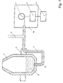
- the figure shows a container 1 for receiving the molten metal.
- This container 1 is mounted on pivot 2 in a frame, not shown.
- a gas supply 3 leads from a gas source, not shown, via a gas line 8 to a gas opening provided in the bottom region of the container 1. Gas can be supplied to the metal bath 9 via the gas feed 3.
- an unwinding device 4 on which an optical waveguide 7 is wound.
- One end of the optical waveguide 7 is connected to an optical sensor 5, which is connected to a signal evaluation 6.
- the unwinding device 4 and the optical detector 5 may be housed in a heat-protective housing 10.
- the optical waveguide 7 is introduced into the metal bath through the gas line 8, which is supplied with gas by means of the gas feed 3.
- the reaching into the metal bath 9 end of the optical waveguide 7 receives the radiation of the molten metal and passes it via the optical waveguide 7 to the optical sensor 5. There, the optical signals are converted into electronic signals that can be further processed by the signal evaluation 6, to determine the temperature of the metal in the metal bath 9. Since the temperature of the molten metal leads to the melting of the immersed end of the optical waveguide, the optical waveguide must be tracked. This is done by means of the gas flowing through the gas inlet 3 and the gas line 8.
Description
Die Erfindung betrifft einen Konverter mit einem Behälter zur Aufnahme geschmolzenen Metalls und einer Meßvorrichtung zur optischen Temperaturbestimmung des geschmolzenen Metalls sowie ein Verfahren zur Temperaturbestimmung in einem derartigen Konverter.The invention relates to a converter with a container for receiving molten metal and a measuring device for the optical temperature determination of the molten metal and a method for determining temperature in such a converter.
In der Stahlerzeugung wird Roheisen meist in einem Sauerstoffblaskonverter in Stahl umgewandelt. Hierzu werden typischerweise 150 t bis 400 t flüssigen Roheisens in einen großen, tiegelförmigen Behälter (Konvertergefäß) eingefüllt und durch Aufblasen und/oder Durchblasen großer Mengen Sauerstoffs in Rohstahl umgewandelt. Dabei steigt die Temperatur des Metallbades durch die Verbrennung der unerwünschten Roheisenbestandteile.In steelmaking, pig iron is usually converted into steel in an oxygen-blowing converter. For this purpose, typically 150 t to 400 t of molten pig iron are poured into a large, crucible-shaped container (converter vessel) and converted into crude steel by blowing and / or blowing large amounts of oxygen. The temperature of the metal bath rises due to the combustion of the unwanted pig iron components.
Die wesentliche Zielgröße für eine Regelung ist die Stahlbadtemperatur am Ende des Konverterprozesses. Üblicherweise wird zur Temperaturmessung der Konverterprozeß unterbrochen und eine manuelle Temperaturmessung durchgeführt. Hierzu werden beispielsweise Meßlanzen mit endseitig angebrachten Thermoelementen in das geschmolzene Metall eingeführt.The essential target for a control is the steel bath temperature at the end of the converter process. Usually, the converter process is interrupted for temperature measurement and carried out a manual temperature measurement. For this purpose, for example, measuring lances are introduced with end-mounted thermocouples in the molten metal.
Die für die Temperaturmessung und daraus abgeleitete Korrekturmaßnahmen benötigte Zeitspanne erschwert die Prozeßsteuerung und den Prozeßablauf. Deshalb sind Maßnahmen unternommen worden, eine kontinuierliche in situ Temperaturmessung während des Konverterprozesses durchzuführen, die zu einer wesentlichen Verbesserung der Prozeßführung und dadurch zu einer deutlichen Effizienzsteigerung der Stahlherstellung führen.The time required for the temperature measurement and the correction measures derived therefrom makes the process control and the process sequence more difficult. Therefore, measures have been taken to perform a continuous in situ temperature measurement during the converter process, which leads to a significant improvement in process control and thereby to a significant increase in efficiency of steel production.
Aus der Praxis ist es beispielsweise bekannt, zur kontinuierlichen in situ Temperaturmessung eine pyrometrische Analyse der vom Stahlbad ausgesandten elektromagnetischen Strahlung durchzuführen. So wird beispielsweise die Stahlbadoberfläche beobachtet. Bei diesem Verfahren führt ein stark schwankender Emissionsgrad des heterogenen und stark bewegten Badspiegels jedoch zu inakzeptablen Meßunsicherheiten. Ferner ist überlegt worden, in der feuerfesten Ausmauerung der Konverterwand Einbauten, wie beispielsweise Fenster, vorzusehen. Diese sind jedoch aufgrund der optischen Degenerierung durch die hohen Temperaturen, die typischerweise bis zu 1800°C betragen können, nachteilbehaftet. In der feuerfesten Ausmauerung vorgesehene Zugänge unterliegen wiederum einer starken mechanischen Beanspruchung durch Setzvorgänge, die die meist röhrenförmigen Zugänge zur Schmelze so stark deformieren, daß ein optischer Zugang zum Stahlbad entlang der Sichtlinie nicht mehr möglich ist.For example, it is known from practice to carry out a pyrometric analysis of the electromagnetic radiation emitted by the steel bath for continuous in situ temperature measurement. For example, the steel bath surface is observed. In this method, however, a strongly fluctuating emissivity of the heterogeneous and strongly moving bath level leads to unacceptable measurement uncertainties. It has also been considered to provide internals, such as windows, in the refractory lining of the converter wall. However, these are due to the optical degeneration due to the high temperatures, which may typically be up to 1800 ° C, disadvantageous. In addition, provided in the refractory lining accesses are subject to a strong mechanical stress by setting operations that deform the most tubular access to the melt so strong that an optical access to the steel bath along the line of sight is no longer possible.
Aus
Eine vergleichbare Vorgehensweise ist aus
Aus
Vor diesem Hintergrund liegt der Erfindung die Aufgabe zugrunde, einen Konverter vorzuschlagen, der eine kontinuierliche optische Temperaturmessung des geschmolzenen Metalls mit geringen Meßunsicherheiten erlaubt, und ein Verfahren zur Temperaturbestimmung des geschmolzenen Metalls in einem derartigen Konverter vorzuschlagen.Against this background, the object of the invention is to propose a converter which allows a continuous optical temperature measurement of the molten metal with low measurement uncertainties, and to propose a method for determining the temperature of the molten metal in such a converter.
Diese Aufgabe wird durch einen Konverter gemäß Anspruch 1 gelöst. Vorteilhafte Ausführungsformen sind in den abhängigen Ansprüchen angegeben.This object is achieved by a converter according to claim 1. Advantageous embodiments are given in the dependent claims.
Die Erfindung geht von dem Grundgedanken aus, dem geschmolzenen Metall einen Lichtwellenleiter zuzuführen, der in einer fluiddurchströmten Leitung angeordnet ist und in der Leitung mit Hilfe des Fluids transportiert wird.The invention is based on the idea of supplying an optical waveguide to the molten metal, which is arranged in a fluid-flow line and is transported in the conduit with the aid of the fluid.
Die hohen Temperaturen führen dazu, daß der Lichtwellenleiter an seinem in das geschmolzene Metall eingetauchten bzw. in unmittelbarer Nähe zu dem geschmolzenen Metall gebrachten Ende allmählich aufschmilzt. Die erfindungsgemäß vorgesehene Nachführung des Lichtwellenleiters durch den von dem Fluid in der Leitung hervorgerufenen Transport führt jedoch dazu, daß eine zur Aufnahme der von dem Metall emittierten oder zur Emission der repräsentativen elektromagnetischen Strahlung fähige Oberfläche des Lichtwellenleiters stets in das geschmolzene Metall eingetaucht bzw. in der zur Aufnahme oder Emission der elektromagnetischen Strahlung notwendigen Nähe zu dem geschmolzenen Metall befindlich ist.The high temperatures cause the optical fiber to gradually melt at its end immersed in the molten metal or in close proximity to the molten metal. However, the inventively provided tracking of the optical waveguide by the caused by the fluid in the conduit transport, however, causes a for receiving the of the Metal emitted or capable of emitting the representative electromagnetic radiation capable surface of the optical waveguide is always immersed in the molten metal or in the necessary for receiving or emitting the electromagnetic radiation proximity to the molten metal is located.
Der erfindungsgemäße Konverter weist einen optischen Detektor zur Bestimmung der Temperatur des Metalls aus einer Analyse der von dem Lichtwellenleiter weitergeleiteten elektromagnetischen Strahlung auf. Dieser optische Detektor ist erfindungsgemäß beabstandet von dem Behälter in einem Bereich angeordnet, in der die Umgebungstemperatur weniger als 150°C, insbesondere bevorzugt weniger als 70°C und ganz besonders bevorzugt weniger als 50°C beträgt.The converter according to the invention has an optical detector for determining the temperature of the metal from an analysis of the electromagnetic radiation transmitted by the optical waveguide. This optical detector is arranged according to the invention spaced from the container in a region in which the ambient temperature is less than 150 ° C, more preferably less than 70 ° C and most preferably less than 50 ° C.
Indem erfindungsgemäß eine den Lichtwellenleiter führende Leitung vorgesehen ist, in der ein Transport des Lichtwellenleiters durch ein durch die Leitung strömendes Fluid erfolgt, wird es erstmals möglich, den zur Analyse der elektromagnetischen Strahlung notwendigen optischen Detektor in deutlichem Abstand zu dem Behälter anzuordnen, nämlich in einem Bereich, in dem die Umgebungstemperatur so weit abgesunken ist, daß sie für elektronische Schaltanlagen nicht schädlich ist. Bei einem Sauerstoffblaskonverter wird der optische Detektor beispielsweise weiter als 5 Meter von dem Konvertergefäß (Behälter) entfernt angeordnet.By according to the invention, a line leading the optical waveguide is provided, in which a transport of the optical waveguide takes place through a flowing fluid through the conduit, it is now possible to arrange the necessary for the analysis of the electromagnetic radiation optical detector at a significant distance from the container, namely in one Area in which the ambient temperature has fallen so low that it is not harmful to electronic switchgear. For example, in an oxygen-bubble converter, the optical detector is located farther than 5 meters from the converter vessel (container).
Die zwischen dem optischen Detektor und dem Behälter angeordnete, fluiddurchströmte Leitung kann eine gesondert für die Zuführung des Lichtwellenleiters vorgesehene Transportleitung sein, die auch oberhalb einer freien Oberfläche des geschmolzenen Metalls enden kann und den Lichtwellenleiter dort in Kontakt oder in die Nähe des geschmolzenen Metalls bringt, um die von dem Metall emittierte elektromagnetische Strahlung aufzunehmen. Ebenso kann die Transportleitung an einer in der Wandung des Behälters vorgesehenen Öffnung enden und den Lichtwellenleiter dem Metall über diese Öffnung zuführen, wobei das in der Leitung strömende Fluid zusätzlich den Vorteil aufweist, daß es ein Zusetzen dieser Öffnung zumindest teilweise verhindern kann.The fluid-flow conduit disposed between the optical detector and the container may be a transport conduit provided separately for the supply of the optical fiber, which may also terminate above a free surface of the molten metal and bring the optical fiber there into or near the molten metal. to absorb the electromagnetic radiation emitted by the metal. Likewise, the transport line may terminate at an opening provided in the wall of the container and supply the optical waveguide to the metal via this opening, wherein the fluid flowing in the conduit additionally has the advantage that it can at least partially prevent clogging of this opening.
Alternativ und bevorzugt wird als Leitung für den Transport des Lichtwellenleiters ein bereits an dem Konverter vorgesehenes Fluid-Leitungssystem verwendet, wie beispielsweise das Leitungssystem für das Zuführen von Bodengas, beispielsweise bestehend aus Spülgasen wie Stickstoff oder Argon oder Frischgas wie Sauerstoff oder Sauerstoffgemischen. Damit ist es möglich, bestehende Konverter ohne große Umbaumaßnahmen in erfindungsgemäße Konverter umzurüsten. Ebenso ist eine Kombination aus einer speziell für den Lichtwellenleiter vorgesehene Transportleitung mit einem vorhandenen Leitungssystem möglich, beispielsweise wenn der Lichtwellenleiter zunächst in einem eigenen Transport-Leitungssystem transportiert wird und beispielsweise erst kurz vor der Bodengasöffnung eines Bodengassystems mit dem Bodengassystem verbunden wird, beispielsweise über ein T-Stück im Bereich der Bodengasöffnung des Konverters. Die für den Lichtwellenleiter vorgesehene Transportleitung kann als zusätzliche Leitung in eine bestehende Leitung eingebracht werden, beispielsweise koaxial mittig in einer Leitung vorgesehen sein, die Fluid zu einer Fluidzuführöffnung in dem Behälter führt, beispielsweise in einer Leitung, mit der Bodengas zu einer Bodengasöffnung geführt wird. Diese Anordnung der Transportleitung in einer bestehenden Leitung kann auch nur in speziellen Bereichen erfolgen, beispielsweise im Bereich der feuerfesten Ausmauerung eines Konverters. Bei einer Anordnung der Transportleitung in einer bestehenden Fluidleitung dient der außen um die Transportleitung strömende Fluidmantel zur thermischen Isolierung der inneren Transportleitung, durch die der Lichtwellenleiter geführt wird.Alternatively and preferably, an already provided on the converter fluid conduit system is used as a conduit for the transport of the optical waveguide, such as the conduit system for supplying soil gas, for example consisting of purge gases such as nitrogen or argon or fresh gas such as oxygen or oxygen mixtures. This makes it possible to convert existing converters without major Conversion measures to convert converter according to the invention. Likewise, a combination of a specially provided for the optical fiber transport line with an existing line system is possible, for example, when the optical fiber is first transported in a separate transport line system and, for example, is connected to the bottom gas system shortly before the bottom gas opening of a floor gas system, for example via a T. Piece in the area of the bottom gas opening of the converter. The transport line provided for the optical waveguide can be introduced as an additional line into an existing line, for example provided coaxially in the middle in a line which leads fluid to a fluid feed opening in the container, for example in a line with which bottom gas is guided to a bottom gas opening. This arrangement of the transport line in an existing line can also be done only in specific areas, for example in the field of refractory lining of a converter. In an arrangement of the transport line in an existing fluid line of the outside flowing around the transport line fluid jacket is used for thermal insulation of the inner transport line through which the optical waveguide is guided.
Die Erfindung wird mit einem Konverter mit einem Behälter zur Aufnahme geschmolzenen Metalls verwirklicht, beispielsweise an einem Sauerstoffblaskonverter. Die hier aus Gründen der Vereinfachung und Einheitlichkeit verwendeten Begriffe "Konverter" und "geschmolzenes Metall" schließen auch alle die Vorrichtungen ein, die einen Behälter zur Aufnahme eines geschmolzenen Mediums aufweisen, bei dem sich die Temperatur des geschmolzenen Mediums aufgrund einer Analyse der von dem Medium emittierten elektromagnetischen Strahlen durch einen optischen Detektor feststellen läßt. Beispielsweise kann der Begriff "Konverter" auch Elektrolichtbogenöfen, Schmelzpfannen oder dergleichen umfassen.The invention is realized with a converter having a container for receiving molten metal, for example on an oxygen-blowing converter. The terms "converter" and "molten metal" used herein for simplicity and uniformity also include all those devices having a container for holding a molten medium, wherein the temperature of the molten medium due to analysis of the medium emitted electromagnetic radiation can be detected by an optical detector. For example, the term "converter" may also include electric arc furnaces, melting pots or the like.
Der Transport des Lichtwellenleiters erfolgt im Wesentlichen mit Hilfe des durch die Leitung strömenden Fluids. Hierzu ist der Lichtwellenleiter mit Oberflächeneigenschaften versehen sein, die eine besonders gute Übertragung der Transportkräfte des Fluids auf den Lichtwellenleiter erlauben, wie beispielsweise eine besondere Strukturierung der Oberfläche des Lichtwellenleiters. Bevorzugt wird ferner ein weicher, biegsamer Lichtwellenleiter eingesetzt, wie er beispielsweise aus der Kommunikationstechnik bekannt ist. Diese erlauben es besonders gut, den Licht wellenleiter um Ecken, Verengungen oder Bögen des Leitungssystems zu transportieren.The transport of the optical waveguide takes place essentially with the aid of the fluid flowing through the conduit. For this purpose, the optical waveguide be provided with surface properties that allow a particularly good transmission of the transport forces of the fluid to the optical waveguide, such as a special structuring of the surface of the optical waveguide. Furthermore, a soft, flexible optical waveguide is preferably used, as is known, for example, from communications technology. These allow it especially well, the light waveguide to transport corners, constrictions or arcs of the line system.
Als Fluid für den Transport des Lichtwellenleiters in der Leitung wird vorzugsweise entweder ein ohnehin für die Behandlung des geschmolzenen Metalls notwendiges Fluid, beispielsweise Sauerstoff, verwendet. Alternativ können auch andere Gase eingesetzt werden, wie beispielsweise Inertgase.As fluid for the transport of the optical waveguide in the conduit, either a fluid, for example oxygen, which is necessary in any case for the treatment of the molten metal is preferably used. Alternatively, other gases may be used, such as inert gases.
Insbesondere bevorzugt weist der Konverter einen Lichtwellenleiter-Vorrat auf. Dies kann ein aufgespulter Lichtwellenleiter sein, von dem das eine Ende über die fluiddurchströmte Leitung in das geschmolzene Metall eingeführt wird und das andere Ende mit dem optischen Detektor verbunden wird. Alternativ können andere Vorräte, wie beispielsweise ein in Schlaufen gelegter Lichtwellenleiter oder ein Knäuel vorgesehen sein. Die Zuführung des Lichtwellenleiters in das geschmolzene Metall erfolgt vorzugsweise mit einer konstanten Fördergeschwindigkeit. Bei einem Lichtwellenleiter des Typs G62,5/125 mit einem Außendurchmesser von 0,9 mm hat es sich beispielsweise als zweckmäßig erwiesen, das Fluid mit einer Geschwindigkeit von 5 m pro Sekunde durch die Leitung strömen zu lassen.Particularly preferably, the converter has an optical waveguide supply. This may be a coiled optical fiber, one end of which is inserted into the molten metal via the fluid-flow conduit and the other end connected to the optical detector. Alternatively, other supplies, such as a looped fiber optic cable or a ball, may be provided. The supply of the optical waveguide in the molten metal is preferably carried out at a constant conveying speed. For example, in the case of a G62.5 / 125 optical fiber having an outer diameter of 0.9 mm, it has been found convenient to flow the fluid through the conduit at a rate of 5 meters per second.
In einer bevorzugten Ausführungsform weist der erfindungsgemäße Konverter eine Abspulvorrichtung auf, die den Lichtwellenleiter sukzessive von einem Vorrat abspult. Derartige Abspulvorrichtungen können beispielsweise zwei gegenläufige, vorzugsweise gummierte Walzen aufweisen, von denen beispielsweise eine angetrieben ist und den durch den Spalt zwischen den Walzen geführten Lichtwellenleiter transportiert. Dieser Transport kann kontinuierlich oder diskontinuierlich erfolgen und insbesondere geregelt werden. In einer bevorzugten Ausführungsform ist auch die Abspulvorrichtung in einem Bereich angeordnet, in der die Umgebungstemperatur weniger als 150°C, vorzugsweise weniger als 70°C und insbesondere bevorzugt weniger als 50°C beträgt.In a preferred embodiment, the converter according to the invention has an unwinding device which unwinds the optical waveguide successively from a supply. Such unwinding devices may, for example, have two counter-rotating, preferably rubberized rollers, one of which, for example, is driven and transports the optical waveguide guided through the gap between the rollers. This transport can be continuous or discontinuous and in particular regulated. In a preferred embodiment, the unwinding device is arranged in a region in which the ambient temperature is less than 150 ° C, preferably less than 70 ° C and particularly preferably less than 50 ° C.
In einer bevorzugten Ausführungsform kann eine Einhausung für den optischen Detektor vorgesehen sein, wobei eine möglicherweise vorhandene Abspulvorrichtung ebenfalls in dieser Einhausung angeordnet sein kann. Die Einhausung schützt den optischen Detektor und die Abspulvorrichtung vor den schädlichen Umgebungseinflüssen, wie beispielsweise Schmutz. Insbesondere bevorzugt hat die Einhausung 10 im Betrieb einen Innendruck, der dem Innendruck der anschließenden Gasleitung, in der der Lichtwellenleiter mit Hilfe des Fluids transportiert wird, entspricht. Hierdurch wird der Transport des Lichtwellenleiters mit Hilfe des Fluids vereinfacht.In a preferred embodiment, an enclosure for the optical detector may be provided, wherein a possibly existing unwinding device may also be arranged in this enclosure. The housing protects the optical detector and the unwinding device from the harmful environmental influences, such as dirt. Particularly preferably, the
In einer bevorzugten Ausführungsform kann die Einhausung wärmegeschützt sein, also das Eindringen von Wärme in die Einhausung verhindern. Derartige Einhausungen können insbesondere dann eingesetzt werden, wenn der optische Detektor und beispielsweise die Abspulvorrichtung trotz der deutlich niedrigeren Umgebungstemperatur besonders gut vor Temperatureinflüssen zu schützen sind. Es ist nämlich stets möglich, daß auch bei deutlich entfernter Anordnung des optischen Detektors bzw. der Abspulvorrichtung von dem Behälter zur Aufnahme des geschmolzenen Metalls der Betrieb der Anlage der Konverter vorsieht, den Transport von anderen Behältern mit geschmolzenem Metall an dem erfindungsgemäßen Konverter vorbeizuführen. Hierbei kann es zu kurzfristigen Temperaturanstiegen kommen, wenn ein derartiger Behälter an dem optischen Detektor vorbeigeführt wird. Die wärmegeschützte Einhausung verhindert dann, daß der in einem Bereich mit einer mittleren Umgebungstemperatur von weniger als 150°C angeordnete optische Detektor durch derartige kurzzeitige Temperaturspitzen beschädigt wird.In a preferred embodiment, the enclosure may be heat-protected, thus preventing the penetration of heat into the enclosure. Such enclosures can be used in particular if the optical detector and, for example, the unwinding device are to be protected particularly well from the effects of temperature despite the significantly lower ambient temperature. In fact, it is always possible that, even if the optical detector or the unwinding device of the container for receiving the molten metal is arranged significantly further, the operation of the system provides the converter with the purpose of passing the transport of other containers with molten metal past the converter according to the invention. This can lead to short-term increases in temperature, when such a container is guided past the optical detector. The heat-protected enclosure then prevents the optical detector located in an area with an average ambient temperature of less than 150 ° C from being damaged by such short-term temperature peaks.
Insbesondere bevorzugt kann die wärmegeschützte Einhausung auch eine aktive Kühlung aufweisen.Particularly preferably, the heat-protected housing can also have an active cooling.
In einer bevorzugten Ausführungsform wird der Lichtwellenleiter zumindest abschnittsweise durch eine Gasleitung, mit der Gas zur Behandlung des geschmolzenen Metalls in den Behälter eingebracht wird, geführt und mit Hilfe des Gases transportiert. Besonders bevorzugt wird der Lichtwellenleiter hierbei über eine Einführöffnung in der Gasleitung in die Gasleitung eingeführt. Diese Einführöffnung ist vorzugsweise im Bereich einer Gasquelle angeordnet, von der Gas in die Gasleitung eingespeist wird. Als Gasquelle wird hierbei jegliche Quelle verstanden, aus der Gas in ein nur dem Konverter zugeordnetes Leitungssystem eingespeist wird. Die Gasquelle kann beispielsweise der Abzweig von einem Betriebsnetzwerk für Gas sein, bei dem das Gas für den einzelnen Konverter aus der allgemeinen Betriebsleitung entnommen wird. Derartige Abzweigungen aus dem Betriebsnetzwerk für den jeweiligen Konverter sind häufig in hinreichender Entfernung von dem Behälter zur Aufnahme des geschmolzenen Metalls des betreffenden Konverters entfernt, so daß ein in diesem Bereich angeordneter optischer Detektor oder eine in diesem Bereich angeordnete Abspulvorrichtung in einem Bereich angeordnet ist, in dem die Umgebungstemperatur weniger als 150°C beträgt. Deshalb ist es von Vorteil, den optischen Detektor im Bereich dieser Abzweigung anzuordnen. Durch das erfindungsgemäß vorgeschlagene Transportieren des Lichtwellenleiters mit Hilfe des strömenden Fluids wird der Lichtwellenleiter trotz der deutlichen Distanz zu dem Behälter selbst zuverlässig zu dem Behälter transportiert.In a preferred embodiment, the optical waveguide is guided at least in sections through a gas line, with which gas is introduced into the container for treating the molten metal, and transported with the aid of the gas. In this case, the optical waveguide is particularly preferably introduced into the gas line via an insertion opening in the gas line. This introduction opening is preferably arranged in the region of a gas source, from which gas is fed into the gas line. In this case, the source of gas is understood to mean any source from which gas is fed into a line system assigned only to the converter. The gas source may be, for example, the branch from a gas service network, where the gas for the individual converter is taken from the general operating line. Such branches from the operating network for the respective converter are often located at a sufficient distance from the container for receiving the molten metal of the converter in question, so that an optical detector arranged in this area or an unwinding device arranged in this area is arranged in a region the ambient temperature is less than 150 ° C. Therefore, it is advantageous to arrange the optical detector in the region of this branch. By the invention proposed transporting the optical waveguide with the aid of the flowing fluid, the optical waveguide is reliably transported to the container despite the significant distance to the container itself.
In einer bevorzugten Ausführungsform weist der Konverter Zapfen auf, an denen der Behälter schwenkbar aufgehängt ist. Bei einer derartigen Anordnung kann die fluiddurchströmte Leitung durch den Zapfen geführt werden, so daß trotz der Schwenkbewegung des Behälters eine gute Zuführung des Lichtwellenleiters zu dem Behälter möglich ist.In a preferred embodiment, the converter has pins on which the container is pivotally suspended. In such an arrangement, the fluid-flow line can be passed through the pin, so that despite the pivotal movement of the container, a good supply of the optical waveguide to the container is possible.
Die Aufgabe wird ferner durch das Verfahren gemäß Anspruch 8 gelöst. Vorteilhafte Ausgestaltungen sind in den abhängigen Ansprüchen angegeben. Das erfindungsgemäße Verfahren wird an einem erfindungsgemäßen Konverter durchgeführt. Der Lichtwellenleiter wird dem Behälter zugeführt und dabei zumindest abschnittweise durch die zwischen dem optischen Detektor und dem Behälter angeordnete fluiddurchströmte Leitung mit Hilfe des Fluids transportiert. Mit dem Detektor wird die vom Lichtwellenleiter vom geschmolzenen Metall zum Detektor weitergeleitete elektromagnetische Strahlung zur Bestimmung der Temperatur des Metalls analysiert. Der Transport des Lichtwellenleiters kann kontinuierlich oder intermittierend erfolgen.The object is further achieved by the method according to
In einer bevorzugten Ausführungsform wird der Lichtwellenleiter dem geschmolzenen Metall über eine Fluidöffnung des Behälters zugeführt, wobei dem Behälter über diese Fluidöffnung auch ein weiteres Fluid zugeführt wird, beispielsweise ein Bodengas. Bevor der Lichtwellenleiter jedoch in Kontakt mit dem geschmolzenen Metall kommt, wird der Lichtwellenleiter in einer noch nicht eingetauchten Position gehalten, und die durch den so gehaltenen Lichtwellenleiter zum Detektor weitergeleitete elektromagnetische Strahlung vom Detektor analysiert und/oder der Druckverlauf des weiteren Fluids, das durch die Fluidöffnung dem Behälter zugeführt wird, gemessen. Der Transport des so gehaltenen Lichtwellenleiters in das geschmolzene Metall wird erst begonnen, wenn der gemessene Wert einem vorgegebenen Startwert entspricht (die gemessenen Werte vorgegebenen Startwerten entsprechen). Ein besonderes Problem beim Eintransport des Lichtwellenleiters in den Behälter durch eine Fluidöffnung besteht in der Möglichkeit eines eventuellen Anfrierens von geschmolzenem Metall im Bereich der Fluidöffnung oder eines anders bedingten Zusetzens der Öffnung. Es hat sich gezeigt, daß ein Zusetzen der Fluidöffnung durch Beobachtung des Druckverlaufs des zusätzlich zum dem für den Transport des Lichtwellenleiters eingesetzten Fluids über die Fluidöffnung in den Behälter einströmenden Fluids, beispielsweise des Bodengases, festgestellt werden kann. Alternativ oder ergänzend kann ein Zusetzen durch Analyse der von dem in nicht eingetauchter Stellung gehaltenen Lichtwellenleiter zum Detektor weitergeleiteten elektromagnetischen Strahlung ermittelt werden. Es ist möglich, Schwellenwerte oder Wertebereiche festzulegen, ab derer oder innerhalb derer ein Transport beginnen kann.In a preferred embodiment, the optical waveguide is supplied to the molten metal via a fluid opening of the container, wherein the container via this fluid opening and a further fluid is supplied, for example, a bottom gas. However, before the optical waveguide comes into contact with the molten metal, the optical waveguide is held in a not yet immersed position, and analyzed by the thus held optical waveguide to the detector electromagnetic radiation from the detector and / or the pressure profile of the other fluid, through the Fluid port is supplied to the container, measured. The transport of the thus held optical waveguide into the molten metal is only started when the measured value corresponds to a predetermined starting value (the measured values correspond to predetermined starting values). A particular problem when transporting the optical waveguide into the container through a fluid opening is the possibility of eventual Freezing of molten metal in the area of the fluid opening or otherwise adding the opening. It has been found that clogging of the fluid opening can be detected by observing the pressure profile of the fluid, for example the bottom gas, flowing in through the fluid opening into the container in addition to the fluid used for the transport of the optical waveguide. Alternatively or additionally, clogging can be determined by analyzing the electromagnetic radiation transmitted to the detector from the optical fiber held in the non-immersed position. It is possible to set thresholds or value ranges above or within which a transport can begin.
Die vorbeschriebene Prüfung des Zusetzens der Fluidöffnung wird bei intermittierend durchgeführter Messung besonders bevorzugt vor jeder erneuten Transportaufnahme durchgeführt. Der Transport des Lichtwellenleiters wird bei intermittierender Messung ebenfalls intermittierend durchgeführt wird. Vor jeder neuen Messung wird der Transport des in einer noch nicht eingetauchten Position gehaltenen Lichtwellenleiters erst begonnen, wenn der gemessene Wert einen vorgegebenen Schwellenwert unter-, bzw. überschritten hat (je nachdem, wie die Schwelle definiert ist), bzw. in einem vorgegebenen Wertebereich liegt. Bei gleichzeitiger Durchführung der Druckmessung und der Analyse der elektromagnetischen Strahlung wird der Transport des in einer noch nicht eingetauchten Position gehaltenen Lichtwellenleiters erst begonnen, wenn der Druckwert einen Schwellenwert der gemessene Wert unter-, bzw. überschritten hat (je nachdem, wie die Schwelle definiert ist), bzw. in einem vorgegebenen Wertebereich liegt und wenn gleichzeitig ein sich aus der Analyse der elektromagnetischen Strahlung ergebender Wert einen Schwellenwert der gemessene Wert unter-, bzw. überschritten hat (je nachdem, wie die Schwelle definiert ist), bzw. in einem vorgegebenen Wertebereich liegt. Ebenso kann bei gleichzeitig durchgeführter Messung festgelegt werden, daß der Transport beginnt, wenn zumindest der Druckwert oder der sich aus der Analyse der elektromagnetischen Strahlung ergebende Wert die genannten Bedingungen erfüllt.The above-described test of the addition of the fluid opening is carried out in an intermittently carried out measurement particularly preferably before each new transport recording. The transport of the optical waveguide is also performed intermittently in intermittent measurement. Before each new measurement, the transport of the optical waveguide held in a not yet immersed position is only started when the measured value has undershot or exceeded a predefined threshold value (depending on how the threshold is defined) or within a predetermined value range lies. When the pressure measurement and the analysis of the electromagnetic radiation are carried out simultaneously, the transport of the optical waveguide held in a not yet immersed position is only started when the pressure value has fallen below a threshold value of the measured value (depending on how the threshold is defined ), or in a predetermined range of values and if at the same time a value resulting from the analysis of the electromagnetic radiation has undershot or exceeded a threshold value (depending on how the threshold is defined) or in a predetermined value Range of values is. Likewise, it can be determined with simultaneous measurement carried out that the transport begins when at least the pressure value or the value resulting from the analysis of the electromagnetic radiation fulfills the stated conditions.
In einer bevorzugten Ausführungsform des Verfahrens wird dem geschmolzenen Metall über eine Bodengasöffnung Bodengas zugeführt und die Zusammensetzung des Bodengases für einen Zeitraum vor und/oder während der Messung mit Sauerstoff angereichert. In einer bevorzugten Ausführungsform wird das Bodengas mit 5% bis 20 % Sauerstoff angereichert. Ferner kann eine Regelung der Anreicherung vorgesehen sein. Eine Eingangsgröße dieser Regelung kann der Druckverlauf des Bodengases sein. Hierdurch kann ein Anfrieren des geschmolzenen Metalls im Bereich der Bodengasöffnung verhindert werden, bzw. eine Anfrierung aufgeschmolzen werden.In a preferred embodiment of the method, bottom gas is supplied to the molten metal via a bottom gas opening, and the composition of the bottom gas is enriched with oxygen for a period of time before and / or during the measurement. In a preferred embodiment, the bottom gas is enriched with 5% to 20% oxygen. Furthermore, a control of the enrichment can be provided. An input variable of this control can be the pressure curve of the Be soil gas. In this way, a freezing of the molten metal in the region of the bottom gas opening can be prevented, or a freeze can be melted.
Nachfolgend wird die Erfindung anhand einer lediglich ein Ausführungsbeispiel zeigenden Zeichnung näher erläutert. Darin zeigt die einzige Figur eine schematische Darstellung eines Konverters mit einer Meßeinrichtung zur optischen Temperaturbestimmung des geschmolzenen Metalls.The invention will be explained in more detail with reference to a drawing showing only one exemplary embodiment. Therein, the single figure shows a schematic representation of a converter with a measuring device for the optical temperature determination of the molten metal.
Die Figur zeigt einen Behälter 1 zur Aufnahme des geschmolzenen Metalls. Dieser Behälter 1 ist über Drehzapfen 2 in einem nicht dargestellten Gestell gelagert. Eine Gaszufuhr 3 führt von einer nicht näher dargestellten Gasquelle über eine Gasleitung 8 zu einer im Bodenbereich des Behälters 1 vorgesehenen Gasöffnung. Über die Gaszuführung 3 kann dem Metallbad 9 Gas zugeführt werden.The figure shows a container 1 for receiving the molten metal. This container 1 is mounted on
Ferner dargestellt sind eine Abspulvorrichtung 4, auf der ein Lichtwellenleiter 7 aufgespult ist. Ein Ende des Lichtwellenleiters 7 ist mit einem optischen Sensor 5 verbunden, der mit einer Signalauswertung 6 verbunden ist. Die Abspulvorrichtung 4 und der optische Detektor 5 können in einer vor Wärme schützenden Einhausung 10 untergebracht sein. Der Lichtwellenleiter 7 wird durch die Gasleitung 8, welche mittels der Gaszuführung 3 mit Gas versorgt wird, in das Metallbad eingeführt.Also shown are an unwinding
Das in das Metallbad 9 hineinreichende Ende des Lichtwellenleiters 7 nimmt die Strahlung des geschmolzenen Metalls auf und leitet sie über den Lichtwellenleiter 7 zu dem optischen Sensor 5. Dort werden die optischen Signale in elektronische Signale umgewandelt, die von der Signalauswertung 6 weiter bearbeitet werden können, um die Temperatur des Metalls im Metallbad 9 zu ermitteln. Da die Temperatur des geschmolzenen Metalls zum Schmelzen des eingetauchten Ende des Lichtwellenleiters führt, muß der Lichtwellenleiter nachgeführt werden. Dies erfolgt mit Hilfe des durch die Gaszuführung 3 und die Gasleitung 8 strömenden Gases.The reaching into the
Claims (11)
- Converter with a container (1) for receiving molten metal and a measuring device for optical temperature determination of the molten metal, with- a light wave conductor (7), for guiding electromagnetic radiation emitted by the metal or by the tip of the light wave emitter to an optical detector,- an optical detector for determining the temperature of the metal from an analysis of the electromagnetic radiation,- a fluid perfused line arranged between the optical detector and the container (1), in which the light wave conductor (7) is guided at least in sections and in which the light wave conductor is transported with the aid of the fluid,characterised in that the optical detector is arranged at a distance from the container in an area in which the ambient temperature is less than 150°C and the light wave conductor (7) has surface characteristics that allow a particularly good transmission of the transport forces of the fluid to the light wave conductor, wherein the light wave conductor (7) is transported in the fluid perfused line (8) by the fluid.
- Converter according to claim 1, characterised by an unwinding device (4) that successively unwinds the light wave conductor (7) from a store, and that is also arranged in an area in which the ambient temperature is less than 150°C.
- Converter according to one of the claims 1 or 2, characterised by a heat-protected housing (10) for the optical detector.
- Converter according to one of the claims 1 to 3, characterised by a heat-protected housing (10) for the unwinding device (4).
- Converter according to one of the claims 1 to 4, characterised by at least one gas line (8), with which gas for treating the molten metal is supplied into the container (1), in which the light wave conductor (7) is guided at least in part, and in which the light wave conductor is transported through the gas.
- Converter according to claim 5, characterised in that the light wave conductor (7) is introduced into the gas line (8) via an inlet opening in the same, and in that the inlet opening is arranged in the area of a gas source, from which gas is fed into the gas line.
- Converter according to one of the claims 1 to 6, characterised by spigots (2), on which the container (1) is pivotably suspended and through which the fluid perfused line (8) is guided.
- Method for optical temperature measurement at a converter according to one of the claims 1 to 7, wherein the light wave conductor (7) is supplied to the container (1) and is transported at least in part through the fluid perfused line arranged between the optical detector and the container (1) with the aid of the fluid here, and the electromagnetic radiation forwarded from the molten metal to the detector by the light wave conductor is analysed by said detector for determining the temperature of the metal, characterised in that the light wave conductor (7) has surface characteristics that allow a particularly good transmission of the transport forces of the fluid to the light wave conductor, wherein the light wave conductor (7) is transported through the fluid in the fluid perfused line (8).
- Method according to claim 8, characterised in that the light wave conductor is supplied to the molten metal via a fluid opening of the container, wherein the container is also supplied with a further fluid via this fluid opening, although prior to the light wave conductor coming into contact with the molten metal:- the light wave conductor is held in a not yet submersed position,- the electromagnetic radiation forwarded to the detector by the light wave conductor held in this way is analysed by the detector and/or the pressure development of the further fluid, supplied to the container through the fluid opening, is measured, and- the transport of the light wave conductor held in this way into the molten metal will commence only once the measured value equals a predetermined start value, or the measured values equal the predetermined start values.
- Method according to claim 9, characterised in that the measurement is carried out intermittently and the transport of the light wave conductor is carried out intermittently, and the transport of the light wave conductor held in a not yet submersed position will commence prior to each new measurement only once the measured value equals a predetermined start value or the measured values equal predetermined start values.
- Method according to one of the claims 8 to 10, characterised in that floor gas is supplied to the molten metal via a floor gas opening and the composition of the floor gas is enriched with oxygen for a period prior to and/or during the measurement.
Priority Applications (2)
| Application Number | Priority Date | Filing Date | Title |
|---|---|---|---|
| PL06829582T PL1966573T3 (en) | 2005-12-21 | 2006-12-13 | Converter with a container for receiving molten metal and with a measurement device for the optical temperature determination of the molten metal, and method for the temperature determination in such a converter |
| RS20170730A RS56309B1 (en) | 2005-12-21 | 2006-12-13 | Converter with a container for receiving molten metal and with a measurement device for the optical temperature determination of the molten metal, and method for the temperature determination in such a converter |
Applications Claiming Priority (2)
| Application Number | Priority Date | Filing Date | Title |
|---|---|---|---|
| DE102005061675A DE102005061675B3 (en) | 2005-12-21 | 2005-12-21 | A converter with a container for receiving molten metal and a measuring device for the optical temperature determination of the molten metal |
| PCT/EP2006/012014 WO2007079894A1 (en) | 2005-12-21 | 2006-12-13 | Converter with a container for receiving molten metal and with a measurement device for the optical temperature determination of the molten metal, and method for the temperature determination in such a converter |
Publications (2)
| Publication Number | Publication Date |
|---|---|
| EP1966573A1 EP1966573A1 (en) | 2008-09-10 |
| EP1966573B1 true EP1966573B1 (en) | 2017-06-28 |
Family
ID=37857188
Family Applications (1)
| Application Number | Title | Priority Date | Filing Date |
|---|---|---|---|
| EP06829582.3A Active EP1966573B1 (en) | 2005-12-21 | 2006-12-13 | Converter with a container for receiving molten metal and with a measurement device for the optical temperature determination of the molten metal, and method for the temperature determination in such a converter |
Country Status (8)
| Country | Link |
|---|---|
| US (1) | US8038344B2 (en) |
| EP (1) | EP1966573B1 (en) |
| KR (1) | KR101246279B1 (en) |
| DE (1) | DE102005061675B3 (en) |
| ES (1) | ES2634532T3 (en) |
| PL (1) | PL1966573T3 (en) |
| RS (1) | RS56309B1 (en) |
| WO (1) | WO2007079894A1 (en) |
Families Citing this family (17)
| Publication number | Priority date | Publication date | Assignee | Title |
|---|---|---|---|---|
| DE102010025562A1 (en) | 2010-02-18 | 2011-08-18 | SMS Siemag AG, 40237 | Injector cooling block for holding at least one injector |
| DE102010035411A1 (en) | 2010-08-25 | 2012-03-01 | Sms Siemag Ag | Method for controlling the temperature of the metal bath during the blowing process in a converter |
| DE102011088127A1 (en) | 2011-06-07 | 2012-12-13 | Sms Siemag Ag | Strand guide segment of a strand guide of a continuous casting plant and method for operating a strand guiding segment |
| DE102011085932A1 (en) | 2011-06-07 | 2012-12-13 | Sms Siemag Ag | Method for regulating the height of the casting mirror in a mold of a continuous casting plant |
| EP2574601A1 (en) * | 2011-09-30 | 2013-04-03 | Rockwool International A/S | A method and an apparatus for measuring temperature of a fluid stream |
| DE102012201501B4 (en) | 2012-02-02 | 2015-11-12 | Ignatios Giannelis | Device for determining the temperature of a melt |
| US9546909B2 (en) | 2013-02-08 | 2017-01-17 | Jyoti Goda | Apparatus and methods for continuous temperature measurement of molten metals |
| DE102014012697B4 (en) * | 2014-09-01 | 2016-06-09 | Minkon GmbH | Method for the optical temperature determination of a molten metal and unwinding device for carrying out such a method |
| DE102014012698B8 (en) | 2014-09-01 | 2016-07-14 | Minkon GmbH | Measuring device for the optical temperature determination of a molten metal |
| CN105865633A (en) * | 2016-05-19 | 2016-08-17 | 田乃良 | Floating tracking temperature measurement method adopting heat conduction and radiation |
| EP3290881B1 (en) | 2016-09-01 | 2019-08-07 | Heraeus Electro-Nite International N.V. | Method for feeding an optical cored wire and immersion system to carry out the method |
| DE102016010729A1 (en) | 2016-09-07 | 2018-03-08 | Minkon GmbH | Method and apparatus for optical temperature determination of a molten material and use of a cavity in the optical temperature determination of a molten material |
| GB2558223B (en) * | 2016-12-22 | 2021-03-31 | Heraeus Electro Nite Int | Method for measuring a temperature of a molten metal bath |
| DE102018000615A1 (en) * | 2018-01-26 | 2019-08-01 | Minkon GmbH | Use of an optical waveguide for the optical measurement of the temperature of a high-temperature melt |
| CN109676435B (en) * | 2019-02-15 | 2021-11-26 | 山东大学 | Milling temperature testing device, system and method |
| EP3929548A1 (en) * | 2020-06-22 | 2021-12-29 | Heraeus Electro-Nite International N.V. | Device and method for measuring a temperature of a molten metal |
| EP4141396A1 (en) | 2021-08-26 | 2023-03-01 | Heraeus Electro-Nite International N.V. | Measuring apparatus and method for measuring the temperature of a molten metal bath with an optical device |
Family Cites Families (9)
| Publication number | Priority date | Publication date | Assignee | Title |
|---|---|---|---|---|
| DE3117604A1 (en) * | 1981-05-05 | 1983-01-05 | Chemie-Werk Weinsheim Gmbh, 6520 Worms | "MULTI-LAYERED AREA STRAPPING" |
| KR0134654B1 (en) | 1993-10-05 | 1998-04-20 | 이요시 슌키치 | Apparatus and method for measuring a temperature using optical fiber |
| WO1997016709A1 (en) | 1995-11-02 | 1997-05-09 | Mitsubishi Materials Corporation | Temperature measurement method, temperature control method and temperature measurement apparatus for high-temperature melt |
| EP0806640B1 (en) | 1996-04-09 | 2003-05-28 | Nkk Corporation | Apparatus for measuring temperature of molten metal |
| CN1116593C (en) * | 2000-07-12 | 2003-07-30 | 东北大学 | Method for continuous measuring molten steel temperature and temp. measuring tube |
| US6923573B2 (en) | 2001-07-27 | 2005-08-02 | Nippon Steel Corporation | Apparatus and method for measuring temperature of molten metal |
| DE10331124B3 (en) * | 2003-07-09 | 2005-02-17 | Heraeus Electro-Nite International N.V. | Method and device for measuring the cooling curve of melt samples and / or the heating curve of melt samples and their use |
| DE10331125B3 (en) * | 2003-07-09 | 2004-09-16 | Heraeus Electro-Nite International N.V. | Process for adjusting measuring signals obtained using optical fibers for measuring the temperature of metal and glass melts comprises using a reference material with a known reference temperature on one end of an optical fiber |
| GB2438214A (en) * | 2006-05-19 | 2007-11-21 | Heraeus Electro Nite Int | Measuring a parameter of a molten bath |
-
2005
- 2005-12-21 DE DE102005061675A patent/DE102005061675B3/en not_active Expired - Fee Related
-
2006
- 2006-12-13 EP EP06829582.3A patent/EP1966573B1/en active Active
- 2006-12-13 WO PCT/EP2006/012014 patent/WO2007079894A1/en active Application Filing
- 2006-12-13 PL PL06829582T patent/PL1966573T3/en unknown
- 2006-12-13 KR KR1020087015324A patent/KR101246279B1/en active IP Right Grant
- 2006-12-13 ES ES06829582.3T patent/ES2634532T3/en active Active
- 2006-12-13 US US12/158,448 patent/US8038344B2/en not_active Expired - Fee Related
- 2006-12-13 RS RS20170730A patent/RS56309B1/en unknown
Also Published As
| Publication number | Publication date |
|---|---|
| DE102005061675B3 (en) | 2007-07-26 |
| KR101246279B1 (en) | 2013-03-21 |
| WO2007079894A1 (en) | 2007-07-19 |
| ES2634532T3 (en) | 2017-09-28 |
| RS56309B1 (en) | 2017-12-29 |
| US8038344B2 (en) | 2011-10-18 |
| US20090074028A1 (en) | 2009-03-19 |
| EP1966573A1 (en) | 2008-09-10 |
| KR20080077644A (en) | 2008-08-25 |
| PL1966573T3 (en) | 2017-10-31 |
Similar Documents
| Publication | Publication Date | Title |
|---|---|---|
| EP1966573B1 (en) | Converter with a container for receiving molten metal and with a measurement device for the optical temperature determination of the molten metal, and method for the temperature determination in such a converter | |
| EP2438415B1 (en) | Insertion probe | |
| EP3605055A1 (en) | Sampler and method for sampling | |
| EP2388562A2 (en) | Sensor assembly for measuring temperature and measuring method | |
| DE202010017729U1 (en) | Device for detecting at least one measured variable on an oven, and oven | |
| EP1617195A2 (en) | Guiding device for signal lines, apparatus for measuring temperatures and/or concentrations and use thereof | |
| EP3189316B1 (en) | Method for the system-internal calibration of a measuring device for the optical temperature determination of a molten metal | |
| DE202005020851U1 (en) | Converter with holder (1) for molten metal and measurement device for optical temperature measuring of the molten metal useful useful in production of steel from pig iron has detector in region where environmental temperature is decreased | |
| EP0962801B1 (en) | Apparatus for optical cable manufacturing | |
| KR100845040B1 (en) | An apparatus for sampling and sensing temperature of the molten iron using dart throwing apparatus | |
| DE10359447B4 (en) | Immersion sensor | |
| WO2012136698A1 (en) | Method for operating at least one supersonic nozzle in a metallurgical vessel, method for determining a pressure loss and system for determining operating parameters of at least one supersonic nozzle | |
| EP0364825B1 (en) | Apparatus for taking discontinuous measurements on molten metal | |
| EP2423674B1 (en) | Method for spectroscopic temperature measurement and analysis of liquid metal baths in metallurgical containers, in particular converters | |
| EP1337819A1 (en) | Device for reception and transmission of electromagnetic waves emitted by a material sample | |
| EP3743700B1 (en) | Use of an optical waveguide for optically measuring the temperature of a high-temperature melt, and device for this purpose | |
| DE3208490A1 (en) | COMPRESSED AIR SLAG SHUT-OFF DEVICE FOR A STEEL CONVERTER | |
| DE102004004241B3 (en) | Hand held lance or probe for temperature measurement with a portable optical display | |
| DE102005043778A1 (en) | Flushing gas`s e.g. nitrogen, pressure measurement device for use in e.g. metallurgical melting furnace, has pressure sensor that is connected with exhaust channel by outlet port for determining pressure prevalent in exhaust channel | |
| EP0929793B1 (en) | Method to measure slag layer thickness on a molten bath and appropriate device for use of said method | |
| EP2492655B1 (en) | Measuring device for measuring parameters in molten masses | |
| EP3417978B1 (en) | Compensation device for a welding wire | |
| AT517889B1 (en) | Detecting a level of pouring in a mold | |
| EP3189315A2 (en) | Measuring device for optically determining the temperature of a molten metal, and plug | |
| EP2410305A1 (en) | Method for determining the temperature of liquid metal, signal processing device and metallurgical device |
Legal Events
| Date | Code | Title | Description |
|---|---|---|---|
| PUAI | Public reference made under article 153(3) epc to a published international application that has entered the european phase |
Free format text: ORIGINAL CODE: 0009012 |
|
| 17P | Request for examination filed |
Effective date: 20080721 |
|
| AK | Designated contracting states |
Kind code of ref document: A1 Designated state(s): AT BE BG CH CY CZ DE DK EE ES FI FR GB GR HU IE IS IT LI LT LU LV MC NL PL PT RO SE SI SK TR |
|
| AX | Request for extension of the european patent |
Extension state: RS |
|
| 17Q | First examination report despatched |
Effective date: 20090416 |
|
| RAX | Requested extension states of the european patent have changed |
Extension state: RS Payment date: 20080721 |
|
| REG | Reference to a national code |
Ref country code: DE Ref legal event code: R079 Ref document number: 502006015561 Country of ref document: DE Free format text: PREVIOUS MAIN CLASS: G01J0005040000 Ipc: G01J0005000000 |
|
| GRAP | Despatch of communication of intention to grant a patent |
Free format text: ORIGINAL CODE: EPIDOSNIGR1 |
|
| RIC1 | Information provided on ipc code assigned before grant |
Ipc: G01J 5/04 20060101ALI20160810BHEP Ipc: G01J 5/00 20060101AFI20160810BHEP Ipc: G01J 5/08 20060101ALI20160810BHEP Ipc: G01J 5/02 20060101ALI20160810BHEP |
|
| INTG | Intention to grant announced |
Effective date: 20160913 |
|
| GRAS | Grant fee paid |
Free format text: ORIGINAL CODE: EPIDOSNIGR3 |
|
| GRAA | (expected) grant |
Free format text: ORIGINAL CODE: 0009210 |
|
| RAP1 | Party data changed (applicant data changed or rights of an application transferred) |
Owner name: MINKON GMBH |
|
| AK | Designated contracting states |
Kind code of ref document: B1 Designated state(s): AT BE BG CH CY CZ DE DK EE ES FI FR GB GR HU IE IS IT LI LT LU LV MC NL PL PT RO SE SI SK TR |
|
| AX | Request for extension of the european patent |
Extension state: RS |
|
| REG | Reference to a national code |
Ref country code: GB Ref legal event code: FG4D Free format text: NOT ENGLISH |
|
| REG | Reference to a national code |
Ref country code: CH Ref legal event code: EP |
|
| REG | Reference to a national code |
Ref country code: AT Ref legal event code: REF Ref document number: 905292 Country of ref document: AT Kind code of ref document: T Effective date: 20170715 |
|
| REG | Reference to a national code |
Ref country code: RO Ref legal event code: EPE |
|
| REG | Reference to a national code |
Ref country code: IE Ref legal event code: FG4D Free format text: LANGUAGE OF EP DOCUMENT: GERMAN |
|
| REG | Reference to a national code |
Ref country code: NL Ref legal event code: FP |
|
| REG | Reference to a national code |
Ref country code: DE Ref legal event code: R096 Ref document number: 502006015561 Country of ref document: DE |
|
| REG | Reference to a national code |
Ref country code: SE Ref legal event code: TRGR |
|
| REG | Reference to a national code |
Ref country code: CH Ref legal event code: NV Representative=s name: MICHELI AND CIE SA, CH |
|
| REG | Reference to a national code |
Ref country code: ES Ref legal event code: FG2A Ref document number: 2634532 Country of ref document: ES Kind code of ref document: T3 Effective date: 20170928 |
|
| PG25 | Lapsed in a contracting state [announced via postgrant information from national office to epo] |
Ref country code: LT Free format text: LAPSE BECAUSE OF FAILURE TO SUBMIT A TRANSLATION OF THE DESCRIPTION OR TO PAY THE FEE WITHIN THE PRESCRIBED TIME-LIMIT Effective date: 20170628 Ref country code: GR Free format text: LAPSE BECAUSE OF FAILURE TO SUBMIT A TRANSLATION OF THE DESCRIPTION OR TO PAY THE FEE WITHIN THE PRESCRIBED TIME-LIMIT Effective date: 20170929 |
|
| REG | Reference to a national code |
Ref country code: LT Ref legal event code: MG4D |
|
| PG25 | Lapsed in a contracting state [announced via postgrant information from national office to epo] |
Ref country code: LV Free format text: LAPSE BECAUSE OF FAILURE TO SUBMIT A TRANSLATION OF THE DESCRIPTION OR TO PAY THE FEE WITHIN THE PRESCRIBED TIME-LIMIT Effective date: 20170628 Ref country code: BG Free format text: LAPSE BECAUSE OF FAILURE TO SUBMIT A TRANSLATION OF THE DESCRIPTION OR TO PAY THE FEE WITHIN THE PRESCRIBED TIME-LIMIT Effective date: 20170928 |
|
| REG | Reference to a national code |
Ref country code: SK Ref legal event code: T3 Ref document number: E 24846 Country of ref document: SK |
|
| REG | Reference to a national code |
Ref country code: FR Ref legal event code: PLFP Year of fee payment: 12 |
|
| PG25 | Lapsed in a contracting state [announced via postgrant information from national office to epo] |
Ref country code: EE Free format text: LAPSE BECAUSE OF FAILURE TO SUBMIT A TRANSLATION OF THE DESCRIPTION OR TO PAY THE FEE WITHIN THE PRESCRIBED TIME-LIMIT Effective date: 20170628 |
|
| PG25 | Lapsed in a contracting state [announced via postgrant information from national office to epo] |
Ref country code: IS Free format text: LAPSE BECAUSE OF FAILURE TO SUBMIT A TRANSLATION OF THE DESCRIPTION OR TO PAY THE FEE WITHIN THE PRESCRIBED TIME-LIMIT Effective date: 20171028 |
|
| REG | Reference to a national code |
Ref country code: DE Ref legal event code: R097 Ref document number: 502006015561 Country of ref document: DE |
|
| PG25 | Lapsed in a contracting state [announced via postgrant information from national office to epo] |
Ref country code: DK Free format text: LAPSE BECAUSE OF FAILURE TO SUBMIT A TRANSLATION OF THE DESCRIPTION OR TO PAY THE FEE WITHIN THE PRESCRIBED TIME-LIMIT Effective date: 20170628 |
|
| PLBE | No opposition filed within time limit |
Free format text: ORIGINAL CODE: 0009261 |
|
| STAA | Information on the status of an ep patent application or granted ep patent |
Free format text: STATUS: NO OPPOSITION FILED WITHIN TIME LIMIT |
|
| 26N | No opposition filed |
Effective date: 20180329 |
|
| PG25 | Lapsed in a contracting state [announced via postgrant information from national office to epo] |
Ref country code: SI Free format text: LAPSE BECAUSE OF FAILURE TO SUBMIT A TRANSLATION OF THE DESCRIPTION OR TO PAY THE FEE WITHIN THE PRESCRIBED TIME-LIMIT Effective date: 20170628 |
|
| REG | Reference to a national code |
Ref country code: IE Ref legal event code: MM4A |
|
| PG25 | Lapsed in a contracting state [announced via postgrant information from national office to epo] |
Ref country code: LU Free format text: LAPSE BECAUSE OF NON-PAYMENT OF DUE FEES Effective date: 20171213 |
|
| PG25 | Lapsed in a contracting state [announced via postgrant information from national office to epo] |
Ref country code: IE Free format text: LAPSE BECAUSE OF NON-PAYMENT OF DUE FEES Effective date: 20171213 |
|
| PG25 | Lapsed in a contracting state [announced via postgrant information from national office to epo] |
Ref country code: HU Free format text: LAPSE BECAUSE OF FAILURE TO SUBMIT A TRANSLATION OF THE DESCRIPTION OR TO PAY THE FEE WITHIN THE PRESCRIBED TIME-LIMIT; INVALID AB INITIO Effective date: 20061213 Ref country code: MC Free format text: LAPSE BECAUSE OF FAILURE TO SUBMIT A TRANSLATION OF THE DESCRIPTION OR TO PAY THE FEE WITHIN THE PRESCRIBED TIME-LIMIT Effective date: 20170628 |
|
| PG25 | Lapsed in a contracting state [announced via postgrant information from national office to epo] |
Ref country code: CY Free format text: LAPSE BECAUSE OF NON-PAYMENT OF DUE FEES Effective date: 20170628 |
|
| PG25 | Lapsed in a contracting state [announced via postgrant information from national office to epo] |
Ref country code: PT Free format text: LAPSE BECAUSE OF FAILURE TO SUBMIT A TRANSLATION OF THE DESCRIPTION OR TO PAY THE FEE WITHIN THE PRESCRIBED TIME-LIMIT Effective date: 20170628 |
|
| PGFP | Annual fee paid to national office [announced via postgrant information from national office to epo] |
Ref country code: SK Payment date: 20221201 Year of fee payment: 17 Ref country code: RO Payment date: 20221206 Year of fee payment: 17 Ref country code: CZ Payment date: 20221201 Year of fee payment: 17 |
|
| PGFP | Annual fee paid to national office [announced via postgrant information from national office to epo] |
Ref country code: PL Payment date: 20221206 Year of fee payment: 17 |
|
| PGFP | Annual fee paid to national office [announced via postgrant information from national office to epo] |
Ref country code: TR Payment date: 20221209 Year of fee payment: 17 Ref country code: FR Payment date: 20230124 Year of fee payment: 17 Ref country code: FI Payment date: 20230125 Year of fee payment: 17 Ref country code: ES Payment date: 20230131 Year of fee payment: 17 Ref country code: CH Payment date: 20230222 Year of fee payment: 17 Ref country code: AT Payment date: 20230125 Year of fee payment: 17 |
|
| PGFP | Annual fee paid to national office [announced via postgrant information from national office to epo] |
Ref country code: SE Payment date: 20230124 Year of fee payment: 17 Ref country code: IT Payment date: 20230125 Year of fee payment: 17 Ref country code: GB Payment date: 20230124 Year of fee payment: 17 Ref country code: DE Payment date: 20230119 Year of fee payment: 17 Ref country code: BE Payment date: 20230125 Year of fee payment: 17 |
|
| PGFP | Annual fee paid to national office [announced via postgrant information from national office to epo] |
Ref country code: NL Payment date: 20230125 Year of fee payment: 17 |
|
| P01 | Opt-out of the competence of the unified patent court (upc) registered |
Effective date: 20230526 |