EP1966503B1 - Sliding sleeve - Google Patents
Sliding sleeve Download PDFInfo
- Publication number
- EP1966503B1 EP1966503B1 EP06830093A EP06830093A EP1966503B1 EP 1966503 B1 EP1966503 B1 EP 1966503B1 EP 06830093 A EP06830093 A EP 06830093A EP 06830093 A EP06830093 A EP 06830093A EP 1966503 B1 EP1966503 B1 EP 1966503B1
- Authority
- EP
- European Patent Office
- Prior art keywords
- shift fork
- sliding sleeve
- rings
- sleeve body
- grooves
- Prior art date
- Legal status (The legal status is an assumption and is not a legal conclusion. Google has not performed a legal analysis and makes no representation as to the accuracy of the status listed.)
- Not-in-force
Links
Images


Classifications
-
- F—MECHANICAL ENGINEERING; LIGHTING; HEATING; WEAPONS; BLASTING
- F16—ENGINEERING ELEMENTS AND UNITS; GENERAL MEASURES FOR PRODUCING AND MAINTAINING EFFECTIVE FUNCTIONING OF MACHINES OR INSTALLATIONS; THERMAL INSULATION IN GENERAL
- F16D—COUPLINGS FOR TRANSMITTING ROTATION; CLUTCHES; BRAKES
- F16D23/00—Details of mechanically-actuated clutches not specific for one distinct type
- F16D23/02—Arrangements for synchronisation, also for power-operated clutches
- F16D23/04—Arrangements for synchronisation, also for power-operated clutches with an additional friction clutch
- F16D23/06—Arrangements for synchronisation, also for power-operated clutches with an additional friction clutch and a blocking mechanism preventing the engagement of the main clutch prior to synchronisation
- F16D2023/0631—Sliding sleeves; Details thereof
-
- F—MECHANICAL ENGINEERING; LIGHTING; HEATING; WEAPONS; BLASTING
- F16—ENGINEERING ELEMENTS AND UNITS; GENERAL MEASURES FOR PRODUCING AND MAINTAINING EFFECTIVE FUNCTIONING OF MACHINES OR INSTALLATIONS; THERMAL INSULATION IN GENERAL
- F16H—GEARING
- F16H63/00—Control outputs from the control unit to change-speed- or reversing-gearings for conveying rotary motion or to other devices than the final output mechanism
- F16H63/02—Final output mechanisms therefor; Actuating means for the final output mechanisms
- F16H63/30—Constructional features of the final output mechanisms
- F16H2063/3093—Final output elements, i.e. the final elements to establish gear ratio, e.g. dog clutches or other means establishing coupling to shaft
Definitions
- the invention relates to a sliding sleeve of a synchronizing unit for manual transmission with a sleeve body, which receives on its outer circumference a shift fork guide with a Weggabelnut and has on its inner circumference extending in the direction of the longitudinal central axis toothing.
- Such sliding sleeves are usually used as coupling elements in synchronizers manually switched motor vehicle transmission. They connect a gear shaft rotationally fixed with a rotatably mounted on the transmission shaft gear.
- the sliding sleeve is arranged concentrically to the transmission shaft, rotationally fixed and slidable in the longitudinal direction of the transmission shaft and coupled with a gear wheel on a synchronizer body.
- Sliding sleeves are available in various designs. In most cases, they have on their inner lateral surface on an inwardly facing toothing, which engages in a counter-toothing of the synchronizer body and in the switched state in a toothing of the gear wheel. On the outer circumference of the sliding sleeve a shift fork guide is provided. With the shift fork, the sliding sleeve is moved in the longitudinal direction on the synchronizer body until it is connected to the gear or moved back to its neutral position.
- the sliding sleeves are often held axially by a locking element which is received in the synchronizer body and usually spring-loaded acts on a recess.
- the recess is - depending on the design of the detent - on individual or all inwardly directed teeth of the sliding sleeve, the Riegelutzähnen formed.
- the locking element causes the sliding sleeve can only be moved axially after overcoming a defined resistance by the operator, when switching the gear, and does not move unintentionally and automatically in the axial direction.
- Rastogni z. B. set for a neutral and a detent position or to define displacement forces and force profiles of different heights are often two or more recesses in the longitudinal direction of the tooth arranged one behind the other.
- the plungers serve as an actuator for Vorsynchronmaschine. In axial displacement of the sliding sleeve, the plungers are taken through them. They initiate the process of synchronization by acting on arranged between the gear and the synchronizer synchronizer rings.
- the sliding sleeve In a gear change, the sliding sleeve is moved from the neutral position or from a second end position to a first end position, wherein the sliding sleeve via the pressure piece in a first movement step, the Ansynchronisation, an adjustment of the different speeds between the gear and the synchronizer body, initiates. Because the sliding sleeve absorbs forces in this process, it is required that it be guided safely through the shift fork.
- This shift fork guide is realized, for example, in that the sliding sleeve has on its outer circumference a circumferential Weghnelnut, in which engages a semicircular shift fork.
- each a circumferential paragraph is arranged.
- the mutually facing end faces form counter surfaces and the outer lateral surface of the sleeve body enclosed by them forms a circumferential shift fork groove which serves as a shift fork guide and in which a shift fork of the shift transmission engages.
- the mating surfaces are stops, via which the axial displacement movement is transmitted from the shift fork to the sliding sleeve.
- FIG. 1 of the FR 27 83 027 is disclosed a further sliding sleeve, which is integrally formed and directed to the shift fork has a Weggabelnut, for their production at their axial ends undercuts are provided.
- a sliding sleeve with a sheet metal toothing is for example in DE 101 22 184 A1 shown, wherein the sleeve body is externally bordered by two rings. The rings do not form a plane stop surface for the shift fork.
- the invention is therefore based on the object to provide a sliding sleeve, in which the aforementioned disadvantages are eliminated.
- this object is achieved according to the features of claim 1, characterized in that the grooves are arranged at least partially radially between the rings and the sleeve body.
- the shoulder or the groove are introduced in the case of machining production in the Heidelberggabelnut before the fine machining of the Weggabelnut takes place. They make it possible that the cutting edge of the turning tool during machining is not applied simultaneously to the main and secondary cutting plane, but only on one side. The load of the rotary tool and thus its wear are much lower.
- a shift fork guide which is arranged for example as an annular disc on the sleeve body to connect to the sleeve body switching fork groove side or both sides materially. This is particularly important in sliding sleeves with exposed roof tips of the teeth, because a cohesive attachment of separately manufactured shift fork guides from axially outside to inside, e.g. by welding due to lack of material is not possible.
- the groove according to the invention in the Heidelberggabelnut allows a fastening, which can now be done from axially inside to outside.
- the initial form of the non-machined sleeve body is in the form of a profiled sheet metal strip.
- the profiling includes all elements such as the internal teeth and their grooves, recesses, recesses and sloping roofs.
- the metal strip can, for. B. of an endless strip material having a length corresponding to the circumference of the sleeve body, are separated.
- the final cylindrical shape of the sleeve body is formed from this sheet metal strip, which is bent in a circle, brought together at its cutting edges and welded there.
- the shift fork guide can be introduced both before forming and subsequently be applied by separately manufactured components which are connected to the sleeve body.
- two grooves are formed in the Heidelberggabelnut, the grooves adjacent to the shift fork guide or partially between the shift fork guide and sleeve body are arranged.
- the shift fork guide on the outer circumference of the sleeve body is formed by two arranged on the outer circumference rings, which may also be formed as a disc. Both the Wenngabelnutground and the lateral walls of the shift fork guide forming parts of the rings according to the invention can each be individually processed without a tool must be engaged on several sides.
- the grooves fulfill another function to reduce the wear of a shift fork cooperating with the sliding sleeve.
- the shift fork does not extend or not fully into the grooves in the assembled state of the synchronizer.
- a sliding sleeve according to the invention can be produced particularly easily, by first in a first step in appropriately cut strip material, the grooves, the paragraph or any other outer diameter change are introduced. It is not important whether the introduction of the teeth occurs simultaneously, before or after. In a subsequent step, the band is then formed into an annular body, and the band ends are permanently fixed to each other. Optionally, then a finishing can be done.
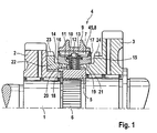
- FIG. 1 1 is a shaft of a manual transmission for motor vehicles, on which two gear wheels 2 and 3 are freely rotatably mounted. Between these two gear wheels 2 and 3, a synchronizer 4 is arranged, via which either one of the two gear wheels 2 or 3 can be coupled to the shaft 1. In this way, the gearbox is switched to different gear ratios.
- the synchronizing device 4 has a synchronizer body 5, which engages in rotation in a toothing 6 of the shaft. Furthermore, the synchronizer body 5 is provided on its outer circumference with an external toothing 7, in which teeth 8 of an internal toothing 45 of a sliding sleeve 9 engage. In the synchronizer body 5, a pressure piece 10 is further guided with a compression spring 11 which receives a spherical, in the longitudinal direction over the pressure piece 10 projecting locking element 12. The spherical detent element 12 protrudes from the synchronizer body 5 to approximately the tip circle of the external toothing 7.
- synchronizer rings 14 and 15 On both sides of the pressure piece 10 synchronizer rings 14 and 15 are arranged, the outside have a locking teeth 16 and 17 and inside a friction surface 18 and 19.
- the friction surfaces 18 and 19 of the synchronizer rings 14 and 15 cooperate with correspondingly formed friction surfaces 20 and 21 which are formed on the gear wheel 3 and a non-rotatably connected to the gear wheel coupling ring 22.
- an axial force is exerted on the respective synchronizer ring 14 or 15 during a corresponding locking synchronization via the pressure piece 10, during the initial synchronization, so that it exerts its friction surface 18 or 19 from the corresponding friction surface 20, 21 taken and rotated relative to the synchronizer body 5 by a certain angle.
- the locking teeth 16 blocks a further displacement of the sliding sleeve 9. This blocking effect is only canceled when a synchronization between the respective gear 2 and 3 and the shaft 1 is achieved.
- the internal toothing 8 of the sliding sleeve 9 is moved through the locking toothing 16 or 17 and finally reaches into engagement with a coupling toothing 23 or 24.
- the inner circumference of the sliding sleeve 9 has an internal toothing 45, the teeth 8, 8 ', viewed in cross section from the end face, taper in the direction of the transverse center plane of the sliding sleeve 9 so that centrally arranged on the transverse center plane recesses 34 to the Tooth flanks arise.
- These recesses 34 on the tooth flanks ensure that the teeth 8, 8 'of the sliding sleeve 9 and the coupling toothing of the coupling body or gear wheel, which are pushed into one another in a geared manner, do not separate from one another, in particular during load changes.
- the ends of the teeth 8, 8 'of sliding sleeves 9 are provided with roof slopes 32.
- the roof slopes 32 facilitate the engagement in the coupling teeth.
- the sliding sleeve 9 after FIG. 2 has a sleeve body 38 and two attached thereto rings 30, 31.
- the rings 30, 31 are integrally connected to the sleeve body 38 by welds 35 and form the shift fork guide 25. Together with the Wegzelnutground 36 lying between them outer periphery of the sliding sleeve 9 they limit the Heidelbergmülnut 26.
- the groove base 36 does not have the same distance d to the axis of rotation everywhere. Between the rings, at least one shoulder 29 or grooves 27, 28 are arranged.
- the grooves 27, 28 are circumferential and protrude below the rings 30, 31, so that a throat 39 is formed.
- both the mutually facing sides of the rings 30, 31 are processed without the machining tool in the region 40 of the Weggabelnutgrounds, which cooperates in the installed state with the shift fork, is applied. Also, the area 40, which cooperates with the shift fork in the installed state, can be processed without the tool comes into contact with the rings 30, 31.
- FIG. 3 shows a further not inventive sliding sleeve 9, in which the rooftops 33 of the teeth 8, 8 'with exemptions 37 are released.
- the sleeve body 38 is shown alone.
- the cohesive connection in the form of a weld 35 of the rings 30, 31 with the sleeve body 38 is not in the region of the exemptions 37, but adjacent to the grooves 27, 28.
- the outer ends 43, 44 of the grooves 27, 28 in this Embodiment lie in a plane with the inner walls 41, 42 of the rings 30, 31st
Description
Die Erfindung betrifft eine Schiebemuffe einer Synchronisiereinheit für Schaltgetriebe mit einem Muffenkörper, der an seinem Außenumfang eine Schaltgabelführung mit einer Schaltgabelnut aufnimmt und an seinem Innenumfang eine in Richtung der Längsmittelachse verlaufende Verzahnung aufweist.The invention relates to a sliding sleeve of a synchronizing unit for manual transmission with a sleeve body, which receives on its outer circumference a shift fork guide with a Schaltgabelnut and has on its inner circumference extending in the direction of the longitudinal central axis toothing.
Derartige Schiebemuffen sind in der Regel als Kupplungselemente in Synchronisiereinrichtungen von Hand geschalteter Kraftfahrzeuggetriebe eingesetzt. Sie verbinden eine Getriebewelle verdrehfest mit einem auf der Getriebewelle drehbar gelagerten Gangrad. Dabei ist die Schiebemuffe konzentrisch zur Getriebewelle angeordnet, verdrehfest und in Längsrichtung der Getriebewelle verschiebbar sowie mit einem Gangrad auf einem Synchronkörper kuppelbar.Such sliding sleeves are usually used as coupling elements in synchronizers manually switched motor vehicle transmission. They connect a gear shaft rotationally fixed with a rotatably mounted on the transmission shaft gear. In this case, the sliding sleeve is arranged concentrically to the transmission shaft, rotationally fixed and slidable in the longitudinal direction of the transmission shaft and coupled with a gear wheel on a synchronizer body.
Schiebemuffen gibt es in den verschiedensten Ausführungen. Zumeist weisen sie an ihrer Innenmantelfläche eine nach innen weisende Verzahnung auf, die in eine Gegenverzahnung des Synchronkörpers und im geschalteten Zustand in eine Verzahnung des Gangrads eingreift. Am Außenumfang der Schiebemuffe ist eine Schaltgabelführung vorgesehen. Mit der Schaltgabel wird die Schiebemuffe in Längsrichtung auf dem Synchronkörper verschoben, bis sie mit dem Zahnrad verbunden oder wieder zurück in ihrer Neutralstellung bewegt ist.Sliding sleeves are available in various designs. In most cases, they have on their inner lateral surface on an inwardly facing toothing, which engages in a counter-toothing of the synchronizer body and in the switched state in a toothing of the gear wheel. On the outer circumference of the sliding sleeve a shift fork guide is provided. With the shift fork, the sliding sleeve is moved in the longitudinal direction on the synchronizer body until it is connected to the gear or moved back to its neutral position.
In der Neutralstellung werden die Schiebemuffen oft axial durch ein Rastelement gehalten, das im Synchronkörper aufgenommen ist und zumeist federbelastet auf eine Ausnehmung wirkt. Die Ausnehmung ist - je nach Ausführung der Rastierung - an einzelnen oder allen nach innen gerichteten Zähnen der Schiebemuffe, den Riegelnutzähnen, ausgebildet. Das Rastelement bewirkt, dass die Schiebemuffe erst nach dem Überwinden eines definierten Widerstandes durch die Bedienperson, beim Schalten des Ganges, axial bewegt werden kann und sich nicht unbeabsichtigt und selbsttätig in axiale Richtung verschiebt. Um verschiedene Rastpunkte z. B. für eine Neutral- und eine Raststellung festzulegen oder Verschiebekräfte und Kraftverläufe unterschiedlicher Höhe zu definieren sind häufig zwei oder mehrere Ausnehmungen in Längsrichtung des Zahns hintereinander angeordnet. Neben oder unabhängig von den vorgenannten Rastelementen wirken bei anderen Synchronisiereinrichtungen Druckstücke oder Sperrelemente auf die Ausnehmungen des nach innen gerichteten Zahns. Die Druckstücke dienen als Betätigungselement für die Vorsynchronisierung. Bei axialem Verschieben der Schiebemuffe werden die Druckstücke durch diese mitgenommen. Dabei leiten sie den Prozess der Synchronisation ein, indem sie auf zwischen dem Gangrad und dem Synchronkörper angeordnete Synchronringe wirken.In the neutral position, the sliding sleeves are often held axially by a locking element which is received in the synchronizer body and usually spring-loaded acts on a recess. The recess is - depending on the design of the detent - on individual or all inwardly directed teeth of the sliding sleeve, the Riegelutzähnen formed. The locking element causes the sliding sleeve can only be moved axially after overcoming a defined resistance by the operator, when switching the gear, and does not move unintentionally and automatically in the axial direction. To different Rastpunkte z. B. set for a neutral and a detent position or to define displacement forces and force profiles of different heights are often two or more recesses in the longitudinal direction of the tooth arranged one behind the other. In addition to or independently of the aforementioned locking elements act in other synchronizers pressure pieces or locking elements on the recesses of the inwardly directed tooth. The plungers serve as an actuator for Vorsynchronisierung. In axial displacement of the sliding sleeve, the plungers are taken through them. They initiate the process of synchronization by acting on arranged between the gear and the synchronizer synchronizer rings.
Bei einem Gangwechsel wird die Schiebemuffe aus der Neutralstellung oder aus einer zweiten Endstellung in eine erste Endstellung verschoben, wobei die Schiebemuffe über das Druckstück in einem ersten Bewegungsschritt die Ansynchronisation, ein Angleichen der unterschiedlichen Drehzahlen zwischen dem Gangrad und dem Synchronkörper, einleitet. Weil die Schiebemuffe in diesem Prozess Kräfte aufnimmt, ist es erforderlich, dass sie sicher durch die Schaltgabel geführt wird. Diese Schaltgabelführungist beispielsweise dadurch realisiert, dass die Schiebemuffe an ihrem Außenumfang eine umlaufende Schaltgabelnut aufweist, in die eine halbkreisförmig ausgebildete Schaltgabel eingreift.In a gear change, the sliding sleeve is moved from the neutral position or from a second end position to a first end position, wherein the sliding sleeve via the pressure piece in a first movement step, the Ansynchronisation, an adjustment of the different speeds between the gear and the synchronizer body, initiates. Because the sliding sleeve absorbs forces in this process, it is required that it be guided safely through the shift fork. This shift fork guide is realized, for example, in that the sliding sleeve has on its outer circumference a circumferential Schaltgabelnut, in which engages a semicircular shift fork.
In der
In
Das Einbringen der Schaltgabelnut durch spanende Bearbeitung ist vergleichsweise aufwändig und kostenintensiv, da die Drehwerkzeuge schnell verschleißen. Insbesondere am Eckenradius tritt ein erhöhter Verschleiß auf. Bei spanlosen Herstellungsverfahren, insbesondere bei spanlos hergestellten Blechschiebemuffen mit freigestellten Dachspitzen der Zähne, besteht der Nachteil, dass separat vom Muffenkörper gefertigte Anschläge nicht von innen nach axial außen stoffschlüssig befestigt werden können.The introduction of Schaltgabelnut by machining is relatively complex and expensive, since the turning tools wear out quickly. In particular, at the corner radius occurs increased wear. In non-cutting production process, especially in non-cutting produced sheet metal sleeves with exempted rooftops of the teeth, there is the disadvantage that made separately from the sleeve body attacks can not be fastened from the inside to the outside cohesively.
Eine Schiebemuffe mit einer Blechverzahnung ist beispielsweise in
Des Weiteren ist bei Synchronisiereinheiten mit Leichtbauschaltgabeln, die beispielsweise aus Aluminium bestehen, und Schiebemuffen nach dem Stand der Technik der Verschleiß erhöht.Furthermore, in synchronizing units with lightweight folding forks, which consist for example of aluminum, and sliding sleeves according to the prior art, the wear is increased.
Der Erfindung liegt deshalb die Aufgabe zugrunde, eine Schiebemuffe zu schaffen, bei der die vorstehend genannten Nachteile beseitigt sind.The invention is therefore based on the object to provide a sliding sleeve, in which the aforementioned disadvantages are eliminated.
Erfindungsgemäß wird diese Aufgabe nach den Merkmalen des Anspruchs 1 dadurch gelöst, dass die Nuten zumindest teilweise radial zwischen den Ringen und dem Muffenkörper angeordnet sind.According to the invention this object is achieved according to the features of
Der Absatz oder die Nut werden im Falle der spanenden Herstellung in die Schaltgabelnut eingebracht, bevor die spanende Feinbearbeitung der Schaltgabelnut erfolgt. Sie ermöglichen es, dass die Schneidkante des Drehwerkzeugs beim Bearbeiten nicht gleichzeitig an Haupt- und Nebenschneidebene anliegt, sondern nur an einer Seite. Die Belastung des Drehwerkzeugs und damit sein Verschleiß sind wesentlich geringer.The shoulder or the groove are introduced in the case of machining production in the Schaltgabelnut before the fine machining of the Schaltgabelnut takes place. They make it possible that the cutting edge of the turning tool during machining is not applied simultaneously to the main and secondary cutting plane, but only on one side. The load of the rotary tool and thus its wear are much lower.
Sollte die Herstellung komplett spanlos erfolgen, ermöglicht es der Absatz bzw. die Nut in der Schaltgabelnut, eine Schaltgabelführung, die beispielsweise als ringförmige Scheibe auf dem Muffenkörper angeordnet ist, mit dem Muffenkörper schaltgabelnutseitig oder beidseitig stoffschlüssig zu verbinden. Dies ist insbesondere bei Schiebemuffen mit freigestellten Dachspitzen der Zähne von Bedeutung, weil eine stoffschlüssige Befestigung von separat hergestellten Schaltgabelführungen von axial außen nach innen z.B. durch Schweißen aufgrund Materialmangels nicht möglich ist. Die erfindungsgemäße Nut in der Schaltgabelnut ermöglicht ein Befestigen, das nun von axial innen nach außen erfolgen kann.If the production is carried out completely without cutting, it allows the paragraph or the groove in the Schaltgabelnut, a shift fork guide, which is arranged for example as an annular disc on the sleeve body to connect to the sleeve body switching fork groove side or both sides materially. This is particularly important in sliding sleeves with exposed roof tips of the teeth, because a cohesive attachment of separately manufactured shift fork guides from axially outside to inside, e.g. by welding due to lack of material is not possible. The groove according to the invention in the Schaltgabelnut allows a fastening, which can now be done from axially inside to outside.
Die Verwendung von Blech als Ausgangsmaterial zur Fertigung von Muffenkörpern oder Schiebemuffen erlaubt den Einsatz von einfachen Schnitt- und Formwerkzeugen. Profile wie die erwähnte Innenverzahnung, Ausnehmungen, Nuten, Aussparungen und Dachschrägen an der Verzahnung können in flach ausgerichtete Blechstreifen- oder Platinen durch z. B. Prägen, Rollieren und Walzen eingebracht werden. Im Gegensatz zu einem zylindrisch ausgeformten Muffenkörper nach dem Stand der Technik entstehen dabei keine Hinterschnitte in Entformungsrichtung der Werkzeuge.The use of sheet metal as a starting material for the manufacture of sleeve bodies or sliding sleeves allows the use of simple cutting and forming tools. Profiles such as the mentioned internal teeth, recesses, grooves, recesses and roof pitches on the teeth can be in flat-aligned Blechstreifen- or boards by z. B. embossing, rolling and rolling are introduced. In contrast to a cylindrically shaped sleeve body according to the prior art, no undercuts in Entformungsrichtung of the tools arise.
Die Ausgangsform des spanlos hergestellten Muffenkörpers liegt dabei in Form eines profilierten Blechstreifens vor. Die Profilierung enthält alle Elemente wie die Innenverzahnung und deren Nuten, Ausnehmungen, Aussparungen und Dachschrägen. Der Blechstreifen kann z. B. von einem endlosen Bandmaterial mit einer Länge, die dem Umfang des Muffenkörpers entspricht, getrennt werden. Die endgültige zylindrische Form des Muffenkörpers wird aus diesem Blechstreifen gebildet, der kreisförmig gebogen, an seinen Schnittkanten zusammengeführt und dort verschweißt ist. Die Schaltgabelführung kann sowohl vor dem Umformen eingebracht werden als auch nachher durch separat hergestellte Bauteile, die mit dem Muffenkörper verbunden werden, aufgebracht werden.The initial form of the non-machined sleeve body is in the form of a profiled sheet metal strip. The profiling includes all elements such as the internal teeth and their grooves, recesses, recesses and sloping roofs. The metal strip can, for. B. of an endless strip material having a length corresponding to the circumference of the sleeve body, are separated. The final cylindrical shape of the sleeve body is formed from this sheet metal strip, which is bent in a circle, brought together at its cutting edges and welded there. The shift fork guide can be introduced both before forming and subsequently be applied by separately manufactured components which are connected to the sleeve body.
Nach der Erfindung sind zwei Nuten in der Schaltgabelnut ausgebildet, wobei die Nuten an die Schaltgabelführung angrenzen oder teilweise zwischen Schaltgabelführung und Muffenkörper angeordnet sind. Die Schaltgabelführung am Außenumfang des Muffenkörpers ist durch zwei auf dessen Außenumfang angeordneten Ringe, die auch als Scheibe ausgebildet sein können, gebildet. Sowohl der Schaltgabelnutgrund als auch die seitlichen Wände der Schaltgabelführung bildenden Teile der Ringe können erfindungsgemäß jeweils einzeln bearbeitet werden, ohne dass ein Werkzeug an mehreren Seiten im Eingriff stehen muss.According to the invention, two grooves are formed in the Schaltgabelnut, the grooves adjacent to the shift fork guide or partially between the shift fork guide and sleeve body are arranged. The shift fork guide on the outer circumference of the sleeve body is formed by two arranged on the outer circumference rings, which may also be formed as a disc. Both the Schaltgabelnutgrund and the lateral walls of the shift fork guide forming parts of the rings according to the invention can each be individually processed without a tool must be engaged on several sides.
Die Nuten erfüllen eine weitere Funktion, um den Verschleiß einer mit der Schiebemuffe zusammen wirkenden Schaltgabel zu vermindern. Die Schaltgabel erstreckt sich im montierten Zustand der Synchronisiervorrichtung nicht bzw. nicht vollständig in die Nuten. Durch eine derartige Ausbildung ist es einerseits möglich, eine optimierte Auflagefläche, zwischen Schiebemuffe und Schaltgabel zu schaffen, andererseits kann sich Schmiermittel wie Öl in der Nut sammeln und eine Schmierung gewährleisten, wodurch der Verschleiß reduziert ist. Besonders vorteilhaft ist diese Wirkung bei Verwenden von Leichtbauschaltgabeln, die beispielsweise aus Stahlblech oder einem Leichtmetall bestehen.The grooves fulfill another function to reduce the wear of a shift fork cooperating with the sliding sleeve. The shift fork does not extend or not fully into the grooves in the assembled state of the synchronizer. By such a design, it is on the one hand possible to create an optimized bearing surface, between sliding sleeve and shift fork, on the other hand, can collect lubricant such as oil in the groove and ensure lubrication, whereby the wear is reduced. This effect is particularly advantageous when using lightweight folding forks, which consist for example of sheet steel or a light metal.
Eine erfindungsgemäße Schiebemuffe lässt sich besonders einfach herstellen, indem zunächst in einem ersten Schritt in entsprechend abgelängtes Bandmaterial die Nuten, der Absatz oder eine sonstige Außendurchmesseränderung eingebracht werden. Es ist dabei nicht von Bedeutung, ob das Einbringen der Verzahnung gleichzeitig, vorher oder nachher erfolgt. In einem nachfolgenden Schritt wird dann das Band zu einem ringförmigen Körper umgeformt, und die Bandenden werden aneinander dauerhaft fixiert. Optional kann dann eine Endbearbeitung erfolgen.A sliding sleeve according to the invention can be produced particularly easily, by first in a first step in appropriately cut strip material, the grooves, the paragraph or any other outer diameter change are introduced. It is not important whether the introduction of the teeth occurs simultaneously, before or after. In a subsequent step, the band is then formed into an annular body, and the band ends are permanently fixed to each other. Optionally, then a finishing can be done.
Die Erfindung wird nachstehend anhand eines Ausführungsbeispiels näher erläutert. Die dazugehörigen Zeichnungen zeigen:
Figur 1- einen Längsschnitt eines Teils einer Synchronisiervorrichtung nach dem Stand der Technik,
Figur 2- einen Längsschnitt einer erfindungsgemäßen Schiebemuffe,
- Figur 3
- eine vergrößerte Darstellung eines Längsschnittausschnitts einer weiteren nicht erfindungsgemäßen Schiebemuffe mit freigestellten Dachspitzen,
Figur 4- eine vergrößerte Darstellung des mit IV bezeichneten Ausschnitts aus
Figur 2 , Figur 5- eine perspektivisch Schrägansicht eines erfindungsgemäßen Muffenkörpers,
- Figur 6
- den Muffenkörper einer Schiebemuffe nach
Figur 3 in einer perspektivischen Schrägansicht.
- FIG. 1
- a longitudinal section of a part of a synchronizing device according to the prior art,
- FIG. 2
- a longitudinal section of a sliding sleeve according to the invention,
- FIG. 3
- an enlarged view of a longitudinal section detail of a further not according to the invention sliding sleeve with exposed rooftops,
- FIG. 4
- an enlarged view of the designated IV section
FIG. 2 . - FIG. 5
- a perspective oblique view of a sleeve body according to the invention,
- FIG. 6
- the sleeve body of a sliding sleeve after
FIG. 3 in a perspective oblique view.
In
Die Synchronisiereinrichtung 4 weist einen Synchronkörper 5 auf, der drehfest in eine Verzahnung 6 der Welle eingreift. Weiterhin ist der Synchronkörper 5 an seinem äußeren Umfang mit einer Außenverzahnung 7 versehen, in welche Zähne 8 einer Innenverzahnung 45 einer Schiebemuffe 9 eingreifen. Im Synchronkörper 5 ist weiterhin ein Druckstück 10 mit einer Druckfeder 11 geführt, das ein kugelförmiges, in Längsrichtung über das Druckstück 10 vorstehendes Rastelement 12 aufnimmt. Das kugelförmige Rastelement 12 ragt dabei aus dem Synchronkörper 5 bis etwa zum Kopfkreis der Außenverzahnung 7 vor. In einer Neutralstellung der Synchronisiereinrichtung 4, in keine der beiden möglichen Gangstufen geschaltet ist und sich somit die beiden Gangräder 2 und 3 frei gegenüber der Welle 1 drehen, greift das Rastelement 12 in eine in der Innenverzahnung 45 der Schiebemuffe 9 ausgebildete Riegelnut 13 ein.The synchronizing
Beiderseits des Druckstücks 10 sind Synchronringe 14 und 15 angeordnet, die außen eine Sperrverzahnung 16 und 17 und innen eine Reibfläche 18 und 19 aufweisen. Die Reibflächen 18 und 19 der Synchronringe 14 und 15 wirken zusammen mit entsprechend ausgebildeten Reibflächen 20 und 21, welche am Gangrad 3 sowie einem drehfest mit dem Gangrad verbundenen Kupplungsring 22 ausgebildet sind.On both sides of the
Während eines Schaltvorgangs wird bei einer entsprechenden Sperrsynchronisierung über das Druckstück 10 zunächst während des Ansynchronisierens eine axiale Kraft auf den jeweiligen Synchronring 14 oder 15 ausgeübt, so dass dieser über seine Reibfläche 18 oder 19 von der entsprechenden Reibfläche 20, 21 mitgenommen und gegenüber dem Synchronkörper 5 um einen bestimmten Winkel verdreht wird. In dieser Lage sperrt .die Sperrverzahnung 16 eine weitere Verschiebung der Schiebemuffe 9. Diese Sperrwirkung wird erst dann aufgehoben, wenn ein Gleichlauf zwischen dem jeweiligen Gangrad 2 bzw. 3 und der Welle 1 erzielt ist. In diesem Moment wird die Innenverzahnung 8 der Schiebemuffe 9 durch die Sperrverzahnung 16 bzw. 17 hindurch bewegt und gelangt schließlich in den Eingriff in eine Kupplungsverzahnung 23 bzw. 24.During a switching operation, an axial force is exerted on the
Aus
Die Schiebemuffe 9 nach
Bei einer spanenden Herstellung einer Schiebemuffe 9 nach
- 11
- Wellewave
- 22
- Gangradgear wheel
- 33
- Gangradgear wheel
- 44
- Synchronisiereinheitsynchronizing
- 55
- Muffenkörpersleeve body
- 66
- Verzahnunggearing
- 77
- Außenverzahnungexternal teeth
- 8, 8'8, 8 '
- Zähneteeth
- 99
- Schiebemuffesliding sleeve
- 1010
- DruckstückPressure piece
- 1111
- Druckfedercompression spring
- 1212
- Rastelementlocking element
- 1313
- Riegelnutlocking notch
- 1414
- Synchronringsynchronizer ring
- 1515
- Synchronringsynchronizer ring
- 1616
- Sperrverzahnunglocking teeth
- 1717
- Sperrverzahnunglocking teeth
- 1818
- Reibfläche von 14Friction surface of 14
- 1919
- Reibfläche von 15Friction surface of 15
- 2020
- Reibflächefriction surface
- 2121
- Reibflächefriction surface
- 2222
- Kupplungsringcoupling ring
- 2323
- Kupplungsverzahnungcoupling teeth
- 2424
- Kupplungsverzahnungcoupling teeth
- 2525
- SchaltgabelführungShift fork guide
- 2626
- SchaltgabelnutSchaltgabelnut
- 2727
- erste Nutfirst groove
- 2828
- zweite Nutsecond groove
- 2929
- Absatzparagraph
- 3030
- Ringring
- 3131
- Ringring
- 3232
- Dachschrägesloping roof
- 3333
- Dachspitzerooftop
- 3434
- Aussparungenrecesses
- 3535
- SchweißnahtWeld
- 3636
- SchaltgabelnutgrundSchaltgabelnutgrund
- 3737
- Freistellungexemption
- 3838
- Muffenkörpersleeve body
- 3939
- Kehlethroat
- 4040
- BereichArea
- 4141
- Innenwandinner wall
- 4242
- Innenwandinner wall
- 4343
- äußeres Endeouter end
- 4444
- äußeres Endeouter end
- 4545
- Innenverzahnunginternal gearing
- dd
- Außendurchmesserouter diameter
Claims (9)
- Sliding sleeve of a synchronizing unit (4) for manual transmissions, having a sleeve body (38) which on its outer circumference has a shift fork guide (25) with a shift fork groove (26) and on its inner circumference has an internal toothing (45) which runs in the direction of the longitudinal central axis, wherein the shift fork guide (25) is formed by two rings (30, 31) which are aligned parallel to one another and which are fixed to the outer circumference of the sleeve body (38) and which are produced separately from the sleeve body (38), wherein in the groove base (36) of the shift fork groove (26) there are arranged grooves (27, 28) which adjoin the rings (30, 31), characterized in that the grooves (27, 28) are arranged at least partially radially between the rings (30, 31) and the sleeve body (38).
- Sliding sleeve according to Claim 1, characterized in that the sleeve body (38) is composed, in its initial state, of a sheet-metal strip which is profiled at least on one side, which sheet-mental strip is curved into a circular shape and the cut edges of which are in the process brought together and welded to one another.
- Method for producing a sliding sleeve (9) according to Claim 1, characterized in that,- in a first method step, grooves (27, 28) and a rear-side toothing (45) are formed into a sheet-metal strip by stamping, roller-burnishing, rolling or profiling,- in that, in a second method step, the sheet-metal strip is shaped so as to form an annular sleeve body (38) such that the toothing forms an internal toothing (45) running in the direction of the longitudinal central axis,- in that, after the shaping, a separately produced shift fork guide (25) is attached to the outer circumference of the sleeve body (38) in such a way as to form a shift fork groove (26), in the groove base (36) of which the grooves (27, 28) are at least partially arranged.
- Method according to Claim 3, characterized in that the shift fork guide (25) is formed by shrink-fitting or welding of two rings (30, 31) arranged parallel to one another.
- Method according to Claim 4, characterized in that the rings (30, 31) are welded in the shift fork groove (26) from the inside outwards.
- Method according to Claim 5, characterized in that the internal toothing (45) has teeth (8, 8'), the tips (33) of which have clearances.
- Method according to Claim 3, characterized in that, after the second method step, the ends of the strip are permanently fixed to one another.
- Method according to Claim 4, characterized in that, after the attachment of the rings (30, 31), finish machining of the shift fork groove (26) is performed by means of a rotary tool which abuts only at the main cutting edge.
- Synchronizing unit having a sliding sleeve according to Claim 1 to 2 or having a sliding sleeve produced according to one of Claims 3-8.
Applications Claiming Priority (2)
| Application Number | Priority Date | Filing Date | Title |
|---|---|---|---|
| DE200510062171 DE102005062171A1 (en) | 2005-12-23 | 2005-12-23 | Sliding bushing for a synchronizing unit for a gearshift fork comprises a bushing body with an outer diameter which changes in the region of a gearshift fork groove |
| PCT/EP2006/068812 WO2007074000A1 (en) | 2005-12-23 | 2006-11-23 | Sliding sleeve |
Publications (2)
| Publication Number | Publication Date |
|---|---|
| EP1966503A1 EP1966503A1 (en) | 2008-09-10 |
| EP1966503B1 true EP1966503B1 (en) | 2012-09-26 |
Family
ID=37714550
Family Applications (1)
| Application Number | Title | Priority Date | Filing Date |
|---|---|---|---|
| EP06830093A Not-in-force EP1966503B1 (en) | 2005-12-23 | 2006-11-23 | Sliding sleeve |
Country Status (3)
| Country | Link |
|---|---|
| EP (1) | EP1966503B1 (en) |
| DE (1) | DE102005062171A1 (en) |
| WO (1) | WO2007074000A1 (en) |
Family Cites Families (12)
| Publication number | Priority date | Publication date | Assignee | Title |
|---|---|---|---|---|
| DE1822398U (en) * | 1960-09-13 | 1960-11-24 | Opel Adam Ag | CLUTCH GEAR IN GEAR CHANGE-OVER GEARS, ESPECIALLY OF MOTOR VEHICLES. |
| JPS5566009A (en) * | 1978-11-08 | 1980-05-19 | Nissan Motor Co Ltd | Coupling sleeve |
| DE3908989A1 (en) * | 1989-03-18 | 1990-09-20 | Sinterstahl Gmbh | METHOD FOR PRODUCING A SHIFTING OR SLIDING SLEEVE FOR A VEHICLE TRANSMISSION |
| FR2783027B1 (en) * | 1998-09-09 | 2000-10-13 | Renault | MANUAL GEARBOX SYNCHRONIZER |
| DE19851799A1 (en) * | 1998-11-09 | 2000-05-11 | Schaeffler Waelzlager Ohg | Slide sleeve for gear-box synchronizer unit has gear-shift fork guide, inner cogging, conical friction surfaces, friction rings and main body |
| DE10127140A1 (en) * | 2000-07-12 | 2002-02-07 | Schaeffler Waelzlager Ohg | Coupling element of a clutch unit for manual transmissions |
| ITMI20011450A1 (en) * | 2000-07-12 | 2003-01-06 | Schaeffler Waelzlager Ohg | COUPLING ELEMENT OF A COUPLING UNIT FOR SPEED CHANGE |
| DE10053031A1 (en) * | 2000-10-26 | 2002-05-08 | Ina Schaeffler Kg | Toothing has teeth interconnected by means of protrusion formed on flank side of one tooth engaging in corresponding recess provided in adjacent tooth |
| DE10122184A1 (en) * | 2001-05-08 | 2002-11-14 | Ina Schaeffler Kg | To shape tooth structures, in a row of teeth, the shaping is by plastic distortion of the tooth material, and the displaced material is taken up by a prepared opening |
| DE10149845B4 (en) * | 2001-10-10 | 2009-01-15 | Schaeffler Kg | Basic body of a sliding sleeve |
| DE10229911A1 (en) * | 2002-07-04 | 2004-01-15 | Ina-Schaeffler Kg | Sliding sleeve of a clutch |
| JP2005201415A (en) * | 2004-01-19 | 2005-07-28 | Nissan Diesel Motor Co Ltd | Synchronizer detent structure for transmission |
-
2005
- 2005-12-23 DE DE200510062171 patent/DE102005062171A1/en not_active Withdrawn
-
2006
- 2006-11-23 WO PCT/EP2006/068812 patent/WO2007074000A1/en active Application Filing
- 2006-11-23 EP EP06830093A patent/EP1966503B1/en not_active Not-in-force
Also Published As
| Publication number | Publication date |
|---|---|
| WO2007074000A1 (en) | 2007-07-05 |
| DE102005062171A1 (en) | 2007-06-28 |
| EP1966503A1 (en) | 2008-09-10 |
Similar Documents
| Publication | Publication Date | Title |
|---|---|---|
| EP0955481B1 (en) | Shift sleeve of a synchronizer assembly for a gearbox | |
| EP2478243B1 (en) | Transmission ring for a synchronisation assembly for a gear box | |
| EP1649196B1 (en) | Planet carrier for a gearbox | |
| EP1828647B1 (en) | Shift device | |
| EP2092206B1 (en) | Sliding sleeve of a synchronizing device | |
| EP1650457B1 (en) | Gear-shifting device | |
| DE102006060535A1 (en) | Synchronization device e.g. for gearbox, has sliding collar having radial acting spring element and which contacts counter area on synchronous ring and on opposite surface deep recess is formed | |
| DE2510657A1 (en) | Synchronizing ring for gear wheel coupling - has friction taper on secondary rings to produce drive and axial gear teeth | |
| DE102005053989B4 (en) | Process for producing a coupling body | |
| EP1192364B1 (en) | Slip joint of a synchronization unit for transmissions | |
| WO2008028784A1 (en) | Synchronizing body | |
| DE102008049978A1 (en) | Shifting unit for manual gearbox of motor vehicle, has tooth intermediate spaces rotationally coupled or decoupled with teeth of internal gear of sliding sleeve, and stops arranged on clutch bodies to limit axial displaceability of sleeve | |
| DE102006061415A1 (en) | Synchronizer ring of a synchronizer | |
| EP1966503B1 (en) | Sliding sleeve | |
| DE102013221246A1 (en) | synchronizer | |
| WO2007074031A1 (en) | Synchronizing device | |
| DE102005061481A1 (en) | Switching device e.g. for switching gears in manual transmission, has sliding sleeve adjustable from neutral position toward wheel and has teeth interfering with teeth | |
| DE102016204156B3 (en) | Sliding sleeve for shifting gear stages of a manual transmission | |
| DE3930173C1 (en) | ||
| DE102018008500A1 (en) | Transmission synchronization device | |
| DE102007059843A1 (en) | Sliding sleeve for use in gear shifting-change-speed gear of motor vehicle, has teeth ring with outer mantle surface comprising circulating groove in area of transition between disk and teeth ring | |
| EP1146243B1 (en) | Synchronizer assembly for shift clutch | |
| DE102015111802B4 (en) | Switching cylinder for a switching arrangement of a motor vehicle transmission | |
| DE102011075503A1 (en) | Synchronizing device for motor car speed change gearbox, has locking device comprising locking element, and passage provided with guiding groove whose end is axially limited by stoppers, and wing that is movable in groove in axial direction | |
| EP1365166B1 (en) | Torque transmission device |
Legal Events
| Date | Code | Title | Description |
|---|---|---|---|
| PUAI | Public reference made under article 153(3) epc to a published international application that has entered the european phase |
Free format text: ORIGINAL CODE: 0009012 |
|
| 17P | Request for examination filed |
Effective date: 20080723 |
|
| AK | Designated contracting states |
Kind code of ref document: A1 Designated state(s): AT BE BG CH CY CZ DE DK EE ES FI FR GB GR HU IE IS IT LI LT LU LV MC NL PL PT RO SE SI SK TR |
|
| 17Q | First examination report despatched |
Effective date: 20081120 |
|
| RAP1 | Party data changed (applicant data changed or rights of an application transferred) |
Owner name: SCHAEFFLER TECHNOLOGIES AG & CO. KG |
|
| GRAP | Despatch of communication of intention to grant a patent |
Free format text: ORIGINAL CODE: EPIDOSNIGR1 |
|
| DAX | Request for extension of the european patent (deleted) | ||
| GRAS | Grant fee paid |
Free format text: ORIGINAL CODE: EPIDOSNIGR3 |
|
| GRAA | (expected) grant |
Free format text: ORIGINAL CODE: 0009210 |
|
| AK | Designated contracting states |
Kind code of ref document: B1 Designated state(s): AT BE BG CH CY CZ DE DK EE ES FI FR GB GR HU IE IS IT LI LT LU LV MC NL PL PT RO SE SI SK TR |
|
| REG | Reference to a national code |
Ref country code: GB Ref legal event code: FG4D Free format text: NOT ENGLISH |
|
| REG | Reference to a national code |
Ref country code: CH Ref legal event code: EP |
|
| REG | Reference to a national code |
Ref country code: AT Ref legal event code: REF Ref document number: 577204 Country of ref document: AT Kind code of ref document: T Effective date: 20121015 |
|
| REG | Reference to a national code |
Ref country code: IE Ref legal event code: FG4D Free format text: LANGUAGE OF EP DOCUMENT: GERMAN |
|
| REG | Reference to a national code |
Ref country code: DE Ref legal event code: R096 Ref document number: 502006012024 Country of ref document: DE Effective date: 20121115 |
|
| PG25 | Lapsed in a contracting state [announced via postgrant information from national office to epo] |
Ref country code: FI Free format text: LAPSE BECAUSE OF FAILURE TO SUBMIT A TRANSLATION OF THE DESCRIPTION OR TO PAY THE FEE WITHIN THE PRESCRIBED TIME-LIMIT Effective date: 20120926 Ref country code: LT Free format text: LAPSE BECAUSE OF FAILURE TO SUBMIT A TRANSLATION OF THE DESCRIPTION OR TO PAY THE FEE WITHIN THE PRESCRIBED TIME-LIMIT Effective date: 20120926 |
|
| REG | Reference to a national code |
Ref country code: LT Ref legal event code: MG4D Effective date: 20120919 |
|
| REG | Reference to a national code |
Ref country code: NL Ref legal event code: VDEP Effective date: 20120926 |
|
| PG25 | Lapsed in a contracting state [announced via postgrant information from national office to epo] |
Ref country code: SI Free format text: LAPSE BECAUSE OF FAILURE TO SUBMIT A TRANSLATION OF THE DESCRIPTION OR TO PAY THE FEE WITHIN THE PRESCRIBED TIME-LIMIT Effective date: 20120926 Ref country code: SE Free format text: LAPSE BECAUSE OF FAILURE TO SUBMIT A TRANSLATION OF THE DESCRIPTION OR TO PAY THE FEE WITHIN THE PRESCRIBED TIME-LIMIT Effective date: 20120926 Ref country code: GR Free format text: LAPSE BECAUSE OF FAILURE TO SUBMIT A TRANSLATION OF THE DESCRIPTION OR TO PAY THE FEE WITHIN THE PRESCRIBED TIME-LIMIT Effective date: 20121227 Ref country code: LV Free format text: LAPSE BECAUSE OF FAILURE TO SUBMIT A TRANSLATION OF THE DESCRIPTION OR TO PAY THE FEE WITHIN THE PRESCRIBED TIME-LIMIT Effective date: 20120926 |
|
| PG25 | Lapsed in a contracting state [announced via postgrant information from national office to epo] |
Ref country code: CZ Free format text: LAPSE BECAUSE OF FAILURE TO SUBMIT A TRANSLATION OF THE DESCRIPTION OR TO PAY THE FEE WITHIN THE PRESCRIBED TIME-LIMIT Effective date: 20120926 Ref country code: RO Free format text: LAPSE BECAUSE OF FAILURE TO SUBMIT A TRANSLATION OF THE DESCRIPTION OR TO PAY THE FEE WITHIN THE PRESCRIBED TIME-LIMIT Effective date: 20120926 Ref country code: NL Free format text: LAPSE BECAUSE OF FAILURE TO SUBMIT A TRANSLATION OF THE DESCRIPTION OR TO PAY THE FEE WITHIN THE PRESCRIBED TIME-LIMIT Effective date: 20120926 Ref country code: EE Free format text: LAPSE BECAUSE OF FAILURE TO SUBMIT A TRANSLATION OF THE DESCRIPTION OR TO PAY THE FEE WITHIN THE PRESCRIBED TIME-LIMIT Effective date: 20120926 Ref country code: IS Free format text: LAPSE BECAUSE OF FAILURE TO SUBMIT A TRANSLATION OF THE DESCRIPTION OR TO PAY THE FEE WITHIN THE PRESCRIBED TIME-LIMIT Effective date: 20130126 Ref country code: ES Free format text: LAPSE BECAUSE OF FAILURE TO SUBMIT A TRANSLATION OF THE DESCRIPTION OR TO PAY THE FEE WITHIN THE PRESCRIBED TIME-LIMIT Effective date: 20130106 |
|
| BERE | Be: lapsed |
Owner name: SCHAEFFLER TECHNOLOGIES A.G. & CO. KG Effective date: 20121130 |
|
| PG25 | Lapsed in a contracting state [announced via postgrant information from national office to epo] |
Ref country code: PL Free format text: LAPSE BECAUSE OF FAILURE TO SUBMIT A TRANSLATION OF THE DESCRIPTION OR TO PAY THE FEE WITHIN THE PRESCRIBED TIME-LIMIT Effective date: 20120926 Ref country code: CY Free format text: LAPSE BECAUSE OF FAILURE TO SUBMIT A TRANSLATION OF THE DESCRIPTION OR TO PAY THE FEE WITHIN THE PRESCRIBED TIME-LIMIT Effective date: 20120926 Ref country code: PT Free format text: LAPSE BECAUSE OF FAILURE TO SUBMIT A TRANSLATION OF THE DESCRIPTION OR TO PAY THE FEE WITHIN THE PRESCRIBED TIME-LIMIT Effective date: 20130128 Ref country code: SK Free format text: LAPSE BECAUSE OF FAILURE TO SUBMIT A TRANSLATION OF THE DESCRIPTION OR TO PAY THE FEE WITHIN THE PRESCRIBED TIME-LIMIT Effective date: 20120926 |
|
| REG | Reference to a national code |
Ref country code: CH Ref legal event code: PL |
|
| PG25 | Lapsed in a contracting state [announced via postgrant information from national office to epo] |
Ref country code: LI Free format text: LAPSE BECAUSE OF NON-PAYMENT OF DUE FEES Effective date: 20121130 Ref country code: BG Free format text: LAPSE BECAUSE OF FAILURE TO SUBMIT A TRANSLATION OF THE DESCRIPTION OR TO PAY THE FEE WITHIN THE PRESCRIBED TIME-LIMIT Effective date: 20121226 Ref country code: DK Free format text: LAPSE BECAUSE OF FAILURE TO SUBMIT A TRANSLATION OF THE DESCRIPTION OR TO PAY THE FEE WITHIN THE PRESCRIBED TIME-LIMIT Effective date: 20120926 Ref country code: CH Free format text: LAPSE BECAUSE OF NON-PAYMENT OF DUE FEES Effective date: 20121130 |
|
| PLBE | No opposition filed within time limit |
Free format text: ORIGINAL CODE: 0009261 |
|
| STAA | Information on the status of an ep patent application or granted ep patent |
Free format text: STATUS: NO OPPOSITION FILED WITHIN TIME LIMIT |
|
| REG | Reference to a national code |
Ref country code: IE Ref legal event code: MM4A |
|
| REG | Reference to a national code |
Ref country code: FR Ref legal event code: ST Effective date: 20130731 |
|
| GBPC | Gb: european patent ceased through non-payment of renewal fee |
Effective date: 20121226 |
|
| PG25 | Lapsed in a contracting state [announced via postgrant information from national office to epo] |
Ref country code: IT Free format text: LAPSE BECAUSE OF FAILURE TO SUBMIT A TRANSLATION OF THE DESCRIPTION OR TO PAY THE FEE WITHIN THE PRESCRIBED TIME-LIMIT Effective date: 20120926 Ref country code: BE Free format text: LAPSE BECAUSE OF NON-PAYMENT OF DUE FEES Effective date: 20121130 |
|
| 26N | No opposition filed |
Effective date: 20130627 |
|
| REG | Reference to a national code |
Ref country code: DE Ref legal event code: R097 Ref document number: 502006012024 Country of ref document: DE Effective date: 20130627 |
|
| PG25 | Lapsed in a contracting state [announced via postgrant information from national office to epo] |
Ref country code: IE Free format text: LAPSE BECAUSE OF NON-PAYMENT OF DUE FEES Effective date: 20121123 |
|
| PG25 | Lapsed in a contracting state [announced via postgrant information from national office to epo] |
Ref country code: GB Free format text: LAPSE BECAUSE OF NON-PAYMENT OF DUE FEES Effective date: 20121226 Ref country code: FR Free format text: LAPSE BECAUSE OF NON-PAYMENT OF DUE FEES Effective date: 20121130 |
|
| REG | Reference to a national code |
Ref country code: AT Ref legal event code: MM01 Ref document number: 577204 Country of ref document: AT Kind code of ref document: T Effective date: 20121130 |
|
| PG25 | Lapsed in a contracting state [announced via postgrant information from national office to epo] |
Ref country code: AT Free format text: LAPSE BECAUSE OF NON-PAYMENT OF DUE FEES Effective date: 20121130 |
|
| REG | Reference to a national code |
Ref country code: DE Ref legal event code: R081 Ref document number: 502006012024 Country of ref document: DE Owner name: SCHAEFFLER TECHNOLOGIES GMBH & CO. KG, DE Free format text: FORMER OWNER: SCHAEFFLER TECHNOLOGIES AG & CO. KG, 91074 HERZOGENAURACH, DE Effective date: 20140212 Ref country code: DE Ref legal event code: R081 Ref document number: 502006012024 Country of ref document: DE Owner name: SCHAEFFLER TECHNOLOGIES AG & CO. KG, DE Free format text: FORMER OWNER: SCHAEFFLER TECHNOLOGIES AG & CO. KG, 91074 HERZOGENAURACH, DE Effective date: 20140212 |
|
| PG25 | Lapsed in a contracting state [announced via postgrant information from national office to epo] |
Ref country code: MC Free format text: LAPSE BECAUSE OF NON-PAYMENT OF DUE FEES Effective date: 20121130 Ref country code: TR Free format text: LAPSE BECAUSE OF FAILURE TO SUBMIT A TRANSLATION OF THE DESCRIPTION OR TO PAY THE FEE WITHIN THE PRESCRIBED TIME-LIMIT Effective date: 20120926 |
|
| PG25 | Lapsed in a contracting state [announced via postgrant information from national office to epo] |
Ref country code: LU Free format text: LAPSE BECAUSE OF NON-PAYMENT OF DUE FEES Effective date: 20121123 |
|
| PG25 | Lapsed in a contracting state [announced via postgrant information from national office to epo] |
Ref country code: HU Free format text: LAPSE BECAUSE OF FAILURE TO SUBMIT A TRANSLATION OF THE DESCRIPTION OR TO PAY THE FEE WITHIN THE PRESCRIBED TIME-LIMIT Effective date: 20061123 |
|
| REG | Reference to a national code |
Ref country code: DE Ref legal event code: R081 Ref document number: 502006012024 Country of ref document: DE Owner name: SCHAEFFLER TECHNOLOGIES AG & CO. KG, DE Free format text: FORMER OWNER: SCHAEFFLER TECHNOLOGIES GMBH & CO. KG, 91074 HERZOGENAURACH, DE Effective date: 20150123 |
|
| PGFP | Annual fee paid to national office [announced via postgrant information from national office to epo] |
Ref country code: DE Payment date: 20200130 Year of fee payment: 14 |
|
| REG | Reference to a national code |
Ref country code: DE Ref legal event code: R119 Ref document number: 502006012024 Country of ref document: DE |
|
| PG25 | Lapsed in a contracting state [announced via postgrant information from national office to epo] |
Ref country code: DE Free format text: LAPSE BECAUSE OF NON-PAYMENT OF DUE FEES Effective date: 20210601 |
|
| P01 | Opt-out of the competence of the unified patent court (upc) registered |
Effective date: 20230522 |