EP1966466B1 - Apparatus for separating oil from blow-by gas of engine - Google Patents
Apparatus for separating oil from blow-by gas of engine Download PDFInfo
- Publication number
- EP1966466B1 EP1966466B1 EP06835395A EP06835395A EP1966466B1 EP 1966466 B1 EP1966466 B1 EP 1966466B1 EP 06835395 A EP06835395 A EP 06835395A EP 06835395 A EP06835395 A EP 06835395A EP 1966466 B1 EP1966466 B1 EP 1966466B1
- Authority
- EP
- European Patent Office
- Prior art keywords
- blow
- gas
- engine
- cover
- oil
- Prior art date
- Legal status (The legal status is an assumption and is not a legal conclusion. Google has not performed a legal analysis and makes no representation as to the accuracy of the status listed.)
- Not-in-force
Links
- 238000005192 partition Methods 0.000 claims abstract description 45
- 238000010276 construction Methods 0.000 abstract description 3
- 230000002708 enhancing effect Effects 0.000 abstract 1
- 239000007789 gas Substances 0.000 description 145
- 238000000034 method Methods 0.000 description 5
- 238000004519 manufacturing process Methods 0.000 description 3
- 238000000926 separation method Methods 0.000 description 3
- 230000001133 acceleration Effects 0.000 description 2
- 239000000567 combustion gas Substances 0.000 description 1
- 230000000694 effects Effects 0.000 description 1
- 239000013013 elastic material Substances 0.000 description 1
- 238000004880 explosion Methods 0.000 description 1
- 239000012530 fluid Substances 0.000 description 1
- 238000009434 installation Methods 0.000 description 1
Images




Classifications
-
- F—MECHANICAL ENGINEERING; LIGHTING; HEATING; WEAPONS; BLASTING
- F01—MACHINES OR ENGINES IN GENERAL; ENGINE PLANTS IN GENERAL; STEAM ENGINES
- F01M—LUBRICATING OF MACHINES OR ENGINES IN GENERAL; LUBRICATING INTERNAL COMBUSTION ENGINES; CRANKCASE VENTILATING
- F01M13/00—Crankcase ventilating or breathing
- F01M13/04—Crankcase ventilating or breathing having means for purifying air before leaving crankcase, e.g. removing oil
- F01M13/0416—Crankcase ventilating or breathing having means for purifying air before leaving crankcase, e.g. removing oil arranged in valve-covers
-
- F—MECHANICAL ENGINEERING; LIGHTING; HEATING; WEAPONS; BLASTING
- F01—MACHINES OR ENGINES IN GENERAL; ENGINE PLANTS IN GENERAL; STEAM ENGINES
- F01M—LUBRICATING OF MACHINES OR ENGINES IN GENERAL; LUBRICATING INTERNAL COMBUSTION ENGINES; CRANKCASE VENTILATING
- F01M13/00—Crankcase ventilating or breathing
- F01M13/0011—Breather valves
-
- F—MECHANICAL ENGINEERING; LIGHTING; HEATING; WEAPONS; BLASTING
- F16—ENGINEERING ELEMENTS AND UNITS; GENERAL MEASURES FOR PRODUCING AND MAINTAINING EFFECTIVE FUNCTIONING OF MACHINES OR INSTALLATIONS; THERMAL INSULATION IN GENERAL
- F16K—VALVES; TAPS; COCKS; ACTUATING-FLOATS; DEVICES FOR VENTING OR AERATING
- F16K15/00—Check valves
- F16K15/02—Check valves with guided rigid valve members
- F16K15/021—Check valves with guided rigid valve members the valve member being a movable body around which the medium flows when the valve is open
- F16K15/023—Check valves with guided rigid valve members the valve member being a movable body around which the medium flows when the valve is open the valve member consisting only of a predominantly disc-shaped flat element
-
- F—MECHANICAL ENGINEERING; LIGHTING; HEATING; WEAPONS; BLASTING
- F16—ENGINEERING ELEMENTS AND UNITS; GENERAL MEASURES FOR PRODUCING AND MAINTAINING EFFECTIVE FUNCTIONING OF MACHINES OR INSTALLATIONS; THERMAL INSULATION IN GENERAL
- F16K—VALVES; TAPS; COCKS; ACTUATING-FLOATS; DEVICES FOR VENTING OR AERATING
- F16K15/00—Check valves
- F16K15/14—Check valves with flexible valve members
- F16K15/144—Check valves with flexible valve members the closure elements being fixed along all or a part of their periphery
-
- F—MECHANICAL ENGINEERING; LIGHTING; HEATING; WEAPONS; BLASTING
- F16—ENGINEERING ELEMENTS AND UNITS; GENERAL MEASURES FOR PRODUCING AND MAINTAINING EFFECTIVE FUNCTIONING OF MACHINES OR INSTALLATIONS; THERMAL INSULATION IN GENERAL
- F16K—VALVES; TAPS; COCKS; ACTUATING-FLOATS; DEVICES FOR VENTING OR AERATING
- F16K17/00—Safety valves; Equalising valves, e.g. pressure relief valves
- F16K17/02—Safety valves; Equalising valves, e.g. pressure relief valves opening on surplus pressure on one side; closing on insufficient pressure on one side
- F16K17/04—Safety valves; Equalising valves, e.g. pressure relief valves opening on surplus pressure on one side; closing on insufficient pressure on one side spring-loaded
- F16K17/0493—Safety valves; Equalising valves, e.g. pressure relief valves opening on surplus pressure on one side; closing on insufficient pressure on one side spring-loaded with a spring other than a helicoidal spring
-
- F—MECHANICAL ENGINEERING; LIGHTING; HEATING; WEAPONS; BLASTING
- F01—MACHINES OR ENGINES IN GENERAL; ENGINE PLANTS IN GENERAL; STEAM ENGINES
- F01M—LUBRICATING OF MACHINES OR ENGINES IN GENERAL; LUBRICATING INTERNAL COMBUSTION ENGINES; CRANKCASE VENTILATING
- F01M13/00—Crankcase ventilating or breathing
- F01M2013/0005—Crankcase ventilating or breathing with systems regulating the pressure in the carter
-
- F—MECHANICAL ENGINEERING; LIGHTING; HEATING; WEAPONS; BLASTING
- F01—MACHINES OR ENGINES IN GENERAL; ENGINE PLANTS IN GENERAL; STEAM ENGINES
- F01M—LUBRICATING OF MACHINES OR ENGINES IN GENERAL; LUBRICATING INTERNAL COMBUSTION ENGINES; CRANKCASE VENTILATING
- F01M13/00—Crankcase ventilating or breathing
- F01M2013/0038—Layout of crankcase breathing systems
- F01M2013/005—Layout of crankcase breathing systems having one or more deoilers
-
- F—MECHANICAL ENGINEERING; LIGHTING; HEATING; WEAPONS; BLASTING
- F01—MACHINES OR ENGINES IN GENERAL; ENGINE PLANTS IN GENERAL; STEAM ENGINES
- F01M—LUBRICATING OF MACHINES OR ENGINES IN GENERAL; LUBRICATING INTERNAL COMBUSTION ENGINES; CRANKCASE VENTILATING
- F01M13/00—Crankcase ventilating or breathing
- F01M2013/0038—Layout of crankcase breathing systems
- F01M2013/005—Layout of crankcase breathing systems having one or more deoilers
- F01M2013/0055—Layout of crankcase breathing systems having one or more deoilers with a by-pass
-
- F—MECHANICAL ENGINEERING; LIGHTING; HEATING; WEAPONS; BLASTING
- F01—MACHINES OR ENGINES IN GENERAL; ENGINE PLANTS IN GENERAL; STEAM ENGINES
- F01M—LUBRICATING OF MACHINES OR ENGINES IN GENERAL; LUBRICATING INTERNAL COMBUSTION ENGINES; CRANKCASE VENTILATING
- F01M13/00—Crankcase ventilating or breathing
- F01M13/04—Crankcase ventilating or breathing having means for purifying air before leaving crankcase, e.g. removing oil
- F01M2013/0422—Separating oil and gas with a centrifuge device
-
- F—MECHANICAL ENGINEERING; LIGHTING; HEATING; WEAPONS; BLASTING
- F01—MACHINES OR ENGINES IN GENERAL; ENGINE PLANTS IN GENERAL; STEAM ENGINES
- F01M—LUBRICATING OF MACHINES OR ENGINES IN GENERAL; LUBRICATING INTERNAL COMBUSTION ENGINES; CRANKCASE VENTILATING
- F01M13/00—Crankcase ventilating or breathing
- F01M13/04—Crankcase ventilating or breathing having means for purifying air before leaving crankcase, e.g. removing oil
- F01M2013/0422—Separating oil and gas with a centrifuge device
- F01M2013/0427—Separating oil and gas with a centrifuge device the centrifuge device having no rotating part, e.g. cyclone
-
- F—MECHANICAL ENGINEERING; LIGHTING; HEATING; WEAPONS; BLASTING
- F01—MACHINES OR ENGINES IN GENERAL; ENGINE PLANTS IN GENERAL; STEAM ENGINES
- F01M—LUBRICATING OF MACHINES OR ENGINES IN GENERAL; LUBRICATING INTERNAL COMBUSTION ENGINES; CRANKCASE VENTILATING
- F01M13/00—Crankcase ventilating or breathing
- F01M13/04—Crankcase ventilating or breathing having means for purifying air before leaving crankcase, e.g. removing oil
- F01M2013/0461—Crankcase ventilating or breathing having means for purifying air before leaving crankcase, e.g. removing oil with a labyrinth
Definitions
- blow-by gas which is drawn into the crankcase, is guided to a cylinder head cover, which is disposed on top of the cylinder head of the engine.
- the blow-by gas which is guided to the cylinder head cover, is then guided to an intake system of the engine and is thus reburned.
- DE 20 2004 009 673 U1 refers to a valve assembly for deaerating of a crankcase showing same constructional features as defined in the preamble of claim 1.
- an inlet 2 and an outlet 3 for blow-by gas are formed in a baffle compartment 1. Furthermore, several partition walls 4 are alternately disposed in the baffle compartment 1 such that the path along which blow-by gas passes has a zigzag structure. Thus, oil contained in blow-by gas falls due to its own weight or sticks to the partition walls 4. Thereafter, the separated oil is discharged through a separate oil discharge passage (not shown).
- the conventional fixed-type oil separating apparatus having the stationary partition walls is problematic in that the efficiency with which oil is separated from blow-by gas varies depending on the speed at which blow-by gas passes through the baffle compartment 1, that is, depending on the conditions in the engine.
- an apparatus for separating oil from blow-by gas which includes movable impactors, which are rotatably provided around an inlet and an outlet of a baffle compartment, an actuator for rotating the movable impactors, and a controller that operates the actuator depending on the operation conditions of the engine, was proposed in Korean Patent Laid-open Publication No. 2005-0045330 .
- the variable oil separating apparatus has problems in that, because several separate electric components, such as the actuator, the controller and a sensor for detecting the operation conditions of the engine, are required, the manufacturing costs are increased, and, when taking high-temperature and high-pressure conditions of the engine into account, the reliability and durability of the actuator and controller are markedly reduced.
- the movable impactor has a hinged door structure, that is, it is too simple. Therefore, because the contact area between the movable impactor and blow-by gas, which passes through the movable impactor, is relatively small, the oil separating function is not reliably conducted. As well, the shape of the contact surface is fixed rather than changing depending on the pressure of blow-by gas. As a result, there is a problem in that, when the engine is operating at high speed, the oil separating ability is reduced.
- an object of the present invention is to provide a variable apparatus for separating oil from blow-by gas in an engine in which, when the engine is operating at low speed, relatively low negative pressure is applied to blow-by gas, and, when the engine is operating at high speed, the amount of negative pressure applied to blow-by gas is increased in order to actively respond to the speed at which blow-by gas flows, thus having markedly enhanced ability to separate oil from blow-by gas even when operating at high speed.
- Another object of the present invention is to provide a variable apparatus for separating oil from blow-by gas in an engine in which, in the case where the ability to separate oil from the blow-by gas is reduced when the flow speed of blow-by gas is low, blow-by gas is accelerated and rotated to enhance the oil separating ability and the pressure in a crankcase is prevented from becoming positive pressure by reducing a difference in pressure, and in which, when the engine is operating at high speed, the area of the partition wall that contacts blow-by gas is increased to enhance the oil separating ability and the difference in pressure is increased such that the pressure in the crankcase can fall within a desired range.
- the present invention provides a variable apparatus for separating oil from blow-by gas in an engine which appropriately responds to the speed at which blow-by gas flows, so that the efficiency of separation of oil from blow-by gas can be increased even when the blow-by gas flows at a high speed. Furthermore, in the present invention, because an elastic member having a spiral shape has a simple structure and the number of parts is reduced, the reliability of the assembled apparatus is enhanced, the cost of manufacturing the apparatus is reduced, and the durability thereof is markedly enhanced. In addition, in response to the pressure of blow-by gas, the elastic member extends or contracts and thus guides the rotary flow of blow-by gas and, simultaneously, the shape of the contact surface with the blow-by gas is changed, so that the ability to separate oil from blow-by gas can be increased.
- FIG. 4 is a sectional view showing the part of the variable apparatus of FIG. 2 which is operating at high speed;
- FIG. 7 is a view corresponding to FIG. 6 , but showing another example of a baffle compartment in which variable apparatuses for separating oil from blow-by gas are installed;
- variable apparatuses for separating oil from blow-by gas in engines according to a preferred embodiment of the present invention will be described in detail with reference to the attached drawings.
- a variable apparatus for separating oil from blow-by gas in an engine is installed in a baffle compartment of a cylinder head cover of the engine, and includes a partition wall 10, a cover 20 and a plurality of elastic members 30.
- the partition wall 10 has a blow-by gas passing hole 10a therein.
- the single partition wall 10 may be provided in the baffle compartment 11.
- several partition walls 10 may be provided in the baffle compartment 11.
- the pressure of blow-by gas, which is applied to the cover 20 pertains to the area of the cover 20.
- the area of the cover 20 can be optimized through testing.
- the elastic members 30 are interposed between the partition wall 10 and the cover 20 and are made of elastic material which can be changed in shape such that the cover 20 is moved away from the partition wall 10 by a predetermined distance depending on the pressure of blow-by gas supplied from the engine, and passages are thus defined.
- each elastic member 30 is a spiral elastic plate, which has a surface twisted into a spiral having a predetermined angle, so that, when the elastic member 30 is elastically extended, blow-by gas is spirally moved under the guidance of the elastic member 30.
- the angle at which the elastic member 30 is twisted and the number of twists of the elastic member 30 may be variously changed. Furthermore, several elastic members 30 may be installed parallel to each other around the passing hole 10a.
- the elasticity of the elastic member 30 can be also optimally designed through testing.
- the elastic member 30 is illustrated as being twisted once, it may be twisted two or more times.
- variable apparatus for separating oil from blow-by gas in the engine will be explained herein below.
- the cover 20 closes the passing hole 10a of the partition wall 10, or leaves it slightly open.
- the function of separating oil using the weight of the oil is smoothly conducted.
- blow-by gas flows at high speed. Therefore, the blow-by gas is applied to the cover 20 at high pressure, so that the cover 20 is spaced apart from the passing hole 10a of the partition wall 10 by the maximum distance. At this time, the speed at which blow-by gas flows is maximized, so that, even when the engine is running at a high speed, the oil separating function can be reliably conducted.
- variable apparatus for separating oil from blow-by gas can reliably conduct the variable oil separating function using the elastic members 30 having simple structures even without having a separate actuator or controller, unlike the conventional art. Furthermore, because the length of the passage along which the blow-by gas contacts the elastic members 30 is variable, the oil separating ability can be markedly increased.
- FIG. 6 is a schematic view showing an example of a baffle compartment 11 in which variable apparatuses for separating oil from blow-by gas are installed.
- partition walls 10 may be provided in the baffle compartment 11.
- One or at least two covers 20 and elastic members 30 may be installed in each partition wall 10.
- blow-by gas which is drawn into the baffle compartment 11 through an inlet 12, passes through the several passing holes 10a of the partition walls 10. During this process, oil is separated from the blow-by gas both by the elastic members 30 and by the covers 20. Thereafter, the blow-by gas is supplied into the intake system of the engine through an outlet 13 of the baffle compartment 11.
- the design of the numbers and the positions of the partition walls 10, the covers 20 and the elastic members 30 may be variously changed depending on the outflow rate of blow-by gas, the shape of the baffle compartment 11, and the characteristics of the engine.
- partition walls 10 may be constructed in a baffle compartment 11 in the same manner as that of the partition walls 4 of the conventional baffle compartment 1 of FIG. 1 .
- the covers 20 and the elastic members 30 of the present invention are installed in such partition walls 10.
- This variable apparatus for separating oil from blow-by gas is constructed such that the covers 20 maintain the closed state when the engine is operating at low speed, and only when the engine is operating at high speed are the covers 20 opened.
- blow-by gas can sufficiently pass through the space defined between the partition walls 10, and oil can be reliably separated from the blow-by gas.
- the embodiment makes it possible to easily separate oil from blow-by gas even in the above-mentioned case.
- the general construction of the embodiment is similar to that of the example above.
- the cover 20 that closes the passing hole 10a under normal conditions is spaced apart from the passing hole 10a, and in which, when the pressure of blow-by gas is reduced, that is, when the engine enters the low-speed state, the cover 20 is returned to its original state by the elasticity of the elastic members 30, in the second embodiment, when blow-by gas flows at low speed, the cover 20 maintains its position spaced apart from a passing hole 10a, when blow-by gas flows at high speed, the cover 20 closes the passing hole 10a, and when blow-by gas flows at low speed again, the cover 20 is returned to its original state, that is, to the spaced apart position, by the elasticity of elastic members 40.
- the elastic member 40 of the embodiment is biased in the opposite direction as the elastic member 30 of the example above.
- blow-by gas when operating at low speed, blow-by gas is rotated and accelerated while passing through the passing holes 10a of the partition walls 10 and between the partition walls 10, thereby the efficiency at which oil is separated from blow-by gas is increased.
- each elastic member 40 has a shape such that it is twisted into a spiral having a predetermined angle.
- the elastic member 40 serves to spirally otate and accelerate blow-by gas. Therefore, in the same manner as the example above, the efficiency at which oil is separated from blow-by gas is further increased by the increased speed and rotation of blow-by gas.
- Flow guides 41 which guide the flow of blow-by gas, protrude from the elasticity member 40, so that, when blow-by gas flows along the flow guides 41, the rotation thereof is further accelerated.
- blow-by gas which flows at low speed
- the elastic members 40 which elastically maintain the distance between the cover 20 and the blow-by gas hole 10a, thus increasing the efficiency at which oil is separated from blow-by gas.
- FIGS. 9 and 10 when blow-by gas flows at high speed, the pressure at which blow-by gas pushes the cover 20 increases.
- high-speed blow-by gas overcomes the elasticity of the elastic members 40, which space the cover 20 apart from the passing hole 10a, the cover 20 is moved by the pressure of the blow-by gas towards the passing hole 10a and thus closes the passing hole 10a.
- FIG. 9 illustrates the cover 20 moved towards the passing hole 10a by blow-by gas, the flow speed of which is increased.
- FIG. 10 illustrates the passing hole 10a, which is completely covered with the cover 20 by the increased pressure of the blow-by gas.
- the oil separating efficiency in the case where the engine is running at a low speed, the oil separating efficiency can be enhanced by the acceleration of blow-by gas, and, in the case where the engine is running at a high speed, the oil separating efficiency can be enhanced by increasing the area over which the blow-by gas strikes the partition wall 10.
- variable apparatus of the embodiment of the present invention the pressure in a crankcase, into which oil separated from blow-by gas is moved, can be controlled.
- the cover 20 maintains the state of being spaced apart from the passing hole 10a, so that the difference in the pressure of blow-by gas is minimized.
Landscapes
- Engineering & Computer Science (AREA)
- General Engineering & Computer Science (AREA)
- Mechanical Engineering (AREA)
- Lubrication Details And Ventilation Of Internal Combustion Engines (AREA)
- Cylinder Crankcases Of Internal Combustion Engines (AREA)
Abstract
Description
- The present invention relates, in general, to variable apparatuses for separating oil from blow-by gas in engines and, more particularly, to a variable apparatus, which is installed in a baffle compartment of a cylinder head cover of an engine to separate oil from blow-by gas generated in the engine.
- As well known to those skilled in the art, while an engine is running, combustion gas and unburned gas, which are generated in the explosion stroke of the engine, leak into a crankcase through a fine gap between a piston and a cylinder liner. This gas is called "blow-by gas".
- The blow-by gas, which is drawn into the crankcase, is guided to a cylinder head cover, which is disposed on top of the cylinder head of the engine. The blow-by gas, which is guided to the cylinder head cover, is then guided to an intake system of the engine and is thus reburned.
- However, during this process, oil mixes with the blow-by gas. As the amount of oil that mixes with the blow-by gas is increased, the consumption rate of oil in the engine increases, the durability of the engine is deteriorated, and the amount of harmful exhaust gas is increased. As such, many problems are caused.
DE 20 2004 009 673 U1claim 1. - To solve the above-mentioned problems, an oil separating apparatus, which is provided on the path in the cylinder head along which the blow-by gas travels, was proposed.
- As shown in
FIG. 1 , in the conventional apparatus for separating oil from blow-by gas, aninlet 2 and anoutlet 3 for blow-by gas are formed in abaffle compartment 1. Furthermore,several partition walls 4 are alternately disposed in thebaffle compartment 1 such that the path along which blow-by gas passes has a zigzag structure. Thus, oil contained in blow-by gas falls due to its own weight or sticks to thepartition walls 4. Thereafter, the separated oil is discharged through a separate oil discharge passage (not shown). - However, the conventional fixed-type oil separating apparatus having the stationary partition walls is problematic in that the efficiency with which oil is separated from blow-by gas varies depending on the speed at which blow-by gas passes through the
baffle compartment 1, that is, depending on the conditions in the engine. - In an effort to overcome the problems experienced with the conventional art, an apparatus for separating oil from blow-by gas, which includes movable impactors, which are rotatably provided around an inlet and an outlet of a baffle compartment, an actuator for rotating the movable impactors, and a controller that operates the actuator depending on the operation conditions of the engine, was proposed in Korean Patent Laid-open Publication No.
2005-0045330 - Furthermore, it is very difficult to quickly control the actuator in response to the operation conditions of the engine, which vary rapidly depending on the driving conditions of the vehicle. In addition, when the engine is operated at high speed, the pressure of blow-by gas is increased and the flow rate thereof is thus increased. Then, the load of the actuator is also increased. Therefore, there is a disadvantage in that an actuator having high capacity is required.
- Moreover, the movable impactor has a hinged door structure, that is, it is too simple. Therefore, because the contact area between the movable impactor and blow-by gas, which passes through the movable impactor, is relatively small, the oil separating function is not reliably conducted. As well, the shape of the contact surface is fixed rather than changing depending on the pressure of blow-by gas. As a result, there is a problem in that, when the engine is operating at high speed, the oil separating ability is reduced.
- Accordingly, the present invention has been made keeping in mind the above problems occurring in the prior art, and an object of the present invention is to provide a variable apparatus for separating oil from blow-by gas in an engine in which, when the engine is operating at low speed, relatively low negative pressure is applied to blow-by gas, and, when the engine is operating at high speed, the amount of negative pressure applied to blow-by gas is increased in order to actively respond to the speed at which blow-by gas flows, thus having markedly enhanced ability to separate oil from blow-by gas even when operating at high speed.
- Another object of the present invention is to provide a variable apparatus for separating oil from blow-by gas in an engine in which, in the case where the ability to separate oil from the blow-by gas is reduced when the flow speed of blow-by gas is low, blow-by gas is accelerated and rotated to enhance the oil separating ability and the pressure in a crankcase is prevented from becoming positive pressure by reducing a difference in pressure, and in which, when the engine is operating at high speed, the area of the partition wall that contacts blow-by gas is increased to enhance the oil separating ability and the difference in pressure is increased such that the pressure in the crankcase can fall within a desired range.
- The present invention provides a variable apparatus for separating oil from blow-by gas in an engine which appropriately responds to the speed at which blow-by gas flows, so that the efficiency of separation of oil from blow-by gas can be increased even when the blow-by gas flows at a high speed. Furthermore, in the present invention, because an elastic member having a spiral shape has a simple structure and the number of parts is reduced, the reliability of the assembled apparatus is enhanced, the cost of manufacturing the apparatus is reduced, and the durability thereof is markedly enhanced. In addition, in response to the pressure of blow-by gas, the elastic member extends or contracts and thus guides the rotary flow of blow-by gas and, simultaneously, the shape of the contact surface with the blow-by gas is changed, so that the ability to separate oil from blow-by gas can be increased.
-
FIG. 1 is a schematic view showing a conventional apparatus for separating oil from blow-by gas in an engine; -
FIG. 2 is a sectional view showing a part of a variable apparatus for separating oil from blow-by gas in an engine which is not in a varied state; -
FIG. 3 is a sectional view showing the part of the variable apparatus ofFIG. 2 which is operating at low speed; -
FIG. 4 is a sectional view showing the part of the variable apparatus ofFIG. 2 which is operating at high speed; -
FIG. 5 is a perspective view ofFIG. 4 ; -
FIG. 6 is a schematic view showing an example of a baffle compartment in which variable apparatuses for separating oil from blow-by gas are installed; -
FIG. 7 is a view corresponding toFIG. 6 , but showing another example of a baffle compartment in which variable apparatuses for separating oil from blow-by gas are installed; -
FIGS. 8 through 10 are perspective views showing a process of varying a variable apparatus for separating oil from blow-by gas in an engine, according to the present invention; and -
FIGS. 11 and 12 are schematic views showing examples of installation of variable apparatuses for separating oil from blow-by gas in a baffle compartment of the engine according to the present invention. - Hereinafter, variable apparatuses for separating oil from blow-by gas in engines according to a preferred embodiment of the present invention will be described in detail with reference to the attached drawings.
- As shown in
FIG. 2 , a variable apparatus for separating oil from blow-by gas in an engine is installed in a baffle compartment of a cylinder head cover of the engine, and includes apartition wall 10, acover 20 and a plurality ofelastic members 30. - Here, the
partition wall 10 has a blow-bygas passing hole 10a therein. Thesingle partition wall 10 may be provided in thebaffle compartment 11. Alternatively, as shown inFIG. 6 ,several partition walls 10 may be provided in thebaffle compartment 11. - Furthermore, as shown in
FIG. 2 , thecover 20 has a shape corresponding to that of thepassing hole 10a to close thepassing hole 10a. Preferably, the shape and size of thecover 20 are optimally determined such that thecover 20 is appropriately moved away from thepassing hole 10a of thepartition wall 10 depending on the change in pressure of blow-by gas while the engine is operated at low speed or at high speed. - That is, the pressure of blow-by gas, which is applied to the
cover 20, pertains to the area of thecover 20. The area of thecover 20 can be optimized through testing. - Meanwhile, the
elastic members 30 are interposed between thepartition wall 10 and thecover 20 and are made of elastic material which can be changed in shape such that thecover 20 is moved away from thepartition wall 10 by a predetermined distance depending on the pressure of blow-by gas supplied from the engine, and passages are thus defined. - Particularly, in this example, as shown in
FIGS. 3, 4 and5 , eachelastic member 30 is a spiral elastic plate, which has a surface twisted into a spiral having a predetermined angle, so that, when theelastic member 30 is elastically extended, blow-by gas is spirally moved under the guidance of theelastic member 30. - As shown in
FIGS. 2 through 5 , twoelastic members 30 may be symmetrically provided at opposite sides of thepassing hole 10a of thepartition wall 10. Alternatively, three, four, five or moreelastic members 30 may be provided around asingle passing hole 10a. - Particularly, in this example, the angle at which the
elastic member 30 is twisted and the number of twists of theelastic member 30 may be variously changed. Furthermore, severalelastic members 30 may be installed parallel to each other around thepassing hole 10a. - Here, the elasticity of the
elastic member 30 can be also optimally designed through testing. - In
FIG. 5 , although theelastic member 30 is illustrated as being twisted once, it may be twisted two or more times. - The operation of the variable apparatus for separating oil from blow-by gas in the engine will be explained herein below. As shown in
FIG. 2 , when the engine is in a stopped state or in a lowest-speed state, because the speed at which blow-by gas flows is zero or minimual, thecover 20 closes thepassing hole 10a of thepartition wall 10, or leaves it slightly open. Thus, the function of separating oil using the weight of the oil is smoothly conducted. - As shown in
FIG. 3 , when the engine is operating at low speed, because blow-by gas flows at low speed, thecover 20, to which the pressure of the blow-by gas is applied, is spaced apart from the passinghole 10a by a relatively short distance. At this time, the speed at which blow-by gas flows is increased, so that, even when the engine is running at a low speed, the oil separating function can be reliably conducted. - As shown in
FIGS. 4 and5 , when the engine is operating at high speed, because the amount of blow-by gas is increased, blow-by gas flows at high speed. Therefore, the blow-by gas is applied to thecover 20 at high pressure, so that thecover 20 is spaced apart from the passinghole 10a of thepartition wall 10 by the maximum distance. At this time, the speed at which blow-by gas flows is maximized, so that, even when the engine is running at a high speed, the oil separating function can be reliably conducted. - Here, as the speed of the engine is increased from
FIG. 2 to FIG. 4 throughFIG. 3 , the length of the passage along which blow-by gas contacts theelastic members 30 is increased and, simultaneously, rotary flow of the blow-by gas is induced, thus reliably conducting the oil separating function. - Therefore, the variable apparatus for separating oil from blow-by gas can reliably conduct the variable oil separating function using the
elastic members 30 having simple structures even without having a separate actuator or controller, unlike the conventional art. Furthermore, because the length of the passage along which the blow-by gas contacts theelastic members 30 is variable, the oil separating ability can be markedly increased. - Meanwhile,
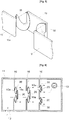
FIG. 6 is a schematic view showing an example of abaffle compartment 11 in which variable apparatuses for separating oil from blow-by gas are installed. - As shown in
FIG. 6 ,several partition walls 10 may be provided in thebaffle compartment 11. One or at least twocovers 20 andelastic members 30 may be installed in eachpartition wall 10. - Therefore, blow-by gas, which is drawn into the
baffle compartment 11 through aninlet 12, passes through the several passingholes 10a of thepartition walls 10. During this process, oil is separated from the blow-by gas both by theelastic members 30 and by thecovers 20. Thereafter, the blow-by gas is supplied into the intake system of the engine through anoutlet 13 of thebaffle compartment 11. - Here, the design of the numbers and the positions of the
partition walls 10, thecovers 20 and theelastic members 30 may be variously changed depending on the outflow rate of blow-by gas, the shape of thebaffle compartment 11, and the characteristics of the engine. - For example, as shown in
FIG. 7 ,partition walls 10 may be constructed in abaffle compartment 11 in the same manner as that of thepartition walls 4 of theconventional baffle compartment 1 ofFIG. 1 . Thecovers 20 and theelastic members 30 of the present invention are installed insuch partition walls 10. This variable apparatus for separating oil from blow-by gas is constructed such that thecovers 20 maintain the closed state when the engine is operating at low speed, and only when the engine is operating at high speed are thecovers 20 opened. When the engine is running at a low speed, even though thecovers 20 are closed, because the amount of blow-by gas is relatively small, blow-by gas can sufficiently pass through the space defined between thepartition walls 10, and oil can be reliably separated from the blow-by gas. - When the engine is running at a high speed, the amount of blow-by gas is increased. In response to this, the
covers 20 are opened, so that blow-by gas passes through the space defined between the partition walls and, simultaneously, passes through the passingholes 10a, which form bypass passages. Therefore, oil can be reliably separated from the blow-by gas. - Embodiment
- The operation of the second embodiment of the present invention for increasing the oil separation efficiency is conducted in a manner opposite to that of the example above.
- In detail, in the case of the example described above, when blow-by gas flows at low speed, oil is separated from the blow-by gas by its own weight. However, depending on changes in parameters, such as the operating conditions of the vehicle, the kind of oil and the characteristics of the engine, the case in which, when blow-by gas flows at low speed, oil is not as easily separated from the blow-by gas as when the blow-by gas flows at high speed, may arise.
- The embodiment makes it possible to easily separate oil from blow-by gas even in the above-mentioned case.
- Hereinafter, the embodiment of the present invention will be described in detail with reference to
FIGS. 8 through 10 . - As shown in
FIG. 8 , the general construction of the embodiment is similar to that of the example above. However, unlike the example above, in which, when the pressure of blow-by gas is increased, that is, when the engine is operating at high speed, thecover 20 that closes the passinghole 10a under normal conditions is spaced apart from the passinghole 10a, and in which, when the pressure of blow-by gas is reduced, that is, when the engine enters the low-speed state, thecover 20 is returned to its original state by the elasticity of theelastic members 30, in the second embodiment, when blow-by gas flows at low speed, thecover 20 maintains its position spaced apart from a passinghole 10a, when blow-by gas flows at high speed, thecover 20 closes the passinghole 10a, and when blow-by gas flows at low speed again, thecover 20 is returned to its original state, that is, to the spaced apart position, by the elasticity ofelastic members 40. - That is, the
elastic member 40 of the embodiment is biased in the opposite direction as theelastic member 30 of the example above. - In the embodiment having the above-mentioned construction, when operating at low speed, blow-by gas is rotated and accelerated while passing through the passing
holes 10a of thepartition walls 10 and between thepartition walls 10, thereby the efficiency at which oil is separated from blow-by gas is increased. - The well-known phenomenon stating that fluid flowing in a large flow area increases in speed when entering a small flow area is known as Bernoulli's theorem.
- In other words, when blow-by gas that flows in a large flow area passes through the relatively narrow passage defined between the
cover 20 and the passinghole 10a, the speed of the blow-by gas is increased. Thanks to this principle, even in the condition in which oil is not easily separated from blow-by gas when the engine is operating at low speed, this embodiment can achieve the purpose of increasing the efficiency at which oil is separated from blow-by gas. - Meanwhile, each
elastic member 40 has a shape such that it is twisted into a spiral having a predetermined angle. Theelastic member 40 serves to spirally otate and accelerate blow-by gas. Therefore, in the same manner as the example above, the efficiency at which oil is separated from blow-by gas is further increased by the increased speed and rotation of blow-by gas. - Flow guides 41, which guide the flow of blow-by gas, protrude from the
elasticity member 40, so that, when blow-by gas flows along the flow guides 41, the rotation thereof is further accelerated. - As describe above, in the second embodiment, blow-by gas, which flows at low speed, is rotated and accelerated by the
elastic members 40, which elastically maintain the distance between thecover 20 and the blow-bygas hole 10a, thus increasing the efficiency at which oil is separated from blow-by gas. Hereinafter, the fact, in which, even when blow-by gas flows at high speed, the efficiency at which oil is separated from blow-by gas can be increased in response to this, will be explained. - As shown in
FIGS. 9 and 10 , when blow-by gas flows at high speed, the pressure at which blow-by gas pushes thecover 20 increases. When high-speed blow-by gas overcomes the elasticity of theelastic members 40, which space thecover 20 apart from the passinghole 10a, thecover 20 is moved by the pressure of the blow-by gas towards the passinghole 10a and thus closes the passinghole 10a.FIG. 9 illustrates thecover 20 moved towards the passinghole 10a by blow-by gas, the flow speed of which is increased.FIG. 10 illustrates the passinghole 10a, which is completely covered with thecover 20 by the increased pressure of the blow-by gas. - Thanks to this structure, even when blow-by gas flows at high speed, the efficiency at which oil is separated from blow-by gas can be increased.
- In detail, when blow-by gas strikes the
cover 20 at high speed, thecover 20 moves towards the passinghole 10a and closes it. Then, the area of thepartition wall 10 that is struck by the blow-by gas is increased. As a result, the oil separating efficiency is increased by the increased area of thepartition wall 10. Here, as the shape of theelastic member 40 is changed, because the gap between thepartition wall 10 and thecover 20 is reduced, acceleration and rotary flow of blow-by gas are induced, so that the oil separating efficiency can be further increased. Furthermore, during the process in which thecover 20 is moved towards the passinghole 10a while overcoming the elasticity of theelastic member 40, the energy of high-speed blow-by gas is reduced. Therefore, there is an advantage in that blow-by gas is prevented from entering the intake hole of the engine in a state in which oil is not separated from the blow-by gas. - In other words, in the embodiment, in the case where the engine is running at a low speed, the oil separating efficiency can be enhanced by the acceleration of blow-by gas, and, in the case where the engine is running at a high speed, the oil separating efficiency can be enhanced by increasing the area over which the blow-by gas strikes the
partition wall 10. - Meanwhile, in the variable apparatus of the embodiment of the present invention, the pressure in a crankcase, into which oil separated from blow-by gas is moved, can be controlled.
- In detail, when the engine is running at a low speed, the
cover 20 maintains the state of being spaced apart from the passinghole 10a, so that the difference in the pressure of blow-by gas is minimized. - In other words, because the negative pressure difference applied to the blow-by gas is minimized, positive pressure is prevented from being applied to the crankcase.
- Meanwhile, when the engine is running at a high speed, the difference in pressure of blow-by gas is increased while the blow-by gas overcomes the elasticity of the
elastic member 40. This makes it possible to reduce the negative pressure applied to the crankcase to within desired conditions, for example, a predetermined design value. - As describe above, like the first embodiment, the variable apparatus for separating oil from blow-by gas according to the embodiment can reliably conduct the variable oil separating function using the
elastic members 30 having simple structures, even without a separate actuator or controller, such as that used in the conventional art. Furthermore, because the length of the passage along which the blow-by gas contacts theelastic members 30 is variable, the oil separating ability can be markedly increased. - Meanwhile, as shown in
FIG. 11 , in the embodiment,several partition walls 10 may be provided in abaffle compartment 11, and one or at least twocovers 20 andelastic members 30 may be installed in eachpartition wall 10, in the same manner as in the first embodiment. - Therefore, blow-by gas, which is drawn into the
baffle compartment 11 through aninlet 12, passes through the several passingholes 10a of thepartition walls 10. During this process, oil is separated from the blow-by gas by theelastic members 30 and thecovers 20. Thereafter, the blow-by gas is supplied into an intake system of the engine through anoutlet 13 of thebaffle compartment 11. - Here, the design of the numbers and the positions of the
partition walls 10, thecovers 20 and theelastic members 30 may be variously changed depending on the outflow rate of the blow-by gas, the shape of thebaffle compartment 11, and the characteristics of the engine. - Furthermore, as shown in
FIG. 12 , as in the embodiment,partition walls 10 according to the embodiment of the present invention may be constructed in abaffle compartment 11 in the same manner as that of thepartition walls 4 of theconventional baffle compartment 1 ofFIG. 1 . Thecovers 20 and theelastic members 30 of the embodiment of the present invention are installed insuch partition walls 10. The variable apparatus for separating oil from blow-by gas according to the embodiment having the above-mentioned structure is constructed such that, when the engine is operating at low speed, thecovers 20 maintain the open state, and, when the engine is operating at high speed, thecovers 20 are closed. When the engine is running at a low speed, blow-by gas is accelerated in the state in which thecovers 20 are open, thus increasing the efficiency at which oil is separated from blow-by gas. - When the engine is running at a high speed, because blow-by gas flows at high speed, the
covers 30 are moved towards the passingholes 10a and thus close the passingholes 10a, so that the area of thepartition walls 10 that is struck by the blow-by gas is increased, thereby increasing the efficiency at which oil is separated from blow-by gas. - As described above, the present invention provides a variable apparatus for separating oil from blow-by gas in an engine which appropriately responds to the speed at which blow-by gas flows, so that the efficiency of separation of oil from blow-by gas can be increased even when the blow-by gas flows at a high speed. Furthermore, in the present invention, because an elastic member having a spiral shape has a simple structure and the number of parts is reduced, the reliability of the assembled apparatus is enhanced, the cost of manufacturing the apparatus is reduced, and the durability thereof is markedly enhanced. In addition, in response to the pressure of blow-by gas, the elastic member extends or contracts and thus guides the rotary flow of blow-by gas and, simultaneously, the shape of the contact surface with the blow-by gas is changed, so that the ability to separate oil from blow-by gas can be increased.
Claims (3)
- A variable apparatus for separating oil from blow-by gas to be provided in a baffle compartment (11) of a cylinder head cover of an engine, and comprising; a partition wall (10), with a blow -by gas passing hole formed through the partition wall; a cover (20) having a shape corresponding to a shape of the blow-by gas passing hole (10a) to close the blow-by gas passing hole (10a), and spaced apart from the blow-by gas passing hole (10a) by a predetermined distance; and an elastic member (40) provided between the partition wall (10) and the cover and controlling a position of the cover (20) using elasticity thereof, wherein, when pressure of the blow-by gas drawn from the engine is increased, the cover (20) is moved to the partition wall (10), and, when the pressure of the blow-by gas is reduced, the elastic member is returned to an original state thereof so that the cover (20) is moved away from the partition wall (10),
characterized in that,
wherein the elastic member (30; 40) comprises a spiral elastic plate having a surface twisted into a spiral having a predetermined angle, so that, when the spiral elastic plate is elastically extended, the blow-by gas is spirally rotated under guidance of the spiral elastic plate, and
wherein a flow guide (41) is provided on the twisted surface of the spiral elastic plate to guide the blow-by gas such that the rotary flow of the blow-by gas is further accelerated. - The variable apparatus according to claim 1, wherein the elastic member comprises at least two elastic members symmetrically provided on opposite sides of the blow-by gas passing hole of the partition wall.
- The variable apparatus according to claim 1, wherein the at least one partition wall, the at least one cover and the at least one elastic member are provided in the baffle compartment.
Applications Claiming Priority (3)
| Application Number | Priority Date | Filing Date | Title |
|---|---|---|---|
| KR20050133170 | 2005-12-29 | ||
| KR1020060131114A KR100979570B1 (en) | 2006-12-20 | 2006-12-20 | Variable oil separator of engine blow-by gas |
| PCT/KR2006/005691 WO2007075018A1 (en) | 2005-12-29 | 2006-12-26 | Apparatus for separating oil from blow-by gas of engine |
Publications (3)
| Publication Number | Publication Date |
|---|---|
| EP1966466A1 EP1966466A1 (en) | 2008-09-10 |
| EP1966466A4 EP1966466A4 (en) | 2010-11-24 |
| EP1966466B1 true EP1966466B1 (en) | 2012-04-11 |
Family
ID=38218211
Family Applications (1)
| Application Number | Title | Priority Date | Filing Date |
|---|---|---|---|
| EP06835395A Not-in-force EP1966466B1 (en) | 2005-12-29 | 2006-12-26 | Apparatus for separating oil from blow-by gas of engine |
Country Status (5)
| Country | Link |
|---|---|
| US (1) | US7938875B2 (en) |
| EP (1) | EP1966466B1 (en) |
| JP (1) | JP4971360B2 (en) |
| AT (1) | ATE553286T1 (en) |
| WO (1) | WO2007075018A1 (en) |
Cited By (1)
| Publication number | Priority date | Publication date | Assignee | Title |
|---|---|---|---|---|
| DE102015223301A1 (en) * | 2015-11-25 | 2017-06-01 | Borgward Trademark Holdings Gmbh | OIL AND GAS SEPARATOR, A MOTOR AND A VEHICLE WITH THIS |
Families Citing this family (29)
| Publication number | Priority date | Publication date | Assignee | Title |
|---|---|---|---|---|
| US7941213B2 (en) * | 2006-12-28 | 2011-05-10 | Medtronic, Inc. | System and method to evaluate electrode position and spacing |
| CN101711125B (en) | 2007-04-18 | 2016-03-16 | 美敦力公司 | Long-term implantable active fixed medical electronic leads for non-fluoroscopy implants |
| US8260395B2 (en) | 2008-04-18 | 2012-09-04 | Medtronic, Inc. | Method and apparatus for mapping a structure |
| US8532734B2 (en) | 2008-04-18 | 2013-09-10 | Regents Of The University Of Minnesota | Method and apparatus for mapping a structure |
| US8494608B2 (en) | 2008-04-18 | 2013-07-23 | Medtronic, Inc. | Method and apparatus for mapping a structure |
| US8340751B2 (en) * | 2008-04-18 | 2012-12-25 | Medtronic, Inc. | Method and apparatus for determining tracking a virtual point defined relative to a tracked member |
| US8663120B2 (en) * | 2008-04-18 | 2014-03-04 | Regents Of The University Of Minnesota | Method and apparatus for mapping a structure |
| US8839798B2 (en) * | 2008-04-18 | 2014-09-23 | Medtronic, Inc. | System and method for determining sheath location |
| US8175681B2 (en) | 2008-12-16 | 2012-05-08 | Medtronic Navigation Inc. | Combination of electromagnetic and electropotential localization |
| US8494614B2 (en) | 2009-08-31 | 2013-07-23 | Regents Of The University Of Minnesota | Combination localization system |
| US8494613B2 (en) | 2009-08-31 | 2013-07-23 | Medtronic, Inc. | Combination localization system |
| US8355774B2 (en) * | 2009-10-30 | 2013-01-15 | Medtronic, Inc. | System and method to evaluate electrode position and spacing |
| JP5475424B2 (en) | 2009-12-16 | 2014-04-16 | 株式会社マーレ フィルターシステムズ | Oil mist separator |
| JP5969191B2 (en) * | 2011-10-17 | 2016-08-17 | 日野自動車株式会社 | Breather oil mist aggregation promoting structure |
| FR2989995B1 (en) | 2012-04-25 | 2015-11-20 | S T E E P | OIL DECANTATION SYSTEM CONTAINED IN CARTER GASES OF A MOTOR VEHICLE ENGINE |
| US8887705B2 (en) * | 2012-05-23 | 2014-11-18 | Honda Motor Co., Ltd. | Head cover baffle system for improving oil mist separation |
| US9138671B2 (en) * | 2012-08-30 | 2015-09-22 | Cummins Filtration Ip, Inc. | Inertial gas-liquid separator and porous collection substrate for use in inertial gas-liquid separator |
| US9669139B2 (en) | 2013-03-14 | 2017-06-06 | Kci Licensing, Inc. | Fluid collection canister with integrated moisture trap |
| JP6146202B2 (en) * | 2013-08-22 | 2017-06-14 | トヨタ紡織株式会社 | Oil mist separator |
| JP6010011B2 (en) * | 2013-11-08 | 2016-10-19 | 本田技研工業株式会社 | Breather system for internal combustion engines |
| US10533470B2 (en) | 2013-11-08 | 2020-01-14 | Honda Motor Co., Ltd. | Oil separation device for internal combustion engine |
| US9682336B2 (en) * | 2014-05-28 | 2017-06-20 | Ingersoll-Rand Company | Impact moisture separator |
| FR3033503B1 (en) * | 2015-03-10 | 2019-05-24 | Filtrauto | DEVICE FOR SEPARATING CARTER GAS OIL FROM AN INTERNAL COMBUSTION ENGINE |
| US9260993B1 (en) * | 2015-07-22 | 2016-02-16 | UPR Products, Inc. | Oil and air separator system and method |
| JP7159745B2 (en) * | 2018-09-25 | 2022-10-25 | トヨタ自動車株式会社 | Oil separation equipment and vacuum die casting equipment |
| CH717661A1 (en) | 2020-07-15 | 2022-01-31 | Liebherr Machines Bulle Sa | Aerosol separator for separating aerosols in a blow-by gas. |
| US11691771B1 (en) * | 2022-03-02 | 2023-07-04 | Moshe Epstein | Hygienic conveying chain clamp used in a horizontal form fill and seal packaging machine |
| US12110976B2 (en) * | 2022-12-05 | 2024-10-08 | Relativity Space, Inc. | Valves and valve assemblies |
| CN115970120B (en) * | 2022-12-16 | 2025-01-14 | 深圳融昕医疗科技有限公司 | One-way valve for ventilator |
Family Cites Families (12)
| Publication number | Priority date | Publication date | Assignee | Title |
|---|---|---|---|---|
| JPS5732247Y2 (en) * | 1978-11-16 | 1982-07-15 | ||
| US4633388A (en) * | 1984-01-18 | 1986-12-30 | Siemens Corporate Research & Support, Inc. | On-chip microprocessor instruction decoder having hardware for selectively bypassing on-chip circuitry used to decipher encrypted instruction codes |
| JPH07243318A (en) | 1994-02-28 | 1995-09-19 | Tsuchiya Mfg Co Ltd | Oil mist separator |
| JPH10176518A (en) | 1996-12-18 | 1998-06-30 | Fuji Heavy Ind Ltd | Gas-liquid separating device for engine of vibrator |
| JPH11210436A (en) * | 1998-01-23 | 1999-08-03 | Kubota Corp | Breather device for overhead cam type vertical engine |
| DE10127817A1 (en) * | 2001-06-07 | 2002-12-12 | Bosch Gmbh Robert | Oil separating device has oil drain aperture in flow or cascade device before cyclone separating device |
| CN1426734A (en) | 2001-12-18 | 2003-07-02 | 乐金电子(天津)电器有限公司 | Dust collector box of vacuum cleaner |
| US7080636B2 (en) * | 2003-05-05 | 2006-07-25 | Dichtungstechnik G. Bruss Gmbh & Co. Kg | Oil separating device for a combustion engine |
| JP2005005909A (en) * | 2003-06-10 | 2005-01-06 | Sony Ericsson Mobilecommunications Japan Inc | Competition management program, storage medium stored with competition management program, competition management method and electronic apparatus |
| KR100521207B1 (en) | 2003-11-11 | 2005-10-17 | 현대자동차주식회사 | oil separator from blow-by gas |
| JP2005201080A (en) | 2004-01-13 | 2005-07-28 | Toyota Industries Corp | Cylinder head cover |
| DE202004009673U1 (en) * | 2004-05-05 | 2005-09-15 | Hengst Gmbh & Co Kg | Valve arrangement in a crankcase ventilation |
-
2006
- 2006-12-26 WO PCT/KR2006/005691 patent/WO2007075018A1/en not_active Ceased
- 2006-12-26 JP JP2008548409A patent/JP4971360B2/en not_active Expired - Fee Related
- 2006-12-26 AT AT06835395T patent/ATE553286T1/en active
- 2006-12-26 EP EP06835395A patent/EP1966466B1/en not_active Not-in-force
- 2006-12-26 US US12/159,707 patent/US7938875B2/en not_active Expired - Fee Related
Cited By (2)
| Publication number | Priority date | Publication date | Assignee | Title |
|---|---|---|---|---|
| DE102015223301A1 (en) * | 2015-11-25 | 2017-06-01 | Borgward Trademark Holdings Gmbh | OIL AND GAS SEPARATOR, A MOTOR AND A VEHICLE WITH THIS |
| DE102015223301B4 (en) * | 2015-11-25 | 2017-12-14 | Borgward Trademark Holdings Gmbh | OIL AND GAS SEPARATOR, A MOTOR AND A VEHICLE WITH THIS |
Also Published As
| Publication number | Publication date |
|---|---|
| JP2009522486A (en) | 2009-06-11 |
| EP1966466A1 (en) | 2008-09-10 |
| US20090126575A1 (en) | 2009-05-21 |
| ATE553286T1 (en) | 2012-04-15 |
| JP4971360B2 (en) | 2012-07-11 |
| EP1966466A4 (en) | 2010-11-24 |
| WO2007075018A1 (en) | 2007-07-05 |
| US7938875B2 (en) | 2011-05-10 |
Similar Documents
| Publication | Publication Date | Title |
|---|---|---|
| US7938875B2 (en) | Apparatus for separating oil from blow-by gas of engine | |
| EP2653678B1 (en) | Separator device for use in a system for the recirculation of blow-by gases of an internal combustion engine | |
| US6942709B2 (en) | Switchable cyclone for separating particles or droplets from a fluid stream | |
| US9816410B2 (en) | Separator device for a system for recirculation of the blow-by gases of an internal combustion engine | |
| US20110030629A1 (en) | Separator for a Crankcase Ventilation of an Internal Combustion Engine | |
| KR20090084542A (en) | Variable Turbocharger and Variable Turbocharger Control Method | |
| JP5290732B2 (en) | Oil separator for internal combustion engine | |
| JP2006505732A (en) | Apparatus for separating liquid from a gas stream | |
| CN105705739B (en) | Controllable oil separation equipment | |
| SE524273C2 (en) | Two-stroke internal combustion engine | |
| KR20140002613A (en) | Hollow body having an integrated oil separating device | |
| JPS5840649B2 (en) | benzouchi | |
| US11149601B2 (en) | Oil separator having first and second gas inlets and gas outlets | |
| KR102454615B1 (en) | Impacter type breather | |
| CN1594861A (en) | Intake arrangement for an internal combustion engine | |
| CN101351627A (en) | Device for separating oil from blow-by gas of an engine | |
| JP6001407B2 (en) | Oil separator | |
| KR100979570B1 (en) | Variable oil separator of engine blow-by gas | |
| KR101297875B1 (en) | Solenoid ball valve with bypass orifice | |
| US20090188478A1 (en) | Crankcase for internal combustion engine | |
| KR101006814B1 (en) | Blow-by gas oil separator | |
| JP2010121563A (en) | Pressure adjusting device | |
| JP2007009746A (en) | Oil mist processing equipment | |
| JP5333251B2 (en) | Variable compression ratio internal combustion engine | |
| KR100240716B1 (en) | Valves for automotive engines |
Legal Events
| Date | Code | Title | Description |
|---|---|---|---|
| PUAI | Public reference made under article 153(3) epc to a published international application that has entered the european phase |
Free format text: ORIGINAL CODE: 0009012 |
|
| 17P | Request for examination filed |
Effective date: 20080627 |
|
| AK | Designated contracting states |
Kind code of ref document: A1 Designated state(s): AT BE BG CH CY CZ DE DK EE ES FI FR GB GR HU IE IS IT LI LT LU LV MC NL PL PT RO SE SI SK TR |
|
| A4 | Supplementary search report drawn up and despatched |
Effective date: 20101027 |
|
| RIC1 | Information provided on ipc code assigned before grant |
Ipc: G05D 7/01 20060101ALI20101021BHEP Ipc: F16K 15/02 20060101ALI20101021BHEP Ipc: F16K 7/12 20060101ALI20101021BHEP Ipc: F01M 13/04 20060101AFI20070820BHEP Ipc: F16K 15/14 20060101ALI20101021BHEP |
|
| 17Q | First examination report despatched |
Effective date: 20110614 |
|
| RIC1 | Information provided on ipc code assigned before grant |
Ipc: F16K 15/02 20060101ALI20110905BHEP Ipc: F16K 7/12 20060101ALI20110905BHEP Ipc: F16K 15/14 20060101ALI20110905BHEP Ipc: G05D 7/01 20060101ALI20110905BHEP Ipc: F01M 13/04 20060101AFI20110905BHEP |
|
| GRAP | Despatch of communication of intention to grant a patent |
Free format text: ORIGINAL CODE: EPIDOSNIGR1 |
|
| DAX | Request for extension of the european patent (deleted) | ||
| GRAS | Grant fee paid |
Free format text: ORIGINAL CODE: EPIDOSNIGR3 |
|
| GRAA | (expected) grant |
Free format text: ORIGINAL CODE: 0009210 |
|
| AK | Designated contracting states |
Kind code of ref document: B1 Designated state(s): AT BE BG CH CY CZ DE DK EE ES FI FR GB GR HU IE IS IT LI LT LU LV MC NL PL PT RO SE SI SK TR |
|
| REG | Reference to a national code |
Ref country code: GB Ref legal event code: FG4D |
|
| REG | Reference to a national code |
Ref country code: CH Ref legal event code: EP |
|
| REG | Reference to a national code |
Ref country code: AT Ref legal event code: REF Ref document number: 553286 Country of ref document: AT Kind code of ref document: T Effective date: 20120415 |
|
| REG | Reference to a national code |
Ref country code: IE Ref legal event code: FG4D |
|
| REG | Reference to a national code |
Ref country code: DE Ref legal event code: R096 Ref document number: 602006028863 Country of ref document: DE Effective date: 20120606 |
|
| REG | Reference to a national code |
Ref country code: NL Ref legal event code: VDEP Effective date: 20120411 |
|
| REG | Reference to a national code |
Ref country code: AT Ref legal event code: MK05 Ref document number: 553286 Country of ref document: AT Kind code of ref document: T Effective date: 20120411 |
|
| LTIE | Lt: invalidation of european patent or patent extension |
Effective date: 20120411 |
|
| PG25 | Lapsed in a contracting state [announced via postgrant information from national office to epo] |
Ref country code: IS Free format text: LAPSE BECAUSE OF FAILURE TO SUBMIT A TRANSLATION OF THE DESCRIPTION OR TO PAY THE FEE WITHIN THE PRESCRIBED TIME-LIMIT Effective date: 20120811 Ref country code: CY Free format text: LAPSE BECAUSE OF FAILURE TO SUBMIT A TRANSLATION OF THE DESCRIPTION OR TO PAY THE FEE WITHIN THE PRESCRIBED TIME-LIMIT Effective date: 20120411 Ref country code: PL Free format text: LAPSE BECAUSE OF FAILURE TO SUBMIT A TRANSLATION OF THE DESCRIPTION OR TO PAY THE FEE WITHIN THE PRESCRIBED TIME-LIMIT Effective date: 20120411 Ref country code: SE Free format text: LAPSE BECAUSE OF FAILURE TO SUBMIT A TRANSLATION OF THE DESCRIPTION OR TO PAY THE FEE WITHIN THE PRESCRIBED TIME-LIMIT Effective date: 20120411 Ref country code: LT Free format text: LAPSE BECAUSE OF FAILURE TO SUBMIT A TRANSLATION OF THE DESCRIPTION OR TO PAY THE FEE WITHIN THE PRESCRIBED TIME-LIMIT Effective date: 20120411 Ref country code: FI Free format text: LAPSE BECAUSE OF FAILURE TO SUBMIT A TRANSLATION OF THE DESCRIPTION OR TO PAY THE FEE WITHIN THE PRESCRIBED TIME-LIMIT Effective date: 20120411 |
|
| PG25 | Lapsed in a contracting state [announced via postgrant information from national office to epo] |
Ref country code: LV Free format text: LAPSE BECAUSE OF FAILURE TO SUBMIT A TRANSLATION OF THE DESCRIPTION OR TO PAY THE FEE WITHIN THE PRESCRIBED TIME-LIMIT Effective date: 20120411 Ref country code: GR Free format text: LAPSE BECAUSE OF FAILURE TO SUBMIT A TRANSLATION OF THE DESCRIPTION OR TO PAY THE FEE WITHIN THE PRESCRIBED TIME-LIMIT Effective date: 20120712 Ref country code: PT Free format text: LAPSE BECAUSE OF FAILURE TO SUBMIT A TRANSLATION OF THE DESCRIPTION OR TO PAY THE FEE WITHIN THE PRESCRIBED TIME-LIMIT Effective date: 20120813 Ref country code: SI Free format text: LAPSE BECAUSE OF FAILURE TO SUBMIT A TRANSLATION OF THE DESCRIPTION OR TO PAY THE FEE WITHIN THE PRESCRIBED TIME-LIMIT Effective date: 20120411 |
|
| PG25 | Lapsed in a contracting state [announced via postgrant information from national office to epo] |
Ref country code: BE Free format text: LAPSE BECAUSE OF FAILURE TO SUBMIT A TRANSLATION OF THE DESCRIPTION OR TO PAY THE FEE WITHIN THE PRESCRIBED TIME-LIMIT Effective date: 20120411 |
|
| PG25 | Lapsed in a contracting state [announced via postgrant information from national office to epo] |
Ref country code: CZ Free format text: LAPSE BECAUSE OF FAILURE TO SUBMIT A TRANSLATION OF THE DESCRIPTION OR TO PAY THE FEE WITHIN THE PRESCRIBED TIME-LIMIT Effective date: 20120411 Ref country code: AT Free format text: LAPSE BECAUSE OF FAILURE TO SUBMIT A TRANSLATION OF THE DESCRIPTION OR TO PAY THE FEE WITHIN THE PRESCRIBED TIME-LIMIT Effective date: 20120411 Ref country code: NL Free format text: LAPSE BECAUSE OF FAILURE TO SUBMIT A TRANSLATION OF THE DESCRIPTION OR TO PAY THE FEE WITHIN THE PRESCRIBED TIME-LIMIT Effective date: 20120411 Ref country code: EE Free format text: LAPSE BECAUSE OF FAILURE TO SUBMIT A TRANSLATION OF THE DESCRIPTION OR TO PAY THE FEE WITHIN THE PRESCRIBED TIME-LIMIT Effective date: 20120411 Ref country code: SK Free format text: LAPSE BECAUSE OF FAILURE TO SUBMIT A TRANSLATION OF THE DESCRIPTION OR TO PAY THE FEE WITHIN THE PRESCRIBED TIME-LIMIT Effective date: 20120411 Ref country code: DK Free format text: LAPSE BECAUSE OF FAILURE TO SUBMIT A TRANSLATION OF THE DESCRIPTION OR TO PAY THE FEE WITHIN THE PRESCRIBED TIME-LIMIT Effective date: 20120411 Ref country code: RO Free format text: LAPSE BECAUSE OF FAILURE TO SUBMIT A TRANSLATION OF THE DESCRIPTION OR TO PAY THE FEE WITHIN THE PRESCRIBED TIME-LIMIT Effective date: 20120411 |
|
| PLBE | No opposition filed within time limit |
Free format text: ORIGINAL CODE: 0009261 |
|
| STAA | Information on the status of an ep patent application or granted ep patent |
Free format text: STATUS: NO OPPOSITION FILED WITHIN TIME LIMIT |
|
| PG25 | Lapsed in a contracting state [announced via postgrant information from national office to epo] |
Ref country code: IT Free format text: LAPSE BECAUSE OF FAILURE TO SUBMIT A TRANSLATION OF THE DESCRIPTION OR TO PAY THE FEE WITHIN THE PRESCRIBED TIME-LIMIT Effective date: 20120411 |
|
| 26N | No opposition filed |
Effective date: 20130114 |
|
| PG25 | Lapsed in a contracting state [announced via postgrant information from national office to epo] |
Ref country code: ES Free format text: LAPSE BECAUSE OF FAILURE TO SUBMIT A TRANSLATION OF THE DESCRIPTION OR TO PAY THE FEE WITHIN THE PRESCRIBED TIME-LIMIT Effective date: 20120722 |
|
| REG | Reference to a national code |
Ref country code: DE Ref legal event code: R097 Ref document number: 602006028863 Country of ref document: DE Effective date: 20130114 |
|
| PG25 | Lapsed in a contracting state [announced via postgrant information from national office to epo] |
Ref country code: MC Free format text: LAPSE BECAUSE OF NON-PAYMENT OF DUE FEES Effective date: 20121231 Ref country code: BG Free format text: LAPSE BECAUSE OF FAILURE TO SUBMIT A TRANSLATION OF THE DESCRIPTION OR TO PAY THE FEE WITHIN THE PRESCRIBED TIME-LIMIT Effective date: 20120711 |
|
| REG | Reference to a national code |
Ref country code: CH Ref legal event code: PL |
|
| GBPC | Gb: european patent ceased through non-payment of renewal fee |
Effective date: 20121226 |
|
| REG | Reference to a national code |
Ref country code: IE Ref legal event code: MM4A |
|
| REG | Reference to a national code |
Ref country code: FR Ref legal event code: ST Effective date: 20130830 |
|
| REG | Reference to a national code |
Ref country code: DE Ref legal event code: R119 Ref document number: 602006028863 Country of ref document: DE Effective date: 20130702 |
|
| PG25 | Lapsed in a contracting state [announced via postgrant information from national office to epo] |
Ref country code: IE Free format text: LAPSE BECAUSE OF NON-PAYMENT OF DUE FEES Effective date: 20121226 Ref country code: CH Free format text: LAPSE BECAUSE OF NON-PAYMENT OF DUE FEES Effective date: 20121231 Ref country code: LI Free format text: LAPSE BECAUSE OF NON-PAYMENT OF DUE FEES Effective date: 20121231 Ref country code: DE Free format text: LAPSE BECAUSE OF NON-PAYMENT OF DUE FEES Effective date: 20130702 |
|
| PG25 | Lapsed in a contracting state [announced via postgrant information from national office to epo] |
Ref country code: GB Free format text: LAPSE BECAUSE OF NON-PAYMENT OF DUE FEES Effective date: 20121226 Ref country code: FR Free format text: LAPSE BECAUSE OF NON-PAYMENT OF DUE FEES Effective date: 20130102 |
|
| PG25 | Lapsed in a contracting state [announced via postgrant information from national office to epo] |
Ref country code: TR Free format text: LAPSE BECAUSE OF FAILURE TO SUBMIT A TRANSLATION OF THE DESCRIPTION OR TO PAY THE FEE WITHIN THE PRESCRIBED TIME-LIMIT Effective date: 20120411 |
|
| PG25 | Lapsed in a contracting state [announced via postgrant information from national office to epo] |
Ref country code: LU Free format text: LAPSE BECAUSE OF NON-PAYMENT OF DUE FEES Effective date: 20121226 |
|
| PG25 | Lapsed in a contracting state [announced via postgrant information from national office to epo] |
Ref country code: HU Free format text: LAPSE BECAUSE OF FAILURE TO SUBMIT A TRANSLATION OF THE DESCRIPTION OR TO PAY THE FEE WITHIN THE PRESCRIBED TIME-LIMIT Effective date: 20061226 |