EP1965104A2 - Shift-by-wire system - Google Patents
Shift-by-wire system Download PDFInfo
- Publication number
- EP1965104A2 EP1965104A2 EP08003285A EP08003285A EP1965104A2 EP 1965104 A2 EP1965104 A2 EP 1965104A2 EP 08003285 A EP08003285 A EP 08003285A EP 08003285 A EP08003285 A EP 08003285A EP 1965104 A2 EP1965104 A2 EP 1965104A2
- Authority
- EP
- European Patent Office
- Prior art keywords
- rotational position
- electric motor
- actual rotational
- shift
- shift command
- Prior art date
- Legal status (The legal status is an assumption and is not a legal conclusion. Google has not performed a legal analysis and makes no representation as to the accuracy of the status listed.)
- Granted
Links
Images


Classifications
-
- F—MECHANICAL ENGINEERING; LIGHTING; HEATING; WEAPONS; BLASTING
- F16—ENGINEERING ELEMENTS AND UNITS; GENERAL MEASURES FOR PRODUCING AND MAINTAINING EFFECTIVE FUNCTIONING OF MACHINES OR INSTALLATIONS; THERMAL INSULATION IN GENERAL
- F16H—GEARING
- F16H61/00—Control functions within control units of change-speed- or reversing-gearings for conveying rotary motion ; Control of exclusively fluid gearing, friction gearing, gearings with endless flexible members or other particular types of gearing
- F16H61/26—Generation or transmission of movements for final actuating mechanisms
- F16H61/28—Generation or transmission of movements for final actuating mechanisms with at least one movement of the final actuating mechanism being caused by a non-mechanical force, e.g. power-assisted
- F16H61/32—Electric motors actuators or related electrical control means therefor
- F16H2061/326—Actuators for range selection, i.e. actuators for controlling the range selector or the manual range valve in the transmission
-
- F—MECHANICAL ENGINEERING; LIGHTING; HEATING; WEAPONS; BLASTING
- F16—ENGINEERING ELEMENTS AND UNITS; GENERAL MEASURES FOR PRODUCING AND MAINTAINING EFFECTIVE FUNCTIONING OF MACHINES OR INSTALLATIONS; THERMAL INSULATION IN GENERAL
- F16H—GEARING
- F16H2306/00—Shifting
- F16H2306/24—Interruption of shift, e.g. if new shift is initiated during ongoing previous shift
-
- F—MECHANICAL ENGINEERING; LIGHTING; HEATING; WEAPONS; BLASTING
- F16—ENGINEERING ELEMENTS AND UNITS; GENERAL MEASURES FOR PRODUCING AND MAINTAINING EFFECTIVE FUNCTIONING OF MACHINES OR INSTALLATIONS; THERMAL INSULATION IN GENERAL
- F16H—GEARING
- F16H59/00—Control inputs to control units of change-speed-, or reversing-gearings for conveying rotary motion
- F16H59/02—Selector apparatus
- F16H59/08—Range selector apparatus
- F16H59/10—Range selector apparatus comprising levers
- F16H59/105—Range selector apparatus comprising levers consisting of electrical switches or sensors
-
- F—MECHANICAL ENGINEERING; LIGHTING; HEATING; WEAPONS; BLASTING
- F16—ENGINEERING ELEMENTS AND UNITS; GENERAL MEASURES FOR PRODUCING AND MAINTAINING EFFECTIVE FUNCTIONING OF MACHINES OR INSTALLATIONS; THERMAL INSULATION IN GENERAL
- F16H—GEARING
- F16H61/00—Control functions within control units of change-speed- or reversing-gearings for conveying rotary motion ; Control of exclusively fluid gearing, friction gearing, gearings with endless flexible members or other particular types of gearing
- F16H61/02—Control functions within control units of change-speed- or reversing-gearings for conveying rotary motion ; Control of exclusively fluid gearing, friction gearing, gearings with endless flexible members or other particular types of gearing characterised by the signals used
- F16H61/0262—Control functions within control units of change-speed- or reversing-gearings for conveying rotary motion ; Control of exclusively fluid gearing, friction gearing, gearings with endless flexible members or other particular types of gearing characterised by the signals used the signals being hydraulic
- F16H61/0276—Elements specially adapted for hydraulic control units, e.g. valves
- F16H61/0286—Manual valves
Definitions
- the present invention relates to a shift-by-wire system.
- the tendency toward a transition from a mechanical driving system to an electrical driving system has grown in the field of vehicles such as automobiles in order to cope with a demand for space saving or improvement in assembling efficiency or controllability.
- development of a shift-by-wire system that uses an electric motor to electrically control range switching of an automatic transmission has been under way.
- JP-A-2004-23890 As the shift-by-wire system, a system that uses a by-wire control circuit unit to control the rotation of an electric motor conformably to a shift command inputted by a user, and thus switches ranges has been disclosed in JP-A-2004-23890 .
- the system in JP-A-2004-23890 designates a target rotational position so as to realize a target range conformable to the shift command, rotates the electric motor to the target rotational position, and thus achieves range switching.
- the system in the JP-A-2004-23890 designates a new target rotational position conformable to the re-shift command.
- the responsiveness to a shift command is improved.
- the present invention addresses the foregoing and thus it is an object to provide a shift-by-wire system that improves responsiveness to a shift command and ensures safety.
- a shift-by-wire system includes an electric motor that generates a rotational output for use in switching ranges of an automatic transmission in a vehicle and a by-wire control circuit or unit that electrically controls the rotation of the electric motor to comply with a shift command inputted by a user.
- the by-wire control circuit, circuit, unit or the like modifies rotation control until the rotational position of the electric motor reaches a new target rotational position to comply with the re-shift command.
- the above described operation is performed according to the actual rotational position of the electric motor attained at the time point of input of the re-shift command.
- rotation control may be modified based on the actual rotational position of the electric motor until the rotational position of the electric motor reaches a new target rotational position. Therefore, whatever the actual rotational position of the electric motor is at the time of input of the re-shift command, the electric motor can be rotated to the new target rotational position since the rotation control takes into account the actual rotational position. As a result, the automatic transmission will not be brought to a state contradictory to an intended shift position or operation and the responsiveness of the system to a shift command can be improved.
- the rotational region of the electric motor bringing the automatic transmission to a neutral state can be defined as a neutral region.
- the by-wire control circuit controls the rotation of the electric motor so that the rotation will be null in the neutral region to which the actual rotational position belongs. Thereafter, the by-wire control circuit rotates the electric motor in the opposite direction so that the rotational position of the electric motor will reach the target rotational position.
- the rotation of the electric motor is controlled to be null in the neutral region to which the actual rotational position belongs.
- the automatic transmission is thus brought to the neutral state. Therefore, the sense of discrepancy or discomposure that might be given to a user because the automatic transmission enters a non-neutral state contradictory to a user's intention can be suppressed.
- non-neutral region which can be defined as the rotational region of the electric motor bringing the automatic transmission to the non-neutral state.
- the actual rotational position lies in the non-neutral region.
- the by-wire control circuit continues the rotation in the actual rotational direction of the electric motor so that the rotational position of the electric motor will reach the neutral region in the actual rotational direction.
- the by-wire control circuit controls the rotation of the electric motor so that the rotation will be null in the neutral region.
- the by-wire control circuit rotates the electric motor in the opposite direction so that the rotational position of the electric motor will reach the target rotational position.
- the rotation of the electric motor is controlled to be null in the neutral region, which is reached by the electric motor by continuing rotation in the actual rotational direction.
- the automatic transmission is brought to the neutral state.
- the by-wire control circuit causes the rotational position of the electric motor to reach the neutral region closest to the actual rotational position in the actual rotational direction. Since the rotational position of the electric motor is caused to immediately reach the neutral region and the rotation thereof is nullified, the time during which the automatic transmission remains in the neutral state can be shortened as greatly as possible. Consequently, the sense of discrepancy that would be given to the user because the automatic transmission remains in the neutral state for a relatively long period of time can be avoided.
- that one neutral region is, for the purposes of the present disclosure, the neutral region closest to the actual rotational position as described above.
- the by-wire control circuit controls the rotation of the electric motor so that the rotation will be null in the non-neutral region to which the actual rotational position belongs while implementing fail-safe control for ensuring vehicle safety. Thereafter, the by-wire control circuit rotates the electric motor in the opposite direction so that the rotational position of the electric motor will reach the target rotational position.
- the rotation of the electric motor is controlled to be null in the non-neutral region to which the actual rotational position belongs. Therefore, although the rotation of the electric motor is nullified in the region bringing the automatic transmission to the non-neutral state, the rotational position of the electric motor is allowed to reach the target rotational position before the rotation in the opposite direction from the actual rotational position, since vehicle safety is ensured owing to the fail-safe control, a sense of discomposure given to a user can be alleviated.
- fail-safe control is such that an engine control means for controlling the output torque of a vehicle engine decreases the output torque. Consequently, even if the rotation of the electric motor is nullified in a region that brings the automatic transmission to a non-neutral state, a sense of discomposure can be alleviated and vehicle safety can be ensured due to the decrease in the output torque of the engine.
- Fail-safe control can be further implemented in that a transmission control means, which controls the automatic transmission independently of the shift-by-wire system, fixes the automatic transmission in the neutral state. Consequently, even if the rotation of the electric motor is nullified in the region bringing the automatic transmission to the non-neutral state, a sense of discomposure can be alleviated and vehicle safety is ensured since the automatic transmission is fixed in the neutral state.
- a warning unit can be included for giving warning during fail-safe control. However, since a user is informed of the fact that fail-safe control is under way, a sense of discrepancy derived from the fail-safe control itself can be alleviated.
- non-neutral region can be characterized as the rotational region of the electric motor realizing a range of selections involving drive engagement of the automatic transmission.
- neutral region can be characterized as the rotational region of the electric motor realizing the neutral range of the automatic transmission or the parking range, or may be determined and located among multiple rotational regions of the electric motor realizing multiple ranges of the automatic transmission.
- the by-wire control circuit continues the rotation in the actual rotational direction of the electric motor so that the rotational position of the electric motor will reach the target rotational position. Consequently, when the target rotational position lies in the actual rotational direction with respect to the actual rotational position of the electric motor, the rotation in the actual rotational direction can be continued as it is so that the rotational position of the electric motor will reach the target rotational position. Therefore, responsiveness can be improved but a sense of discrepancy or discomposure will not be given to a user.
- the by-wire control circuit rejects any additional re-shift commands that exceed an upper limit, such as a predetermined limit on the number of times a re-shift command can be inputted within a certain amount of time. Consequently, heating and break down of the by-wire control circuit that electrically controls the electric motor resulting from response to an excessive number of shift commands within a certain period of time can be suppressed.
- a warning unit can give warning that a re-shift command is being rejected. Since a user is informed of the rejection of the shift command, a sense of discrepancy that might occur when the automatic transmission enters a state contradictory to the intended state due to the rejection of the shift command can be alleviated.
- Fig. 2 shows a vehicle control system 10 to which a shift-by-wire system 2 in accordance with the first embodiment of the present invention is adapted.
- the shift-by-wire system 2 or by-wire circuit, circuit, or unit can refer to individual portions of, groups of or all of the elements associated therewith and additional elements such as elements of the shifting circuit as will be described hereinafter.
- the vehicle control system 10 to be mounted in a vehicle includes the shift-by-wire system 2, an automatic transmission control system 4, and an engine control system 6.
- the automatic transmission control system 4 further includes a hydraulic circuit 44 that drives an automatic transmission 42.
- a manual valve 46 of the hydraulic circuit 44 includes a spool valve, and switches ranges of the automatic transmission 42 with an output oil pressure depending on a spool moving position.
- a neutral (N) range and a parking (P) range are supported as ranges bringing the automatic transmission to a neutral state in which an output torque of an internal combustion engine 16 in a vehicle is not transmitted to the driving wheels of the vehicle.
- a reverse (R) range and a drive (D) range are supported as running ranges that bring the automatic transmission to a non-neutral state in which the output torque of the engine 16 is transmitted to the driving wheels of the vehicle.
- Multiple electromagnetic valves 48 in the hydraulic circuit 44 fasten or release associated frictional elements (not shown) of the automatic transmission 42, whereby the shift stages of the transmission 42 are switched. Moreover, in the hydraulic circuit 44 in the present embodiment, a predetermined frictional element is released by the associated electromagnetic valve 48 irrespective of the spool moving position of the manual valve 46 in order to forcibly realize the N range.
- the transmission ECU 40 is electrically connected to the electromagnetic valves 48 and other multiple electrical elements constituting the hydraulic circuit 44, and electrically controls the actions of the electrical elements.
- the shift-by-wire system 2 further includes an actuator 21 that drives the manual valve 46 of the automatic transmission control system 4, and a conversion mechanism 22.
- an electric motor 24 includes a switched reluctance motor that generates a rotational output when in the conducting or energized state.
- a deceleration mechanism 25 includes a gear mechanism that decelerates a rotational output of the motor 24, and transmits the rotational output to the conversion mechanism 22, which converts the rotational output into a linear motion. Accordingly, the spool moving position of the manual valve 46 is switched from one position to another. Consequently, in the present embodiment, the ranges of the automatic transmission 42 are switched based on the rotational position of the electric motor 24, which, hereinafter, is referred to simply as the motor rotational position.
- the by-wire ECU 20 is electrically connected to each of the electric motor 24, a rotational position sensor 26, and a selector sensor 28.
- the rotational position sensor 26 includes, for example, a rotary encoder, and is disposed on the output side of the electric motor 24 in order to detect the motor rotational position.
- the selector sensor 28 detects a user-requested range according to a manipulation performed on a range selector 12 of the vehicle, and outputs an analog signal or a digital signal representing the detected range. Consequently, the by-wire ECU 20 stores necessary information in a memory 29, and electrically controls the rotation of the electric motor 24 on the basis of the results of detections by the sensors 26 and 28 respectively.
- the by-wire ECU 20 decides that a shift command has been inputted.
- the by-wire ECU 20 implements rotation control in the electric motor 24 to switch the ranges so that the actual motor rotational position detected by the rotational position sensor 26 will be brought to a target rotational position, which is a rotational position of the motor associated with the changed requested range.
- the by-wire ECU 20 is also electrically connected to a warning device 19 of the vehicle, and, if necessary, controls the warning device 19 so as to give a predetermined warning. Warning may be produced by displaying a warning lamp in, for example, the dashboard of the vehicle or by displaying a screen image on the monitor of the vehicle, by outputting a sound from a loudspeaker of the vehicle, or the like.
- the engine ECU 60 of the engine control system 6 is electrically connected to a throttle device 17 and a fuel injection valve 18 which are included in the engine 16 of the vehicle.
- the throttle device 17 adjusts a throttle angle in an air intake passage in the engine 16.
- the fuel injection valve 18 adjusts an injection quantity to be fed to an intake pipe or a cylinder in the engine 16. Consequently, when the engine ECU 60 electrically controls the throttle device 17 and fuel injection valve 18, the rotating speed and the output torque of the engine 16 are adjusted.
- a rotational output of the motor 24, is converted into a linear motion by the conversion mechanism 22, which, as shown in FIG. 3 , includes a detent plate 80, a detent spring 81, a park rod 82, a park pole 83, and a park gear 84.
- the drive shaft 86 of the detent plate 80 is disposed to be freely rotatable, and fixed to the output shaft 27 of the deceleration mechanism 25.
- a spool 91 of the manual valve 46 is linked to the detent plate 80. Consequently, in the present embodiment, when the detent plate 80 is rotated along with the rotation of the electric motor 24 linked to the detent plate 80 via the deceleration mechanism 25, the spool 91 moves in axial directions. Consequently, the ranges of the automatic transmission 42 are switched.
- indentations 80a, 80b, 80c, and 80d are formed in the outer circumferential periphery of the detent plate 80 in the rotation direction thereof.
- the indentations 80a, 80b, 80c, and 80d are associated with the ranges P, R, N, and D of the automatic transmission 42.
- the detent spring 81 is disposed to engage with any of the indentations 80a, 80b, 80c, and 80d according to the rotational position of the detent plate 80. Consequently, when the rotational position of the detent plate 80 allows the detent spring 81 to engage with the P indentation 80a, the P range is realized.
- the park rod 82 is fixed to the detent plate 80.
- a conical member 88 attached to the park rod 82 abuts on the park pole 83.
- the park pole 83 is able to freely pivot and mesh with the park gear 84.
- the park gear 84 is fixed to the output shaft (not shown) of the automatic transmission 42. By the park pole 83 meshing with or receding from the park gear 84 according to the pivot position thereof, the park gear is locked or unlocked.
- the park rod 82 moves to the park pole 83, and the conical member 88 causes the park pole 83 to mesh with the park gear 84.
- the gear 84 is thereby locked.
- the park rod 82 moves to a side opposite to the park pole 83.
- the conical member 88 causes the park pole 83 to recede from the park gear 84.
- the gear 84 is therefore unlocked.
- manual valve 46 switches ranges of the automatic transmission 42 with an output oil pressure depending on a spool moving position, and, as shown in FIG. 5 , further includes a valve body 90 and a spool 91.
- a D-range pressure port 92 In the peripheral wall of the valve body 90 having a cylindrical shape, a D-range pressure port 92, a line pressure port 93, an R-range pressure port 94, and a drain pressure port 95 are formed, in that order, from one end thereof to the other end thereof.
- the line pressure port 93 communicates with a line pressure generation source 96 such as a hydraulic pump that generates a line pressure.
- the D-range pressure port 92 communicates with an oil path 97 that can feed an oil pressure to the frictional elements which are fastened in the D range in the hydraulic circuit 44 of the automatic transmission 42.
- the R-range pressure port 94 communicates with an oil path 98 that can feed an oil pressure to the frictional elements which are fastened in the R range in the hydraulic circuit 44.
- the drain pressure port 95 communicates with an oil pan 99 serving as a drain that opens to the air. Incidentally, though not shown, in the present embodiment, the end of the valve body 90 near the D-range pressure port 92 also communicates with the oil pan 99.
- the valve body 90 bears the spool 91 on the peripheral wall thereof so that the spool 91 can freely reciprocate in axial directions.
- the ports 92, 93, 94, and 95 are opened or closed depending on the moving position of the spool 91, whereby the ranges of the automatic transmission 42 are switched.
- the line pressure port 93 does not communicate with the other ports 92, 94 and 95. Therefore, a line pressure is not fed to the oil paths 97 and 98 through the D-range and R-range pressure ports 92 and 94 respectively. In such a position, since the park gear 84 of the conversion mechanism 22 is locked, the P range is realized.
- the range control flow is initiated with the ignition switch of the vehicle turned on, is repeated at intervals of a predetermined cycle, and is terminated with the ignition switch turned off.
- a current status is checked.
- the status ST falls into six states of Standby, Driving, Complete Stop, Suspension, Continued Driving, and Fail-safe.
- processing proceeds to S100 of standby processing.
- S100 a decision is made based on a range detected by the selector sensor 28 whether a shift command is inputted in a standby state.
- a shift command is inputted, corresponding to YES at S100, processing proceeds to S101, where a re-command flag F stored in the memory 29 is reset to off.
- a range a user has requested using the shift command that is the range currently detected, for example, by the selector sensor 28, is designated as a target range Rt, and stored in the memory 29.
- a motor rotational position realizing the target range Rt designated at S102 is designated as a target rotational position Mt, and stored in the memory 29. For example, if the D range is requested in a state in which the electric motor currently lies at the P-range position, the target range Rt is set to the D range.
- the target rotational position Mt is therefore set to, for example, 600° that is the motor rotational position equivalent to the D range.
- the set position is stored in the memory 29. Thereafter, at S104, the status ST is changed to Driving. Range switching control is initiated for rotating the electric motor 24 and processing returns to S10.
- processing proceeds to S110 of driving processing where the electric motor 24 is rotated to the target rotational position Mt stored in the memory 29 from a previous period in the above described standby position or from an initialization procedure or the like as will be appreciated.
- processing proceeds to S112, where the actual rotational position Ms of the electric motor 24 currently detected by the rotational position sensor 26 is compared with the target rotational position Mt stored in the memory 29. A decision is made regarding whether a difference between the positions Ma and Mt falls below a reference value ⁇ s.
- the reference value ⁇ s is set to a value smaller than the range of rotational regions of the electric motor 24 associated with the spool moving positions or areas around the positions, which are shown in FIG. 5 to FIG. 8 and at or in which the manual valve 46 realizes the ranges. Consequently, when the actual rotational position Ma associated with the current actual range Ra has approached the target rotational position Mt at a distance of the reference value ⁇ s or smaller, the actual rotational position Ma has reached the target rotational position Mt with an error between them.
- processing is based on a NO determination at S111. If a re-shift command is inputted during range switching control, corresponding to YES at S111, processing proceeds to S114, where a decision is made regarding whether the re-command flag F stored in the memory 29 is set or "no.” If the re-command flag F is not set, which can be referred to as reset, "off,” or the like, corresponding to NO at S114, processing proceeds to S115, and the re-command flag F stored in the memory 29 is set. Namely, in the present embodiment, if the re-shift command is inputted even once during range switching control, the re-command flag F will be set.
- a range requested with the re-shift command that is, a range currently detected by the selector sensor 28, is re-designated as a new target range Rt and stored in the memory 29 in place of any previously stored value.
- a motor rotational position realizing the new target range Rt designated at S116 is designated as a tentative target rotational position Mtt, that is, the tentative new position of the target rotational position Mt, and stored in the memory 29.
- a decision is made regarding whether the tentative target rotational position Mtt designated at S117 exists in the current actual rotational direction Da of the electric motor 24.
- processing proceeds to S119, where the target rotational position Mt stored in the memory 29 is updated with the tentative target rotational position Mtt and processing returns to S10.
- the status ST is held in Driving and processing returns to S10, where driving processing at S110 is executed.
- the rotation in the actual rotational direction Da of the electric motor 24 is continued toward the target rotational position Mt updated at S119.
- the neutral region An can refer to the rotational region of the electric motor 24 that brings the automatic transmission 42 to a neutral state as can occur in accordance with the spool 91 of the manual valve 46 moving to: the area realizing the N range as shown in FIG. 7 ; the area realizing the P range as shown in FIG. 5 ; and any of the intermediate areas P-R, R-N, and N-D spaced among the areas realizing the P, R, N, and D ranges as shown in FIG. 9 to FIG. 11 .
- processing proceeds to S121.
- the status ST is changed to Suspension, and processing returns to S10.
- processing proceeds to S122.
- a decision is made regarding whether at least one neutral region An exists in the current actual rotational direction Da.
- the non-neutral region Ad can refer to the rotational region of the electric motor 24 bringing the automatic transmission 42 to a non-neutral state by inducing the spool 91 of the manual valve 46 to move to: the area realizing the R range as shown in FIG. 6 ; the area realizing the D range as shown in FIG. 8 ; and the area realizing the D range as shown in FIG. 8 .
- processing proceeds to S123, where the target rotational position Mt is set in the neutral region An closest to the actual rotational position Ma in the current actual rotational direction Da.
- the target rotational position Mt stored in the memory 29 is updated.
- S124 after the status ST is changed to Continued Driving, processing returns to S10.
- S125 After the status ST is changed to Fail-safe, and processing returns to S10.
- a above description is based on a NO at S114. If the re-command flag F stored in the memory 29 is set to on, corresponding to YES at S114, processing proceeds to S126. There, since the number of times a re-shift command is inputted during range switching control is two or more, a control signal is given to the warning device 19 in order to warn a user that the re-shift command should be rejected. Thereafter, when processing proceeds to S112, if the re-shift command is inputted for the second time or more, the target range Rt is not updated but a decision is made regarding whether range switching should be completed. Consequently, in the present embodiment, a limiting number of times of input of the re-shift command is set to one, and any re-shift command that inputted a second or greater time, which exceeds the limiting number of times, is rejected.
- processing proceeds to S130 of complete stop processing as described in FIG. 12 .
- the rotation of the electric motor 24 is controlled to be null at the target rotational position Mt, and the electric motor 24 is thus stopped.
- processing proceeds to S140 of suspension processing.
- S140 the rotation of the electric motor 24 is controlled to be null in the neutral region An in order to stop the motor 24. Consequently, vehicle safety is ensured.
- the reversion of the electric motor 24, which is a switched reluctance motor, is considered to be enabled, and processing proceeds to S142.
- the target rotational position Mt stored in the memory 29 is updated with the tentative target rotational position Mtt stored in the memory 29, that is, the tentative target rotational position Mtt designated at the nearest S117 of driving processing.
- the status ST is changed to Driving.
- steps S142 and S143 are skipped and processing returns to S 10 through steps S 144 to S146.
- processing proceeds to S160 where fail-safe control is implemented through fail-safe processing.
- a control signal causing at least one of the throttle angle of the throttle device 17 and the injection quantity of the fuel injection valve 18 to be decreased is given to the engine ECU 60, whereby an engine torque is decreased until the engine speed equals an idle speed, or the like.
- fail-safe control is initiated at S160, which can occur immediately after the status ST is changed to Fail-safe during the nearest procedure S125 of driving processing
- the fail-safe control is continued until the rotation of the electric motor 24 is initiated at S110 of driving processing as described in greater detail hereinafter.
- a control signal is given to the warning device 19 and a user is warned of the continuation of fail-safe control.
- the rotation of the electric motor 24 is controlled to be null in the non-neutral region Ad in order to stop the motor 24.
- the rotation of the electric motor 24 is controlled to be null in the non-neutral region Ad in order to stop the motor 24.
- fail-safe control initiated at S160 is continued, even if the automatic transmission 42 enters the non-neutral state because the electric motor 24 is stopped in the non-neutral region Ad, vehicle safety is ensured.
- processing returns to S10 through steps S144 to S146 as previously described.
- processing returns to S10, and S110 of driving processing is executed. Consequently, the electric motor 24 is rotated toward the target rotational position Mt updated at S163.
- steps S163 and S164 are skipped. Thereafter, processing returns to S10 through steps S144 to S146.
- the target range Rt is set to the D range, and the target rotational position Mt of the electric motor 24 is set to a D-range realizable position. Thereafter, the status ST is changed to Driving, and the electric motor 24 is rotated toward the target rotational position Mt.
- FIG. 14 through FIG. 18 show first through fifth exemplary re-commanded operations to be performed in a case where a re-shift command is inputted during range switching control initiated with input of a shift command.
- a first exemplary operation is concerned with a case where the target rotational position Mt necessary to comply with a re-shift command exists in the actual rotational direction Da with respect to the actual rotational position Ma of the electric motor 24 when the re-shift command is input.
- switching from the P range to the N range can be requested with the first shift command, and switching from the N range to the D range can be requested with the re-shift command.
- a shift command is inputted with the status ST set to Standby.
- the status ST is changed to Driving, and the electric motor 24 is rotated toward the target rotational position Mt.
- a new target rotational position Mt to be set to a D-range realizable position to comply with the command (which corresponds to the tentative target rotational position Mtt in the aforesaid control flow) exists in the actual rotational direction Da attained at the time point of input of the command.
- the rotation in the actual rotational direction Da is continued toward the new target rotational position Mt to comply with the re-shift command.
- a second exemplary operation shown, for example, in FIG. 15 is concerned with a case where the target rotational position Mt required to comply with a re-shift command exists in a direction Dr opposite to the actual rotational direction attained at the time point of input of the re-shift command with respect to the actual rotational position Ma lying in the neutral region An at the time point of input of the re-shift command.
- switching from the P range to the D range can be requested with the first shift command, and switching from the D range to the R range can be requested with a re-shift command at an N-range realizable position belonging to the neutral region An.
- a shift command is inputted with the status ST set to Standby.
- the status ST is changed to Driving, and the electric motor 24 is rotated toward the target rotational position Mt.
- a new target rotational position Mt is set to an R-range realizable position required to comply with the command.
- the new target rotational position Mt corresponds to the tentative target rotational position Mtt and exists in the direction Dr opposite to the actual rotational direction Da attained at the time point of input of the command.
- the status ST is changed to Suspension, and the rotation of the electric motor 24 is controlled to be null at the actual rotational position Ma that realizes the N range.
- the electric motor 24 is rotated toward the new target rotational position Mt to comply with the re-shift command.
- the electric motor 24 is immediately stopped in the neutral region An before being reversed to the direction Dr. Consequently, an event that a sense of discrepancy or discomposure is given to a user can be suppressed.
- the target rotational position Mt required to comply with a re-shift command exists in the direction Dr opposite to the actual rotational direction Da attained at the time point of input of the re-shift command with respect to the actual rotational position Ma lying in the non-neural region Ad at the time point of input of the re-shift command. Further, at least one neutral region An exists in the actual rotational direction Da.
- switching from the P range to the D range can be requested with the first shift command, and switching from the D range to the P range can be requested with a re-shift command inputted at an R-range realizable position belonging to the non-neutral region Ad.
- a shift command is inputted with the status ST set to Standby.
- the status ST is changed to Driving.
- the electric motor 24 is therefore rotated toward the target rotational position Mt.
- the electric motor 24 is rotated to the neutral region An before being reversed in the direction Dr, and then stopped. Consequently, an event that a sense of discrepancy or discomposure is given to a user can be suppressed.
- the electric motor 24 is rotated to the neutral region An closest to the actual rotational position Ma, and stopped for a time duration required for reversion. Consequently, the time during which the automatic transmission 42 enters the neutral state can be shortened, and a sense of discrepancy can be alleviated.
- the target rotational position Mt required to comply with a re-shift command exists in the direction Dr opposite to the actual rotational direction Da attained at the time point of input of the re-shift command with respect to the actual rotational position Ma lying in the non-neutral region Ad at the time point of input of the re-shift command.
- the neutral region An does not exist in the actual rotational direction Da.
- switching from the P range to the D range can be requested with the first shift command, and switching from the D range to the N range can be requested with the re-shift command inputted at a D-range realizable position belonging to the non-neutral region Ad.
- a shift command is inputted with the status ST set to Standby.
- the status ST is changed to Driving.
- the electric motor 24 is therefore rotated toward the target rotational position Mt.
- a new target rotational position Mt is set to an N-range realizable position to comply with the command and corresponds to the tentative target rotational position Mtt.
- the new target rotational position Mt exists in the direction Dr opposite to the actual rotational direction Da attained at the time point of input of the command. Moreover, no neutral regions An exist in the actual rotational direction Da.
- the status ST is changed to Fail-safe, while an engine torque is decreased to effect fail-safe control and a warning of the decrease is provided, the rotation of the electric motor 24 is controlled to be null at the actual rotational position Ma realizing the D range.
- the electric motor 24 is rotated toward the new target rotational position Mt to comply with the re-shift command.
- a fifth exemplary operation shown in FIG. 18 , while the electric motor 24 is rotated toward the target rotational position Mt to comply with a re-shift command, the re-shift command is inputted for a second time, which exceeds a limit that is placed on the number of times for shifting. Switching from the D range to the N range can be requested with the second-time re-shift command.
- the electric motor 24 has been rotated to comply with a first-time re-shift command, and a second-time re-shift command is inputted, the second-time re-shift command is rejected and a user is warned of the rejection.
- a D-range realizable position to comply with the first-time re-shift command is regarded as the target rotational position Mt so that the actual rotational position Ma will reach the target rotational position Mt.
- the status ST is changed to Complete Stop. After the electric motor 24 is stopped, if the status ST is changed to Standby, range switching control is terminated.
- responsiveness can be improved by handling a re-shift command during range switching control.
- safety can be ensured by suppressing shifting related events that give a sense of discrepancy or discomposure to a user.
- the warning device 19, the by-wire ECU 20, the transmission ECU 40 and hydraulic circuit 44, the engine ECU 60 are all variously set forth in accordance with various means recited in the claims.
- a second embodiment is described herein that is a variant of the first embodiment.
- the automatic transmission 42 is fixed in the neutral state based on the fail-safe control and independent of the fail-safe control to be implemented in the electric motor 24 lying in the non-neutral region Ad.
- a control signal causing a predetermined electromagnetic valve 48 to release the associated frictional element so as to forcibly realize the N range is fed to the transmission ECU 40. Consequently, the automatic transmission 42 is fixed in the neutral state and vehicle safety is ensured. Therefore, even if the electric motor 24 is stopped in the non-neutral region Ad at S161 succeeding S200, a sense of discomposure to be given to a user can be alleviated.
- the electric motor 24 may include any type of motor other than the switched reluctance motor.
- the time Kh during which the rotation of the electric motor 24 is controlled to be null by performing suspension processing and fail-safe processing should be appropriately designated based on the type of electric motor 24 employed. For example, the time may be designated so that the rotation of the electric motor 24 can be instantaneously nullified and then reversed.
- the by-wire control circuit may be formed with one electric circuit or multiple electric circuits.
- the electric circuit forming the by-wire control circuit can include the ECU 40 or 60 that forms a portion of the electric circuit of the other system 4 or 6 and thus may be used in common.
- the actual rotational position Ma may be indirectly calculated based on the result of detection by an inhibiter switch, a linear sensor, or any other range sensor that detects an actual range Ra on the basis of, for example, the input-side rotational position or output-side driving position of the conversion mechanism 22 or the spool moving position of the manual valve 46, and used for control.
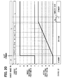
- an automatic transmission supporting, in addition to the P, R, N, and D ranges an automatic transmission supporting, in addition to the P, R, N, and D ranges, a low (L) range that is a running range realizing the non-neutral state may be adopted like, for example, a variant shown in FIG. 20 .
- L range is added, even when a re-shift command requesting switching from the L range to the N range is inputted at the actual rotational position Ma of a D-range realizable position, if an intermediate region D-L nearest to the current position Ma is, like, for example, a variant shown in FIG. 21 , considered to belong to the neutral region An, the electric motor 24 is rotated to the region D-L and then suspended.
- the target rotational position Mt may be set in the neutral region An nearest to the tentative target rotational position Mtt to comply with a re-shift command but not be set to the current actual rotational position Ms in the current actual rotational direction Da.
- the decrease in an engine torque described in relation to the first embodiment and fixing in the neutral state described in relation to the second embodiment may be implemented in combination, or one of them may be selectively implemented under a specific condition. Moreover, during fail-safe control, a warning may not be given to a user.
- the limit on the number of times that a re-shift command can be input can be set to any appropriate value other than 1. Moreover, when the presently inputted re-shift command, which exceeds the limit on the number of times that a re-shift command can be input, is rejected, warning may not necessarily be given to a user.
Abstract
Description
- The present invention relates to a shift-by-wire system. In recent years, the tendency toward a transition from a mechanical driving system to an electrical driving system has grown in the field of vehicles such as automobiles in order to cope with a demand for space saving or improvement in assembling efficiency or controllability. As an example, development of a shift-by-wire system that uses an electric motor to electrically control range switching of an automatic transmission has been under way.
- As the shift-by-wire system, a system that uses a by-wire control circuit unit to control the rotation of an electric motor conformably to a shift command inputted by a user, and thus switches ranges has been disclosed in
JP-A-2004-23890 JP-A-2004-23890 JP-A-2004-23890 - However, in the system in the
JP-A-2004-23890 - The present invention addresses the foregoing and thus it is an object to provide a shift-by-wire system that improves responsiveness to a shift command and ensures safety.
- According to various embodiments, a shift-by-wire system includes an electric motor that generates a rotational output for use in switching ranges of an automatic transmission in a vehicle and a by-wire control circuit or unit that electrically controls the rotation of the electric motor to comply with a shift command inputted by a user. When a re-shift command is inputted during switching control in which the ranges are switched by controlling the rotation of the electric motor to comply with the shift command, the by-wire control circuit, circuit, unit or the like modifies rotation control until the rotational position of the electric motor reaches a new target rotational position to comply with the re-shift command. The above described operation is performed according to the actual rotational position of the electric motor attained at the time point of input of the re-shift command.
- When a re-shift command is inputted during range switching control to comply with a shift command, rotation control may be modified based on the actual rotational position of the electric motor until the rotational position of the electric motor reaches a new target rotational position. Therefore, whatever the actual rotational position of the electric motor is at the time of input of the re-shift command, the electric motor can be rotated to the new target rotational position since the rotation control takes into account the actual rotational position. As a result, the automatic transmission will not be brought to a state contradictory to an intended shift position or operation and the responsiveness of the system to a shift command can be improved.
- Hereinafter, the rotational region of the electric motor bringing the automatic transmission to a neutral state can be defined as a neutral region. According to other embodiments, in a case where a target rotational position attained when a re-shift command is input lies in a direction opposite to the actual rotational direction of the electric motor with respect to the actual rotational position of the electric motor and the actual rotational position lies in the neutral region, the by-wire control circuit controls the rotation of the electric motor so that the rotation will be null in the neutral region to which the actual rotational position belongs. Thereafter, the by-wire control circuit rotates the electric motor in the opposite direction so that the rotational position of the electric motor will reach the target rotational position.
- Further in accordance with various embodiments, when the target rotational position lies in a direction opposite to the actual rotational direction with respect to the actual rotational position of the electric motor, the rotation of the electric motor is controlled to be null in the neutral region to which the actual rotational position belongs. The automatic transmission is thus brought to the neutral state. Therefore, the sense of discrepancy or discomposure that might be given to a user because the automatic transmission enters a non-neutral state contradictory to a user's intention can be suppressed.
- It should further be noted that reference is made herein to a non-neutral region, which can be defined as the rotational region of the electric motor bringing the automatic transmission to the non-neutral state.
- Still further in accordance with various exemplary embodiments, where the target rotational position lies in a direction opposite to the actual rotational direction of the electric motor with respect to the actual rotational position of the electric motor, the actual rotational position lies in the non-neutral region. When the neutral region lies in the actual rotational direction with respect to the actual rotational position, the by-wire control circuit continues the rotation in the actual rotational direction of the electric motor so that the rotational position of the electric motor will reach the neutral region in the actual rotational direction. The by-wire control circuit controls the rotation of the electric motor so that the rotation will be null in the neutral region. Thereafter, the by-wire control circuit rotates the electric motor in the opposite direction so that the rotational position of the electric motor will reach the target rotational position.
- When the target rotational position lies in a direction opposite to the actual rotational direction and with respect to the actual rotational position of the electric motor, the rotation of the electric motor is controlled to be null in the neutral region, which is reached by the electric motor by continuing rotation in the actual rotational direction. Thus, the automatic transmission is brought to the neutral state. As a result, the sense of discrepancy or discomposure that would be given to a user because the automatic transmission enters the non-neutral state contradictory to the user's intension can be suppressed.
- Still further in accordance with various exemplary embodiments, when at least one neutral region lies in the actual rotational direction of the electric motor with respect to the actual rotational position of the electric motor, the by-wire control circuit causes the rotational position of the electric motor to reach the neutral region closest to the actual rotational position in the actual rotational direction. Since the rotational position of the electric motor is caused to immediately reach the neutral region and the rotation thereof is nullified, the time during which the automatic transmission remains in the neutral state can be shortened as greatly as possible. Consequently, the sense of discrepancy that would be given to the user because the automatic transmission remains in the neutral state for a relatively long period of time can be avoided. Incidentally, it should be noted that when only one neutral region lies in the actual rotational direction with respect to the actual rotational position of the electric motor, that one neutral region is, for the purposes of the present disclosure, the neutral region closest to the actual rotational position as described above.
- In a case where the target rotational position lies in a direction opposite to the actual rotational direction of the electric motor with respect to the actual rotational position of the electric motor and when the actual rotational position lies in the non-neutral region and when the neutral region does not lie in the actual rotational direction with respect to the actual rotational position, the by-wire control circuit controls the rotation of the electric motor so that the rotation will be null in the non-neutral region to which the actual rotational position belongs while implementing fail-safe control for ensuring vehicle safety. Thereafter, the by-wire control circuit rotates the electric motor in the opposite direction so that the rotational position of the electric motor will reach the target rotational position.
- When the target rotational position lies in the direction opposite to the actual rotational direction with respect to the actual rotational position of the electric motor, while fail-safe control is implemented, the rotation of the electric motor is controlled to be null in the non-neutral region to which the actual rotational position belongs. Therefore, although the rotation of the electric motor is nullified in the region bringing the automatic transmission to the non-neutral state, the rotational position of the electric motor is allowed to reach the target rotational position before the rotation in the opposite direction from the actual rotational position, since vehicle safety is ensured owing to the fail-safe control, a sense of discomposure given to a user can be alleviated.
- According to various embodiments, fail-safe control is such that an engine control means for controlling the output torque of a vehicle engine decreases the output torque. Consequently, even if the rotation of the electric motor is nullified in a region that brings the automatic transmission to a non-neutral state, a sense of discomposure can be alleviated and vehicle safety can be ensured due to the decrease in the output torque of the engine.
- Fail-safe control can be further implemented in that a transmission control means, which controls the automatic transmission independently of the shift-by-wire system, fixes the automatic transmission in the neutral state. Consequently, even if the rotation of the electric motor is nullified in the region bringing the automatic transmission to the non-neutral state, a sense of discomposure can be alleviated and vehicle safety is ensured since the automatic transmission is fixed in the neutral state. In the above described scenarios, a warning unit can be included for giving warning during fail-safe control. However, since a user is informed of the fact that fail-safe control is under way, a sense of discrepancy derived from the fail-safe control itself can be alleviated.
- It should be noted that in accordance with the above description, the "non-neutral region" can be characterized as the rotational region of the electric motor realizing a range of selections involving drive engagement of the automatic transmission. Moreover, the "neutral region" can be characterized as the rotational region of the electric motor realizing the neutral range of the automatic transmission or the parking range, or may be determined and located among multiple rotational regions of the electric motor realizing multiple ranges of the automatic transmission.
- When the target rotational position lies in the actual rotational direction of the electric motor with respect to the actual rotational position of the electric motor, the by-wire control circuit continues the rotation in the actual rotational direction of the electric motor so that the rotational position of the electric motor will reach the target rotational position. Consequently, when the target rotational position lies in the actual rotational direction with respect to the actual rotational position of the electric motor, the rotation in the actual rotational direction can be continued as it is so that the rotational position of the electric motor will reach the target rotational position. Therefore, responsiveness can be improved but a sense of discrepancy or discomposure will not be given to a user.
- When a re-shift command is inputted multiple times, the by-wire control circuit rejects any additional re-shift commands that exceed an upper limit, such as a predetermined limit on the number of times a re-shift command can be inputted within a certain amount of time. Consequently, heating and break down of the by-wire control circuit that electrically controls the electric motor resulting from response to an excessive number of shift commands within a certain period of time can be suppressed. In such a case or condition, a warning unit can give warning that a re-shift command is being rejected. Since a user is informed of the rejection of the shift command, a sense of discrepancy that might occur when the automatic transmission enters a state contradictory to the intended state due to the rejection of the shift command can be alleviated.
- Other objects, features and characteristics will be appreciated and become apparent to those of ordinary skill in the art and all of which form a part of the present application. In the drawings:
-
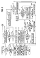
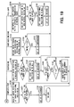
FIG. 1 is a flowchart illustrating an exemplary flow of range control in accordance with a first embodiment; -
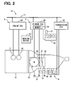
FIG. 2 is a block diagram illustrating a vehicle control system to which a shift-by-wire system in accordance with a first embodiment is adapted; -
FIG. 3 is diagram illustrating a perspective view of the detailed construction of a conversion mechanism in accordance with a first embodiment; -
FIG. 4 is a diagram illustrating a cross-sectional view along the section IV-IV of the mechanism shown inFIG. 3 ; -
FIG. 5 is a diagram illustrating a sectional view of the detailed construction of a manual valve in accordance with a first embodiment, and a working state thereof; -
FIG. 6 is a diagram illustrating a sectional view of another working state of the manual valve shown inFIG. 5 ; -
FIG. 7 is a diagram illustrating a sectional view of still another working state of the manual valve shown inFIG. 5 ; -
FIG. 8 is a diagram illustrating a sectional view of still another working state of the manual valve shown inFIG. 5 ; -
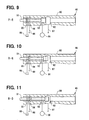
FIG. 9 is a is a diagram illustrating a sectional view of still another working state of the manual valve shown inFIG. 5 ; -
FIG. 10 is a is a diagram illustrating a sectional view of still another working state of the manual valve shown inFIG. 5 ; -
FIG. 11 is a is a diagram illustrating a sectional view of still another working state of the manual valve shown inFIG. 5 ; -
FIG. 12 is a is a flowchart illustrating an exemplary flow of range control in accordance with a first embodiment; -
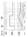
FIG. 13 is a diagram illustrating an exemplary normal operation of the shift-by-wire system in accordance with a first embodiment; -
FIG. 14 is a diagram illustrating a first exemplary re-commanded operation of the shift-by-wire system in accordance with a first embodiment; -
FIG. 15 is a diagram illustrating a second exemplary re-commanded operation of the shift-by-wire system in accordance with a first embodiment; -
FIG. 16 is a diagram illustrating a third exemplary re-commanded operation of the shift-by-wire system in accordance with a first embodiment; -
FIG. 17 is a diagram illustrating a fourth exemplary re-commanded operation of the shift-by-wire system in accordance with a first embodiment; -
FIG. 18 is a diagram illustrating a fifth exemplary re-commanded operation of the shift-by-wire system in accordance with a first embodiment; -
FIG. 19 is a flowchart illustrating an exemplary flow of a range control in accordance with a second embodiment; -
FIG. 20 is a diagram illustrating an exemplary variant of the normal operation shown inFIG. 13 ; and -
FIG. 21 is a diagram illustrating an exemplary variant of the re-commanded operation shown inFIG. 16 . - In the following description, ECU stands for electronic control unit.
Fig. 2 shows avehicle control system 10 to which a shift-by-wire system 2 in accordance with the first embodiment of the present invention is adapted. It will be appreciated that the shift-by-wire system 2 or by-wire circuit, circuit, or unit can refer to individual portions of, groups of or all of the elements associated therewith and additional elements such as elements of the shifting circuit as will be described hereinafter. Thevehicle control system 10 to be mounted in a vehicle includes the shift-by-wire system 2, an automatictransmission control system 4, and anengine control system 6. - The automatic
transmission control system 4 further includes ahydraulic circuit 44 that drives anautomatic transmission 42. Amanual valve 46 of thehydraulic circuit 44 includes a spool valve, and switches ranges of theautomatic transmission 42 with an output oil pressure depending on a spool moving position. In theautomatic transmission 42, a neutral (N) range and a parking (P) range are supported as ranges bringing the automatic transmission to a neutral state in which an output torque of aninternal combustion engine 16 in a vehicle is not transmitted to the driving wheels of the vehicle. Moreover, in theautomatic transmission 42, a reverse (R) range and a drive (D) range are supported as running ranges that bring the automatic transmission to a non-neutral state in which the output torque of theengine 16 is transmitted to the driving wheels of the vehicle. - Multiple
electromagnetic valves 48 in thehydraulic circuit 44 fasten or release associated frictional elements (not shown) of theautomatic transmission 42, whereby the shift stages of thetransmission 42 are switched. Moreover, in thehydraulic circuit 44 in the present embodiment, a predetermined frictional element is released by the associatedelectromagnetic valve 48 irrespective of the spool moving position of themanual valve 46 in order to forcibly realize the N range. Thetransmission ECU 40 is electrically connected to theelectromagnetic valves 48 and other multiple electrical elements constituting thehydraulic circuit 44, and electrically controls the actions of the electrical elements. - The shift-by-
wire system 2 further includes anactuator 21 that drives themanual valve 46 of the automatictransmission control system 4, and aconversion mechanism 22. In theactuator 21, anelectric motor 24 includes a switched reluctance motor that generates a rotational output when in the conducting or energized state. Adeceleration mechanism 25 includes a gear mechanism that decelerates a rotational output of themotor 24, and transmits the rotational output to theconversion mechanism 22, which converts the rotational output into a linear motion. Accordingly, the spool moving position of themanual valve 46 is switched from one position to another. Consequently, in the present embodiment, the ranges of theautomatic transmission 42 are switched based on the rotational position of theelectric motor 24, which, hereinafter, is referred to simply as the motor rotational position. - The by-
wire ECU 20 is electrically connected to each of theelectric motor 24, arotational position sensor 26, and aselector sensor 28. Therotational position sensor 26 includes, for example, a rotary encoder, and is disposed on the output side of theelectric motor 24 in order to detect the motor rotational position. Moreover, theselector sensor 28 detects a user-requested range according to a manipulation performed on arange selector 12 of the vehicle, and outputs an analog signal or a digital signal representing the detected range. Consequently, the by-wire ECU 20 stores necessary information in amemory 29, and electrically controls the rotation of theelectric motor 24 on the basis of the results of detections by thesensors selector sensor 28 changes from one to another, that is, when a range change is requested, the by-wire ECU 20 in the present embodiment decides that a shift command has been inputted. The by-wire ECU 20 implements rotation control in theelectric motor 24 to switch the ranges so that the actual motor rotational position detected by therotational position sensor 26 will be brought to a target rotational position, which is a rotational position of the motor associated with the changed requested range. - The by-
wire ECU 20 is also electrically connected to awarning device 19 of the vehicle, and, if necessary, controls thewarning device 19 so as to give a predetermined warning. Warning may be produced by displaying a warning lamp in, for example, the dashboard of the vehicle or by displaying a screen image on the monitor of the vehicle, by outputting a sound from a loudspeaker of the vehicle, or the like. - The
engine ECU 60 of theengine control system 6 is electrically connected to athrottle device 17 and afuel injection valve 18 which are included in theengine 16 of the vehicle. Thethrottle device 17 adjusts a throttle angle in an air intake passage in theengine 16. Moreover, thefuel injection valve 18 adjusts an injection quantity to be fed to an intake pipe or a cylinder in theengine 16. Consequently, when theengine ECU 60 electrically controls thethrottle device 17 andfuel injection valve 18, the rotating speed and the output torque of theengine 16 are adjusted. - As previously described, a rotational output of the
motor 24, is converted into a linear motion by theconversion mechanism 22, which, as shown inFIG. 3 , includes adetent plate 80, adetent spring 81, apark rod 82, apark pole 83, and apark gear 84. Thedrive shaft 86 of thedetent plate 80 is disposed to be freely rotatable, and fixed to theoutput shaft 27 of thedeceleration mechanism 25. Aspool 91 of themanual valve 46 is linked to thedetent plate 80. Consequently, in the present embodiment, when thedetent plate 80 is rotated along with the rotation of theelectric motor 24 linked to thedetent plate 80 via thedeceleration mechanism 25, thespool 91 moves in axial directions. Consequently, the ranges of theautomatic transmission 42 are switched. - As shown in
FIG. 4 , fourindentations detent plate 80 in the rotation direction thereof. Theindentations automatic transmission 42. Thedetent spring 81 is disposed to engage with any of theindentations detent plate 80. Consequently, when the rotational position of thedetent plate 80 allows thedetent spring 81 to engage with theP indentation 80a, the P range is realized. Likewise, when the rotational positions of thedetent plate 80 allow thedetent spring 81 to engage with theR indentation 80b,N indentation 80c, andD indentation 80d respectively, the R range, N range, and D range are realized, respectively. When the P range is activated or deactivated, an additional locking or unlocking operation can occur. - For example, as also shown in
FIG. 3 , thepark rod 82 is fixed to thedetent plate 80. Aconical member 88 attached to thepark rod 82 abuts on thepark pole 83. Thepark pole 83 is able to freely pivot and mesh with thepark gear 84. Thepark gear 84 is fixed to the output shaft (not shown) of theautomatic transmission 42. By thepark pole 83 meshing with or receding from thepark gear 84 according to the pivot position thereof, the park gear is locked or unlocked. - To be more specific, when the
detent plate 80 rotates to a P-range realizable position, thepark rod 82 moves to thepark pole 83, and theconical member 88 causes thepark pole 83 to mesh with thepark gear 84. Thegear 84 is thereby locked. Conversely, when thedetent plate 80 rotates to an R-range realizable position beyond the P-range realizable position, thepark rod 82 moves to a side opposite to thepark pole 83. Theconical member 88 causes thepark pole 83 to recede from thepark gear 84. Thegear 84 is therefore unlocked. - As previously described,
manual valve 46 switches ranges of theautomatic transmission 42 with an output oil pressure depending on a spool moving position, and, as shown inFIG. 5 , further includes avalve body 90 and aspool 91. In the peripheral wall of thevalve body 90 having a cylindrical shape, a D-range pressure port 92, aline pressure port 93, an R-range pressure port 94, and adrain pressure port 95 are formed, in that order, from one end thereof to the other end thereof. Theline pressure port 93 communicates with a linepressure generation source 96 such as a hydraulic pump that generates a line pressure. The D-range pressure port 92 communicates with anoil path 97 that can feed an oil pressure to the frictional elements which are fastened in the D range in thehydraulic circuit 44 of theautomatic transmission 42. The R-range pressure port 94 communicates with anoil path 98 that can feed an oil pressure to the frictional elements which are fastened in the R range in thehydraulic circuit 44. Thedrain pressure port 95 communicates with anoil pan 99 serving as a drain that opens to the air. Incidentally, though not shown, in the present embodiment, the end of thevalve body 90 near the D-range pressure port 92 also communicates with theoil pan 99. - The
valve body 90 bears thespool 91 on the peripheral wall thereof so that thespool 91 can freely reciprocate in axial directions. Theports spool 91, whereby the ranges of theautomatic transmission 42 are switched. - Specifically, when the
spool 91 moves to the position shown inFIG. 5 or an area around the position, theline pressure port 93 does not communicate with theother ports oil paths range pressure ports park gear 84 of theconversion mechanism 22 is locked, the P range is realized. - When the
spool 91 moves to the position shown inFIG. 6 or an area around the position, a line pressure from linepressure generation source 96 is fed through theline pressure port 93, through the R-range pressure port 94, and to theoil path 98. Consequently, the R range is realized. - When the
spool 91 moves to the position shown inFIG. 7 or an area around the position, since theline pressure port 93 does not communicate with theother ports oil paths range pressure ports park gear 84 is unlocked, the N range is realized. - When the
spool 91 moves to the position shown inFIG. 8 or an area around the position, a line pressure from linepressure generation source 96 is fed through theline pressure port 93, through the D-range pressure port 92, and to theoil path 97. Consequently, the D range is realized. - As shown in
FIG. 9 to FIG. 11 , when thespool 91 moves to any of intermediate areas P-R, R-N, and N-D that are positioned among areas realizing the defined ranges, since theline pressure port 93 does not communicate with theother ports oil paths range pressure ports park gear 84 is unlocked, theautomatic transmission 42 enters a state that is equivalent to the neutral state in which the N range is realized. - Next, a range control flow to be implemented by the by-
wire ECU 20 will be described below with reference toFIG. 1 andFIG. 12 . The range control flow is initiated with the ignition switch of the vehicle turned on, is repeated at intervals of a predetermined cycle, and is terminated with the ignition switch turned off. - As described in
FIG. 1 , at S10 of the exemplary range control procedural flow, a current status (ST) is checked. The status ST falls into six states of Standby, Driving, Complete Stop, Suspension, Continued Driving, and Fail-safe. - If the status ST is recognized as Standby at S10, processing proceeds to S100 of standby processing. At S100, a decision is made based on a range detected by the
selector sensor 28 whether a shift command is inputted in a standby state. - If a shift command is inputted, corresponding to YES at S100, processing proceeds to S101, where a re-command flag F stored in the
memory 29 is reset to off. At S102, a range a user has requested using the shift command, that is the range currently detected, for example, by theselector sensor 28, is designated as a target range Rt, and stored in thememory 29. At S103, a motor rotational position realizing the target range Rt designated at S102 is designated as a target rotational position Mt, and stored in thememory 29. For example, if the D range is requested in a state in which the electric motor currently lies at the P-range position, the target range Rt is set to the D range. The target rotational position Mt is therefore set to, for example, 600° that is the motor rotational position equivalent to the D range. The set position is stored in thememory 29. Thereafter, at S104, the status ST is changed to Driving. Range switching control is initiated for rotating theelectric motor 24 and processing returns to S10. - If a shift command is not inputted, corresponding to NO at S100, procedures S101 to S104 are skipped, and processing returns to S10. In the standby state, the
electric motor 24 is stopped until a shift command is inputted, and the range of theautomatic transmission 42 is maintained. - If the status ST is recognized as Driving at S10, processing proceeds to S110 of driving processing where the
electric motor 24 is rotated to the target rotational position Mt stored in thememory 29 from a previous period in the above described standby position or from an initialization procedure or the like as will be appreciated. - At S111, a decision is made based on a range currently detected by the
selector sensor 28 whether a re-shift command, which is a shift command other than the previous shift command, has been presently inputted during range switching control. - If a re-shift command is not inputted during range switching control, corresponding to a NO at S111, processing proceeds to S112, where the actual rotational position Ms of the
electric motor 24 currently detected by therotational position sensor 26 is compared with the target rotational position Mt stored in thememory 29. A decision is made regarding whether a difference between the positions Ma and Mt falls below a reference value Δs. - It should be noted that the reference value Δs is set to a value smaller than the range of rotational regions of the
electric motor 24 associated with the spool moving positions or areas around the positions, which are shown inFIG. 5 to FIG. 8 and at or in which themanual valve 46 realizes the ranges. Consequently, when the actual rotational position Ma associated with the current actual range Ra has approached the target rotational position Mt at a distance of the reference value Δs or smaller, the actual rotational position Ma has reached the target rotational position Mt with an error between them. - If the actual rotational position Ma has substantially reached the target rotational position Mt, corresponding to YES at S112, processing proceeds to S113, where the status ST is changed to Complete Stop, and processing returns to S10. If the actual rotational position Ma has not reached the target rotational position Mt, corresponding to NO at S112, S113 is skipped and processing returns to S10. Consequently, in such a position, the status ST is held in Driving and processing returns to S10, where subsequent processing is executed. The rotation of the
electric motor 24 heading for the target rotational position Mt is continued. - It should be noted that the above-described processing is based on a NO determination at S111. If a re-shift command is inputted during range switching control, corresponding to YES at S111, processing proceeds to S114, where a decision is made regarding whether the re-command flag F stored in the
memory 29 is set or "no." If the re-command flag F is not set, which can be referred to as reset, "off," or the like, corresponding to NO at S114, processing proceeds to S115, and the re-command flag F stored in thememory 29 is set. Namely, in the present embodiment, if the re-shift command is inputted even once during range switching control, the re-command flag F will be set. - At S116, a range requested with the re-shift command, that is, a range currently detected by the
selector sensor 28, is re-designated as a new target range Rt and stored in thememory 29 in place of any previously stored value. At S117, a motor rotational position realizing the new target range Rt designated at S116 is designated as a tentative target rotational position Mtt, that is, the tentative new position of the target rotational position Mt, and stored in thememory 29. Thereafter, at S118, a decision is made regarding whether the tentative target rotational position Mtt designated at S117 exists in the current actual rotational direction Da of theelectric motor 24. - If the tentative target rotational position Mtt lies in the actual rotational direction Da, corresponding to YES at S118, processing proceeds to S119, where the target rotational position Mt stored in the
memory 29 is updated with the tentative target rotational position Mtt and processing returns to S10. The status ST is held in Driving and processing returns to S10, where driving processing at S110 is executed. The rotation in the actual rotational direction Da of theelectric motor 24 is continued toward the target rotational position Mt updated at S119. - If the tentative target rotational position Mtt exists in a direction Dr opposite to the actual rotational direction Da, corresponding to NO at S118, processing proceeds to S120, where a decision is made regarding whether the present actual rotational position Ma of the
electric motor 24, as detected, for example, by therotational position sensor 26, exists in a neutral region An. The neutral region An can refer to the rotational region of theelectric motor 24 that brings theautomatic transmission 42 to a neutral state as can occur in accordance with thespool 91 of themanual valve 46 moving to: the area realizing the N range as shown inFIG. 7 ; the area realizing the P range as shown inFIG. 5 ; and any of the intermediate areas P-R, R-N, and N-D spaced among the areas realizing the P, R, N, and D ranges as shown inFIG. 9 to FIG. 11 . - If the current actual rotational position Ma lies in the neutral region An, corresponding to YES at S120, processing proceeds to S121. The status ST is changed to Suspension, and processing returns to S10. If the current actual rotational position Ma lies in a non-neutral region Ad, corresponding to NO at S120, processing proceeds to S122. A decision is made regarding whether at least one neutral region An exists in the current actual rotational direction Da. The non-neutral region Ad can refer to the rotational region of the
electric motor 24 bringing theautomatic transmission 42 to a non-neutral state by inducing thespool 91 of themanual valve 46 to move to: the area realizing the R range as shown inFIG. 6 ; the area realizing the D range as shown inFIG. 8 ; and the area realizing the D range as shown inFIG. 8 . - If at least one neutral region An exists in the actual rotational direction Da, corresponding to YES at S122, processing proceeds to S123, where the target rotational position Mt is set in the neutral region An closest to the actual rotational position Ma in the current actual rotational direction Da. The target rotational position Mt stored in the
memory 29 is updated. At S124, after the status ST is changed to Continued Driving, processing returns to S10. In contrast, if any neutral region An does not exist in the actual rotational direction Da, corresponding to NO at S122, processing proceeds to S125. The status ST is changed to Fail-safe, and processing returns to S10. - A above description is based on a NO at S114. If the re-command flag F stored in the
memory 29 is set to on, corresponding to YES at S114, processing proceeds to S126. There, since the number of times a re-shift command is inputted during range switching control is two or more, a control signal is given to thewarning device 19 in order to warn a user that the re-shift command should be rejected. Thereafter, when processing proceeds to S112, if the re-shift command is inputted for the second time or more, the target range Rt is not updated but a decision is made regarding whether range switching should be completed. Consequently, in the present embodiment, a limiting number of times of input of the re-shift command is set to one, and any re-shift command that inputted a second or greater time, which exceeds the limiting number of times, is rejected. - If the status ST is recognized as Complete Stop at S10, processing proceeds to S130 of complete stop processing as described in
FIG. 12 . At S130, the rotation of theelectric motor 24 is controlled to be null at the target rotational position Mt, and theelectric motor 24 is thus stopped. - At S131, a decision is made regarding whether a designated time Ks or a greater amount of time has elapsed since the
electric motor 24 was stopped at S130, which is immediately after the status ST is changed to Complete Stop nearest to S113 of driving processing, such as, for example, occurring in the immediately preceding control routine. It will be understood that reference hereinafter to "nearest to" a given routine will also refer to processing in the immediately preceding routine. - If a designated time Ks or a greater amount of time has elapsed since the
electric motor 24 was stopped, corresponding to YES at S131, theelectric motor 24 is considered to be completely stopped and processing then proceeds to S132. At S132, the status ST is changed to Standby, and range switching control is terminated. Processing then returns to S10. If a designated time Ks or a greater amount of time has not elapsed since theelectric motor 24 was stopped, corresponding to NO at S131, S132 is skipped and processing returns to S10. Consequently, range switching control is continued until theelectric motor 24 is completely stopped. - If the status ST is recognized as Suspension at S10, processing proceeds to S140 of suspension processing. At S140, the rotation of the
electric motor 24 is controlled to be null in the neutral region An in order to stop themotor 24. Consequently, vehicle safety is ensured. - At S141, a decision is made regarding whether a designated time Kh or a greater amount of time has elapsed since the
electric motor 24 was stopped at S140, which is immediately after the status ST is changed to Suspension nearest to S121 of driving processing or nearest to S152 of continued driving processing, which will be described greater detail hereinafter. - If a designated time Kh or a greater amount of time has elapsed since the
electric motor 24 was stopped, corresponding to YES at S141, the reversion of theelectric motor 24, which is a switched reluctance motor, is considered to be enabled, and processing proceeds to S142. At S142, the target rotational position Mt stored in thememory 29 is updated with the tentative target rotational position Mtt stored in thememory 29, that is, the tentative target rotational position Mtt designated at the nearest S117 of driving processing. At S143, the status ST is changed to Driving. - Thereafter, if it is confirmed that a re-shift command has been executed, corresponding to YES at S144 and flag F is set, corresponding to YES at S145, warning that a re-shift command is rejected is given at S146, and processing returns to S10. In contrast, if a re-shift command has not been executed, or if the flag F is not set, corresponding to NO at any one of S144 and S145, S146 is skipped and processing returns to S10.
- As mentioned above, after the
electric motor 24 is suspended for the designated time Kh, processing returns to S10, and S110 of driving processing is executed. Consequently, theelectric motor 24 is rotated toward the target rotational position Mt updated atS 142. - If a designated time Kh or a greater amount of time has not elapsed since the
electric motor 24 was stopped, corresponding to NO at S141, steps S142 and S143 are skipped and processing returns toS 10 through steps S 144 to S146. - If the status ST is recognized as Continued Driving at S10, processing proceeds to S150 of continued driving processing. At S150, the rotation in the actual rotational direction Da of the
electric motor 24 is continued toward the target rotational position Mt stored in thememory 29, that is, the target rotational position Mt designated in the neutral region An at the nearest S123 of driving processing. - If a difference between the current actual rotational position Ma and the target rotational position Mt in the neutral region An falls below the reference value Δs, corresponding to YES at S151, the actual rotational position Ma is considered to have substantially reached the target rotational position Mt in the neutral region An, and processing proceeds to S152. The status ST is then changed to Suspension. Thereafter, processing returns to S10 through steps S144 to S146 in the same manner as that during suspension processing. After the
electric motor 24 is rotated from the non-neutral region Ad to the neutral region An, processing returns to S10, and S140 of suspension processing is executed. Consequently, theelectric motor 24 is stopped in the neutral region An, and vehicle safety is ensured. - If a difference between the current actual rotational position Ma and the target rotational position Mt in the neutral region An does not fall below the reference value Δs, corresponding to NO at S151, the current actual rotational position Ma is considered to still lie in the non-neutral region Ad, and S152 is skipped. Thereafter, processing returns to S10 through steps S144 to S146 in the same manner as that during suspension processing.
- If the status ST is recognized as Fail-safe at S10, processing proceeds to S160 where fail-safe control is implemented through fail-safe processing. Specifically, in the present embodiment, a control signal causing at least one of the throttle angle of the
throttle device 17 and the injection quantity of thefuel injection valve 18 to be decreased is given to theengine ECU 60, whereby an engine torque is decreased until the engine speed equals an idle speed, or the like. - In the present embodiment, once fail-safe control is initiated at S160, which can occur immediately after the status ST is changed to Fail-safe during the nearest procedure S125 of driving processing, the fail-safe control is continued until the rotation of the
electric motor 24 is initiated at S110 of driving processing as described in greater detail hereinafter. In the present embodiment, when the fail-safe control is continued, a control signal is given to thewarning device 19 and a user is warned of the continuation of fail-safe control. - At 161, the rotation of the
electric motor 24 is controlled to be null in the non-neutral region Ad in order to stop themotor 24. In such as position, since fail-safe control initiated at S160 is continued, even if theautomatic transmission 42 enters the non-neutral state because theelectric motor 24 is stopped in the non-neutral region Ad, vehicle safety is ensured. - At S162, after vehicle safety is ensured in the manner mentioned above, if the designated time Kh or a greater amount of time has elapsed since the
electric motor 24 is stopped at S161 immediately after the status ST is changed to Fail-safe at the nearest S125 of driving processing, corresponding to YES at S162, the reversion of theelectric motor 24 is considered to be enabled, and processing proceeds to S163. The target rotational position Mt currently stored in thememory 29 is updated with the tentative target rotational position Mtt, which is also stored in thememory 29. That is, the tentative target rotational position Mtt designated at the nearest S117 of driving processing is determined to be the target position. At S164, the status ST is changed to Driving. Thereafter, processing returns to S10 through steps S144 to S146 as previously described. After theelectric motor 24 is suspended for the designated time Kh, processing returns to S10, and S110 of driving processing is executed. Consequently, theelectric motor 24 is rotated toward the target rotational position Mt updated at S163. - If the designated time Kh or a greater amount of time has not elapsed since the
electric motor 24 is stopped, corresponding to NO at S162, steps S163 and S164 are skipped. Thereafter, processing returns to S10 through steps S144 to S146. - Characteristic operations of the shift-by-
wire system 2, as shown for example, inFIG. 13 , realized according to the foregoing range control flow, will now be described with reference to an example of normal operation performed in a case where a re-shift command is not inputted during range switching control initiated with input of a shift command. In the example shown inFIG. 13 , switching from the P range to the D range can be requested with the shift command. - First, if a shift command is inputted with the status ST set to Standby, the target range Rt is set to the D range, and the target rotational position Mt of the
electric motor 24 is set to a D-range realizable position. Thereafter, the status ST is changed to Driving, and theelectric motor 24 is rotated toward the target rotational position Mt. - When the actual rotational position Ma of the
electric motor 24 reaches the target rotational position Mt, the status ST is changed to Complete Stop, and theelectric motor 24 is stopped. After the designated time Ks elapses, when the status ST is changed to Standby, range switching control is terminated. -
FIG. 14 through FIG. 18 show first through fifth exemplary re-commanded operations to be performed in a case where a re-shift command is inputted during range switching control initiated with input of a shift command. - A first exemplary operation, shown in
FIG. 14 , is concerned with a case where the target rotational position Mt necessary to comply with a re-shift command exists in the actual rotational direction Da with respect to the actual rotational position Ma of theelectric motor 24 when the re-shift command is input. In the first exemplary operation as shown inFIG. 14 , switching from the P range to the N range can be requested with the first shift command, and switching from the N range to the D range can be requested with the re-shift command. - First, a shift command is inputted with the status ST set to Standby. After the target range Rt is set to the N range and the target rotational position Mt is set to an N-range realizable position, the status ST is changed to Driving, and the
electric motor 24 is rotated toward the target rotational position Mt. - Thereafter, if a re-shift command is inputted prior to realization of the N range, a new target rotational position Mt to be set to a D-range realizable position to comply with the command (which corresponds to the tentative target rotational position Mtt in the aforesaid control flow) exists in the actual rotational direction Da attained at the time point of input of the command. In the present embodiment, the rotation in the actual rotational direction Da is continued toward the new target rotational position Mt to comply with the re-shift command.
- As mentioned above, when the actual rotational position Ma reaches the new target rotational position Mt, the status ST is changed to Complete Stop. The
electric motor 24 is therefore stopped. After the time Ks elapses, when the status ST is changed to Standby, range switching control is terminated. - In the case where the target rotational position Mt to comply with a re-shift command exists in the actual rotational direction Da, the rotation in the actual rotational direction Da is continued as it is. Thus, responsiveness can be improved while suppressing a sense of discrepancy or discomposure from being given to a user.
- A second exemplary operation shown, for example, in
FIG. 15 , is concerned with a case where the target rotational position Mt required to comply with a re-shift command exists in a direction Dr opposite to the actual rotational direction attained at the time point of input of the re-shift command with respect to the actual rotational position Ma lying in the neutral region An at the time point of input of the re-shift command. In the exemplary second operation inFIG. 15 , switching from the P range to the D range can be requested with the first shift command, and switching from the D range to the R range can be requested with a re-shift command at an N-range realizable position belonging to the neutral region An. - First, a shift command is inputted with the status ST set to Standby. After the target range Rt is set to the D range and the target rotational position Mt is set to a D-range realizable position, the status ST is changed to Driving, and the
electric motor 24 is rotated toward the target rotational position Mt. - Thereafter, when a re-shift command is inputted prior to realization of the D range at the actual rotational position Ma, which realizes the N range, a new target rotational position Mt is set to an R-range realizable position required to comply with the command. The new target rotational position Mt corresponds to the tentative target rotational position Mtt and exists in the direction Dr opposite to the actual rotational direction Da attained at the time point of input of the command. In the present embodiment, the status ST is changed to Suspension, and the rotation of the
electric motor 24 is controlled to be null at the actual rotational position Ma that realizes the N range. After the designated time Kh elapses, if the status ST is changed to Driving, theelectric motor 24 is rotated toward the new target rotational position Mt to comply with the re-shift command. - As mentioned above, when the actual rotational position Ma reaches the new target rotational position Mt, the status ST is changed to Complete Stop. The
electric motor 24 is therefore stopped. After the time Ks elapses, if the status ST is changed to Standby, range switching control is terminated. - If the target rotational position Mt, required to comply with a re-shift command, exists in the direction Dr opposite to the actual rotational direction Da, the
electric motor 24 is immediately stopped in the neutral region An before being reversed to the direction Dr. Consequently, an event that a sense of discrepancy or discomposure is given to a user can be suppressed. - In a third exemplary operation, as shown in
FIG. 16 , the target rotational position Mt required to comply with a re-shift command exists in the direction Dr opposite to the actual rotational direction Da attained at the time point of input of the re-shift command with respect to the actual rotational position Ma lying in the non-neural region Ad at the time point of input of the re-shift command. Further, at least one neutral region An exists in the actual rotational direction Da. In the example ofFIG. 16 , switching from the P range to the D range can be requested with the first shift command, and switching from the D range to the P range can be requested with a re-shift command inputted at an R-range realizable position belonging to the non-neutral region Ad. - First, a shift command is inputted with the status ST set to Standby. After the target range Rt is set to the D range and the target rotational position Mt is set to a D-range realizable position, the status ST is changed to Driving. The
electric motor 24 is therefore rotated toward the target rotational position Mt. - Thereafter, if a re-shift command is inputted at the actual rotational position Ma, which realizes the R range, prior to realization of the D range, a new target rotational position Mt set to a P-range realizable position to comply with the command and corresponding to the tentative target rotational position Mtt, exists in the direction Dr opposite to the actual rotational direction Da attained at the time point of input of the command. Moreover, at this time, two intermediate regions R-N and N-D belonging to the neutral region An exist in the actual rotational direction Da. Therefore, in the present embodiment, the status ST is changed to Continued Driving. The rotation in the actual rotational direction Da is therefore continued toward the intermediate region R-N closest to the current actual rotational position Ma.
- As a result, when the actual rotational position Ma reaches the intermediate region R-N, the status ST is changed to Suspension. The rotation of the
electric motor 24 is therefore controlled to be null in the intermediate region R-N. After the designated time Kh elapses, if the status ST is changed to Driving, theelectric motor 24 is rotated toward the new target rotational position Mt to comply with the re-shift command. - As mentioned above, when the actual rotational position Ma reaches the new target rotational position Mt, the status ST is changed to Complete Stop. The
electric motor 24 is therefore stopped. After the time Ks elapses, when the status ST is changed to Standby, range switching control is terminated. - In the case where the target rotational position Mt to comply with a re-shift command exists in the direction Dr opposite to the actual rotational direction Da, the
electric motor 24 is rotated to the neutral region An before being reversed in the direction Dr, and then stopped. Consequently, an event that a sense of discrepancy or discomposure is given to a user can be suppressed. Moreover, in the present embodiment, theelectric motor 24 is rotated to the neutral region An closest to the actual rotational position Ma, and stopped for a time duration required for reversion. Consequently, the time during which theautomatic transmission 42 enters the neutral state can be shortened, and a sense of discrepancy can be alleviated. - In a fourth exemplary operation, as shown in
FIG. 17 , the target rotational position Mt required to comply with a re-shift command exists in the direction Dr opposite to the actual rotational direction Da attained at the time point of input of the re-shift command with respect to the actual rotational position Ma lying in the non-neutral region Ad at the time point of input of the re-shift command. The neutral region An does not exist in the actual rotational direction Da. In the present example, switching from the P range to the D range can be requested with the first shift command, and switching from the D range to the N range can be requested with the re-shift command inputted at a D-range realizable position belonging to the non-neutral region Ad. - First, a shift command is inputted with the status ST set to Standby. After the target range Rt is set to the D range and the target rotational position Mt is set to a D-range realizable position, the status ST is changed to Driving. The
electric motor 24 is therefore rotated toward the target rotational position Mt. - Thereafter, if a re-shift command is inputted at the actual rotational position that realizes the D range, before the status ST is changed to Standby, a new target rotational position Mt is set to an N-range realizable position to comply with the command and corresponds to the tentative target rotational position Mtt. The new target rotational position Mt exists in the direction Dr opposite to the actual rotational direction Da attained at the time point of input of the command. Moreover, no neutral regions An exist in the actual rotational direction Da. In the present embodiment, the status ST is changed to Fail-safe, while an engine torque is decreased to effect fail-safe control and a warning of the decrease is provided, the rotation of the
electric motor 24 is controlled to be null at the actual rotational position Ma realizing the D range. After the designated time Kh elapses, if the status ST is changed to Driving, theelectric motor 24 is rotated toward the new target rotational position Mt to comply with the re-shift command. - As mentioned above, when the actual rotational position Ma reaches the new target rotational position Mt, the status ST is changed to Complete Stop. The
electric motor 24 is therefore stopped. After the time Ks elapses, if the status ST is changed to Standby, range switching control is terminated. - Where the target rotational position Mt required to comply with a re-shift command exists in the direction Dr opposite to the actual rotational direction Da, while fail-safe control intended to ensure safety is implemented, the
electric motor 24 is stopped in the non-neutral region Ad before being reversed in the direction Dr. Thus, a user's sense of discomposure can be alleviated. - In a fifth exemplary operation, shown in
FIG. 18 , while theelectric motor 24 is rotated toward the target rotational position Mt to comply with a re-shift command, the re-shift command is inputted for a second time, which exceeds a limit that is placed on the number of times for shifting. Switching from the D range to the N range can be requested with the second-time re-shift command. When theelectric motor 24 has been rotated to comply with a first-time re-shift command, and a second-time re-shift command is inputted, the second-time re-shift command is rejected and a user is warned of the rejection. Consequently, while a sense of discrepancy derived from the rejection of the re-shift command is alleviated, a D-range realizable position to comply with the first-time re-shift command is regarded as the target rotational position Mt so that the actual rotational position Ma will reach the target rotational position Mt. After the actual rotational position Ma reaches the target rotational position Mt, the status ST is changed to Complete Stop. After theelectric motor 24 is stopped, if the status ST is changed to Standby, range switching control is terminated. - Since an inputted re-shift command that exceeds a limit for the number of times a re-shift command can be entered is rejected, the likelihood that the by-
wire ECU 20 is overheated and eventually damaged because of the input of the repeating of the shift command due to mischief or the like, can be reduced. - As described, according to the first embodiment, responsiveness can be improved by handling a re-shift command during range switching control. Moreover, safety can be ensured by suppressing shifting related events that give a sense of discrepancy or discomposure to a user.
- Incidentally, in accordance with a first embodiment, the
warning device 19, the by-wire ECU 20, thetransmission ECU 40 andhydraulic circuit 44, theengine ECU 60 are all variously set forth in accordance with various means recited in the claims. - As described in
FIG. 19 , a second embodiment is described herein that is a variant of the first embodiment. In the second embodiment, at S200 of fail-safe processing that proceeds when the status ST is recognized as Fail-safe, theautomatic transmission 42 is fixed in the neutral state based on the fail-safe control and independent of the fail-safe control to be implemented in theelectric motor 24 lying in the non-neutral region Ad. - To be more specific, a control signal causing a predetermined
electromagnetic valve 48 to release the associated frictional element so as to forcibly realize the N range is fed to thetransmission ECU 40. Consequently, theautomatic transmission 42 is fixed in the neutral state and vehicle safety is ensured. Therefore, even if theelectric motor 24 is stopped in the non-neutral region Ad at S161 succeeding S200, a sense of discomposure to be given to a user can be alleviated. - Multiple embodiments have been described herein. However, the present invention should not be interpreted as being restricted to the embodiments, but can be applied to various embodiments without a departure from the invention.
- Specifically, the
electric motor 24 may include any type of motor other than the switched reluctance motor. The time Kh during which the rotation of theelectric motor 24 is controlled to be null by performing suspension processing and fail-safe processing should be appropriately designated based on the type ofelectric motor 24 employed. For example, the time may be designated so that the rotation of theelectric motor 24 can be instantaneously nullified and then reversed. - The by-wire control circuit may be formed with one electric circuit or multiple electric circuits. The electric circuit forming the by-wire control circuit can include the
ECU other system - The actual rotational position Ma may be indirectly calculated based on the result of detection by an inhibiter switch, a linear sensor, or any other range sensor that detects an actual range Ra on the basis of, for example, the input-side rotational position or output-side driving position of the
conversion mechanism 22 or the spool moving position of themanual valve 46, and used for control. - As the
automatic transmission 42, aside from an automatic transmission supporting four ranges of the P, R, N, and D ranges, an automatic transmission supporting, in addition to the P, R, N, and D ranges, a low (L) range that is a running range realizing the non-neutral state may be adopted like, for example, a variant shown inFIG. 20 . Moreover, in the case where the L range is added, even when a re-shift command requesting switching from the L range to the N range is inputted at the actual rotational position Ma of a D-range realizable position, if an intermediate region D-L nearest to the current position Ma is, like, for example, a variant shown inFIG. 21 , considered to belong to the neutral region An, theelectric motor 24 is rotated to the region D-L and then suspended. - At S123 of driving processing, the target rotational position Mt may be set in the neutral region An nearest to the tentative target rotational position Mtt to comply with a re-shift command but not be set to the current actual rotational position Ms in the current actual rotational direction Da.
- As for fail-safe control, the decrease in an engine torque described in relation to the first embodiment and fixing in the neutral state described in relation to the second embodiment may be implemented in combination, or one of them may be selectively implemented under a specific condition. Moreover, during fail-safe control, a warning may not be given to a user.
- Further, it will be appreciated that the limit on the number of times that a re-shift command can be input can be set to any appropriate value other than 1. Moreover, when the presently inputted re-shift command, which exceeds the limit on the number of times that a re-shift command can be input, is rejected, warning may not necessarily be given to a user.
Claims (20)
- A shift-by-wire system comprising:an electric motor (24) that generates a rotational output to be used to switch a range of an automatic transmission (16) in a vehicle; anda by-wire control circuit (2, 20) that electrically controls the rotation of the electric motor to a target rotational position (Mt) to comply with an inputted shift command,wherein:when a re-shift command is inputted during a rotation control operation that switches the range, the rotation control operation applied to the electric motor so as to generate the rotational output to comply with the inputted shift command according to the actual rotational position (Ma) of the electric motor attained when the re-shift command is inputted, the by-wire control unit modifies the rotation control operation until the rotational position of the electric motor reaches a new target rotational position (Mtt) to comply with the re-shift command.
- The shift-by-wire system according to claim 1, wherein:when the new target rotational position lies in a direction opposite to the actual rotational direction (Da) of the electric motor at the time of the input of the re-shift command with respect to the actual rotational position;when the actual rotational position lies in a neutral region that includes a rotational region of the electric motor that brings the automatic transmission to a neutral state (N, P); andafter the by-wire control drcuit controls the rotation of the electric motor so that the rotation of the electric motor will be null in the neutral region to which the actual rotational position belongs,the by-wire control drcuit rotates the electric motor in the opposite direction so that the rotational position of the electric motor will reach the new target rotational position.
- The shift-by-wire system according to claim 1 or claim 2, wherein:when the new target rotational position lies in a direction opposite to the actual rotational direction of the electric motor at the time of the input of the re-shift command with respect to the actual rotational position;when the actual rotational position lies in a non-neutral region that includes a rotational region of the electric motor that brings the automatic transmission to a non-neutral state (D, R) and the neutral region lies in the actual rotational direction with respect to the actual rotational position; andafter the by-wire control circuit continues the rotation in the actual rotational direction of the electric motor so that the rotational position of the electric motor will reach the neutral region in the actual rotational direction, and controls the rotation of the electric motor so that the rotation of the electric motor will be null in the neutral region,the by-wire control circuit rotates the electric motor in the opposite direction so that the rotational position of the electric motor will reach the new target rotational position.
- The shift-by-wire system according to claim 3, wherein:when at least one neutral region lies in the actual rotational direction with respect to the actual rotational position, the by-wire control circuit causes the rotational position of the electric motor to reach the neutral region nearest the actual rotational position in the actual rotational direction.
- The shift-by-wire system according to any of claims 1 to 4, wherein:when the new target rotational position lies in a direction opposite to the actual rotational direction of the electric motor attained at the time point of input of the re-shift command with respect to the actual rotational positionwhen the actual rotational position lies in a non-neutral region that includes a rotational region of the electric motor that brings the automatic transmission to a non-neutral state; and the neutral region does not lie in the actual rotational direction with respect to the actual rotational position; andafter the by-wire control circuit controls the rotation of the electric motor so that the rotation of the electric motor will be null in the non-neutral region, to which the actual rotational position belongs, while implementing fail-safe (ST=FAIL-SAFE) control for ensuring vehicle safety,the by-wire control circuit rotates the electric motor in the opposite direction so that the rotational position of the electric motor will reach the new target rotational position.
- The shift-by-wire system according to claim 5, further comprising an engine control means (6, 60) for controlling an engine of the vehicle, wherein the fail-safe control includes decreasing an output torque of the engine by the engine control means.
- The shift-by-wire system according to claim 5 or claim 6, further comprising a transmission control means (4, 40) for controlling the automatic transmission independently of the shift-by-wire system, wherein the fail-safe control includes fixing the automatic transmission in the neutral state by the transmission control means.
- The shift-by-wire system according to any of claims 5 to 7, further comprising a warning unit (19) that gives warning during the fail-safe control.
- The shift-by-wire system according to any of claims 3 to 8, wherein the non-neutral region includes the rotational region of the electric motor realizing a running range of the automatic transmission.
- The shift-by-wire system according to any of claims 2 to 9, wherein the neutral region includes the rotational region of the electric motor realizing at least one of a neutral range and a parking range of the automatic transmission.
- The shift-by-wire system according to any of claims 2 to 10, wherein the neutral region is set among a plurality of rotational regions of the electric motor realizing the plurality of ranges of the automatic transmission.
- The shift-by-wire system according to any of claims 1 to 11, wherein when the new target rotational position lies in the actual rotational direction of the electric motor attained at the time point of input of the re-shift command with respect to the actual rotational position, the by-wire control circuit continues the rotation in the actual rotational direction of the electric motor so that the rotational position of the electric motor will reach the new target rotational position.
- The shift-by-wire system according to any of claims 1 to 12, further comprising a limit value to limit the number of times a given re-shift command is inputted, wherein when a next one of the given re-shift command that has already been inputted exceeds the limit value, the by-wire control circuit rejects input of the next one of the given re-shift command.
- The shift-by-wire system according to claim 13, further comprising a warning unit (19) that gives warning during rejection of the re-shift command.
- A method for reducing a sense discrepancy between an actual shift operation and a desired shift operation in a shift-by-wire system for a vehicle having an automatic transmission (16), the shift-by-wire system capable of receiving a shift command for shifting a range of the automatic transmission by a rotation of an electric motor (24) in an actual rotational direction (Da) from an actual rotational position (Ma) to a target rotational position (Mt) associated with the shift command during a rotation control operation, the method comprising:receiving a re-shift command input associated with a new target rotational position (Mtt); andmodifying the rotation control operation until the actual rotational position of the electric motor reaches the new target rotational position to comply with the re-shift command.
- The method according to claim 15, wherein when the new target rotational position lies in a direction opposite to the actual rotational direction at the time of the input of the re-shift command with respect to the actual rotational position and when the actual rotational position lies in a neutral region associated with a neutral state of the automatic transmission, the method further comprises:stopping the rotation of the electric motor in the neutral region; andreversing a direction of the rotation of the electric motor such that the actual rotational position of the electric motor will reach the new target rotational position.
- The method according to claim 15, wherein when the new target rotational position lies in a direction opposite to the actual rotational direction of the electric motor at the time of the input of the re-shift command with respect to the actual rotational position and when the actual rotational position lies in a non-neutral region associated with a non-neutral state of the automatic transmission and a neutral region associated with a neutral state of the automatic transmission lies in the actual rotational direction with respect to the actual rotational position, the method further comprises:continuing the rotation of the electric motor to reach the neutral region in the actual rotational direction;stopping the rotation of the electric motor in the neutral region,reversing a direction of the rotation of the electric motor such that the rotational position of the electric motor will reach the new target rotational position.
- The method according to claim 17, wherein when at least one neutral region lies in the actual rotational direction with respect to the actual rotational position, the method further comprises:causing the rotation of the electric motor to reach the neutral region nearest the actual rotational position in the actual rotational direction.
- The shift-by-wire system according to claim 15, wherein when the new target rotational position lies in a direction opposite to the actual rotational direction of the electric motor attained at the time point of input of the re-shift command with respect to the actual rotational position and when the actual rotational position lies in a non-neutral region associated with a non-neutral state of the automatic transmission and when and a neutral region associated with a neutral state of the automatic transmission does not lie in the actual rotational direction with respect to the actual rotational position, the method further comprises:causing the rotation of the electric motor to stop in the non-neutral region where the actual rotational position lies, while implementing fail-safe control for ensuring vehicle safety,reversing a direction of the rotation of the electric motor so that the rotational position of the electric motor will reach the new target rotational position.
- The method according to claim 15, further comprising limiting the number of times a given re-shift command is inputted,
wherein when a next one of the given re-shift command that has already been inputted exceeds a predetermined limit value, input of the next one of the given re-shift command is rejected.
Applications Claiming Priority (1)
| Application Number | Priority Date | Filing Date | Title |
|---|---|---|---|
| JP2007051735A JP4462281B2 (en) | 2007-03-01 | 2007-03-01 | Shift-by-wire system |
Publications (3)
| Publication Number | Publication Date |
|---|---|
| EP1965104A2 true EP1965104A2 (en) | 2008-09-03 |
| EP1965104A3 EP1965104A3 (en) | 2010-06-30 |
| EP1965104B1 EP1965104B1 (en) | 2011-09-28 |
Family
ID=39432975
Family Applications (1)
| Application Number | Title | Priority Date | Filing Date |
|---|---|---|---|
| EP08003285A Active EP1965104B1 (en) | 2007-03-01 | 2008-02-22 | Shift-by-wire system |
Country Status (3)
| Country | Link |
|---|---|
| US (1) | US8620537B2 (en) |
| EP (1) | EP1965104B1 (en) |
| JP (1) | JP4462281B2 (en) |
Cited By (1)
| Publication number | Priority date | Publication date | Assignee | Title |
|---|---|---|---|---|
| EP2696109A1 (en) * | 2012-08-10 | 2014-02-12 | Yamaha Hatsudoki Kabushiki Kaisha | Automatic transmission device and vehicle including the same |
Families Citing this family (11)
| Publication number | Priority date | Publication date | Assignee | Title |
|---|---|---|---|---|
| JP5170215B2 (en) * | 2010-11-15 | 2013-03-27 | 株式会社デンソー | Shift-by-wire system |
| JP5229643B2 (en) * | 2010-11-15 | 2013-07-03 | 株式会社デンソー | Shift-by-wire system |
| JP5569501B2 (en) * | 2011-10-28 | 2014-08-13 | 株式会社デンソー | Shift-by-wire system |
| JP5862613B2 (en) * | 2013-06-28 | 2016-02-16 | 株式会社デンソー | Shift-by-wire control device |
| JP5939236B2 (en) * | 2013-11-29 | 2016-06-22 | 株式会社デンソー | Motor control device |
| JP5942968B2 (en) * | 2013-12-02 | 2016-06-29 | 株式会社デンソー | Range switching control device |
| KR102042821B1 (en) | 2017-10-13 | 2019-11-08 | 현대오트론 주식회사 | Compensation system and method for position sensor of Electric Shift-By-Wire system |
| KR101957513B1 (en) | 2017-10-13 | 2019-03-12 | 현대오트론 주식회사 | Motor position compensation system and method for an Electric Shift-By-Wire system |
| KR102008919B1 (en) * | 2017-11-09 | 2019-08-08 | 현대오트론 주식회사 | Motor control system and method for an Electric Shift-By-Wire system |
| KR102008929B1 (en) | 2017-12-07 | 2019-08-08 | 현대오트론 주식회사 | Motor control method for an electric shift-by-wire system |
| KR102484102B1 (en) | 2022-05-18 | 2023-01-04 | 주식회사 긴트 | Device and method for determining position of parking mode of position lever detent so that motor-integrated controller learns the position of gear stage |
Citations (1)
| Publication number | Priority date | Publication date | Assignee | Title |
|---|---|---|---|---|
| JP2004023890A (en) | 2002-06-17 | 2004-01-22 | Denso Corp | Motor controller |
Family Cites Families (13)
| Publication number | Priority date | Publication date | Assignee | Title |
|---|---|---|---|---|
| BR0111920A (en) * | 2000-06-23 | 2003-06-17 | Luk Lamellen & Kupplungsbau | Process and control equipment for controlling operating characteristic values of a drive line |
| EP1188961B1 (en) | 2000-09-18 | 2012-02-29 | JATCO Ltd | Reshift control system for automatic transmission |
| JP3887156B2 (en) | 2000-09-18 | 2007-02-28 | ジヤトコ株式会社 | Automatic transmission re-transmission control device |
| JP3688250B2 (en) | 2002-04-17 | 2005-08-24 | トヨタ自動車株式会社 | Control device and control method for automatic transmission |
| US7084597B2 (en) * | 2002-06-03 | 2006-08-01 | Denso Corporation | Motor control apparatus |
| US6992451B2 (en) | 2002-10-07 | 2006-01-31 | Denso Corporation | Motor control apparatus operable in fail-safe mode |
| JP3871130B2 (en) | 2003-03-19 | 2007-01-24 | 株式会社デンソー | Motor control device |
| DE602004001880T2 (en) * | 2003-01-07 | 2007-04-05 | Calsonic Kansei Corp. | Selector lever for automatic transmission |
| JP4134811B2 (en) | 2003-05-20 | 2008-08-20 | 日産自動車株式会社 | Select shock reduction device for shift-by-wire automatic transmission |
| JP4375010B2 (en) | 2003-12-12 | 2009-12-02 | 株式会社日立製作所 | Automotive control device and driving force transmission device thereof |
| JP2005180653A (en) * | 2003-12-22 | 2005-07-07 | Denso Corp | Abnormality diagnostic device of motor driving system |
| US6981931B2 (en) * | 2004-03-12 | 2006-01-03 | Eaton Corporation | Method and apparatus for providing momentary torque reversal for a transmission having an automated shift system |
| JP4320648B2 (en) * | 2005-06-06 | 2009-08-26 | 株式会社デンソー | Shift range switching device |
-
2007
- 2007-03-01 JP JP2007051735A patent/JP4462281B2/en active Active
-
2008
- 2008-02-22 EP EP08003285A patent/EP1965104B1/en active Active
- 2008-02-27 US US12/071,859 patent/US8620537B2/en active Active
Patent Citations (1)
| Publication number | Priority date | Publication date | Assignee | Title |
|---|---|---|---|---|
| JP2004023890A (en) | 2002-06-17 | 2004-01-22 | Denso Corp | Motor controller |
Cited By (1)
| Publication number | Priority date | Publication date | Assignee | Title |
|---|---|---|---|---|
| EP2696109A1 (en) * | 2012-08-10 | 2014-02-12 | Yamaha Hatsudoki Kabushiki Kaisha | Automatic transmission device and vehicle including the same |
Also Published As
| Publication number | Publication date |
|---|---|
| JP2008215436A (en) | 2008-09-18 |
| US8620537B2 (en) | 2013-12-31 |
| JP4462281B2 (en) | 2010-05-12 |
| EP1965104B1 (en) | 2011-09-28 |
| EP1965104A3 (en) | 2010-06-30 |
| US20080215215A1 (en) | 2008-09-04 |
Similar Documents
| Publication | Publication Date | Title |
|---|---|---|
| EP1965104B1 (en) | Shift-by-wire system | |
| US7442147B2 (en) | Vehicle control system | |
| US7717006B2 (en) | Shift range switching apparatus and method for switching shift range | |
| JP7206596B2 (en) | automatic transmission controller | |
| US6295884B1 (en) | Control method and control apparatus of gear transmission | |
| JP2009127841A (en) | Vehicle control device | |
| JP5612624B2 (en) | Range switching device | |
| US7354378B2 (en) | Motor vehicle, control unit, driving force transmission system, and motor vehicle control method | |
| EP1167111B1 (en) | Clutch control apparatus | |
| EP1233213A1 (en) | Shift controlling method of a transmission | |
| US20060289266A1 (en) | Device for the control at least of a hydraulically operable switching element of an automatic transmission | |
| US6581488B2 (en) | Control device for an actuator applied in a transmission | |
| US6561950B1 (en) | Control device for a synchromesh automatic transmission | |
| JP4572858B2 (en) | Shift-by-wire range switching device | |
| CN105317995A (en) | Shift position switching controller | |
| JP5115207B2 (en) | Shift device | |
| JP4314213B2 (en) | Shift range selector | |
| JP2007064268A (en) | Control device for automatic transmission | |
| JP4333957B2 (en) | Vehicle control system | |
| CN109642660B (en) | Vehicle control device and vehicle control method | |
| WO2018079348A1 (en) | Control device for vehicle, and control method for vehicle | |
| US9618113B2 (en) | Range switchover control system | |
| US20170211689A1 (en) | Control device of automatic transmission and method of controlling automatic transmission | |
| JP6700116B2 (en) | Automatic transmission control device and automatic transmission control method | |
| WO2009090836A1 (en) | Automatic transmission control device and control method |
Legal Events
| Date | Code | Title | Description |
|---|---|---|---|
| PUAI | Public reference made under article 153(3) epc to a published international application that has entered the european phase |
Free format text: ORIGINAL CODE: 0009012 |
|
| AK | Designated contracting states |
Kind code of ref document: A2 Designated state(s): AT BE BG CH CY CZ DE DK EE ES FI FR GB GR HR HU IE IS IT LI LT LU LV MC MT NL NO PL PT RO SE SI SK TR |
|
| AX | Request for extension of the european patent |
Extension state: AL BA MK RS |
|
| PUAL | Search report despatched |
Free format text: ORIGINAL CODE: 0009013 |
|
| AK | Designated contracting states |
Kind code of ref document: A3 Designated state(s): AT BE BG CH CY CZ DE DK EE ES FI FR GB GR HR HU IE IS IT LI LT LU LV MC MT NL NO PL PT RO SE SI SK TR |
|
| AX | Request for extension of the european patent |
Extension state: AL BA MK RS |
|
| RIC1 | Information provided on ipc code assigned before grant |
Ipc: F16H 61/32 20060101AFI20100527BHEP Ipc: F16H 59/10 20060101ALI20080612BHEP |
|
| 17P | Request for examination filed |
Effective date: 20100628 |
|
| REG | Reference to a national code |
Ref country code: DE Ref legal event code: R079 Ref document number: 602008010073 Country of ref document: DE Free format text: PREVIOUS MAIN CLASS: F16H0063400000 Ipc: F16H0061320000 |
|
| AKX | Designation fees paid |
Designated state(s): DE FR GB |
|
| GRAP | Despatch of communication of intention to grant a patent |
Free format text: ORIGINAL CODE: EPIDOSNIGR1 |
|
| RIC1 | Information provided on ipc code assigned before grant |
Ipc: F16H 61/32 20060101AFI20110302BHEP Ipc: F16H 59/10 20060101ALI20110302BHEP |
|
| GRAS | Grant fee paid |
Free format text: ORIGINAL CODE: EPIDOSNIGR3 |
|
| GRAA | (expected) grant |
Free format text: ORIGINAL CODE: 0009210 |
|
| AK | Designated contracting states |
Kind code of ref document: B1 Designated state(s): DE FR GB |
|
| REG | Reference to a national code |
Ref country code: GB Ref legal event code: FG4D |
|
| REG | Reference to a national code |
Ref country code: DE Ref legal event code: R096 Ref document number: 602008010073 Country of ref document: DE Effective date: 20111201 |
|
| PGFP | Annual fee paid to national office [announced via postgrant information from national office to epo] |
Ref country code: FR Payment date: 20120221 Year of fee payment: 5 |
|
| PGFP | Annual fee paid to national office [announced via postgrant information from national office to epo] |
Ref country code: GB Payment date: 20120222 Year of fee payment: 5 |
|
| PLBE | No opposition filed within time limit |
Free format text: ORIGINAL CODE: 0009261 |
|
| STAA | Information on the status of an ep patent application or granted ep patent |
Free format text: STATUS: NO OPPOSITION FILED WITHIN TIME LIMIT |
|
| 26N | No opposition filed |
Effective date: 20120629 |
|
| REG | Reference to a national code |
Ref country code: DE Ref legal event code: R097 Ref document number: 602008010073 Country of ref document: DE Effective date: 20120629 |
|
| GBPC | Gb: european patent ceased through non-payment of renewal fee |
Effective date: 20130222 |
|
| REG | Reference to a national code |
Ref country code: FR Ref legal event code: ST Effective date: 20131031 |
|
| PG25 | Lapsed in a contracting state [announced via postgrant information from national office to epo] |
Ref country code: GB Free format text: LAPSE BECAUSE OF NON-PAYMENT OF DUE FEES Effective date: 20130222 Ref country code: FR Free format text: LAPSE BECAUSE OF NON-PAYMENT OF DUE FEES Effective date: 20130228 |
|
| PGFP | Annual fee paid to national office [announced via postgrant information from national office to epo] |
Ref country code: DE Payment date: 20230216 Year of fee payment: 16 |