EP1965070A1 - Fuel injection valve - Google Patents
Fuel injection valve Download PDFInfo
- Publication number
- EP1965070A1 EP1965070A1 EP07792318A EP07792318A EP1965070A1 EP 1965070 A1 EP1965070 A1 EP 1965070A1 EP 07792318 A EP07792318 A EP 07792318A EP 07792318 A EP07792318 A EP 07792318A EP 1965070 A1 EP1965070 A1 EP 1965070A1
- Authority
- EP
- European Patent Office
- Prior art keywords
- needle valve
- fuel
- grooves
- groove
- nozzle tip
- Prior art date
- Legal status (The legal status is an assumption and is not a legal conclusion. Google has not performed a legal analysis and makes no representation as to the accuracy of the status listed.)
- Granted
Links
- 239000000446 fuel Substances 0.000 title claims abstract description 163
- 238000002347 injection Methods 0.000 title claims abstract description 51
- 239000007924 injection Substances 0.000 title claims abstract description 51
- 238000005480 shot peening Methods 0.000 claims description 11
- 238000000151 deposition Methods 0.000 claims description 8
- 239000000463 material Substances 0.000 claims description 8
- 239000011343 solid material Substances 0.000 claims description 8
- 239000007787 solid Substances 0.000 abstract description 33
- 238000002485 combustion reaction Methods 0.000 abstract description 30
- 239000012535 impurity Substances 0.000 abstract description 25
- 230000001788 irregular Effects 0.000 abstract description 8
- 230000007257 malfunction Effects 0.000 abstract description 8
- 239000000428 dust Substances 0.000 abstract 1
- 238000007790 scraping Methods 0.000 abstract 1
- 239000000126 substance Substances 0.000 description 49
- 239000002283 diesel fuel Substances 0.000 description 9
- 238000000034 method Methods 0.000 description 9
- 238000005461 lubrication Methods 0.000 description 8
- 239000000295 fuel oil Substances 0.000 description 5
- 239000000314 lubricant Substances 0.000 description 5
- 125000006850 spacer group Chemical group 0.000 description 5
- 230000001050 lubricating effect Effects 0.000 description 4
- 239000003921 oil Substances 0.000 description 4
- 238000009826 distribution Methods 0.000 description 3
- 238000012423 maintenance Methods 0.000 description 2
- 238000007789 sealing Methods 0.000 description 2
- 239000000470 constituent Substances 0.000 description 1
- 238000005516 engineering process Methods 0.000 description 1
- 239000010763 heavy fuel oil Substances 0.000 description 1
- 239000002245 particle Substances 0.000 description 1
- 238000006748 scratching Methods 0.000 description 1
- 230000002393 scratching effect Effects 0.000 description 1
Images





Classifications
-
- F—MECHANICAL ENGINEERING; LIGHTING; HEATING; WEAPONS; BLASTING
- F02—COMBUSTION ENGINES; HOT-GAS OR COMBUSTION-PRODUCT ENGINE PLANTS
- F02M—SUPPLYING COMBUSTION ENGINES IN GENERAL WITH COMBUSTIBLE MIXTURES OR CONSTITUENTS THEREOF
- F02M61/00—Fuel-injectors not provided for in groups F02M39/00 - F02M57/00 or F02M67/00
- F02M61/16—Details not provided for in, or of interest apart from, the apparatus of groups F02M61/02 - F02M61/14
- F02M61/18—Injection nozzles, e.g. having valve seats; Details of valve member seated ends, not otherwise provided for
-
- F—MECHANICAL ENGINEERING; LIGHTING; HEATING; WEAPONS; BLASTING
- F02—COMBUSTION ENGINES; HOT-GAS OR COMBUSTION-PRODUCT ENGINE PLANTS
- F02M—SUPPLYING COMBUSTION ENGINES IN GENERAL WITH COMBUSTIBLE MIXTURES OR CONSTITUENTS THEREOF
- F02M51/00—Fuel-injection apparatus characterised by being operated electrically
- F02M51/06—Injectors peculiar thereto with means directly operating the valve needle
- F02M51/061—Injectors peculiar thereto with means directly operating the valve needle using electromagnetic operating means
- F02M51/0625—Injectors peculiar thereto with means directly operating the valve needle using electromagnetic operating means characterised by arrangement of mobile armatures
- F02M51/0635—Injectors peculiar thereto with means directly operating the valve needle using electromagnetic operating means characterised by arrangement of mobile armatures having a plate-shaped or undulated armature not entering the winding
- F02M51/0642—Injectors peculiar thereto with means directly operating the valve needle using electromagnetic operating means characterised by arrangement of mobile armatures having a plate-shaped or undulated armature not entering the winding the armature having a valve attached thereto
- F02M51/0653—Injectors peculiar thereto with means directly operating the valve needle using electromagnetic operating means characterised by arrangement of mobile armatures having a plate-shaped or undulated armature not entering the winding the armature having a valve attached thereto the valve being an elongated body, e.g. a needle valve
-
- F—MECHANICAL ENGINEERING; LIGHTING; HEATING; WEAPONS; BLASTING
- F02—COMBUSTION ENGINES; HOT-GAS OR COMBUSTION-PRODUCT ENGINE PLANTS
- F02M—SUPPLYING COMBUSTION ENGINES IN GENERAL WITH COMBUSTIBLE MIXTURES OR CONSTITUENTS THEREOF
- F02M51/00—Fuel-injection apparatus characterised by being operated electrically
- F02M51/06—Injectors peculiar thereto with means directly operating the valve needle
- F02M51/061—Injectors peculiar thereto with means directly operating the valve needle using electromagnetic operating means
- F02M51/0625—Injectors peculiar thereto with means directly operating the valve needle using electromagnetic operating means characterised by arrangement of mobile armatures
- F02M51/0664—Injectors peculiar thereto with means directly operating the valve needle using electromagnetic operating means characterised by arrangement of mobile armatures having a cylindrically or partly cylindrically shaped armature, e.g. entering the winding; having a plate-shaped or undulated armature entering the winding
- F02M51/0671—Injectors peculiar thereto with means directly operating the valve needle using electromagnetic operating means characterised by arrangement of mobile armatures having a cylindrically or partly cylindrically shaped armature, e.g. entering the winding; having a plate-shaped or undulated armature entering the winding the armature having an elongated valve body attached thereto
- F02M51/0675—Injectors peculiar thereto with means directly operating the valve needle using electromagnetic operating means characterised by arrangement of mobile armatures having a cylindrically or partly cylindrically shaped armature, e.g. entering the winding; having a plate-shaped or undulated armature entering the winding the armature having an elongated valve body attached thereto the valve body having cylindrical guiding or metering portions, e.g. with fuel passages
-
- F—MECHANICAL ENGINEERING; LIGHTING; HEATING; WEAPONS; BLASTING
- F02—COMBUSTION ENGINES; HOT-GAS OR COMBUSTION-PRODUCT ENGINE PLANTS
- F02M—SUPPLYING COMBUSTION ENGINES IN GENERAL WITH COMBUSTIBLE MIXTURES OR CONSTITUENTS THEREOF
- F02M61/00—Fuel-injectors not provided for in groups F02M39/00 - F02M57/00 or F02M67/00
- F02M61/04—Fuel-injectors not provided for in groups F02M39/00 - F02M57/00 or F02M67/00 having valves, e.g. having a plurality of valves in series
- F02M61/042—The valves being provided with fuel passages
-
- F—MECHANICAL ENGINEERING; LIGHTING; HEATING; WEAPONS; BLASTING
- F02—COMBUSTION ENGINES; HOT-GAS OR COMBUSTION-PRODUCT ENGINE PLANTS
- F02M—SUPPLYING COMBUSTION ENGINES IN GENERAL WITH COMBUSTIBLE MIXTURES OR CONSTITUENTS THEREOF
- F02M61/00—Fuel-injectors not provided for in groups F02M39/00 - F02M57/00 or F02M67/00
- F02M61/16—Details not provided for in, or of interest apart from, the apparatus of groups F02M61/02 - F02M61/14
-
- F—MECHANICAL ENGINEERING; LIGHTING; HEATING; WEAPONS; BLASTING
- F02—COMBUSTION ENGINES; HOT-GAS OR COMBUSTION-PRODUCT ENGINE PLANTS
- F02M—SUPPLYING COMBUSTION ENGINES IN GENERAL WITH COMBUSTIBLE MIXTURES OR CONSTITUENTS THEREOF
- F02M61/00—Fuel-injectors not provided for in groups F02M39/00 - F02M57/00 or F02M67/00
- F02M61/16—Details not provided for in, or of interest apart from, the apparatus of groups F02M61/02 - F02M61/14
- F02M61/162—Means to impart a whirling motion to fuel upstream or near discharging orifices
- F02M61/163—Means being injection-valves with helically or spirally shaped grooves
-
- F—MECHANICAL ENGINEERING; LIGHTING; HEATING; WEAPONS; BLASTING
- F02—COMBUSTION ENGINES; HOT-GAS OR COMBUSTION-PRODUCT ENGINE PLANTS
- F02M—SUPPLYING COMBUSTION ENGINES IN GENERAL WITH COMBUSTIBLE MIXTURES OR CONSTITUENTS THEREOF
- F02M61/00—Fuel-injectors not provided for in groups F02M39/00 - F02M57/00 or F02M67/00
- F02M61/16—Details not provided for in, or of interest apart from, the apparatus of groups F02M61/02 - F02M61/14
- F02M61/18—Injection nozzles, e.g. having valve seats; Details of valve member seated ends, not otherwise provided for
- F02M61/1866—Valve seats or member ends having multiple cones
-
- F—MECHANICAL ENGINEERING; LIGHTING; HEATING; WEAPONS; BLASTING
- F02—COMBUSTION ENGINES; HOT-GAS OR COMBUSTION-PRODUCT ENGINE PLANTS
- F02M—SUPPLYING COMBUSTION ENGINES IN GENERAL WITH COMBUSTIBLE MIXTURES OR CONSTITUENTS THEREOF
- F02M61/00—Fuel-injectors not provided for in groups F02M39/00 - F02M57/00 or F02M67/00
- F02M61/16—Details not provided for in, or of interest apart from, the apparatus of groups F02M61/02 - F02M61/14
- F02M61/18—Injection nozzles, e.g. having valve seats; Details of valve member seated ends, not otherwise provided for
- F02M61/1873—Valve seats or member ends having circumferential grooves or ridges, e.g. toroidal
-
- F—MECHANICAL ENGINEERING; LIGHTING; HEATING; WEAPONS; BLASTING
- F02—COMBUSTION ENGINES; HOT-GAS OR COMBUSTION-PRODUCT ENGINE PLANTS
- F02M—SUPPLYING COMBUSTION ENGINES IN GENERAL WITH COMBUSTIBLE MIXTURES OR CONSTITUENTS THEREOF
- F02M61/00—Fuel-injectors not provided for in groups F02M39/00 - F02M57/00 or F02M67/00
- F02M61/16—Details not provided for in, or of interest apart from, the apparatus of groups F02M61/02 - F02M61/14
- F02M61/18—Injection nozzles, e.g. having valve seats; Details of valve member seated ends, not otherwise provided for
- F02M61/1886—Details of valve seats not covered by groups F02M61/1866 - F02M61/188
Definitions
- the present invention relates to a fuel injection valve such as a pilot fuel injection device in a gas engine or a fuel injection device in a diesel engine, whereby the injection valve injects fuel supplied in a fuel pool surrounding a needle valve into an engine cylinder room, and the injection valve stops the fuel injection in a way that a fuel flow channel between a tip of the needle valve and a valve seat of a nozzle tip is opened or closed by a reciprocating movement of the needle valve that is fitted slidably and guided in the nozzle tip.
- a fuel injection valve such as a pilot fuel injection device in a gas engine or a fuel injection device in a diesel engine
- a fuel injection valve applied to a pilot fuel injection device in a gas engine, a fuel injection device in a diesel engine or the like injects fuel supplied in a fuel pool surrounding a needle valve into an engine cylinder room through at least one nozzle hole provided at a tip of a nozzle tip and also stops the injection, in a manner that a fuel flow passage between a seat surface of the needle valve tip and a seat surface of the nozzle tip is opened/closed by reciprocating movements of a needle valve fitted slidably in a borehole formed in the nozzle tip.
- diesel oil is frequently used as a fuel (in large marine-diesel engines, heavy fuel oil and/or heavy duty fuel is usually used).
- the fuel used in the fuel injection valves for diesel fuel is apt to contain relatively large amount of foreign substances causing the foreign substances to often enter a sliding clearance around the needle valve.
- impurities are sometimes brought into fuel oil during engine maintenance, and the fuel oil bringing the impurities into the sliding clearance around the needle valve.
- the above-mentioned foreign substances or impurities on the sliding surfaces often cause a malfunction, wear or seizure of the needle valve.
- the patent reference 1 JP2002-295342 discloses a needle valve that has a plurality of radial grooves around the outer periphery of the needle valve so as to improve a lubricating condition between the periphery of the needle valve and the nozzle tip.
- JP2005-533222 discloses a fuel injection valve that has a plurality of micro-depressions configured on the seat surfaces of the needle valve tip and/or the nozzle tip so as to improve the lubricating condition mentioned above using fuel impounded in the depressions as a lubricant.
- Fig. 11 shows an example of foreign substances distribution in a diesel oil sample and a gas oil sample.
- the data tells that the distribution quantity of the foreign substances in the diesel oil is 10 to 100 times higher than that in the gas oil when a particle size of the foreign substances is 5 to 15 ⁇ m.
- the needle valve is provided with a plurality of radial grooves around the outer periphery of the needle valve for a purpose of improving a lubricating condition between the periphery of the needle valve and the nozzle tip
- the purpose of the grooves are mainly for improving lubrication by means of retaining fuel oil in the grooves.
- each groove is not opened toward outside, so foreign substances and/or impurities that are brought therein are apt to enter the sliding clearance around the needle valve through the reciprocating movements of the needle valve. Therefore, even with the technology disclosed in the patent reference 1, intrusion of foreign substances and/or impurities into the sliding clearance around the needle valve still easily occurs, and the problems about malfunctions, wear or seizure of the needle valve periphery remain unsolved.
- a plurality of micro-depressions are configured on the seat surfaces of the needle valve tip and/or the nozzle tip so as to improve the lubricating condition by the fuel oil remaining in the depressions as a lubricant.
- the seat surface of the needle valve tip comes in contact with the seat surface of the nozzle tip so that the areas of contacting surfaces are kept substantially unchanged.
- the present invention is created in view of the mentioned technical background. Even in relation to the engines that use fuel including foreign substances to a considerable extent, the subject of the invention is to provide a fuel injection valve that can prevent:
- the disclosed invention to achieve the goals is a fuel injection valve that injects fuel supplied in a fuel pool surrounding a needle valve, into an engine cylinder room, through at least one nozzle hole perforated in the neighborhood of a tip of a nozzle tip, as well as shuts the injection, in a manner that a fuel flow passage between a seat surface of the needle valve tip and a seat surface of the nozzle tip is opened/closed by reciprocating movements of a needle valve fitted slidably in a borehole formed in the nozzle tip, comprising:
- the first groove is connected to a fuel pool at one end so that fuel can be guided into the grooves, while the grooves are connected to a passage toward the outside over the needle valve.
- the first groove preferably comprises one of:
- the second groove preferably comprises one of:
- the first groove is engraved on the outer periphery surface of the needle valve so that the groove has open connections at lower/upper ends, and fuel can be guided in the groove; preferably, the first groove communicates with a fuel pool on a fuel passage in the injection valve, so as to induce fuel at an end of the groove, while the groove communicates with an outside, i.e.
- the first groove is formed with a spiral groove, spirally along a center axis of the needle valve, or the first groove is formed with a plurality of inclined grooves, the grooves being inclined against the needle longitudinal direction; hereupon, the needle valve can be rotated in response to the reciprocating movements of the needle valve as well as the movements of the fuel guided into the first groove.
- a plurality of the second grooves are engraved on the seat surface of the nozzle tip so that the second grooves are placed along hoop circles of the needle valve rotation, or in uniformly-twisted or uniformly-inclined directions against the hoop directions, whereas a part of the periphery contour of the second groove comprises a sharp edge that scrapes-off depositing solid-materials in the fuel the materials which adhere to the seat surfaces of the needle valve and the nozzle tip; more specifically, a plurality of the second grooves are provided intermittently along hoop circles of the needle valve rotation, or a plurality of the second grooves are provided in uniformly-twisted or uniformly-inclined directions against the hoop directions as to the needle valve rotation.
- a part of fuel accumulated in the fuel pool 17 flows in the first groove of the needle valve the groove which communicates the fuel pool of a higher pressure in to a space over the needle valve, toward an air space; thereby, the fuel flow makes the needle valve rotate; in response to the rotational movements of the needle valve, easily can be carried away into the first groove the solid foreign matters such as foreign substances, impurities, or combustion residues in fuel the matters which are apt to enter a sliding clearance around the needle valve; further, the solid foreign matters can be easily discharged with the fuel flow toward the air space. Consequently, inclusion of the foreign matters on the outer surfaces around the needle valve can be evaded.
- the solid foreign matters denote substances such as foreign substances impurities, or combustion residues.
- the present invention discloses a fuel injection valve that injects fuel supplied in a fuel pool on the way of a fuel passage in the injection valve, into an engine cylinder room, through at least one nozzle hole provided in the neighborhood of a tip of a nozzle tip, as well as stops the injection, in a manner that a needle valve opens/closes a fuel flow passage between a seat surface of the needle valve tip and a seat surface of the nozzle tip, by means of sliding along a borehole inside the nozzle tip with reciprocating movements; wherein, a groove is engraved on an outer periphery of the needle valve so that a part of fuel can flow in the groove, while a process of shot-peening is performed on the outer periphery.
- the first groove preferably comprises one of:
- the groove is engraved on the outer periphery surface of the needle valve so as to induce a part of fuel in the groove; more specifically, the groove is engraved as one of:
- the solid foreign matters denote substances such as foreign substances, impurities, or combustion residues the substances that are apt to attack the outer periphery of the needle valve; thus, inclusion of the solid foreign matters on the outer periphery of the needle valve can be evaded; on the other hand, a process of shot-peening is performed on the outer periphery of the needle valve where the groove is not engraved; thereby, fuel (as a certain lubricant) can be held within the microscopic depressions (dimples); thus, can be enhanced lubrication performance between the mutually sliding surfaces of the needle outer periphery and the nozzle tip bore; further, wear resistance as to the sliding surfaces is enhanced thanks to increased hardness of the needle outer periphery.
- the solid foreign matters denote substances such as foreign substances, impurities, or combustion residues the substances that are apt to attack the outer periphery of the needle valve; thus, inclusion of the solid foreign matters on the outer periphery of the needle valve can be evaded;
- the solid foreign matters denote substances such as foreign substances, impurities, or combustion residues in fuel; in addition, can be enhanced lubrication performance as well as wear resistance in relation to the mutually sliding surfaces of the needle outer periphery and the nozzle tip bore.
- a part of fuel accumulated in the fuel pool flows in the first groove of the needle valve the groove which communicates a higher pressure in the fuel pool to a space over the needle valve toward an air space; thereby, the fuel flow makes the needle valve rotate; in response to the rotational movements of the needle valve, easily can be carried away into the first groove solid foreign matters such as foreign substances, impurities, or combustion residues in fuel the matters which are apt to enter a sliding clearance around the needle valve; further, the solid foreign matters can be easily discharged with the fuel flow into the air space. Consequently, inclusion of the foreign matters on the outer surfaces around the needle valve can be evaded.
- the sharp edge scrapes-off depositing solid-materials in the fuel the materials that adhere to the seat surfaces of the needle valve and the nozzle tip, solid-foreign substances are scraped-off into the second grooves the substances which are such as combustion residues, foreign substances, or impurities in fuel, and are apt to enter a sliding clearance between the tip part of the needle valve and the seat part (a seat cone) in the nozzle tip.
- the solid foreign matters denote substances such as foreign substances, impurities, or combustion residues in fuel the substances which are apt to attack the outer periphery of the needle valve; thus, inclusion of the solid foreign matters on the outer periphery of the needle valve can be evaded; on the other hand, a process of shot-peening is performed on the outer periphery of the needle valve where the groove is not engraved; thereby, fuel (as a certain lubricant) can be held within the microscopic depressions (dimples) ; thus, can be enhanced lubrication performance between the mutually sliding surfaces of the needle-outer-periphery and the nozzle tip bore; further, wear resistance as to the sliding surfaces is enhanced due to increased hardness of the needle-outer-periphery.
- the solid foreign matters denote substances such as foreign substances, impurities, or combustion residues in fuel the substances which are apt to attack the outer periphery of the needle valve; thus, inclusion of the solid foreign matters on the outer peripher
- the solid foreign matters denote substances such as foreign substances, impurities, or combustion residues in fuel; in addition, can be enhanced lubrication performance as well as wear resistance in relation to the mutually sliding surfaces of the needle outer periphery and the nozzle tip bore.
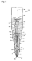
- Fig. 1 is a cross section view along a center axis of a valve showing a pilot-fuel injection valve applied to a gas engine concerning a first embodiment and a second embodiment of the present invention.
- Fig. 2 is a partial side view of said fuel injection valve, and Fig. 2A shows enlarged details of the parts Z and X in Fig.1 ; Fig. 2B shows an enlarged detail of the part Y in Fig.1 ;
- Fig. 3 shows a part of a cross section of the pilot-fuel injection valve around a needle valve and a sliding periphery thereof.
- the numeral 100 indicates an electromagnetic fuel injection valve assembly comprising a valve body 1, a nozzle tip 2 which is fluid-tightly fastened on to a bottom sealing face of a nozzle holder 6 by means of a nozzle nut 4 with a screw mechanism, a lower spacer 18 and an upper spacer 18a that are fluid-tightly pressed on a bottom sealing face of the valve body 1 by means of the nozzle nut 4 with a screw mechanism, a needle valve 3 which is inserted so as to slide with reciprocating movements into borehole formed in the nozzle tip 2 , a fuel pool 17, in the nozzle tip 2, communicated with a nozzle hole 2a which is perforated at a tip part (bottom front) of the nozzle tip 2, a center axis 1a of the fuel injection valve assembly 100, a pushrod 5 which is connected to an upper face of the needle valve 3, a needle valve spring 7 placed in between the pushrod 5 and a bottom face of the lower spacer 18 whereby the needle spring 7
- the needle valve opens the above-mentioned channel, the fuel accumulated from the fuel inlet 16 to the fuel pool 17 is injected into an engine cylinder room (not shown) through the nozzle hole 2a.
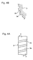
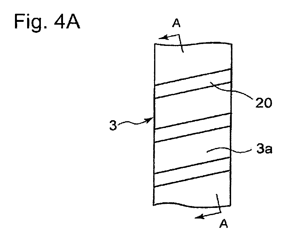
- Fig. 4A explains a first example of the needle valve, showing a part of a side view thereof and Fig. 4B shows an A-A cross-section view of Fig. 4A .
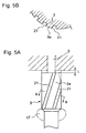
- Fig. 5A explains a second example of the needle valve, showing a part of a side view thereof and Fig. 5B shows a B-B cross-section view of Fig. 5A .
- Fig. 6 is an enlarged sectional view of a seat surface of the needle valve tip (a C-C cross section view of Fig. 7 and a D-D cross section view of Fig. 8 ), Fig. 7 is a partial side view showing the surface of the needle valve tip of a first example concerning the first embodiment, and Fig. 8 is a partial side view of the seal surface of the needle valve tip of a second example concerning the first embodiment.
- the above first embodiment combines the two; the needle valve described in Fig. 4A and Fig. 4B explaining the first example of the needle valve, and in Fig. 5A and Fig. 5B explaining the second example of the same; the seat surface in the nozzle tip of Fig. 6 and Fig. 7 which show the first example of the seat surface in the nozzle tip, and of Fig.6 and Fig 8 which show the second example of the same.
- a first groove is engraved on an outer surface 3a of the needle valve 3 so that the groove is connected to a fuel pool 17 at a lower end, and the fuel can be guided in the groove, while the groove is communicated with an outer space above an upper face of the needle valve.
- a spiral groove 20 as the first groove is formed on the outer surface of the needle valve, being placed spirally along the center axis of the needle valve; thereby, the spiral groove 20 is connected to a fuel pool 17 at a lower end, and the fuel can be guided in the groove, while the groove is communicated with an outer space above an upper face of the needle valve; consequently, the needle valve can be rotated in response to fuel movements in the groove 20.
- an inclined groove 21 that is formed on the outer surface of the needle valve; thereby, the inclined groove 21 as the first groove is connected to a fuel pool 17 at a lower end, and the fuel can be guided in the groove, while the groove is communicated with an outer space above an upper face of the needle valve; consequently, the needle valve can be rotated in response to fuel movements in the groove 20.
- a seat part (a seat cone 2z) of the nozzle tip comprises:
- the second grooves 22 are placed intermittently along discontiguous hoop circles (or a hoop circle) on the seat cone 2z.
- the second grooves 22 are placed side by side in inclined directions against hoop circles on the seat cone so that the lines (curves) of the grooves intersect the hoop circles (lines in hoop directions) 2y with an angle ⁇ ; hereupon, a plural rows of grooves may be replaced by one row groove.
- a part of the periphery contour of the second grooves 22 comprises a sharp edge 22a which scrapes-off depositing solid-materials of the fuel which adhere to the seat surfaces of the needle valve and the nozzle tip into the second grooves 22 with a help of the relative rotational movements of the needle valve 3 between the seat surfaces 3y and 2b.
- the second groove has preferably a cross section profile of a trapezoid broadening toward outside; however, the profile may be of a rectangle or of a crescent as long as a part of the periphery contour of the second groove 22 comprises the sharp edge 22a.
- the first groove is engraved on the outer periphery surface of the needle valve 3 so that the groove is connected to a fuel pool 17 at a lower end, and the fuel can be guided in the groove, while the groove is communicated with an outer space of an substantially ambient pressure, above an upper face of the needle valve 3; more specifically, as shown in Figs. 4A and 4B that depict the first example of the needle valve, the first groove is formed with a spiral groove 20, spirally along the center axis of the needle valve; or, as shown in Figs.
- the first groove is formed with a plurality of inclined grooves 21, the grooves being inclined against the needle longitudinal direction; hereupon, whether the first groove is the spiral groove 20 or the inclined groove 21, the needle valve 3 can be rotated in response to the reciprocating movements of the needle valve 3 as well as the movements of the fuel guided into the groove 20.
- a plurality of the second grooves 22 are engraved on the seat surface 2b of the nozzle tip 2 so that the second grooves 22 are placed along hoop circles of the needle valve rotation, or in uniformly-twisted or uniformly-inclined directions against the hoop directions, whereas a part of the periphery contour of the second groove 22 comprises a sharp edge 22a that scrapes-off depositing solid-materials in the fuel the materials which adhere to the seat surfaces of the needle valve 3 and the nozzle tip 2; more specifically, a plurality of the second grooves are provided intermittently along discontiguous hoop circles of the needle valve rotation, as shown in Figs.
- a part of fuel accumulated in the fuel pool 17 flows in the first groove (the spiral groove or the inclined groove) of the needle valve 3, and the groove which communicates the fuel pool 17 of a higher pressure to the space above the needle valve of a substantially ambient pressure; thereby, the fuel flow makes the needle valve rotate; in response to the rotational movements of the needle valve as well as through the fuel flow, easily can be carried away into the first groove the solid foreign matters such as foreign substances, impurities, or combustion residues in fuel the matters which are apt to enter a sliding clearance around the needle valve; further, the solid foreign matters can be easily discharged toward the air space of ambient pressures. Consequently, damage of the foreign matters on the outer surface of the needle valve can be evaded.
- the solid foreign matters denote substances such as foreign substances, impurities, or combustion residues in fuel the matters which are apt to enter a sliding clearance around the needle valve.
- Fig. 9A explains a first example of the needle valve showing a partial side view thereof concerning the second embodiment
- Fig. 9B is an E-E cross section view of Fig. 9A
- Fig. 10A explains a second example of the needle valve showing a partial side view thereof
- Fig. 10B is an F-F cross section view of Fig. 10A
- grooves 20 (22y) are engraved so that a part of fuel can flow therein; further, on the outer periphery 3a, a process of shot-peening 33 is performed.
- an axial direction groove 22y is engraved on the outer periphery 3a of the needle valve 3 in which the grooves 22y are connected to the fuel pool 17 at a lower end and connected to the outer space toward the air space so that a part of fuel can enter and go up the grooves 22y to be flown out to the outer space toward the air space.
- spiral grooves 20 are provided in a similar way shown in Figs. 4A and 4B (the first embodiment) in which the grooves 20 are connected to the fuel pool 17 at a lower end and connected to the outer space toward the air space so that a part of fuel can enter and go up the grooves 20 to be flown out to the outer space toward the air space.
- the above-mentioned first grooves can be alternated with a plurality of inclined grooves 21 as shown in Figs. 5A and 5B , in which the grooves 21 are connected to the fuel pool 17 at a lower end and connected to the outer space toward the air space.
- a process of shot-peening 33 is performed on the outer periphery 3a of the needle valve 3 where the grooves 21 are not engraved.
- the grooves are engraved on the outer periphery surface of the needle valve 3 so as to induce a part of fuel into the grooves; more specifically, the grooves are engraved as one of:
- a process of shot-peening 33 is performed on the outer periphery 3a of the needle valve 3 where the groove 21 is not engraved; thereby, fuel (as a certain lubricant) can be held within the microscopic depressions (dimples); thus, can be enhanced lubrication performance between the mutually sliding surfaces of the needle 3 outer periphery and the nozzle tip 2 bore; further, wear resistance as to the sliding surfaces is enhanced thanks to increased hardness of the needle outer periphery 3a.
- the second embodiment can be evaded inclusion of the solid foreign matters on the outer periphery 3a of the needle valve 3; whereby, the solid foreign matters denote substances such as foreign substances, impurities, or combustion residues in fuel; in addition, can be enhanced lubrication performance as well as wear resistance in relation to the mutually sliding surfaces of the needle 3 outer periphery and the nozzle tip 2 bore;
- the first groove in the present invention may optionally be provided on a control piston 8 shown in a detail X of Fig. 1 and in Fig. 2A ; whereby, fuel accumulated in a spring space 7z in which a needle valve spring 7 is accommodated is guided into this first groove.
- the present invention can provide a fuel injection valve that can prevent: an attack of solid foreign matters such as foreign substances, impurities, or combustion residues in fuel, on the contacting seat surfaces of a needle valve and/or a nozzle tip, and on the sliding surfaces of the needle valve periphery and/or a corresponding borehole in the nozzle tip, a malfunction and/or seizure of the needle valve through the mentioned attack, and incomplete combustion due to irregular injections.
Landscapes
- Engineering & Computer Science (AREA)
- Chemical & Material Sciences (AREA)
- Combustion & Propulsion (AREA)
- Mechanical Engineering (AREA)
- General Engineering & Computer Science (AREA)
- Physics & Mathematics (AREA)
- Electromagnetism (AREA)
- Fuel-Injection Apparatus (AREA)
Abstract
Description
- The present invention relates to a fuel injection valve such as a pilot fuel injection device in a gas engine or a fuel injection device in a diesel engine, whereby the injection valve injects fuel supplied in a fuel pool surrounding a needle valve into an engine cylinder room, and the injection valve stops the fuel injection in a way that a fuel flow channel between a tip of the needle valve and a valve seat of a nozzle tip is opened or closed by a reciprocating movement of the needle valve that is fitted slidably and guided in the nozzle tip.
- As is shown in a patent reference 1 (
JP2002-295342 - In a medium size or large size gas engine for generating and diesel engines, which are provided with the fuel injection valve as mentioned above, diesel oil is frequently used as a fuel (in large marine-diesel engines, heavy fuel oil and/or heavy duty fuel is usually used).
- The fuel used in the fuel injection valves for diesel fuel is apt to contain relatively large amount of foreign substances causing the foreign substances to often enter a sliding clearance around the needle valve. Moreover, impurities are sometimes brought into fuel oil during engine maintenance, and the fuel oil bringing the impurities into the sliding clearance around the needle valve. The above-mentioned foreign substances or impurities on the sliding surfaces often cause a malfunction, wear or seizure of the needle valve.
- When burnt, diesel oil generates more combustion residues than gas oil does; thus, in an injection valve of the engine that is operated with diesel oil, a considerable amount of combustion residues accumulates in the neighborhood of valve-seat surfaces around the needle valve which easily induces poor combustion caused by irregular injections because of the accumulated hard residues exfoliating from the surfaces and scratching the surfaces.
- The patent reference 1 (
JP2002-295342 - Another patent reference 2 (
JP2005-533222 - As mentioned above, in the fuel injection valves which use a fuel such as diesel oil containing relatively a large amount of foreign substances, the foreign substances or impurities brought by the fuel oil itself from the beginning or through engine maintenance work often enter the sliding clearance around the needle valve. Moreover, the diesel oil yields a considerable amount of combustion residues which are apt to damage the seat surfaces of the needle valve tip and/or the nozzle tip.
-
Fig. 11 shows an example of foreign substances distribution in a diesel oil sample and a gas oil sample. The data tells that the distribution quantity of the foreign substances in the diesel oil is 10 to 100 times higher than that in the gas oil when a particle size of the foreign substances is 5 to 15 µ m. - In the disclosure of the
patent reference 1, even though the needle valve is provided with a plurality of radial grooves around the outer periphery of the needle valve for a purpose of improving a lubricating condition between the periphery of the needle valve and the nozzle tip, the purpose of the grooves are mainly for improving lubrication by means of retaining fuel oil in the grooves. Thus, each groove is not opened toward outside, so foreign substances and/or impurities that are brought therein are apt to enter the sliding clearance around the needle valve through the reciprocating movements of the needle valve. Therefore, even with the technology disclosed in thepatent reference 1, intrusion of foreign substances and/or impurities into the sliding clearance around the needle valve still easily occurs, and the problems about malfunctions, wear or seizure of the needle valve periphery remain unsolved. - Further, in the disclosure of the
patent reference 2, a plurality of micro-depressions are configured on the seat surfaces of the needle valve tip and/or the nozzle tip so as to improve the lubricating condition by the fuel oil remaining in the depressions as a lubricant. However, the seat surface of the needle valve tip comes in contact with the seat surface of the nozzle tip so that the areas of contacting surfaces are kept substantially unchanged. Thus, when combustion residues, foreign substances, impurities and so on intrude into the seat areas, those solid foreign-matters are not removed from the micro-depressions, even if the depressions improve the lubrication. Consequently, there arise problems such as irregular fuel injections and poor combustion therewith, in response to the damage of the solid foreign matters on the seat surfaces. - The present invention is created in view of the mentioned technical background. Even in relation to the engines that use fuel including foreign substances to a considerable extent, the subject of the invention is to provide a fuel injection valve that can prevent:
- an attack of solid foreign matters such as foreign substances, impurities, or combustion residues on the contacting seat surfaces of a needle valve and/or a nozzle tip, and on the sliding surfaces of the needle valve periphery and/or a corresponding borehole in the nozzle tip,
- a malfunction and/or seizure of the needle valve through the mentioned attack, and
- poor combustion due to irregular injections.
- The disclosed invention to achieve the goals is a fuel injection valve that injects fuel supplied in a fuel pool surrounding a needle valve, into an engine cylinder room, through at least one nozzle hole perforated in the neighborhood of a tip of a nozzle tip, as well as shuts the injection, in a manner that a fuel flow passage between a seat surface of the needle valve tip and a seat surface of the nozzle tip is opened/closed by reciprocating movements of a needle valve fitted slidably in a borehole formed in the nozzle tip, comprising:
- said needle valve that comprises a first groove which is engraved on an outer periphery thereof so that fuel can be guided in the groove, the upper and lower ends of the groove being open toward outward; thereby, the needle valve can be rotated with the fuel flown in the groove in response to the reciprocating movements, and
- a nozzle tip that comprises a plurality of second grooves which are engraved on a seat surface therein so that the second grooves are arranged in a direction twisted or inclined in relation to hoop circles around an axis of the nozzle tip, as well as in relation to a rotational direction of the needle valve; whereby, the second groove comprises an sharp edge that scrapes-off depositing solid materials in the fuel the materials which adhere to the seat surfaces of the needle valve and the nozzle tip, into the second grooves, with the help of the relative rotational movements between the seat surfaces.
- In a preferable fuel injection valve according to the above, the first groove is connected to a fuel pool at one end so that fuel can be guided into the grooves, while the grooves are connected to a passage toward the outside over the needle valve.
- More specifically, the first groove preferably comprises one of:
- spiral grooves that are formed on the outer surface of the needle valve, being placed spirally along the center axis thereof, or
- inclined grooves that are formed on the outer surface of the needle valve, being inclined against the needle longitudinal direction;
- whereby, either grooves are connected to a fuel pool at a lower end so that fuel can be guided in the groove, while being connected to an upper end face of the needle valve.
- Further, the second groove preferably comprises one of:
- a plurality of grooves that are intermittently engraved on a seat surface of the nozzle tip, either along discontiguous hoop circles, or along a hoop circle, or
- a plurality of uninterrupted line grooves that are engraved on a seat surface of the nozzle tip, while being placed in inclined directions against hoop circles on the seat surface so that the lines (curves) of the grooves intersect the hoop circles with an inclined angle.
- According to the present invention, the first groove is engraved on the outer periphery surface of the needle valve so that the groove has open connections at lower/upper ends, and fuel can be guided in the groove; preferably, the first groove communicates with a fuel pool on a fuel passage in the injection valve, so as to induce fuel at an end of the groove, while the groove communicates with an outside, i.e. a space over the needle valve toward an air space; more specifically, the first groove is formed with a spiral groove, spirally along a center axis of the needle valve, or the first groove is formed with a plurality of inclined grooves, the grooves being inclined against the needle longitudinal direction; hereupon, the needle valve can be rotated in response to the reciprocating movements of the needle valve as well as the movements of the fuel guided into the first groove.
- Further, according to the present invention, a plurality of the second grooves are engraved on the seat surface of the nozzle tip so that the second grooves are placed along hoop circles of the needle valve rotation, or in uniformly-twisted or uniformly-inclined directions against the hoop directions, whereas a part of the periphery contour of the second groove comprises a sharp edge that scrapes-off depositing solid-materials in the fuel the materials which adhere to the seat surfaces of the needle valve and the nozzle tip; more specifically, a plurality of the second grooves are provided intermittently along hoop circles of the needle valve rotation, or a plurality of the second grooves are provided in uniformly-twisted or uniformly-inclined directions against the hoop directions as to the needle valve rotation.
- Further, a part of fuel accumulated in the
fuel pool 17 flows in the first groove of the needle valve the groove which communicates the fuel pool of a higher pressure in to a space over the needle valve, toward an air space; thereby, the fuel flow makes the needle valve rotate; in response to the rotational movements of the needle valve, easily can be carried away into the first groove the solid foreign matters such as foreign substances, impurities, or combustion residues in fuel the matters which are apt to enter a sliding clearance around the needle valve; further, the solid foreign matters can be easily discharged with the fuel flow toward the air space. Consequently, inclusion of the foreign matters on the outer surfaces around the needle valve can be evaded. - Thus, can be surely prevented a malfunction and/or seizure of the needle valve that are caused by inclusion of solid foreign matters in fuel; whereby, the solid foreign matters denote substances such as foreign substances impurities, or combustion residues.
- Moreover, through the rotational movements of the needle valve with the fuel flow in the first groove, as well as through the sharp edge (a keen edge part of whole contour edge) of a plurality of the second grooves that are provided on the seat surface of the nozzle tip, in uniformly-twisted or uniformly-inclined directions against the hoop directions as to the needle valve rotation the sharp edge which scrapes-off depositing solid-materials in the fuel the materials that adhere to the seat surfaces of the needle valve and the nozzle tip, solid-foreign substances are scraped-off into the second grooves the substances which are such as foreign substances, impurities, or combustion residues in fuel, and are apt to enter a sliding clearance between the tip part of the needle valve and the seat part (a seat cone) in the nozzle tip.
- As a result, an inclusion of the solid foreign-substances around the seat part can be withstood; an irregular injection thereby and an incomplete combustion therewith are prevented.
- Further, the present invention discloses a fuel injection valve that injects fuel supplied in a fuel pool on the way of a fuel passage in the injection valve, into an engine cylinder room, through at least one nozzle hole provided in the neighborhood of a tip of a nozzle tip, as well as stops the injection, in a manner that a needle valve opens/closes a fuel flow passage between a seat surface of the needle valve tip and a seat surface of the nozzle tip, by means of sliding along a borehole inside the nozzle tip with reciprocating movements; wherein, a groove is engraved on an outer periphery of the needle valve so that a part of fuel can flow in the groove, while a process of shot-peening is performed on the outer periphery.
- More specifically, the first groove preferably comprises one of:
- axial direction grooves that are formed on the outer surface of the needle valve, being placed along a center axis of the needle valve,
- spiral grooves that are formed on the outer surface of the needle valve, being placed spirally along the center axis of the needle valve, or
- inclined grooves that are formed on the outer surface of the needle valve, being inclined against the needle longitudinal direction as well as being connected to a fuel pool at a lower end so that fuel can be guided in the groove, while being connected to an upper end face of the needle valve, at an upper end of the inclined groove.
- According to the above invention, the groove is engraved on the outer periphery surface of the needle valve so as to induce a part of fuel in the groove; more specifically, the groove is engraved as one of:
- an axial direction groove that is formed on the outer surface of the needle valve, being placed along a center axis of the needle valve,
- a spiral groove that is formed on the outer surface of the needle valve, being placed spirally along the center axis of the needle valve, or
- an inclined groove that is formed on the outer surface of the needle valve, being inclined against the needle longitudinal direction as well as being connected to a fuel pool at a lower end so that fuel can be guided in the groove, while being connected to an upper end face of the needle valve, at an upper end of the inclined groove;
whereby, on the outer periphery of the needle valve where the groove is not engraved, a process of shot-peening is performed. - Consequently, solid foreign matters in fuel flow into the grooves; whereby, the solid foreign matters denote substances such as foreign substances, impurities, or combustion residues the substances that are apt to attack the outer periphery of the needle valve; thus, inclusion of the solid foreign matters on the outer periphery of the needle valve can be evaded; on the other hand, a process of shot-peening is performed on the outer periphery of the needle valve where the groove is not engraved; thereby, fuel (as a certain lubricant) can be held within the microscopic depressions (dimples); thus, can be enhanced lubrication performance between the mutually sliding surfaces of the needle outer periphery and the nozzle tip bore; further, wear resistance as to the sliding surfaces is enhanced thanks to increased hardness of the needle outer periphery.
- Thus, can be evaded inclusion of the solid foreign matters on the outer periphery of the needle valve; whereby, the solid foreign matters denote substances such as foreign substances, impurities, or combustion residues in fuel; in addition, can be enhanced lubrication performance as well as wear resistance in relation to the mutually sliding surfaces of the needle outer periphery and the nozzle tip bore.
- According to the present invention, a part of fuel accumulated in the fuel pool flows in the first groove of the needle valve the groove which communicates a higher pressure in the fuel pool to a space over the needle valve toward an air space; thereby, the fuel flow makes the needle valve rotate; in response to the rotational movements of the needle valve, easily can be carried away into the first groove solid foreign matters such as foreign substances, impurities, or combustion residues in fuel the matters which are apt to enter a sliding clearance around the needle valve; further, the solid foreign matters can be easily discharged with the fuel flow into the air space. Consequently, inclusion of the foreign matters on the outer surfaces around the needle valve can be evaded.
- Thus, can be surely prevented a malfunction and/or seizure of the needle valve that are caused by inclusion of solid foreign matters in the fuel such as foreign substances, impurities, or combustion residues in fuel.
- Moreover, according to the present invention, in response to the rotational movements of the needle valve with the fuel flow in the first groove, as well as through the sharp edge (a keen edge part of whole contour edge) of a plurality of the second grooves that are provided on the seat surface of the nozzle tip, in uniformly-twisted or uniformly-inclined directions against the hoop directions as to the needle valve rotation; thereby, the sharp edge scrapes-off depositing solid-materials in the fuel the materials that adhere to the seat surfaces of the needle valve and the nozzle tip, solid-foreign substances are scraped-off into the second grooves the substances which are such as combustion residues, foreign substances, or impurities in fuel, and are apt to enter a sliding clearance between the tip part of the needle valve and the seat part (a seat cone) in the nozzle tip.
- As a result, an inclusion of the solid foreign-substances around the seat part can be withstood; an irregular injection thereby and an incomplete combustion therewith are prevented.
- Further more, according to the present invention, thanks to the provided first grooves, solid foreign matters flow into the grooves; whereby, the solid foreign matters denote substances such as foreign substances, impurities, or combustion residues in fuel the substances which are apt to attack the outer periphery of the needle valve; thus, inclusion of the solid foreign matters on the outer periphery of the needle valve can be evaded; on the other hand, a process of shot-peening is performed on the outer periphery of the needle valve where the groove is not engraved; thereby, fuel (as a certain lubricant) can be held within the microscopic depressions (dimples) ; thus, can be enhanced lubrication performance between the mutually sliding surfaces of the needle-outer-periphery and the nozzle tip bore; further, wear resistance as to the sliding surfaces is enhanced due to increased hardness of the needle-outer-periphery.
- In this way, can be evaded inclusion of the solid foreign matters on the outer periphery of the needle valve; whereby, the solid foreign matters denote substances such as foreign substances, impurities, or combustion residues in fuel; in addition, can be enhanced lubrication performance as well as wear resistance in relation to the mutually sliding surfaces of the needle outer periphery and the nozzle tip bore.
-
-
Fig. 1 is a cross section view of a pilot-fuel injection valve applied to a gas engine, along a center axis of the valve, -
Fig. 2A shows enlarged details of the parts Z and X inFig.1 ,Fig. 2B shows an enlarged detail of the part Y inFig.1 , -
Fig. 3 is a partial cross section view of the pilot-fuel injection valve around a needle valve and a sliding periphery thereof, -
Fig. 4A explains a first example of the needle valve concerning the first embodiment, showing a part of a side view thereof,Fig. 4B is an A-A cross section view ofFig. 4A ; -
Fig. 5A explains a first example of the needle valve concerning the first embodiment, showing a part of a side view thereof,Fig. 5B is a B-B cross section view ofFig. 5A , -
Fig. 6 is an enlarged sectional view of a seat surface of the needle valve tip (a C-C cross section view ofFig. 7 and a D-D cross section view ofFig. 8 ). -
Fig. 7 is a partial side view showing the surface of the needle valve tip of a first example concerning the first embodiment, -
Fig. 8 is a partial side view of the seal surface of the needle valve tip of a second example concerning the first embodiment, -
Fig. 9A explains a first example of the needle valve showing a partial side view thereof concerning the second embodiment, -
Fig. 9B is an E-E cross section view ofFig. 9A , -
Fig. 10A explains a second example of the needle valve showing a partial side view thereof,Fig. 10B is an F-F cross section view ofFig. 10A , and -
Fig. 11 shows an example of measured foreign substances distribution as to a diesel oil sample and a gas oil sample. - Preferred embodiments of the present invention will now be detailed with reference to the accompanying drawings. It is intended, however, that unless particularly specified, dimensions, materials, relative positions and so forth of the constituent parts in the embodiments shall be interpreted as illustrative only not as limitative of the scope of the present invention.
-
Fig. 1 is a cross section view along a center axis of a valve showing a pilot-fuel injection valve applied to a gas engine concerning a first embodiment and a second embodiment of the present invention.Fig. 2 is a partial side view of said fuel injection valve, andFig. 2A shows enlarged details of the parts Z and X inFig.1 ;Fig. 2B shows an enlarged detail of the part Y inFig.1 ;Fig. 3 shows a part of a cross section of the pilot-fuel injection valve around a needle valve and a sliding periphery thereof. - In
Figs. 1 to 3 , the numeral 100 indicates an electromagnetic fuel injection valve assembly comprising
avalve body 1,
anozzle tip 2 which is fluid-tightly fastened on to a bottom sealing face of anozzle holder 6 by means of anozzle nut 4 with a screw mechanism,
alower spacer 18 and anupper spacer 18a that are fluid-tightly pressed on a bottom sealing face of thevalve body 1 by means of thenozzle nut 4 with a screw mechanism,
aneedle valve 3 which is inserted so as to slide with reciprocating movements into borehole formed in thenozzle tip 2 ,
afuel pool 17, in thenozzle tip 2, communicated with anozzle hole 2a which is perforated at a tip part (bottom front) of thenozzle tip 2,
acenter axis 1a of the fuelinjection valve assembly 100,
apushrod 5 which is connected to an upper face of theneedle valve 3,
aneedle valve spring 7 placed in between thepushrod 5 and a bottom face of thelower spacer 18 whereby theneedle spring 7 biases theneedle valve 3 in a direction to close the injection via thepushrod 5,
acontrol piston 8 that is engaged in a borehole of thelower spacer 18 so as to slide therein, a lower end part of thepiston 8 coming into contact with thepushrod 5,
afuel inlet 16 that is provided in a lateral part of thevalve body 1, communicating with thefuel pool 17 through anupper fuel passage 15 perforated in thevalve body 1, the upper/lower spacers 18a/18, and thenozzle holder 6 as well as alower fuel passage 13 perforated in thenozzle tip 2,
asolenoid 12,
anarmature 11,
a connecting rod 9 that is connected to thearmature 11,
areturn spring 10 that is placed in between the connecting rod 9 and thevalve body 1. - In the above-described electromagnetic
fuel injection valve 100, when thesolenoid 12 is excited and draws thearmature 11 upward, the connecting rod 9 moves upward against a spring force of thereturn spring 10; consequently, theneedle valve 3 moves upward against a spring force of theneedle valve spring 7; thus, theneedle valve 3 opens a fuel flow channel between a seat surface of the needle valve and a valve seat of the nozzle tip. - When the needle valve opens the above-mentioned channel, the fuel accumulated from the
fuel inlet 16 to thefuel pool 17 is injected into an engine cylinder room (not shown) through thenozzle hole 2a. - Referring to the first embodiment,
Fig. 4A explains a first example of the needle valve, showing a part of a side view thereof andFig. 4B shows an A-A cross-section view ofFig. 4A . Referring to the first embodiment,Fig. 5A explains a second example of the needle valve, showing a part of a side view thereof andFig. 5B shows a B-B cross-section view ofFig. 5A . - Further, concerning the first embodiment,
Fig. 6 is an enlarged sectional view of a seat surface of the needle valve tip (a C-C cross section view ofFig. 7 and a D-D cross section view ofFig. 8 ),Fig. 7 is a partial side view showing the surface of the needle valve tip of a first example concerning the first embodiment, andFig. 8 is a partial side view of the seal surface of the needle valve tip of a second example concerning the first embodiment. - The above first embodiment combines the two; the needle valve described in
Fig. 4A and Fig. 4B explaining the first example of the needle valve, and inFig. 5A and Fig. 5B explaining the second example of the same; the seat surface in the nozzle tip ofFig. 6 and Fig. 7 which show the first example of the seat surface in the nozzle tip, and ofFig.6 andFig 8 which show the second example of the same. - Namely, in the first embodiment of the
needle valve 3, a first groove is engraved on anouter surface 3a of theneedle valve 3 so that the groove is connected to afuel pool 17 at a lower end, and the fuel can be guided in the groove, while the groove is communicated with an outer space above an upper face of the needle valve. - More specifically, in the first example of the first embodiment of the
needle valve 3 as shown inFigs. 4A and 4B , aspiral groove 20 as the first groove is formed on the outer surface of the needle valve, being placed spirally along the center axis of the needle valve; thereby, thespiral groove 20 is connected to afuel pool 17 at a lower end, and the fuel can be guided in the groove, while the groove is communicated with an outer space above an upper face of the needle valve; consequently, the needle valve can be rotated in response to fuel movements in thegroove 20. - Further, in the second example of the first embodiment of the
needle valve 3 as shown inFigs. 5A and 5B , aninclined groove 21 that is formed on the outer surface of the needle valve; thereby, theinclined groove 21 as the first groove is connected to afuel pool 17 at a lower end, and the fuel can be guided in the groove, while the groove is communicated with an outer space above an upper face of the needle valve; consequently, the needle valve can be rotated in response to fuel movements in thegroove 20. - In addition, in the first embodiment, a seat part (a
seat cone 2z) of the nozzle tip comprises: - a
seat surface 2b of thenozzle tip 2 which aseat surface 3y of theneedle valve 3 comes in contact with, and - a plurality of second grooves engraved on the
surface 2b, thereby thesecond grooves 22 are placed along hoop circles of the valve needle rotation, or uniformly-twisted or uniformly-inclined directions against the hoop direction. - In the first example in the first embodiment of the seat part as shown in
Figs. 6 and 7 , thesecond grooves 22 are placed intermittently along discontiguous hoop circles (or a hoop circle) on theseat cone 2z. - Further, in the second example as shown in
Figs. 6 and8 , thesecond grooves 22 are placed side by side in inclined directions against hoop circles on the seat cone so that the lines (curves) of the grooves intersect the hoop circles (lines in hoop directions) 2y with an angle α; hereupon, a plural rows of grooves may be replaced by one row groove. - Moreover, in both the first example and the second example, a part of the periphery contour of the
second grooves 22 comprises asharp edge 22a which scrapes-off depositing solid-materials of the fuel which adhere to the seat surfaces of the needle valve and the nozzle tip into thesecond grooves 22 with a help of the relative rotational movements of theneedle valve 3 between the seat surfaces 3y and 2b. - As shown in
Fig. 6 , the second groove has preferably a cross section profile of a trapezoid broadening toward outside; however, the profile may be of a rectangle or of a crescent as long as a part of the periphery contour of thesecond groove 22 comprises thesharp edge 22a. - According to the above first embodiment, the first groove is engraved on the outer periphery surface of the
needle valve 3 so that the groove is connected to afuel pool 17 at a lower end, and the fuel can be guided in the groove, while the groove is communicated with an outer space of an substantially ambient pressure, above an upper face of theneedle valve 3; more specifically, as shown inFigs. 4A and 4B that depict the first example of the needle valve, the first groove is formed with aspiral groove 20, spirally along the center axis of the needle valve; or, as shown inFigs. 5A and 5B that depict the second example of the needle valve, the first groove is formed with a plurality ofinclined grooves 21, the grooves being inclined against the needle longitudinal direction; hereupon, whether the first groove is thespiral groove 20 or theinclined groove 21, theneedle valve 3 can be rotated in response to the reciprocating movements of theneedle valve 3 as well as the movements of the fuel guided into thegroove 20. - Further, according to the above first embodiment, a plurality of the
second grooves 22 are engraved on theseat surface 2b of thenozzle tip 2 so that thesecond grooves 22 are placed along hoop circles of the needle valve rotation, or in uniformly-twisted or uniformly-inclined directions against the hoop directions, whereas a part of the periphery contour of thesecond groove 22 comprises asharp edge 22a that scrapes-off depositing solid-materials in the fuel the materials which adhere to the seat surfaces of theneedle valve 3 and thenozzle tip 2; more specifically, a plurality of the second grooves are provided intermittently along discontiguous hoop circles of the needle valve rotation, as shown inFigs. 6 and 7 as to the first mode in the first embodiment of the seat part (seat cone), or a plurality of the second grooves are provided in uniformly-twisted or uniformly-inclined directions against the hoop directions as to the needle valve rotation, as shown inFigs. 6 and8 as to the second example in the first embodiment of the seat part (seat cone). - On the other hand, a part of fuel accumulated in the
fuel pool 17 flows in the first groove (the spiral groove or the inclined groove) of theneedle valve 3, and the groove which communicates thefuel pool 17 of a higher pressure to the space above the needle valve of a substantially ambient pressure; thereby, the fuel flow makes the needle valve rotate; in response to the rotational movements of the needle valve as well as through the fuel flow, easily can be carried away into the first groove the solid foreign matters such as foreign substances, impurities, or combustion residues in fuel the matters which are apt to enter a sliding clearance around the needle valve; further, the solid foreign matters can be easily discharged toward the air space of ambient pressures. Consequently, damage of the foreign matters on the outer surface of the needle valve can be evaded. - Thus, can be surely prevented a malfunction and/or seizure of the needle valve that are caused by inclusion of solid foreign matters in the fuel; whereby, the solid foreign matters denote substances such as foreign substances, impurities, or combustion residues in fuel the matters which are apt to enter a sliding clearance around the needle valve.
- Through the rotational movements of the
needle valve 3 with the fuel flow in the first groove, as well as through the sharp edge (a keen edge part of whole contour edge) 22a of the second grooves (a plurality of the second grooves) that are provided in uniformly-twisted or uniformly-inclined directions against the hoop directions as to the needle valve rotation; thereby, the sharp edge scrapes-off depositing solid-materials in the fuel the materials that adhere to the seat surfaces of theneedle valve 3 and thenozzle tip 2, solid-foreign substances are scraped-off into the second grooves the substances which are such as foreign substances, impurities, or combustion residues in fuel, and are apt to enter a sliding clearance between the tip part of theneedle valve 3 and theseat part 2z (a seat cone) in thenozzle tip 2. - As a result, an inclusion of the solid foreign-substances around the
seat part 2z can be withstood; an irregular injection thereby and an incomplete combustion therewith are prevented. - Concerning the second embodiment,
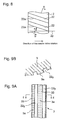
Fig. 9A explains a first example of the needle valve showing a partial side view thereof concerning the second embodiment, andFig. 9B is an E-E cross section view ofFig. 9A . Concerning the second embodiment,Fig. 10A explains a second example of the needle valve showing a partial side view thereof,Fig. 10B is an F-F cross section view ofFig. 10A - In this second embodiment, on an
outer periphery 3a of the needle,valve 3, grooves 20 (22y) are engraved so that a part of fuel can flow therein; further, on theouter periphery 3a, a process of shot-peening 33 is performed. - Namely, as shown in
Figs. 9A and 9B , in a first example of the second embodiment, anaxial direction groove 22y is engraved on theouter periphery 3a of theneedle valve 3 in which thegrooves 22y are connected to thefuel pool 17 at a lower end and connected to the outer space toward the air space so that a part of fuel can enter and go up thegrooves 22y to be flown out to the outer space toward the air space. - On the
outer periphery 3a of theneedle valve 3 where thegrooves 22y are not engraved, a process of shot-peening 33 is performed. - As shown in
Figs. 10A and 10B , in a second example of the second embodiment as to theneedle valve 3, on theouter periphery 3a of theneedle valve 3,spiral grooves 20 are provided in a similar way shown inFigs. 4A and 4B (the first embodiment) in which thegrooves 20 are connected to thefuel pool 17 at a lower end and connected to the outer space toward the air space so that a part of fuel can enter and go up thegrooves 20 to be flown out to the outer space toward the air space. - Further, on the
outer periphery 3a of theneedle valve 3 where thegrooves 20 are not engraved, a process of shot-peening 33 is performed. - Moreover, although an explanation figure is omitted, the above-mentioned first grooves (the spiral grooves 20) can be alternated with a plurality of
inclined grooves 21 as shown inFigs. 5A and 5B , in which thegrooves 21 are connected to thefuel pool 17 at a lower end and connected to the outer space toward the air space. Again, on theouter periphery 3a of theneedle valve 3 where thegrooves 21 are not engraved, a process of shot-peening 33 is performed. - According to the above second embodiment, the grooves are engraved on the outer periphery surface of the
needle valve 3 so as to induce a part of fuel into the grooves; more specifically, the grooves are engraved as one of: - a plurality of
axial direction grooves 22y that is formed on the outer surface of the needle valve, being placed along a center axis of the needle valve, -
spiral grooves 20 formed on the outer surface of the needle valve, being placed spirally along the center axis of the needle valve, or - inclined grooves 21 (as shown in
Figs. 5A and 5B ) that are formed on the outer surface of the needle valve, being inclined against the needle longitudinal direction and also being connected to the fuel pool at a lower end so that fuel can be guided into the grooves, while being connected to the upper end face of the valve needle at an upper end of the inclined groove. - Consequently, due to the shot-peening 33 performed on the
outer periphery 3a, solid foreign matters such as foreign substances, impurities, or combustion residues, which are apt to enter theouter periphery 3a, flow into thegrooves outer periphery 3a of theneedle valve 3. Moreover on the other hand, a process of shot-peening 33 is performed on theouter periphery 3a of theneedle valve 3 where thegroove 21 is not engraved; thereby, fuel (as a certain lubricant) can be held within the microscopic depressions (dimples); thus, can be enhanced lubrication performance between the mutually sliding surfaces of theneedle 3 outer periphery and thenozzle tip 2 bore; further, wear resistance as to the sliding surfaces is enhanced thanks to increased hardness of the needleouter periphery 3a. - Conclusively, according to the second embodiment, can be evaded inclusion of the solid foreign matters on the
outer periphery 3a of theneedle valve 3; whereby, the solid foreign matters denote substances such as foreign substances, impurities, or combustion residues in fuel; in addition, can be enhanced lubrication performance as well as wear resistance in relation to the mutually sliding surfaces of theneedle 3 outer periphery and thenozzle tip 2 bore; - Besides the first and second embodiments, the first groove in the present invention may optionally be provided on a
control piston 8 shown in a detail X ofFig. 1 and inFig. 2A ; whereby, fuel accumulated in aspring space 7z in which aneedle valve spring 7 is accommodated is guided into this first groove. - Even in relation to the engines that use fuel containing foreign substances to a considerable extent the present invention can provide a fuel injection valve that can prevent: an attack of solid foreign matters such as foreign substances, impurities, or combustion residues in fuel, on the contacting seat surfaces of a needle valve and/or a nozzle tip, and on the sliding surfaces of the needle valve periphery and/or a corresponding borehole in the nozzle tip, a malfunction and/or seizure of the needle valve through the mentioned attack, and incomplete combustion due to irregular injections.
Claims (5)
- A fuel injection valve that injects fuel supplied in a fuel pool surrounding a needle valve, into an engine cylinder room, through at least one nozzle hole perforated in the neighborhood of a tip of a nozzle tip, as well as shuts the injection, in a manner that a fuel flow passage between a seat surface of the needle valve tip and a seat surface of the nozzle tip is opened/closed by reciprocating movements of a needle valve fitted slidably in a borehole formed in the nozzle tip, comprising:said needle valve that comprises a first groove which is engraved on an outer periphery thereof so that fuel can be guided in the groove, the upper and lower ends of the groove being open toward outward; thereby, the needle valve can be rotated with the fuel flown in the groove in response to the reciprocating movements, anda nozzle tip that comprises a plurality of second grooves which are engraved on a seat surface therein so that the second grooves are arranged in a direction twisted or inclined in relation to hoop circles around an axis of the nozzle tip, as well as in relation to a rotational direction of the needle valve; whereby, the second groove comprises an sharp edge that scrapes-off depositing solid materials in the fuel the materials which adhere to the seat surfaces of the needle valve and the nozzle tip, into the second grooves, with the help of the relative rotational movements between the seat surfaces.
- The fuel injection valve according to claim 1, wherein the first groove comprises:spiral grooves that are formed on the outer surface of the needle valve, being placed spirally along the center axis thereof, orinclined grooves that are formed on the outer surface of the needle valve, being inclined against the needle longitudinal direction;whereby, either grooves are connected to a fuel pool at a lower end so that fuel can be guided in the groove, while being connected to an upper end face of the needle valve.
- The fuel injection valve according to claim 1, wherein the second groove comprises:a plurality of grooves that are intermittently engraved on a seat surface of the nozzle tip, either along discontiguous hoop circles, or along a hoop circle, ora plurality of uninterrupted line grooves that are engraved on a seat surface of the nozzle tip, while being placed in inclined directions against hoop circles on the seat surface so that the lines (curves) of the grooves intersect the hoop circles with an inclined angle.
- A fuel injection valve that injects fuel supplied in a fuel pool surrounding a needle valve, into an engine cylinder room, through at least one nozzle hole perforated in the neighborhood of a tip of a nozzle tip, as well as shuts the injection, in a manner that a fuel flow passage between a seat surface of the needle valve tip and a seat surface of the nozzle tip is opened/closed by reciprocating movements of a needle valve fitted slidably in a borehole formed in the nozzle tip, comprising:a needle valve that comprises grooves which are engraved on an outer periphery thereof so that fuel can be guided in the grooves, and an outer periphery surface which a shot-peening performed on in a place where the grooves are not engraved.
- The fuel injection valve according to claim 4, wherein the grooves comprise one of:a plurality of axial direction grooves that are formed on the outer surface of the needle valve, being placed along a center axis of the needle valve,spiral grooves that are formed on the outer surface of the needle valve, being placed spirally along the center axis of the needle valve, orinclined grooves that are formed on the outer surface of the needle valve, being inclined against the needle longitudinal direction as well as being connected to a fuel pool at a lower end so that fuel can be guided in the groove, while being connected to an upper end face of the needle valve, at an upper end of the inclined groove.
Applications Claiming Priority (2)
| Application Number | Priority Date | Filing Date | Title |
|---|---|---|---|
| JP2006236064A JP2008057458A (en) | 2006-08-31 | 2006-08-31 | Fuel injection valve |
| PCT/JP2007/065672 WO2008026438A1 (en) | 2006-08-31 | 2007-08-03 | Fuel injection valve |
Publications (3)
| Publication Number | Publication Date |
|---|---|
| EP1965070A1 true EP1965070A1 (en) | 2008-09-03 |
| EP1965070A4 EP1965070A4 (en) | 2013-04-03 |
| EP1965070B1 EP1965070B1 (en) | 2018-11-21 |
Family
ID=39135724
Family Applications (1)
| Application Number | Title | Priority Date | Filing Date |
|---|---|---|---|
| EP07792318.3A Ceased EP1965070B1 (en) | 2006-08-31 | 2007-08-03 | Fuel injection valve |
Country Status (5)
| Country | Link |
|---|---|
| US (2) | US7654475B2 (en) |
| EP (1) | EP1965070B1 (en) |
| JP (1) | JP2008057458A (en) |
| CN (1) | CN101365874B (en) |
| WO (1) | WO2008026438A1 (en) |
Cited By (3)
| Publication number | Priority date | Publication date | Assignee | Title |
|---|---|---|---|---|
| EP2824311A1 (en) * | 2013-07-10 | 2015-01-14 | EFI Hightech AG | Piston element assembly, and fuel injector with a piston element assembly |
| EP3596333A1 (en) * | 2017-03-13 | 2020-01-22 | A.P. Møller - Mærsk A/S | Valve needle |
| GB2585064A (en) * | 2019-06-27 | 2020-12-30 | Delphi Tech Ip Ltd | Common Rail System |
Families Citing this family (12)
| Publication number | Priority date | Publication date | Assignee | Title |
|---|---|---|---|---|
| WO2011125154A1 (en) * | 2010-04-02 | 2011-10-13 | トヨタ自動車株式会社 | Fuel injection valve and fuel injection device |
| JP2012007529A (en) * | 2010-06-24 | 2012-01-12 | Toyota Motor Corp | Fuel injection valve |
| KR101154579B1 (en) * | 2010-11-23 | 2012-06-08 | 현대자동차주식회사 | Injector Hole Structure for Engine |
| DE102011051904A1 (en) * | 2011-07-18 | 2012-06-21 | L'orange Gmbh | Device i.e. nozzle element, for use in fuel injection system, has structures formed at surfaces of guiding path and/or lifting rod and comprising and/or formed by trimming edges that traverse each other based on stroke position |
| PL220085B1 (en) * | 2012-03-15 | 2015-08-31 | Akademia Morska W Szczecinie | Fuel Injector |
| CN102758713B (en) * | 2012-07-26 | 2015-09-30 | 任一虎 | Electrically controlled dual-fuel injector assembly and method of work thereof |
| JP5983535B2 (en) * | 2013-05-22 | 2016-08-31 | トヨタ自動車株式会社 | Fuel injection valve |
| CN104632487A (en) * | 2015-02-06 | 2015-05-20 | 中国重汽集团重庆燃油喷射系统有限公司 | Oil nozzle with spiral groove structure |
| CN105065166B (en) * | 2015-08-12 | 2018-02-23 | 江苏大学 | Needle-valve, pintle nozzle match-ing parts and the needle-valve processing method of diesel injector |
| DE102018104835A1 (en) * | 2018-03-02 | 2019-09-05 | Atlas Copco Ias Gmbh | Device for applying a viscous material to workpieces |
| CN110805512A (en) * | 2018-08-05 | 2020-02-18 | 大连理工大学 | Nozzle with torsional composite hole |
| CN114992025B (en) * | 2022-06-09 | 2023-10-31 | 北京航空航天大学 | Aeroengine fuel injector matching part adapting to carbon-negative biofuel supply |
Family Cites Families (27)
| Publication number | Priority date | Publication date | Assignee | Title |
|---|---|---|---|---|
| US3398936A (en) * | 1966-08-02 | 1968-08-27 | Curtiss Wright Corp | Fuel injection pintle |
| DE2543805C2 (en) * | 1975-10-01 | 1986-05-07 | Robert Bosch Gmbh, 7000 Stuttgart | Electromagnetically actuated injection valve |
| US4899699A (en) * | 1988-03-09 | 1990-02-13 | Chinese Petroleum Company | Low pressure injection system for injecting fuel directly into cylinder of gasoline engine |
| EP0570640B1 (en) * | 1992-05-20 | 1997-06-18 | Shinichi Tashiro | Carburettor and fuel feeding system having the same |
| JPH07103106A (en) | 1993-09-30 | 1995-04-18 | Hino Motors Ltd | Fuel injection device |
| JPH08193560A (en) * | 1994-11-15 | 1996-07-30 | Zexel Corp | Variable nozzle hole type fuel injection nozzle |
| DE19547423B4 (en) * | 1995-12-19 | 2008-09-18 | Robert Bosch Gmbh | Fuel injection valve for internal combustion engines |
| US5947389A (en) * | 1996-06-06 | 1999-09-07 | Zexel Corporation | Variable nozzle hole type fuel injection nozzle |
| JPH10141179A (en) * | 1996-11-08 | 1998-05-26 | Zexel Corp | Fuel injection nozzle |
| JPH10196490A (en) * | 1997-01-14 | 1998-07-28 | Zexel Corp | Fuel injection nozzle |
| JPH1182229A (en) * | 1997-09-08 | 1999-03-26 | Unisia Jecs Corp | Fuel injector |
| JPH11230006A (en) | 1998-02-18 | 1999-08-24 | Denso Corp | Fuel injection valve |
| EP1066466B1 (en) * | 1998-03-26 | 2002-10-16 | MTU Friedrichshafen GmbH | High-pressure piston cylinder unit |
| JPH11294300A (en) * | 1998-04-09 | 1999-10-26 | Denso Corp | Fuel injection valve |
| DE19843344A1 (en) * | 1998-09-22 | 2000-03-23 | Bosch Gmbh Robert | Fuel injection valve for internal combustion engine has valve member axially movably positioned in bore of valve body, which has valve sealing surface at combustion chamber-side end |
| US6776358B2 (en) * | 1998-10-09 | 2004-08-17 | Jun Arimoto | Fuel injection nozzle for a diesel engine |
| AUPQ708100A0 (en) * | 2000-04-20 | 2000-05-18 | Orbital Engine Company (Australia) Proprietary Limited | Deposit control in fuel injector nozzles |
| DE10024854C2 (en) * | 2000-05-19 | 2002-11-28 | Siemens Ag | Valve needle and valve control piston of injectors |
| DE10102234A1 (en) * | 2001-01-19 | 2002-07-25 | Bosch Gmbh Robert | High pressure fuel supply unit, for an IC motor with fuel injection, has a drilling through the valve body to take a piston with a sealing section against the guide section of the drilling, with a hydraulic piston centering action |
| JP3825270B2 (en) | 2001-03-30 | 2006-09-27 | 三菱重工業株式会社 | Structure of fuel injection valve |
| DE10232050A1 (en) * | 2002-07-16 | 2004-02-05 | Robert Bosch Gmbh | Fuel injection valve, for an IC motor, has micro-recesses in the valve needle sealing surface and/or the valve seat to improve the drift behavior of the injected fuel volume and increase the working life |
| DE10313225A1 (en) * | 2003-03-25 | 2004-10-07 | Robert Bosch Gmbh | Fuel injection valve for internal combustion engines |
| DE10351881A1 (en) * | 2003-10-30 | 2005-06-02 | Robert Bosch Gmbh | Injector with structures for limiting wear-related changes of an opening course |
| DE10353683A1 (en) * | 2003-11-17 | 2005-06-16 | Robert Bosch Gmbh | Fuel injection valve for internal combustion engines |
| CN1570372A (en) * | 2004-05-10 | 2005-01-26 | 李明海 | Needle valve pair with forced lubrication and cooling |
| JP3989495B2 (en) * | 2004-09-22 | 2007-10-10 | トヨタ自動車株式会社 | Fuel injection device |
| US7540271B2 (en) * | 2007-04-25 | 2009-06-02 | Advanced Global Equities And Intellectual Properties, Inc. | Fuel injection lubrication mechanism for continuous self lubrication of a fuel injector |
-
2006
- 2006-08-31 JP JP2006236064A patent/JP2008057458A/en not_active Withdrawn
-
2007
- 2007-08-03 CN CN2007800019491A patent/CN101365874B/en not_active Expired - Fee Related
- 2007-08-03 US US12/086,629 patent/US7654475B2/en not_active Expired - Fee Related
- 2007-08-03 WO PCT/JP2007/065672 patent/WO2008026438A1/en not_active Ceased
- 2007-08-03 EP EP07792318.3A patent/EP1965070B1/en not_active Ceased
-
2009
- 2009-03-23 US US12/408,940 patent/US20090184180A1/en not_active Abandoned
Cited By (9)
| Publication number | Priority date | Publication date | Assignee | Title |
|---|---|---|---|---|
| EP2824311A1 (en) * | 2013-07-10 | 2015-01-14 | EFI Hightech AG | Piston element assembly, and fuel injector with a piston element assembly |
| WO2015004189A1 (en) * | 2013-07-10 | 2015-01-15 | Efi Hightech Ag | Surface structures on hardened inner and outer surfaces of guide elements in the high-pressure range, especially a piston element arrangement, and injection nozzle having a piston element arrangement |
| EP3596333A1 (en) * | 2017-03-13 | 2020-01-22 | A.P. Møller - Mærsk A/S | Valve needle |
| US10890150B2 (en) | 2017-03-13 | 2021-01-12 | A.P. Møller—Mærsk A/S | Fuel injection valve |
| US10890149B2 (en) | 2017-03-13 | 2021-01-12 | A.P. Møller—Mærsk A/S | Fuel supply valve for a slurry fuel injector valve |
| US11162466B2 (en) | 2017-03-13 | 2021-11-02 | A.P. Møller—Mærsk A/S | Fuel injection system |
| US11268484B2 (en) | 2017-03-13 | 2022-03-08 | A.P. Møller—Mærsk A/S | Valve needle |
| GB2585064A (en) * | 2019-06-27 | 2020-12-30 | Delphi Tech Ip Ltd | Common Rail System |
| GB2585064B (en) * | 2019-06-27 | 2021-11-10 | Delphi Tech Ip Ltd | Fuel injector with closed loop detection |
Also Published As
| Publication number | Publication date |
|---|---|
| US20090184180A1 (en) | 2009-07-23 |
| JP2008057458A (en) | 2008-03-13 |
| CN101365874A (en) | 2009-02-11 |
| EP1965070B1 (en) | 2018-11-21 |
| US20080308657A1 (en) | 2008-12-18 |
| WO2008026438A1 (en) | 2008-03-06 |
| EP1965070A4 (en) | 2013-04-03 |
| CN101365874B (en) | 2011-07-06 |
| US7654475B2 (en) | 2010-02-02 |
Similar Documents
| Publication | Publication Date | Title |
|---|---|---|
| EP1965070A1 (en) | Fuel injection valve | |
| EP1579137B1 (en) | Valve for controlling a fluid | |
| US20110079302A1 (en) | Pump Valve with Full Elastomeric Contact on Seat | |
| US20080264377A1 (en) | Fuel injection lubrication mechanism for continuous self lubrication of a fuel injector | |
| CN1934357A (en) | High-pressure pump, in particular for a fuel-injection device in an internal combustion engine | |
| CN1886590A (en) | Valve, in particular for a high-pressure pump of a fuel-injection device for an internal combustion engine | |
| CN101341329B (en) | High-pressure pump, in particular for a fuel injection device of an internal combustion engine | |
| CN206458552U (en) | Valve system, fuel injector system and containment member | |
| US6516765B1 (en) | Passively rotating valve | |
| EP1701007B1 (en) | Hydraulic valve lash adjuster | |
| US20080240952A1 (en) | High-Pressure Pump, in Particular for a Fuel Injection System of an Internal Combustion Engine | |
| DE10346211A1 (en) | Check valve, in particular for a high-pressure pump of a fuel injection device for an internal combustion engine | |
| CN100449140C (en) | Piston of high pressure piston in cylinder assembly | |
| DE102013010232A1 (en) | Check valve for a fuel system | |
| EP2333296B1 (en) | A Valve Member for a Fluid Valve Arrangement | |
| US6138643A (en) | Fuel injection device with oil seal | |
| DE102006004515B4 (en) | Dosing device for lubricating oil in valves | |
| EP1715176B1 (en) | Fuel injector having a free floating plunger | |
| US6837201B1 (en) | Apparatus and method for lessening the accumulation of high boiling fraction from fuel in intake valves of combustion engines | |
| EP1979605B1 (en) | Fuel injector | |
| CN100412353C (en) | A high-pressure common rail electronically controlled fuel injector sealing device | |
| CN1755098A (en) | fuel injection valve | |
| KR100420588B1 (en) | Cylinder Oil Injection Nozzle and Cylinder lubrication system for marine diesel Engine | |
| JPH07243355A (en) | Binary fluid injection valve | |
| KR200231065Y1 (en) | An check valve for a Oil jet |
Legal Events
| Date | Code | Title | Description |
|---|---|---|---|
| PUAI | Public reference made under article 153(3) epc to a published international application that has entered the european phase |
Free format text: ORIGINAL CODE: 0009012 |
|
| 17P | Request for examination filed |
Effective date: 20080626 |
|
| AK | Designated contracting states |
Kind code of ref document: A1 Designated state(s): AT BE BG CH CY CZ DE DK EE ES FI FR GB GR HU IE IS IT LI LT LU LV MC MT NL PL PT RO SE SI SK TR |
|
| AX | Request for extension of the european patent |
Extension state: AL BA HR MK RS |
|
| RBV | Designated contracting states (corrected) |
Designated state(s): CH DE FI LI |
|
| DAX | Request for extension of the european patent (deleted) | ||
| A4 | Supplementary search report drawn up and despatched |
Effective date: 20130305 |
|
| RIC1 | Information provided on ipc code assigned before grant |
Ipc: F02M 51/06 20060101ALI20130227BHEP Ipc: F02M 61/10 20060101AFI20130227BHEP Ipc: F02M 61/18 20060101ALI20130227BHEP Ipc: F02M 61/16 20060101ALI20130227BHEP |
|
| 17Q | First examination report despatched |
Effective date: 20140206 |
|
| RIC1 | Information provided on ipc code assigned before grant |
Ipc: F02M 51/06 20060101AFI20180213BHEP |
|
| REG | Reference to a national code |
Ref country code: DE Ref legal event code: R079 Ref document number: 602007056908 Country of ref document: DE Free format text: PREVIOUS MAIN CLASS: F02M0061100000 Ipc: F02M0051060000 |
|
| RAP1 | Party data changed (applicant data changed or rights of an application transferred) |
Owner name: MITSUBISHI HEAVY INDUSTRIES ENGINE & TURBOCHARGER, |
|
| GRAP | Despatch of communication of intention to grant a patent |
Free format text: ORIGINAL CODE: EPIDOSNIGR1 |
|
| RIC1 | Information provided on ipc code assigned before grant |
Ipc: F02M 61/16 20060101ALI20180620BHEP Ipc: F02M 61/04 20060101ALI20180620BHEP Ipc: F02M 61/18 20060101ALI20180620BHEP Ipc: F02M 51/06 20060101AFI20180620BHEP |
|
| INTG | Intention to grant announced |
Effective date: 20180723 |
|
| GRAS | Grant fee paid |
Free format text: ORIGINAL CODE: EPIDOSNIGR3 |
|
| GRAA | (expected) grant |
Free format text: ORIGINAL CODE: 0009210 |
|
| AK | Designated contracting states |
Kind code of ref document: B1 Designated state(s): CH DE FI LI |
|
| REG | Reference to a national code |
Ref country code: CH Ref legal event code: EP |
|
| REG | Reference to a national code |
Ref country code: DE Ref legal event code: R096 Ref document number: 602007056908 Country of ref document: DE |
|
| PG25 | Lapsed in a contracting state [announced via postgrant information from national office to epo] |
Ref country code: FI Free format text: LAPSE BECAUSE OF FAILURE TO SUBMIT A TRANSLATION OF THE DESCRIPTION OR TO PAY THE FEE WITHIN THE PRESCRIBED TIME-LIMIT Effective date: 20181121 |
|
| REG | Reference to a national code |
Ref country code: DE Ref legal event code: R097 Ref document number: 602007056908 Country of ref document: DE |
|
| PLBE | No opposition filed within time limit |
Free format text: ORIGINAL CODE: 0009261 |
|
| STAA | Information on the status of an ep patent application or granted ep patent |
Free format text: STATUS: NO OPPOSITION FILED WITHIN TIME LIMIT |
|
| 26N | No opposition filed |
Effective date: 20190822 |
|
| PG25 | Lapsed in a contracting state [announced via postgrant information from national office to epo] |
Ref country code: CH Free format text: LAPSE BECAUSE OF NON-PAYMENT OF DUE FEES Effective date: 20190831 Ref country code: LI Free format text: LAPSE BECAUSE OF NON-PAYMENT OF DUE FEES Effective date: 20190831 |
|
| PGFP | Annual fee paid to national office [announced via postgrant information from national office to epo] |
Ref country code: DE Payment date: 20200722 Year of fee payment: 14 |
|
| REG | Reference to a national code |
Ref country code: DE Ref legal event code: R119 Ref document number: 602007056908 Country of ref document: DE |
|
| PG25 | Lapsed in a contracting state [announced via postgrant information from national office to epo] |
Ref country code: DE Free format text: LAPSE BECAUSE OF NON-PAYMENT OF DUE FEES Effective date: 20220301 |