EP1964778B1 - Pivot traversant à lames - Google Patents
Pivot traversant à lames Download PDFInfo
- Publication number
- EP1964778B1 EP1964778B1 EP08102032A EP08102032A EP1964778B1 EP 1964778 B1 EP1964778 B1 EP 1964778B1 EP 08102032 A EP08102032 A EP 08102032A EP 08102032 A EP08102032 A EP 08102032A EP 1964778 B1 EP1964778 B1 EP 1964778B1
- Authority
- EP
- European Patent Office
- Prior art keywords
- rotation
- rotor
- pivot
- stator
- flexible elements
- Prior art date
- Legal status (The legal status is an assumption and is not a legal conclusion. Google has not performed a legal analysis and makes no representation as to the accuracy of the status listed.)
- Active
Links
- 238000005452 bending Methods 0.000 description 2
- 230000005540 biological transmission Effects 0.000 description 1
- 238000012937 correction Methods 0.000 description 1
- 238000002513 implantation Methods 0.000 description 1
- 230000002427 irreversible effect Effects 0.000 description 1
Images

Classifications
-
- B—PERFORMING OPERATIONS; TRANSPORTING
- B64—AIRCRAFT; AVIATION; COSMONAUTICS
- B64G—COSMONAUTICS; VEHICLES OR EQUIPMENT THEREFOR
- B64G1/00—Cosmonautic vehicles
- B64G1/22—Parts of, or equipment specially adapted for fitting in or to, cosmonautic vehicles
- B64G1/66—Arrangements or adaptations of apparatus or instruments, not otherwise provided for
-
- F—MECHANICAL ENGINEERING; LIGHTING; HEATING; WEAPONS; BLASTING
- F16—ENGINEERING ELEMENTS AND UNITS; GENERAL MEASURES FOR PRODUCING AND MAINTAINING EFFECTIVE FUNCTIONING OF MACHINES OR INSTALLATIONS; THERMAL INSULATION IN GENERAL
- F16C—SHAFTS; FLEXIBLE SHAFTS; ELEMENTS OR CRANKSHAFT MECHANISMS; ROTARY BODIES OTHER THAN GEARING ELEMENTS; BEARINGS
- F16C11/00—Pivots; Pivotal connections
- F16C11/04—Pivotal connections
- F16C11/12—Pivotal connections incorporating flexible connections, e.g. leaf springs
-
- F—MECHANICAL ENGINEERING; LIGHTING; HEATING; WEAPONS; BLASTING
- F16—ENGINEERING ELEMENTS AND UNITS; GENERAL MEASURES FOR PRODUCING AND MAINTAINING EFFECTIVE FUNCTIONING OF MACHINES OR INSTALLATIONS; THERMAL INSULATION IN GENERAL
- F16C—SHAFTS; FLEXIBLE SHAFTS; ELEMENTS OR CRANKSHAFT MECHANISMS; ROTARY BODIES OTHER THAN GEARING ELEMENTS; BEARINGS
- F16C2326/00—Articles relating to transporting
- F16C2326/47—Cosmonautic vehicles, i.e. bearings adapted for use in outer-space
-
- Y—GENERAL TAGGING OF NEW TECHNOLOGICAL DEVELOPMENTS; GENERAL TAGGING OF CROSS-SECTIONAL TECHNOLOGIES SPANNING OVER SEVERAL SECTIONS OF THE IPC; TECHNICAL SUBJECTS COVERED BY FORMER USPC CROSS-REFERENCE ART COLLECTIONS [XRACs] AND DIGESTS
- Y10—TECHNICAL SUBJECTS COVERED BY FORMER USPC
- Y10T—TECHNICAL SUBJECTS COVERED BY FORMER US CLASSIFICATION
- Y10T403/00—Joints and connections
- Y10T403/32—Articulated members
- Y10T403/32541—Rotatable members resiliently biased to one position
-
- Y—GENERAL TAGGING OF NEW TECHNOLOGICAL DEVELOPMENTS; GENERAL TAGGING OF CROSS-SECTIONAL TECHNOLOGIES SPANNING OVER SEVERAL SECTIONS OF THE IPC; TECHNICAL SUBJECTS COVERED BY FORMER USPC CROSS-REFERENCE ART COLLECTIONS [XRACs] AND DIGESTS
- Y10—TECHNICAL SUBJECTS COVERED BY FORMER USPC
- Y10T—TECHNICAL SUBJECTS COVERED BY FORMER US CLASSIFICATION
- Y10T403/00—Joints and connections
- Y10T403/32—Articulated members
- Y10T403/32975—Rotatable
Definitions
- the present invention relates to a through pivot, that is to say a device adapted to support a rotary shaft which is on both sides of the pivot, and to a support device of a rotational shaft with an amplitude of rotation limited, made with this pivot.
- the lifetime may be greater than 600,000 cycles.
- Other requirements of the support devices are a strong capacity of mechanical resistance (vis-à-vis the external forces and bending moments exerted on the supported shaft), a high transverse rigidity, a guide without play of high precision, a amplitude of rotation greater than 1 ° in both directions, and a low resisting torque.
- the object of the invention is to propose a pivot and a device for supporting a rotary shaft, which does not have at least some of the aforementioned drawbacks of the prior art.
- the object of the invention is to propose a pivot and a support device for a rotary shaft that are suitable for producing a fine pointing device, in particular for a spatial application.
- the invention provides a through pivot according to claim 1.
- the pivot can support a traversing shaft, which allows good mechanical strength.
- the rotation of the rotor is allowed by a deformation of the flexible elements, there is no mechanical wear by friction and the service life is important. It has been found that the arrangement of the flexible elements with an angle of inclination makes it possible to limit the tensile and flexural forces in the flexible elements. The resisting torque and the stresses in the flexible elements are therefore small, which allows precise guidance over an amplitude of several degrees, and a long service life.
- the stator comprises a frame in the form of a regular polygon, the flexible elements being fixed to the respective vertices of the frame.
- the rotor comprises a cylindrical ring, the flexible elements being fixed to an outer surface of said ring.
- the ring has a central orifice, the rotor being able to receive a through shaft passing through said central orifice.
- the pivot comprises three flexible elements distributed uniformly.
- the flexible elements are blades which have a rectangular planar shape and are arranged in a plane parallel to the axis of rotation. This allows to support an axial effort.
- the angle of inclination is between 4 ° and 5 °.
- the invention also provides a device for supporting a shaft, comprising two pivots according to the invention above, arranged at a distance from each other with their respective axes of rotation together.
- This arrangement makes it possible to better take up the forces exerted on the supported shaft, which improves the capacity of mechanical resistance and rigidity.
- the shaft carries useful elements on both sides of the support device.
- the pivot 1 comprises a stator 2 comprising an isosceles triangle-shaped frame, and a rotor 3 adapted to rotate relative to the stator 2 about an axis A.
- the rotor 3 has the shape of a cylindrical ring of revolution, of axis A. The centers of stator 2 and rotor 3 are merged.
- the stator 2 and the rotor 3 are connected by three blades 4.
- the blades 4 have a flat rectangular plate shape. They are connected to the respective peaks of the stator 2 by a small side, and to an outer surface of the rotor 3 by the small opposite side.
- the stator could have a different shape depending on the surrounding mechanism, and in particular a number of sides different depending on the number of blades, which is not necessarily three.
- the blades could be replaced by other flexible elements, for example tubes.
- the figure 2 represents the arrangement of the blades 4 more precisely.
- the figure 2 represents the position of the blades 4 when the pivot 1 is in a state of rest, that is to say when no torque solicits the rotor 3 in rotation.
- the implantation circles 5 and 6 have diameters corresponding to the respective positions of the short sides of the blades 4.
- the straight lines D correspond to a radial direction passing through the axis A. It can be seen that the blades 4 form an angle, called the angle d ⁇ inclination, with respect to the radial direction.
- the rotor 3 can rotate in the direction indicated by the arrow 15 on the figure 4 , which corresponds to the direction of the angle of inclination ⁇ .
- the dashed lines 4 ' represent the position of the blades 4 when the rotor 3 has rotated a few degrees.
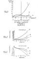
- the figure 3 represents the relation between the applied torque and the angle of rotation with respect to the position of the figure 2 .
- the torque corresponds to the tensile and flexural forces of the blades 4 due to the rotation of the rotor 3.
- the curve 7 corresponds to straight blades, that is to say a zero inclination angle ⁇ and makes it possible to compare the resistive torque in different cases of blade inclination. It can be seen that the torque increases asymptotically with the angle of rotation, since the components torque due to traction and bending add up. Curves 8 and 9 respectively correspond to angles of inclination ⁇ of 4 ° and 5 °. The torque remains low and stable in the rotation angle range considered, since in this case from a certain angle of rotation the traction component changes sign and retracts to the flexural component.
- the pivot 1 allows the rotation of the rotor 3 in a range of several degrees around a reference position, with a limited torque and stable, so without exceeding the capacity of the engine.
- 1.5 ° has been chosen as the reference position, and the rotor 3 can rotate in both directions from this position.
- the dashed lines 4 ' represent the position of the blades 4 when the rotor 3 is in the reference position.
- the Figures 7 and 8 represent the stresses present at the faces of the blades 4, as a function of the angle of rotation.
- the curves 15 and 18 correspond to straight blades, the curves 16 and 19 to an angle of inclination ⁇ of 4 °, and the curves 17 and 20 to an angle of inclination ⁇ of 5 °. Comparing the curves 15 and 18 to the others, it is found that the fact of providing a non-zero inclination angle ⁇ limits the constraints, which improves the mechanical strength and the life of the pivot 1.
- This optimal angle may depend on the dimensions of the pivot 1 and the material used.
- the optimum angle is in the range 2 ° to 10 °, preferably 4 ° to 5 °.
- the Figures 5 and 6 represent a support device 10 for rotary shaft 11, made with two pivots 1.
- the stators 2 of the pivots 1 are fixed to a frame 12, at a distance from each other with their axes A merged.
- the rotary shaft 11 is aligned with the axis A and is fixed to the two rotors 3.
- the forces exerted on the shaft 11, represented by the arrows 13, are resumed at the two pivots, as shown by FIG. arrows 14, which improves the mechanical strength of the device.
Landscapes
- Engineering & Computer Science (AREA)
- General Engineering & Computer Science (AREA)
- Mechanical Engineering (AREA)
- Remote Sensing (AREA)
- Aviation & Aerospace Engineering (AREA)
- Pivots And Pivotal Connections (AREA)
- Buildings Adapted To Withstand Abnormal External Influences (AREA)
- Springs (AREA)
- Flexible Shafts (AREA)
- Reciprocating, Oscillating Or Vibrating Motors (AREA)
- Structures Of Non-Positive Displacement Pumps (AREA)
- Scissors And Nippers (AREA)
- Carriages For Children, Sleds, And Other Hand-Operated Vehicles (AREA)
- Specific Sealing Or Ventilating Devices For Doors And Windows (AREA)
Description
- La présente invention se rapporte à un pivot traversant, c'est-à-dire un dispositif apte à supporter un arbre rotatif qui s'étant des deux côtés du pivot, et à un dispositif de support d'un arbre rotatif à amplitude de rotation limitée, réalisé avec ce pivot.
- Un pivot avec les caractéristiques du préambule de la revendication 1 est divulgué par le document
US 5,209,461 . - Dans les applications spatiales, il est nécessaire de pouvoir orienter certains éléments d'un satellite ou d'un véhicule spatial, tels qu'une antenne, un mât, etc., dans une direction prédéterminée afin, par exemple, de les diriger vers une étoile fixe, de conserver un pointage vers un point à la surface de la terre ou bien encore de balayer une zone particulière à la surface de la terre ou d'un astre quelconque. Ces positionnements doivent être fréquemment corrigés pour compenser d'inévitables dérives dans la tenue de cette direction et ces multiples corrections entraînent la réalisation d'un nombre important de cycles de micro-rotation pour ces appendices spatiaux et pour leurs dispositifs de support. Cette phase est appelée pointage fin.
- Compte tenu du caractère irréversible de la mise en orbite d'un satellite, il est nécessaire de prévoir lors de la conception de l'engin spatial, une durée de vie, mesurée en nombre de cycles, très importante pour ces dispositifs de support, de façon à garantir leur capacité à résister à ces très nombreuses sollicitations. Par exemple la durée de vie peut être supérieure à 600000 cycles. D'autres exigences des dispositifs de support sont une forte capacité de tenue mécanique (vis-à-vis des efforts extérieurs et moments de flexion exercés sur l'arbre supporté), une forte rigidité transverse, un guidage sans jeu de grande précision, une amplitude de rotation supérieure à 1° dans les deux sens, et un faible couple résistant.
- Il est connu de réaliser un dispositif de support pour un arbre rotatif avec un pivot à lames flexibles croisées, notamment ceux connus sous l'appellation « Pivot Bendix ». Ce type de pivot n'est pas traversant. Il est donc nécessaire de monter l'arbre supporté en porte-à-faux, ce qui implique des contraintes importantes dans les lames du pivot et une transmission de contraintes importantes au bâti support, même dans le cas d'un montage à double pivot. Ce type de pivot offre donc une tenue mécanique et une rigidité transverse limitée, et ne répond pas de manière satisfaisante à toutes les exigences pour la réalisation d'un dispositif de pointage fin.
- Il est également connu de supporter un arbre avec un dispositif comprenant deux pivots constitués de roulements à billes. Un tel dispositif est sujet à l'usure et présente donc une durée de vie limitée. Il ne répond donc pas non plus de manière satisfaisante à toutes les exigences pour la réalisation d'un dispositif de pointage fin destiné à une application spatiale.
- L'invention a pour but de proposer un pivot et un dispositif de support d'un arbre rotatif, qui ne présente pas au moins certains des inconvénients précités de l'art antérieur. En particulier, l'invention a pour but de proposer un pivot et un dispositif de support d'un arbre rotatif qui conviennent à la réalisation d'un dispositif de pointage fin, notamment pour une application spatiale.
- Pour cela, l'invention fournit un pivot traversant selon la revendication 1.
- Grâce à ces caractéristiques, le pivot peut supporter un arbre traversant, ce qui permet une bonne tenue mécanique. De plus, comme la rotation du rotor est autorisée par une déformation des éléments flexibles, il n'y a pas d'usure mécanique par frottement et la durée de vie est importante. On a constaté que l'agencement des éléments flexibles avec un angle d'inclinaison permettait de limiter les efforts de traction et de flexion dans les éléments flexibles. Le couple résistant et les contraintes dans les éléments flexibles sont donc faibles, ce qui permet un guidage de précision sur une amplitude de plusieurs degrés, et une durée de vie importante.
- De préférence, le stator comprend un cadre en forme de polygone régulier, les éléments flexibles étant fixés aux sommets respectifs du cadre.
- Avantageusement, le rotor comprend une bague cylindrique, les éléments flexibles étant fixés à une surface extérieure de ladite bague.
- Selon un mode de réalisation particulier, la bague présente un orifice central, le rotor étant apte à recevoir un arbre traversant passant par ledit orifice central.
- De préférence, le pivot comprend trois éléments flexibles répartis uniformément.
- Avantageusement, les éléments flexibles sont des lames qui présentent une forme plane rectangulaire et sont agencées dans un plan parallèle à l'axe de rotation. Cela permet de soutenir un effort axial.
- Selon un mode de réalisation particulier, l'angle d'inclinaison est compris entre 4° et 5°.
- L'invention fournit également un dispositif de support d'un arbre, comprenant deux pivots selon l'invention ci-dessus, agencés à distance l'un de l'autre avec leurs axes de rotation respectifs confondus.
- Cet agencement permet de mieux reprendre les efforts exercés sur l'arbre supporté, ce qui améliore la capacité de tenue mécanique et la rigidité. De plus, il est possible que l'arbre porte des éléments utiles des deux côtés du dispositif de support.
- L'invention sera mieux comprise, et d'autres buts, détails, caractéristiques et avantages de celle-ci apparaîtront plus clairement au cours de la description suivante d'un mode de réalisation particulier de l'invention, donné uniquement à titre illustratif et non limitatif, en référence aux dessins annexés. Sur ces dessins :
- la
figure 1 est une vue en perspective d'un pivot selon un mode de réalisation de l'invention, - la
figure 2 est une représentation schématique de la disposition des lames du pivot de lafigure 1 , - la
figure 3 est un graphe représentant la relation entre le couple appliqué et l'angle de rotation, pour le pivot de lafigure 1 , pour différents angles d'inclinaison, - la
figure 4 est une vue similaire à lafigure 2 , - la
figure 5 est un dispositif de support comprenant deux pivots du type de lafigure 1 , - la
figure 6 représente une vue en coupe du dispositif de lafigure 5 , - les
figures 7 et 8 sont des graphes représentant les contraintes dans les lames du pivot de lafigure 1 , en fonction de l'angle de rotation. - Le pivot 1 comprend un stator 2 comprenant un cadre en forme de triangle isocèle, et un rotor 3 apte à tourner par rapport au stator 2 autour d'un axe A. Le rotor 3 présente la forme d'une bague cylindrique de révolution, d'axe A. Les centres du stator 2 et du rotor 3 sont confondus.
- Le stator 2 et le rotor 3 sont reliés par trois lames 4. Les lames 4 présentent une forme de plaque rectangulaire plane. Elles sont reliées aux sommets respectifs du stator 2 par un petit côté, et à une surface extérieure du rotor 3 par le petit côté opposé.
- Le stator pourrait présenter une forme différente en fonction du mécanisme environnant, et notamment un nombre de côtés différent en fonction du nombre de lames, qui n'est pas nécessairement trois. De plus, les lames pourraient être remplacées par d'autres éléments flexibles, par exemples des tubes.
- La
figure 2 représente l'agencement des lames 4 de manière plus précise. Lafigure 2 représente la position des lames 4 quand le pivot 1 est dans un état de repos, c'est-à-dire quand aucun couple ne sollicite le rotor 3 en rotation. Les cercles d'implantation 5 et 6 présentent des diamètres correspondant aux positions respectives des petits côtés des lames 4. Les droites D correspondent à une direction radiale passant par l'axe A. On constate que les lames 4 forment un angle, appelé angle d'inclinaison α, par rapport à la direction radiale. - Le rotor 3 peut tourner dans le sens indiqué par la flèche 15 sur la
figure 4 , qui correspond au sens de l'angle d'inclinaison α. Sur lafigure 4 , les traits interrompus 4' représentent la position des lames 4 quand le rotor 3 a tourné de quelques degrés. Lafigure 3 représente la relation entre le couple appliqué et l'angle de rotation par rapport à la position de lafigure 2 . Le couple correspond aux efforts de traction et de flexion des lames 4 dus à la rotation du rotor 3. - La courbe 7 correspond à des lames droites, c'est-à-dire un angle d'inclinaison α nul et permet de comparer le couple résistant dans différents cas d'inclinaison de lame. On constate que le couple augmente de manière asymptotique avec l'angle de rotation, car les composantes du couple dues à la traction et à la flexion s'additionnent. Les courbes 8 et 9 correspondent respectivement à des angles d'inclinaison α de 4° et 5°. Le couple reste faible et stable dans la plage d'angle de rotation considérée, car dans ce cas à partir d'un certain angle de rotation la composante de traction change de signe et se retranche à la composante de flexion.
- On constate donc que le pivot 1 permet la rotation du rotor 3 dans une plage de plusieurs degrés autour d'une position de référence, avec un couple limité et stable, donc sans dépasser la capacité du moteur. Dans l'exemple représenté, on a choisi 1,5° comme position de référence, et le rotor 3 peut tourner dans les deux sens à partir de cette position. Sur la
figure 4 , les traits interrompus 4' représentent la position des lames 4 quand le rotor 3 est dans la position de référence. - Les
figures 7 et 8 représentent les contraintes présentes au niveau des faces des lames 4, en fonction de l'angle de rotation. Les courbes 15 et 18 correspondent à des lames droites, les courbes 16 et 19 à un angle d'inclinaison α de 4°, et les courbes 17 et 20 à un angle d'inclinaison α de 5°. En comparant les courbes 15 et 18 aux autres, on constate que le fait de prévoir un angle d'inclinaison α non nul permet de limiter les contraintes, ce qui améliore la tenue mécanique et la durée de vie du pivot 1. - Il existe un angle d'inclinaison α optimal qui permet de minimiser le couple et/ou les contraintes. Cet angle optimal peut dépendre des dimensions du pivot 1 et du matériau utilisé. L'angle optimal est compris dans la plage 2° à 10°, de préférence 4° à 5°.
- Les
figures 5 et 6 représentent un dispositif de support 10 pour arbre rotatif 11, réalisé avec deux pivots 1. Les stators 2 des pivots 1 sont fixés à un bâti 12, à distance l'un de l'autre avec leurs axes A confondus. L'arbre rotatif 11 est aligné avec l'axe A et est fixé aux deux rotors 3. Dans ce dispositif, les efforts exercés sur l'arbre 11, représentés par les flèches 13, sont repris au niveau des deux pivots, comme le montrent les flèches 14, ce qui améliore la tenue mécanique du dispositif.
Claims (8)
- Pivot (1) traversant comprenant un stator (2) et un rotor (3) apte à tourner par rapport au stator autour d'un axe de rotation (A), le rotor étant apte à recevoir un arbre traversant (11) aligné avec ledit axe de rotation, le rotor étant relié au stator par une pluralité d'éléments flexibles (4) aptes à se déformer pour permettre la rotation du rotor, caractérisé par le fait que dans un état de repos, les éléments flexibles forment un angle d'inclinaison (α) par rapport à une direction radiale (D) passant par l'axe de rotation, compris entre 2° et 10°.
- Pivot selon la revendication 1, dans lequel le stator comprend un cadre en forme de polygone régulier, les éléments flexibles étant fixés aux sommets respectifs du cadre.
- Pivot selon l'une des revendications 1 à 2, dans lequel le rotor comprend une bague cylindrique, les éléments flexibles étant fixés à une surface extérieure de ladite bague.
- Pivot selon la revendication 3, dans lequel la bague présente un orifice central apte à recevoir un arbre traversant passant par ledit orifice central.
- Pivot selon l'une des revendications 1 à 4, comprenant trois éléments flexibles répartis uniformément.
- Pivot selon l'une des revendications 1 à 5, dans lequel les éléments flexibles sont des lames qui présentent une forme plane rectangulaire et sont agencées dans un plan parallèle à l'axe de rotation.
- Pivot selon la revendication 1, dans lequel l'angle d'inclinaison est compris entre 4° et 5°.
- Dispositif de support (10) d'un arbre (11), comprenant deux pivots (1) selon l'une des revendications 1 à 7 agencés à distance l'un de l'autre avec leurs axes de rotation (A) respectifs confondus.
Applications Claiming Priority (1)
| Application Number | Priority Date | Filing Date | Title |
|---|---|---|---|
| FR0753521A FR2913078B1 (fr) | 2007-02-27 | 2007-02-27 | Pivot traversant a lames. |
Publications (2)
| Publication Number | Publication Date |
|---|---|
| EP1964778A1 EP1964778A1 (fr) | 2008-09-03 |
| EP1964778B1 true EP1964778B1 (fr) | 2010-04-07 |
Family
ID=38511822
Family Applications (1)
| Application Number | Title | Priority Date | Filing Date |
|---|---|---|---|
| EP08102032A Active EP1964778B1 (fr) | 2007-02-27 | 2008-02-26 | Pivot traversant à lames |
Country Status (8)
| Country | Link |
|---|---|
| US (1) | US8734043B2 (fr) |
| EP (1) | EP1964778B1 (fr) |
| JP (1) | JP5732689B2 (fr) |
| CN (1) | CN101275607B (fr) |
| AT (1) | ATE463421T1 (fr) |
| DE (1) | DE602008000916D1 (fr) |
| ES (1) | ES2341394T3 (fr) |
| FR (1) | FR2913078B1 (fr) |
Cited By (1)
| Publication number | Priority date | Publication date | Assignee | Title |
|---|---|---|---|---|
| US11085565B2 (en) | 2017-01-13 | 2021-08-10 | Unison Industries, Llc | Gimbaled flexure for spherical flex joints |
Families Citing this family (6)
| Publication number | Priority date | Publication date | Assignee | Title |
|---|---|---|---|---|
| FR2945848B1 (fr) * | 2009-05-19 | 2012-01-13 | Thales Sa | Pivot traversant a elements flexibles et engin spatial comportant un tel pivot |
| FR3001267B1 (fr) * | 2013-01-18 | 2015-08-21 | Thales Sa | Element de suspension pour la liaison mecanique d'une charge suspendue dans un support |
| US10030731B1 (en) * | 2013-03-13 | 2018-07-24 | Hrl Laboratories, Llc | Assembly with negative torsional stiffness |
| CN103698389B (zh) * | 2014-01-15 | 2016-04-20 | 爱德森(厦门)电子有限公司 | 一种使被检件始终沿着外穿式探头中轴线运行的方法 |
| EP3165470A1 (fr) * | 2015-11-06 | 2017-05-10 | Almatech Sarl | Pivot flexible à grand angle |
| EP3476748B1 (fr) * | 2017-10-24 | 2020-07-15 | CSEM Centre Suisse d'Electronique et de Microtechnique SA - Recherche et Développement | Mécanisme pivot à éléments flexibles |
Family Cites Families (47)
| Publication number | Priority date | Publication date | Assignee | Title |
|---|---|---|---|---|
| US2465425A (en) * | 1944-07-24 | 1949-03-29 | Fairbanks Morse & Co | Intermediate bearing retainer for deep well pumps |
| US2621850A (en) * | 1947-08-01 | 1952-12-16 | Dodge Mfg Corp | Means for mounting fan shafts of blowers |
| US2722464A (en) * | 1952-04-30 | 1955-11-01 | Morrison Products Inc | Self-aligning bearing |
| US2936999A (en) * | 1956-12-07 | 1960-05-17 | United Aircraft Corp | Tangential bearing supports |
| US3083757A (en) * | 1960-11-15 | 1963-04-02 | Phillips Petroleum Co | Knife sealer for thermoplastic film or sheet |
| CH399090A (de) * | 1962-01-17 | 1966-03-31 | Escher Wyss Ag | Einrichtung zur nachgiebigen Aufhängung der Lagerbüchse eines Radiallagers |
| US3318642A (en) * | 1963-10-17 | 1967-05-09 | Bunting Brass & Bronze Co | Self-aligning bearing |
| US3343013A (en) * | 1964-12-10 | 1967-09-19 | Emerson Electric Co | End shield assembly |
| US3400939A (en) * | 1966-01-03 | 1968-09-10 | Curtiss Wright Corp | Oil seal construction for rotary engines |
| GB1137245A (en) * | 1966-11-16 | 1968-12-18 | Stal Laval Turbin Aktibolag | Method of mounting bearings for counter-rotating shafts and a bearing mounted in accordance therewith |
| US3509578A (en) * | 1967-06-21 | 1970-04-28 | Nasa | Weatherproof helix antenna |
| US3648999A (en) * | 1969-12-19 | 1972-03-14 | Westinghouse Electric Corp | Suspension spring |
| US3664185A (en) * | 1970-06-04 | 1972-05-23 | Nasa | Rotary actuator |
| DE2264050B2 (de) * | 1972-12-29 | 1979-12-06 | Siemens Ag, 1000 Berlin Und 8000 Muenchen | Federgelagerter Hebel |
| DE2653427C3 (de) * | 1976-11-24 | 1979-05-03 | Anschuetz & Co Gmbh, 2300 Kiel | Federgelenk zur schwenkbaren Verbindung zweier Körper miteinander u. Verfahren zur Herstellung des Gelenks |
| DE2744697A1 (de) * | 1977-10-05 | 1979-04-12 | Babcock Ag | Unterstuetzungsbock |
| DE3509128C1 (de) * | 1985-03-14 | 1986-10-02 | Jean Walterscheid Gmbh, 5204 Lohmar | Lagerring |
| US5545118A (en) * | 1989-08-02 | 1996-08-13 | Romanauskas; William A. | Tension band centrifuge rotor |
| DE4010041A1 (de) * | 1990-03-29 | 1991-10-02 | Erno Raumfahrttechnik Gmbh | Spiel- und reibungsfreies universalgelenk |
| US5209461A (en) * | 1990-07-23 | 1993-05-11 | Ltv Energy Products Company | Elastomeric torsional spring having tangential spokes with varying elastic response |
| DE4228170C2 (de) * | 1992-08-25 | 1995-06-29 | Freudenberg Carl Fa | Lager |
| US5475275A (en) * | 1994-02-10 | 1995-12-12 | Emerson Electric Co. | Motor assemblies with improved endshields |
| US5610461A (en) * | 1994-02-14 | 1997-03-11 | Emerson Electric Co. | Motor endshields |
| DE4447610C2 (de) * | 1994-09-06 | 1997-06-12 | Clouth Gummiwerke Ag | Schwingungstilger |
| US5620169A (en) * | 1994-11-02 | 1997-04-15 | Ball Corporation | Rotary mount integral flexural pivot with blades which are integrally interconnected at the blade intersection |
| JPH1014157A (ja) * | 1996-06-19 | 1998-01-16 | Mitsubishi Electric Corp | 電動送風機 |
| US6146044A (en) * | 1997-09-02 | 2000-11-14 | California Institute Of Technology | Rotary flexure |
| FR2781264B1 (fr) * | 1998-07-20 | 2000-09-01 | Suisse Electronique Microtech | Pivot flexible a axe interieur de pivotement |
| US6440044B1 (en) * | 1998-08-07 | 2002-08-27 | Spiraflex, Inc. | Resistance mechanism with series connected resistance packs |
| US6200220B1 (en) * | 1998-11-05 | 2001-03-13 | Chester Drew | Flexible vane coupling |
| US6508630B2 (en) * | 2001-03-30 | 2003-01-21 | General Electric Company | Twisted stator vane |
| US6911757B2 (en) * | 2001-08-10 | 2005-06-28 | Rotys Inc. | Ring stator motor device |
| US7093827B2 (en) * | 2001-11-08 | 2006-08-22 | Massachusetts Institute Of Technology | Multiple degree of freedom compliant mechanism |
| EP1420179B1 (fr) * | 2002-11-13 | 2007-01-10 | Contraves Space AG | Dispositif de suspension du type à flexion à trois degrés de liberté et dispositif de positionnement l'utilisant |
| US7011504B2 (en) * | 2003-04-04 | 2006-03-14 | Nidec America Corporation | Fan, fan guard and related method |
| TWM242999U (en) * | 2003-09-08 | 2004-09-01 | Enermax Technology Corp | Heat dissipation fan with built-in adjustable rotational speed |
| TWM245812U (en) * | 2003-11-21 | 2004-10-11 | Quarton Inc | Positionable rotary seat |
| DE602004024052D1 (de) * | 2004-07-20 | 2009-12-24 | Varian Spa | Ringförmiger Laufstützkörper für Wälzlagern |
| US7364145B2 (en) * | 2004-09-08 | 2008-04-29 | Equipment Solutions, Inc | High stiffness flexure |
| EP1722462B1 (fr) * | 2005-05-10 | 2008-11-05 | Siemens Aktiengesellschaft | Machine électrique |
| WO2007038140A2 (fr) * | 2005-09-21 | 2007-04-05 | Delaware Capital Formation, Inc. | Ressort de soupape elastomere de compresseur a piston |
| FR2891301B1 (fr) * | 2005-09-29 | 2007-11-02 | Snecma Sa | Carter structural de turbomoteur |
| DE102005058661B4 (de) * | 2005-12-07 | 2018-11-29 | Deutsches Zentrum für Luft- und Raumfahrt e.V. | Kupplung zum Ausgleichen eines Achsversatzes |
| TWI326333B (en) * | 2006-12-26 | 2010-06-21 | Sunonwealth Electr Mach Ind Co | Low air-noise fan housing structure |
| US20080170935A1 (en) * | 2007-01-16 | 2008-07-17 | Sanyo Denki Co., Ltd. | Axial-flow fan |
| US8176809B2 (en) * | 2008-12-10 | 2012-05-15 | GM Global Technology Operations LLC | Planar torsion spring |
| FR2945848B1 (fr) * | 2009-05-19 | 2012-01-13 | Thales Sa | Pivot traversant a elements flexibles et engin spatial comportant un tel pivot |
-
2007
- 2007-02-27 FR FR0753521A patent/FR2913078B1/fr not_active Expired - Fee Related
-
2008
- 2008-02-25 JP JP2008043231A patent/JP5732689B2/ja not_active Expired - Fee Related
- 2008-02-26 AT AT08102032T patent/ATE463421T1/de active
- 2008-02-26 EP EP08102032A patent/EP1964778B1/fr active Active
- 2008-02-26 ES ES08102032T patent/ES2341394T3/es active Active
- 2008-02-26 DE DE602008000916T patent/DE602008000916D1/de active Active
- 2008-02-27 US US12/038,069 patent/US8734043B2/en active Active
- 2008-02-27 CN CN2008100881282A patent/CN101275607B/zh not_active Expired - Fee Related
Cited By (2)
| Publication number | Priority date | Publication date | Assignee | Title |
|---|---|---|---|---|
| US11085565B2 (en) | 2017-01-13 | 2021-08-10 | Unison Industries, Llc | Gimbaled flexure for spherical flex joints |
| US11754210B2 (en) | 2017-01-13 | 2023-09-12 | General Electric Company | Gimbaled flexure for spherical flex joints |
Also Published As
| Publication number | Publication date |
|---|---|
| ES2341394T3 (es) | 2010-06-18 |
| US8734043B2 (en) | 2014-05-27 |
| FR2913078A1 (fr) | 2008-08-29 |
| FR2913078B1 (fr) | 2009-11-20 |
| CN101275607B (zh) | 2012-03-07 |
| EP1964778A1 (fr) | 2008-09-03 |
| US20080205976A1 (en) | 2008-08-28 |
| CN101275607A (zh) | 2008-10-01 |
| JP5732689B2 (ja) | 2015-06-10 |
| DE602008000916D1 (de) | 2010-05-20 |
| JP2008209001A (ja) | 2008-09-11 |
| ATE463421T1 (de) | 2010-04-15 |
Similar Documents
| Publication | Publication Date | Title |
|---|---|---|
| EP1964778B1 (fr) | Pivot traversant à lames | |
| EP2256039B1 (fr) | Pivot traversant à éléments flexibles et engin spatial comportant un tel pivot | |
| EP2630379B1 (fr) | Cardan flexible compact et engin spatial comportant un tel cardan | |
| EP2598722B1 (fr) | Dispositif de commande d'aubes pivotantes de turbomachine | |
| FR3017163A1 (fr) | Dispositif pour une helice non carenee a pales a calage variable d'une turbomachine | |
| EP0537446B1 (fr) | Moteur piézo-électrique | |
| EP3309625A1 (fr) | Spiral destiné à être fixé par une rondelle élastique | |
| EP1491725A2 (fr) | Dispositif de guidage d'une aube à angle de calage variable | |
| EP3947158B1 (fr) | Dispositif de déploiement et de pointage d'un équipement porté par un engin spatial | |
| FR2914944A1 (fr) | Calage variable d'aubes de compresseur dans une turbomachine | |
| FR2760102A1 (fr) | Autodirecteur orientable | |
| EP0465280A1 (fr) | Dispositif d'accouplement en rotation de grande précision et dispositif de commande en translation le comportant, notamment pour instrument optique spatial | |
| EP2837557B1 (fr) | Dispositif de couplage d'une roue motorisée de train d'atterrissage d'aéronef | |
| EP2733340B1 (fr) | Tige filetée d'un système de déploiement d'un divergent déployable de propulseur | |
| EP2333365A1 (fr) | Entretoises à longueurs ajustées pour roulements | |
| EP0455543B1 (fr) | Dispositif de pointage d'un réflecteur d'antenne | |
| EP1564381B1 (fr) | Levier de commande du calage angulaire d'une aube dans une turbomachine | |
| EP3839604B1 (fr) | Dispositif de scan à excentrique amélioré | |
| EP3947160B1 (fr) | Satellite géostationnaire comprenant un radiateur à ensoleillement réduit et système de guidage amélioré | |
| EP0463950B1 (fr) | Dispositif de déplacement d'un organe et application au pointage d'un réflecteur d'antenne | |
| WO2018086918A1 (fr) | Dispositif de transmission mecanique | |
| FR2821397A1 (fr) | Dispositif d'articulation et de commande en orientation pour volet aerodynamique | |
| WO2025228922A1 (fr) | Atterrisseur d'aeronef equipe d'un dispositif de verrouillage a ressort a lame | |
| FR3054933A1 (fr) | Positionneur pour antenne | |
| FR3096747A1 (fr) | Palier lisse, compas de rotor de giravion et rotor associe |
Legal Events
| Date | Code | Title | Description |
|---|---|---|---|
| PUAI | Public reference made under article 153(3) epc to a published international application that has entered the european phase |
Free format text: ORIGINAL CODE: 0009012 |
|
| AK | Designated contracting states |
Kind code of ref document: A1 Designated state(s): AT BE BG CH CY CZ DE DK EE ES FI FR GB GR HR HU IE IS IT LI LT LU LV MC MT NL NO PL PT RO SE SI SK TR |
|
| AX | Request for extension of the european patent |
Extension state: AL BA MK RS |
|
| 17P | Request for examination filed |
Effective date: 20090213 |
|
| AKX | Designation fees paid |
Designated state(s): AT BE BG CH CY CZ DE DK EE ES FI FR GB GR HR HU IE IS IT LI LT LU LV MC MT NL NO PL PT RO SE SI SK TR |
|
| GRAP | Despatch of communication of intention to grant a patent |
Free format text: ORIGINAL CODE: EPIDOSNIGR1 |
|
| GRAS | Grant fee paid |
Free format text: ORIGINAL CODE: EPIDOSNIGR3 |
|
| GRAA | (expected) grant |
Free format text: ORIGINAL CODE: 0009210 |
|
| AK | Designated contracting states |
Kind code of ref document: B1 Designated state(s): AT BE BG CH CY CZ DE DK EE ES FI FR GB GR HR HU IE IS IT LI LT LU LV MC MT NL NO PL PT RO SE SI SK TR |
|
| REG | Reference to a national code |
Ref country code: GB Ref legal event code: FG4D Free format text: NOT ENGLISH |
|
| REG | Reference to a national code |
Ref country code: CH Ref legal event code: EP |
|
| REG | Reference to a national code |
Ref country code: IE Ref legal event code: FG4D Free format text: LANGUAGE OF EP DOCUMENT: FRENCH |
|
| REG | Reference to a national code |
Ref country code: CH Ref legal event code: NV Representative=s name: SERVOPATENT GMBH |
|
| REF | Corresponds to: |
Ref document number: 602008000916 Country of ref document: DE Date of ref document: 20100520 Kind code of ref document: P |
|
| REG | Reference to a national code |
Ref country code: NL Ref legal event code: T3 |
|
| REG | Reference to a national code |
Ref country code: ES Ref legal event code: FG2A Ref document number: 2341394 Country of ref document: ES Kind code of ref document: T3 |
|
| REG | Reference to a national code |
Ref country code: SE Ref legal event code: TRGR |
|
| PG25 | Lapsed in a contracting state [announced via postgrant information from national office to epo] |
Ref country code: SI Free format text: LAPSE BECAUSE OF FAILURE TO SUBMIT A TRANSLATION OF THE DESCRIPTION OR TO PAY THE FEE WITHIN THE PRESCRIBED TIME-LIMIT Effective date: 20100407 |
|
| LTIE | Lt: invalidation of european patent or patent extension |
Effective date: 20100407 |
|
| REG | Reference to a national code |
Ref country code: IE Ref legal event code: FD4D |
|
| PG25 | Lapsed in a contracting state [announced via postgrant information from national office to epo] |
Ref country code: LT Free format text: LAPSE BECAUSE OF FAILURE TO SUBMIT A TRANSLATION OF THE DESCRIPTION OR TO PAY THE FEE WITHIN THE PRESCRIBED TIME-LIMIT Effective date: 20100407 Ref country code: NO Free format text: LAPSE BECAUSE OF FAILURE TO SUBMIT A TRANSLATION OF THE DESCRIPTION OR TO PAY THE FEE WITHIN THE PRESCRIBED TIME-LIMIT Effective date: 20100707 |
|
| PG25 | Lapsed in a contracting state [announced via postgrant information from national office to epo] |
Ref country code: FI Free format text: LAPSE BECAUSE OF FAILURE TO SUBMIT A TRANSLATION OF THE DESCRIPTION OR TO PAY THE FEE WITHIN THE PRESCRIBED TIME-LIMIT Effective date: 20100407 Ref country code: HR Free format text: LAPSE BECAUSE OF FAILURE TO SUBMIT A TRANSLATION OF THE DESCRIPTION OR TO PAY THE FEE WITHIN THE PRESCRIBED TIME-LIMIT Effective date: 20100407 Ref country code: IS Free format text: LAPSE BECAUSE OF FAILURE TO SUBMIT A TRANSLATION OF THE DESCRIPTION OR TO PAY THE FEE WITHIN THE PRESCRIBED TIME-LIMIT Effective date: 20100807 Ref country code: LV Free format text: LAPSE BECAUSE OF FAILURE TO SUBMIT A TRANSLATION OF THE DESCRIPTION OR TO PAY THE FEE WITHIN THE PRESCRIBED TIME-LIMIT Effective date: 20100407 |
|
| PG25 | Lapsed in a contracting state [announced via postgrant information from national office to epo] |
Ref country code: PL Free format text: LAPSE BECAUSE OF FAILURE TO SUBMIT A TRANSLATION OF THE DESCRIPTION OR TO PAY THE FEE WITHIN THE PRESCRIBED TIME-LIMIT Effective date: 20100407 Ref country code: CY Free format text: LAPSE BECAUSE OF FAILURE TO SUBMIT A TRANSLATION OF THE DESCRIPTION OR TO PAY THE FEE WITHIN THE PRESCRIBED TIME-LIMIT Effective date: 20100602 |
|
| PG25 | Lapsed in a contracting state [announced via postgrant information from national office to epo] |
Ref country code: DK Free format text: LAPSE BECAUSE OF FAILURE TO SUBMIT A TRANSLATION OF THE DESCRIPTION OR TO PAY THE FEE WITHIN THE PRESCRIBED TIME-LIMIT Effective date: 20100407 Ref country code: EE Free format text: LAPSE BECAUSE OF FAILURE TO SUBMIT A TRANSLATION OF THE DESCRIPTION OR TO PAY THE FEE WITHIN THE PRESCRIBED TIME-LIMIT Effective date: 20100407 Ref country code: IE Free format text: LAPSE BECAUSE OF FAILURE TO SUBMIT A TRANSLATION OF THE DESCRIPTION OR TO PAY THE FEE WITHIN THE PRESCRIBED TIME-LIMIT Effective date: 20100407 |
|
| PLBE | No opposition filed within time limit |
Free format text: ORIGINAL CODE: 0009261 |
|
| STAA | Information on the status of an ep patent application or granted ep patent |
Free format text: STATUS: NO OPPOSITION FILED WITHIN TIME LIMIT |
|
| PG25 | Lapsed in a contracting state [announced via postgrant information from national office to epo] |
Ref country code: RO Free format text: LAPSE BECAUSE OF FAILURE TO SUBMIT A TRANSLATION OF THE DESCRIPTION OR TO PAY THE FEE WITHIN THE PRESCRIBED TIME-LIMIT Effective date: 20100407 Ref country code: SK Free format text: LAPSE BECAUSE OF FAILURE TO SUBMIT A TRANSLATION OF THE DESCRIPTION OR TO PAY THE FEE WITHIN THE PRESCRIBED TIME-LIMIT Effective date: 20100407 Ref country code: CZ Free format text: LAPSE BECAUSE OF FAILURE TO SUBMIT A TRANSLATION OF THE DESCRIPTION OR TO PAY THE FEE WITHIN THE PRESCRIBED TIME-LIMIT Effective date: 20100407 |
|
| 26N | No opposition filed |
Effective date: 20110110 |
|
| PG25 | Lapsed in a contracting state [announced via postgrant information from national office to epo] |
Ref country code: GR Free format text: LAPSE BECAUSE OF FAILURE TO SUBMIT A TRANSLATION OF THE DESCRIPTION OR TO PAY THE FEE WITHIN THE PRESCRIBED TIME-LIMIT Effective date: 20100708 |
|
| BERE | Be: lapsed |
Owner name: THALES Effective date: 20110228 |
|
| PG25 | Lapsed in a contracting state [announced via postgrant information from national office to epo] |
Ref country code: MC Free format text: LAPSE BECAUSE OF NON-PAYMENT OF DUE FEES Effective date: 20110228 |
|
| PG25 | Lapsed in a contracting state [announced via postgrant information from national office to epo] |
Ref country code: BE Free format text: LAPSE BECAUSE OF NON-PAYMENT OF DUE FEES Effective date: 20110228 |
|
| PG25 | Lapsed in a contracting state [announced via postgrant information from national office to epo] |
Ref country code: MT Free format text: LAPSE BECAUSE OF FAILURE TO SUBMIT A TRANSLATION OF THE DESCRIPTION OR TO PAY THE FEE WITHIN THE PRESCRIBED TIME-LIMIT Effective date: 20100407 |
|
| PG25 | Lapsed in a contracting state [announced via postgrant information from national office to epo] |
Ref country code: LU Free format text: LAPSE BECAUSE OF NON-PAYMENT OF DUE FEES Effective date: 20110226 |
|
| PG25 | Lapsed in a contracting state [announced via postgrant information from national office to epo] |
Ref country code: PT Free format text: LAPSE BECAUSE OF NON-PAYMENT OF DUE FEES Effective date: 20100407 |
|
| PG25 | Lapsed in a contracting state [announced via postgrant information from national office to epo] |
Ref country code: TR Free format text: LAPSE BECAUSE OF FAILURE TO SUBMIT A TRANSLATION OF THE DESCRIPTION OR TO PAY THE FEE WITHIN THE PRESCRIBED TIME-LIMIT Effective date: 20100407 Ref country code: BG Free format text: LAPSE BECAUSE OF FAILURE TO SUBMIT A TRANSLATION OF THE DESCRIPTION OR TO PAY THE FEE WITHIN THE PRESCRIBED TIME-LIMIT Effective date: 20100707 |
|
| PG25 | Lapsed in a contracting state [announced via postgrant information from national office to epo] |
Ref country code: HU Free format text: LAPSE BECAUSE OF FAILURE TO SUBMIT A TRANSLATION OF THE DESCRIPTION OR TO PAY THE FEE WITHIN THE PRESCRIBED TIME-LIMIT Effective date: 20100407 |
|
| REG | Reference to a national code |
Ref country code: FR Ref legal event code: PLFP Year of fee payment: 9 |
|
| REG | Reference to a national code |
Ref country code: FR Ref legal event code: PLFP Year of fee payment: 10 |
|
| REG | Reference to a national code |
Ref country code: FR Ref legal event code: PLFP Year of fee payment: 11 |
|
| PGFP | Annual fee paid to national office [announced via postgrant information from national office to epo] |
Ref country code: NL Payment date: 20190214 Year of fee payment: 12 |
|
| PGFP | Annual fee paid to national office [announced via postgrant information from national office to epo] |
Ref country code: PL Payment date: 20190312 Year of fee payment: 12 Ref country code: DE Payment date: 20190212 Year of fee payment: 12 Ref country code: IT Payment date: 20190221 Year of fee payment: 12 |
|
| PGFP | Annual fee paid to national office [announced via postgrant information from national office to epo] |
Ref country code: SE Payment date: 20190212 Year of fee payment: 12 Ref country code: AT Payment date: 20190125 Year of fee payment: 12 |
|
| REG | Reference to a national code |
Ref country code: CH Ref legal event code: PCAR Free format text: NEW ADDRESS: WANNERSTRASSE 9/1, 8045 ZUERICH (CH) |
|
| REG | Reference to a national code |
Ref country code: DE Ref legal event code: R119 Ref document number: 602008000916 Country of ref document: DE |
|
| REG | Reference to a national code |
Ref country code: SE Ref legal event code: EUG |
|
| REG | Reference to a national code |
Ref country code: NL Ref legal event code: MM Effective date: 20200301 |
|
| REG | Reference to a national code |
Ref country code: AT Ref legal event code: MM01 Ref document number: 463421 Country of ref document: AT Kind code of ref document: T Effective date: 20200226 |
|
| PG25 | Lapsed in a contracting state [announced via postgrant information from national office to epo] |
Ref country code: SE Free format text: LAPSE BECAUSE OF NON-PAYMENT OF DUE FEES Effective date: 20200227 |
|
| PG25 | Lapsed in a contracting state [announced via postgrant information from national office to epo] |
Ref country code: AT Free format text: LAPSE BECAUSE OF NON-PAYMENT OF DUE FEES Effective date: 20200226 |
|
| PG25 | Lapsed in a contracting state [announced via postgrant information from national office to epo] |
Ref country code: NL Free format text: LAPSE BECAUSE OF NON-PAYMENT OF DUE FEES Effective date: 20200301 |
|
| PG25 | Lapsed in a contracting state [announced via postgrant information from national office to epo] |
Ref country code: DE Free format text: LAPSE BECAUSE OF NON-PAYMENT OF DUE FEES Effective date: 20200901 |
|
| REG | Reference to a national code |
Ref country code: ES Ref legal event code: FD2A Effective date: 20210708 |
|
| PG25 | Lapsed in a contracting state [announced via postgrant information from national office to epo] |
Ref country code: IT Free format text: LAPSE BECAUSE OF NON-PAYMENT OF DUE FEES Effective date: 20200226 |
|
| PG25 | Lapsed in a contracting state [announced via postgrant information from national office to epo] |
Ref country code: ES Free format text: LAPSE BECAUSE OF NON-PAYMENT OF DUE FEES Effective date: 20200227 |
|
| PGFP | Annual fee paid to national office [announced via postgrant information from national office to epo] |
Ref country code: CH Payment date: 20250301 Year of fee payment: 18 |
|
| PGFP | Annual fee paid to national office [announced via postgrant information from national office to epo] |
Ref country code: FR Payment date: 20250121 Year of fee payment: 18 |
|
| PGFP | Annual fee paid to national office [announced via postgrant information from national office to epo] |
Ref country code: GB Payment date: 20250116 Year of fee payment: 18 |