EP1964706A1 - Charge air hose - Google Patents
Charge air hose Download PDFInfo
- Publication number
- EP1964706A1 EP1964706A1 EP07024832A EP07024832A EP1964706A1 EP 1964706 A1 EP1964706 A1 EP 1964706A1 EP 07024832 A EP07024832 A EP 07024832A EP 07024832 A EP07024832 A EP 07024832A EP 1964706 A1 EP1964706 A1 EP 1964706A1
- Authority
- EP
- European Patent Office
- Prior art keywords
- charge air
- hose
- air hose
- elastomer
- print carrier
- Prior art date
- Legal status (The legal status is an assumption and is not a legal conclusion. Google has not performed a legal analysis and makes no representation as to the accuracy of the status listed.)
- Withdrawn
Links
- 239000004753 textile Substances 0.000 claims abstract description 103
- 229920001971 elastomer Polymers 0.000 claims abstract description 66
- 239000000806 elastomer Substances 0.000 claims abstract description 66
- 238000004519 manufacturing process Methods 0.000 claims abstract description 10
- 239000000463 material Substances 0.000 claims description 33
- 239000011248 coating agent Substances 0.000 claims description 30
- 238000000576 coating method Methods 0.000 claims description 30
- 238000009954 braiding Methods 0.000 claims description 13
- 238000000034 method Methods 0.000 claims description 12
- 238000005470 impregnation Methods 0.000 claims description 11
- 239000011521 glass Substances 0.000 claims description 9
- 238000001125 extrusion Methods 0.000 claims description 4
- 229920005989 resin Polymers 0.000 claims description 4
- 239000011347 resin Substances 0.000 claims description 4
- 229920002379 silicone rubber Polymers 0.000 claims description 4
- 229920002725 thermoplastic elastomer Polymers 0.000 claims description 4
- 238000007598 dipping method Methods 0.000 claims description 3
- 238000001746 injection moulding Methods 0.000 claims description 3
- 238000010422 painting Methods 0.000 claims description 3
- 238000005538 encapsulation Methods 0.000 claims description 2
- 230000002787 reinforcement Effects 0.000 abstract 1
- 239000000758 substrate Substances 0.000 description 29
- 238000007639 printing Methods 0.000 description 27
- 239000011159 matrix material Substances 0.000 description 5
- 230000008569 process Effects 0.000 description 4
- 230000005540 biological transmission Effects 0.000 description 2
- 238000010276 construction Methods 0.000 description 2
- 230000008878 coupling Effects 0.000 description 2
- 238000010168 coupling process Methods 0.000 description 2
- 238000005859 coupling reaction Methods 0.000 description 2
- 230000032798 delamination Effects 0.000 description 2
- 230000000694 effects Effects 0.000 description 2
- 239000013536 elastomeric material Substances 0.000 description 2
- 238000005516 engineering process Methods 0.000 description 2
- 239000004744 fabric Substances 0.000 description 2
- 230000010354 integration Effects 0.000 description 2
- 238000009940 knitting Methods 0.000 description 2
- 238000000465 moulding Methods 0.000 description 2
- 230000006978 adaptation Effects 0.000 description 1
- 238000004026 adhesive bonding Methods 0.000 description 1
- 230000008901 benefit Effects 0.000 description 1
- 239000000969 carrier Substances 0.000 description 1
- 239000002131 composite material Substances 0.000 description 1
- 238000004132 cross linking Methods 0.000 description 1
- 238000007667 floating Methods 0.000 description 1
- 239000003365 glass fiber Substances 0.000 description 1
- 238000009434 installation Methods 0.000 description 1
- 230000003993 interaction Effects 0.000 description 1
- 238000002372 labelling Methods 0.000 description 1
- 239000002184 metal Substances 0.000 description 1
- 230000000149 penetrating effect Effects 0.000 description 1
- 239000004033 plastic Substances 0.000 description 1
- 230000001681 protective effect Effects 0.000 description 1
- 239000000243 solution Substances 0.000 description 1
- 239000000126 substance Substances 0.000 description 1
Images


Classifications
-
- F—MECHANICAL ENGINEERING; LIGHTING; HEATING; WEAPONS; BLASTING
- F02—COMBUSTION ENGINES; HOT-GAS OR COMBUSTION-PRODUCT ENGINE PLANTS
- F02M—SUPPLYING COMBUSTION ENGINES IN GENERAL WITH COMBUSTIBLE MIXTURES OR CONSTITUENTS THEREOF
- F02M35/00—Combustion-air cleaners, air intakes, intake silencers, or induction systems specially adapted for, or arranged on, internal-combustion engines
- F02M35/10—Air intakes; Induction systems
- F02M35/10091—Air intakes; Induction systems characterised by details of intake ducts: shapes; connections; arrangements
- F02M35/10137—Flexible ducts, e.g. bellows or hoses
-
- F—MECHANICAL ENGINEERING; LIGHTING; HEATING; WEAPONS; BLASTING
- F02—COMBUSTION ENGINES; HOT-GAS OR COMBUSTION-PRODUCT ENGINE PLANTS
- F02M—SUPPLYING COMBUSTION ENGINES IN GENERAL WITH COMBUSTIBLE MIXTURES OR CONSTITUENTS THEREOF
- F02M35/00—Combustion-air cleaners, air intakes, intake silencers, or induction systems specially adapted for, or arranged on, internal-combustion engines
- F02M35/10—Air intakes; Induction systems
- F02M35/10006—Air intakes; Induction systems characterised by the position of elements of the air intake system in direction of the air intake flow, i.e. between ambient air inlet and supply to the combustion chamber
- F02M35/10019—Means upstream of the fuel injection system, carburettor or plenum chamber
-
- F—MECHANICAL ENGINEERING; LIGHTING; HEATING; WEAPONS; BLASTING
- F02—COMBUSTION ENGINES; HOT-GAS OR COMBUSTION-PRODUCT ENGINE PLANTS
- F02M—SUPPLYING COMBUSTION ENGINES IN GENERAL WITH COMBUSTIBLE MIXTURES OR CONSTITUENTS THEREOF
- F02M35/00—Combustion-air cleaners, air intakes, intake silencers, or induction systems specially adapted for, or arranged on, internal-combustion engines
- F02M35/10—Air intakes; Induction systems
- F02M35/10091—Air intakes; Induction systems characterised by details of intake ducts: shapes; connections; arrangements
- F02M35/10144—Connections of intake ducts to each other or to another device
-
- F—MECHANICAL ENGINEERING; LIGHTING; HEATING; WEAPONS; BLASTING
- F02—COMBUSTION ENGINES; HOT-GAS OR COMBUSTION-PRODUCT ENGINE PLANTS
- F02M—SUPPLYING COMBUSTION ENGINES IN GENERAL WITH COMBUSTIBLE MIXTURES OR CONSTITUENTS THEREOF
- F02M35/00—Combustion-air cleaners, air intakes, intake silencers, or induction systems specially adapted for, or arranged on, internal-combustion engines
- F02M35/10—Air intakes; Induction systems
- F02M35/10242—Devices or means connected to or integrated into air intakes; Air intakes combined with other engine or vehicle parts
- F02M35/10301—Flexible, resilient, pivotally or movable parts; Membranes
-
- F—MECHANICAL ENGINEERING; LIGHTING; HEATING; WEAPONS; BLASTING
- F02—COMBUSTION ENGINES; HOT-GAS OR COMBUSTION-PRODUCT ENGINE PLANTS
- F02M—SUPPLYING COMBUSTION ENGINES IN GENERAL WITH COMBUSTIBLE MIXTURES OR CONSTITUENTS THEREOF
- F02M35/00—Combustion-air cleaners, air intakes, intake silencers, or induction systems specially adapted for, or arranged on, internal-combustion engines
- F02M35/10—Air intakes; Induction systems
- F02M35/10314—Materials for intake systems
- F02M35/10321—Plastics; Composites; Rubbers
-
- F—MECHANICAL ENGINEERING; LIGHTING; HEATING; WEAPONS; BLASTING
- F02—COMBUSTION ENGINES; HOT-GAS OR COMBUSTION-PRODUCT ENGINE PLANTS
- F02M—SUPPLYING COMBUSTION ENGINES IN GENERAL WITH COMBUSTIBLE MIXTURES OR CONSTITUENTS THEREOF
- F02M35/00—Combustion-air cleaners, air intakes, intake silencers, or induction systems specially adapted for, or arranged on, internal-combustion engines
- F02M35/10—Air intakes; Induction systems
- F02M35/10314—Materials for intake systems
- F02M35/10334—Foams; Fabrics; Porous media; Laminates; Ceramics; Coatings
-
- F—MECHANICAL ENGINEERING; LIGHTING; HEATING; WEAPONS; BLASTING
- F16—ENGINEERING ELEMENTS AND UNITS; GENERAL MEASURES FOR PRODUCING AND MAINTAINING EFFECTIVE FUNCTIONING OF MACHINES OR INSTALLATIONS; THERMAL INSULATION IN GENERAL
- F16L—PIPES; JOINTS OR FITTINGS FOR PIPES; SUPPORTS FOR PIPES, CABLES OR PROTECTIVE TUBING; MEANS FOR THERMAL INSULATION IN GENERAL
- F16L11/00—Hoses, i.e. flexible pipes
- F16L11/04—Hoses, i.e. flexible pipes made of rubber or flexible plastics
- F16L11/10—Hoses, i.e. flexible pipes made of rubber or flexible plastics with reinforcements not embedded in the wall
-
- F—MECHANICAL ENGINEERING; LIGHTING; HEATING; WEAPONS; BLASTING
- F16—ENGINEERING ELEMENTS AND UNITS; GENERAL MEASURES FOR PRODUCING AND MAINTAINING EFFECTIVE FUNCTIONING OF MACHINES OR INSTALLATIONS; THERMAL INSULATION IN GENERAL
- F16L—PIPES; JOINTS OR FITTINGS FOR PIPES; SUPPORTS FOR PIPES, CABLES OR PROTECTIVE TUBING; MEANS FOR THERMAL INSULATION IN GENERAL
- F16L11/00—Hoses, i.e. flexible pipes
- F16L11/04—Hoses, i.e. flexible pipes made of rubber or flexible plastics
- F16L11/11—Hoses, i.e. flexible pipes made of rubber or flexible plastics with corrugated wall
- F16L11/115—Hoses, i.e. flexible pipes made of rubber or flexible plastics with corrugated wall having reinforcements not embedded in the wall
-
- F—MECHANICAL ENGINEERING; LIGHTING; HEATING; WEAPONS; BLASTING
- F02—COMBUSTION ENGINES; HOT-GAS OR COMBUSTION-PRODUCT ENGINE PLANTS
- F02M—SUPPLYING COMBUSTION ENGINES IN GENERAL WITH COMBUSTIBLE MIXTURES OR CONSTITUENTS THEREOF
- F02M35/00—Combustion-air cleaners, air intakes, intake silencers, or induction systems specially adapted for, or arranged on, internal-combustion engines
- F02M35/10—Air intakes; Induction systems
- F02M35/1015—Air intakes; Induction systems characterised by the engine type
- F02M35/10157—Supercharged engines
Definitions
- the invention relates to a charge air hose for motor vehicles, comprising: a tubular body and a textile print carrier.
- the prior art discloses charge air hoses with textile print carriers, the textile print carrier being embedded in an elastomer matrix or between two elastomer layers.
- the conventional, textile-reinforced charge air hoses are subject to a high mechanical work. Both components, the print carrier and the matrix embedding the print carrier, have different force-elongation behavior. If the print carrier is positioned between two layers, shear forces at the connection points matrix / print carrier, which lead to the delamination of the composite and thus to its failure, arise under load of the hose. In addition, due to the notch effect of the print carrier (high modulus of elasticity compared to the elastomer), dynamic stress (expansions and superimposed mechanical constraints due to the expansion of the tube) leads to microcracks in the adjacent elastomer matrix, which continue to be considered the origin of crack growth.
- the invention has for its object to solve the problems known from the prior art, and in particular to provide a charge air hose, which has a significantly extended compared to the conventional hose life under dynamic stress.
- the invention provides the charge air hose for motor vehicles according to claim 1, comprising: a tubular body, a textile print carrier, which is arranged on the surface of the body, wherein the tubular body a vulcanized, elastomer-containing hose is. Since the print carrier is arranged on the tube surface, the charge air hose according to the invention has only a single connection point between the main body and the print carrier. In a conventional manufacturing process, the print carrier is applied to an elastomer in unvulcanized state and at least covered by an elastomer layer. The elastomer is soft due to the unvulcanized state.
- the print carrier penetrates into the elastomeric surface.
- the contact surface between the elastomer and the print carrier is thus three-dimensional.
- the elastomer encases the yarns of the print carrier.
- the power transmission between the elastomer and the textile printing substrate is both non-positive (axially to the yarn) and form-fitting (radially to the yarn).
- the form-fitting connection has a very low load capacity and thus already at low load of the hose is a weak point, in which the print carrier detaches from the elastomer.
- the textile print carrier is applied to an already vulcanized, elastomer-containing hose.
- the elastomer-containing tube has been vulcanized prior to application of the textile print carrier. This reduces the friction of the textile print carrier with respect to the elastomer-containing hose under dynamic load.
- the elastomer-containing tube is hard in the vulcanized state and the print carrier can thus not penetrate into the elastomeric material.
- the contact surface between the print carrier and the elastomer-containing material is the two-dimensional surface of the elastomer-containing tube.
- the power transmission from the hose surface to the print carrier is predominantly positive (at right angles to the hose surface) and thus ideally without friction.
- the charge air hose according to the invention is very suitable in comparison to the conventional charge air hose against dynamic fatigue.
- At least one pressure ring is arranged above the textile pressure carrier. This has the advantage that the pressure ring holds the textile print carrier closely to the contour of the base body.
- the tubular base body is formed as an elastomer hose.
- the elastomer-containing tube has a substantially smooth surface. This measure reduces the friction between the print carrier and the main body, which increases the life of the charge air hose according to the invention under dynamic load.
- the elastomer-containing tube is produced by extrusion or injection molding. These production techniques prove to be particularly economical in connection with elastomer-containing hoses.
- the elastomer-containing tube to a thermoplastic elastomer.
- a thermoplastic elastomer By adding a thermoplastic elastomer, the dynamic and mechanical properties of the hose can be adjusted specifically.
- the textile print carrier is formed as a knit or braid.
- the print carrier can be designed so that it sits properly on the elastomer-containing tube and that its deformation does not exceed the range of its structural extension.
- the print carrier is thus in a lower state of tension than in the conventional charge air hose is the case, which is also uniform over the entire hose surface.
- Structural and material elongation are the two classical elastic strain states of a textile structure. In the area of structural elongation, a textile structure is deformed with very low forces. The reason is that the yarns in certain, by the textile structure (knit fabric) conditional manner can slide together and the textile structure can thus take other forms without the yarns are mechanically stressed.
- the fineness or strength of the yarn is freely selectable according to the respective requirement profile, since, in contrast to an internal print carrier as in the conventional charge air hose no interaction (notch effect) between the print carrier and the matrix is formed.
- the adhesion between the layers also plays a significant role in conventional charge air hoses, insofar the strength of the yarn is limited. The stronger the yarn, the worse the ply binding is in the original condition.
- the print carrier can be applied by conformal braiding, which is particularly suitable for straight tubes.
- the application of a prefabricated braiding or knitted fabric also proves to be possible, and is particularly suitable for corrugated tubes.
- the textile print carrier is made of glass filament.
- Glass filaments are among the high-strength yarn materials, are inexpensive and are characterized by high thermal and good chemical resistance and very low ductility.
- the textile print carrier is designed as a 3D braid.
- This production technology of the textile printing substrate allows a particularly high adaptation to the shape of the base body and thus a particularly small relative movement of the textile printing substrate to the body under dynamic stress of the charge air hose according to the invention.
- the textile printing substrate surrounds the molding tube in a form-fitting manner.
- the textile printing substrate is impregnated and / or coated with a coating material.
- a coating material protects the print carrier from wear, eg. B. by friction.
- the yarn or the textile print carrier are cut-resistant and thus protected against fraying of the individual filaments.
- the impregnation or coating of the print carrier serves to fix the tube surface or the mounting adhesion.
- the yarn filaments in the With regard to the connection eg to a charge air pipe by means of a hose clamp, couplings, etc.
- the subsequent impregnation is possible with conformal surfaces, as well as the direct coating of the textile print carrier after the braiding process in prefabricated braided sleeving.
- the yarn of the textile printing substrate is provided with an impregnation.
- the impregnation preferably takes place before the production of the textile printing substrate, i. before braiding or knitting. This measure also serves to protect the yarn and the textile print carrier from wear. This protection is particularly important at the yarn crossing points of the textile print carrier, which are a weak point in yarn / yarn friction.
- the coating material is a resin or an elastomer, preferably a silicone elastomer.
- the flexible resin or elastomer coating z. B in the form of solutions or latexes.
- an adhesion-modified silicone elastomer whereby a universal temperature resistance, high flexibility and good adhesion to the glass fiber filaments can be achieved.
- the coating material is applied by dipping, painting or encapsulation of the charge air hose, or by extrusion in braided sleeving with subsequent crosslinking, since the elastomeric coating material must always be vulcanized after application, preferably by an on-line process.
- the coating material is dyed in a different color from the main body and / or the print carrier.
- a labeling of the charge air hose through the coating is possible.
- the textile print carrier is embedded on at least one end of the tube in a cohesively connected to the body material.
- the charge air hose is encapsulated at the hose end. This prevents detachment or fraying of the textile print carrier and serves to functionalize the hose ends with regard to the connection and integration of functions, eg. B. in the clamp seat, clamp fixation, installation marks, etc.
- a cap preferably an elastomer cap, is glued and / or vulcanized on at least one end of the hose.
- Functionalized elastomeric hose sections are suitable for gluing or vulcanising onto the hose ends.
- a further preferred embodiment of the invention relates to a method for producing a charge air hose for motor vehicles, comprising the steps of providing an elastomer-containing hose as a tubular body, vulcanizing the elastomer-containing hose and applying a textile print carrier to the surface of the vulcanized elastomer-containing hose.
- a further preferred embodiment of the method according to the invention comprises impregnating and / or coating the textile printing substrate with a coating material for reducing the wear of the textile printing substrate.
- a further preferred embodiment of the method according to the invention comprises impregnating the yarn of the textile printing substrate with the aim of reducing the wear of the textile printing substrate by reducing the yarn / yarn friction at the crossing points of the textile printing substrate.
- a further preferred embodiment of the method according to the invention comprises the knitting, interweaving or braiding of the elastomer-containing tube for applying the textile print carrier.
- the invention relates to a charge air hose 1 for motor vehicles, comprising: a tubular base body 2, a textile pressure body 3, which is arranged on the surface of the base body 2, wherein the tubular base body 2 is a vulcanized, elastomer-containing hose.
- the elastomer-containing tube 2 of the charge air hose 1 according to the invention is designed as an elastomer hose and has already been vulcanized before the application of the textile printing substrate 3.
- the elastomeric hose 2 also has a substantially smooth surface.
- the elastomer-containing tube 2 is produced by extrusion or injection molding.
- the elastomeric hose 2 as a molded tube, preferably as a corrugated tube formed.
- all elastomeric materials, in particular thermoplastic elastomers can be used.
- a knit or braid is referred to, which is arranged according to the invention on or on the surface of the tubular body 2 in order to limit an increase in volume of the tube 2.
- the textile print carrier 2 is made of glass filaments.
- the elastomer-containing tube is formed as a molded tube or corrugated tube surrounds the textile print carrier 3 the form of hose 2 conforming.
- the textile printing substrate 3 is formed as a braid, which is e.g. after round braiding after which 3D braiding and / or after braiding a near net shape core is made.
- pressure rings 5, preferably made of plastic or metal, are arranged in the wave troughs of the corrugated hose 2 in order to keep the textile pressure carrier 3 in the wave troughs as close as possible to the hose surface.
- the textile print substrate 3 is impregnated with a coating material 4 and / or coated.
- the coating material 4 is preferably a resin or an elastomer, preferably a silicone elastomer.
- the yarn of the textile printing substrate 3 may be impregnated with the coating material 4.
- the coating material 4 is preferably obtained by dipping, painting or overmolding the charge air hose 1 or the prefabricated textile print carrier itself, i. before application to the surface of the vulcanized, elastomer-containing tube 2, applied. The Garnimstorygntechnik takes place before the manufacture of the textile print carrier 3.
- the coating material 4 is colored in the color of the base body 2 and / or print carrier 3 or in a respect to the base body 2 and / or print carrier 3 different color to the charge air hose 1 on the To color and / or label coating material 4.
- the hose ends can be encapsulated or there may be prefabricated caps; preferably elastomeric caps, or functionalized, elastomeric tube sections are glued and / or vulcanized.
- FIGS Fig. 1 and 2 A first embodiment of the invention will be described below with reference to FIGS Fig. 1 and 2 described.
- Fig. 1 shows a perspective view of the charge air hose 1 according to the invention according to a first embodiment of the invention.
- the charge air hose 1 according to the invention of the first exemplary embodiment comprises a vulcanized elastomer hose 2 as main body and a textile pressure carrier 3 arranged on or on the hose surface.
- the textile print carrier 3 is in Fig. 1 shown only symbolically and is preferably formed as a knit or braid of glass filaments.
- Fig. 2 shows a cross-sectional detail of the charge air hose 1 of the first embodiment Fig. 1 , As in Fig. 2 can be seen, the yarns of the textile printing substrate 3 are arranged on or on the surface of the elastomeric tube 2, without penetrating into the material of the elastomeric tube or embedded in the elastomeric tube 2.
- Fig. 3 shows a cross-sectional detail of a variant of the first embodiment in a similar view as Fig. 2 , wherein the yarns of the textile printing substrate 3 are equipped with an impregnation 4.
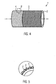
- Fig. 4 shows a charge air hose 1 according to the invention according to a second embodiment of the invention in a perspective view.
- the charge air hose 1 according to the invention of the second exemplary embodiment comprises a vulcanized elastomer hose 2 as the main body and a textile print carrier 3 arranged on or on the hose surface.
- the textile print carrier 3 is shown only symbolically and is preferably formed as a knit or braid of glass filaments.
- the textile printing substrate 3 is impregnated and / or coated with a coating material 4.
- the coating material 4 may be applied as desired in sections or completely over the hose length and the circumference of the tube.
- Fig. 5 shows a cross-sectional detail of the charge air hose 1 according to the invention of the second embodiment Fig. 4 ,
- Fig. 6 shows the charge air hose 1 according to the invention according to a third embodiment of the invention.
- the charge air hose 1 of the third exemplary embodiment according to the invention comprises a vulcanized elastomer hose 2 designed as a corrugated hose as the main body and a textile pressure carrier 3 arranged on the hose surface.
- the textile print carrier 3 is shown only symbolically and is preferably formed as a knit or braid of glass filaments. As in Fig. 6 can be seen, the textile print carrier 3 follows the contour of the molding tube or corrugated hose 2. In some wave troughs - each between two adjacent wave crests - a pressure ring 5 above the textile support 3 is arranged.
- Each pressure ring 5 is pushed onto the charge air hose 1 and brought by Caribbeannautschen the elastomeric hose 2 in its intended position in a trough between two wave crests of the corrugated hose 2.
- Each pressure ring 5 has the function of keeping the textile printing substrate 3 as close as possible to the contour of the corrugated hose 2 and to prevent tensioning of the textile pressure carrier 3 for bridging the corrugation valley when the charge air hose 1 is subjected to dynamic loading. As a result, the friction of the textile print carrier 3 is reduced to the hose surface 2.
- the textile print carrier 3 is embedded at the hose ends in a material connected materially to the base body 2, wherein this material is preferably a molded around the hose ends, elastomeric material.
- Fig. 7 shows the charge air hose 1 according to the invention according to a fourth embodiment of the invention.
- the charge air hose 1 according to the invention of the fourth embodiment comprises a formed as a corrugated hose vulcanized elastomeric hose 2 as a base body and arranged on or on the hose surface textile print carrier 3.
- the textile print carrier 3 is shown only symbolically and is preferably formed as a knitted or braided glass filaments.
- the charge air hose 1 according to the invention of the fourth embodiment substantially corresponds in construction to the charge air hose 1 according to the invention of the third embodiment, wherein additionally the flexible print carrier 3 is impregnated with the coating material 4 and / or coated.
- protective caps are arranged at the hose ends in order to enable a detachment of the textile print carrier 3 from the main body 2 and a coupling of the charge air hose 1.
- the yarn of the textile printing substrate 3 itself is equipped with an impregnation. As a result, the yarn / yarn friction is reduced at the cross points of the textile print carrier 3.
- the method according to the invention for producing the charge air hose 1 for motor vehicles comprises the steps of providing an elastomer-containing hose 2 as a tubular base body, vulcanizing the elastomer-containing hose 2 and applying the textile print carrier 3 to the surface of the vulcanized elastomer-containing hose 2.
- the textile print carrier 3 can be impregnated and / or coated with the coating material 4 before or after the application of the textile print carrier 3 to the surface of the vulcanized elastomer-containing tube 2.
- the yarn of the textile printing substrate 3 can be equipped with an impregnation 4 before the textile printing substrate 3 is produced.
- the textile print carrier 3 prior to application to the surface of the vulcanized, elastomer-containing tube 2, can be prefabricated or, for example, produced in a running process on the surface of the vulcanized elastomer-containing tube 2. This is for example the common braiding technology.
Landscapes
- Engineering & Computer Science (AREA)
- General Engineering & Computer Science (AREA)
- Mechanical Engineering (AREA)
- Chemical & Material Sciences (AREA)
- Combustion & Propulsion (AREA)
- Ceramic Engineering (AREA)
- Rigid Pipes And Flexible Pipes (AREA)
Abstract
Description
Die Erfindung betrifft einen Ladeluftschlauch für Kraftfahrzeuge, umfassend: einen schlauchförmigen Grundkörper und einen textilen Druckträger.The invention relates to a charge air hose for motor vehicles, comprising: a tubular body and a textile print carrier.
Aus dem Stand der Technik sind Ladeluftschläuche mit textilen Druckträgern bekannt, wobei der textile Druckträger in eine Elastomermatrix bzw. zwischen zwei Elastomerschichten eingebettet ist.The prior art discloses charge air hoses with textile print carriers, the textile print carrier being embedded in an elastomer matrix or between two elastomer layers.
Unter dynamischer Beanspruchung unterliegen die herkömmlichen, textilverstärkten Ladeluftschläuche einer hohen mechanischen Arbeit. Beide Komponenten, der Druckträger und die den Druckträger einbettende Matrix, weisen unterschiedliche Kraft-Dehnungsverhalten auf. Ist der Druckträger zwischen zwei Schichten positioniert, entstehen unter Belastung des Schlauchs Scherkräfte an den Verbindungsstellen Matrix/Druckträger, die zur Delamination des Verbundes und somit zu seinem Ausfall führen. Zusätzlich kommt es bei dynamischmechanischer Beanspruchung (durch die Expansion des Schlauches verursachte Dehnungen und überlagerte mechanische Zwangsbewegungen) aufgrund der Kerbwirkung des Druckträgers (hoher E-Modul im Vergleich zum Elastomer) zu Mikrorissen in der angrenzenden Elastomermatrix, die weiterhin als Ausgangspunkt eines Risswachstums anzusehen sind.Under dynamic stress, the conventional, textile-reinforced charge air hoses are subject to a high mechanical work. Both components, the print carrier and the matrix embedding the print carrier, have different force-elongation behavior. If the print carrier is positioned between two layers, shear forces at the connection points matrix / print carrier, which lead to the delamination of the composite and thus to its failure, arise under load of the hose. In addition, due to the notch effect of the print carrier (high modulus of elasticity compared to the elastomer), dynamic stress (expansions and superimposed mechanical constraints due to the expansion of the tube) leads to microcracks in the adjacent elastomer matrix, which continue to be considered the origin of crack growth.
Der Erfindung liegt die Aufgabe zugrunde, die aus dem Stand der Technik bekannten Probleme zu lösen, und insbesondere einen Ladeluftschlauch bereitzustellen, der unter dynamischer Beanspruchung eine gegenüber dem herkömmlichen Schlauch erheblich verlängerte Lebensdauer aufweist.The invention has for its object to solve the problems known from the prior art, and in particular to provide a charge air hose, which has a significantly extended compared to the conventional hose life under dynamic stress.
Um diese der Erfindung zugrunde liegende Aufgabe zu lösen, stellt die Erfindung den Ladeluftschlauch für Kraftfahrzeuge nach Anspruch 1 bereit, umfassend: einen schlauchförmigen Grundkörper, einen textilen Druckträger, der an der Oberfläche des Grundkörpers angeordnet ist, wobei der schlauchartige Grundkörper ein vulkanisierter, elastomerhaltiger Schlauch ist. Da der Druckträger an der Schlauchoberfläche angeordnet ist, weist der erfindungsgemäße Ladeluftschlauch nur noch eine einzige Verbindungsstelle zwischen dem Grundkörper und dem Druckträger auf. In einem herkömmlichen Herstellungsprozess wird der Druckträger auf einen Elastomer in unvulkanisiertem Zustand aufgebracht und mit mindestens einer Elastomerschicht bedeckt. Das Elastomer ist aufgrund des unvulkanisierten Zustands weich. Bedingt durch den weichen Zustand des Elastomers und durch die Garnspannung bei der Herstellung des textilen Druckträgers sowie anderen Prozessumständen dringt der Druckträger in die elastomere Oberfläche ein. Die Kontaktfläche zwischen dem Elastomer und dem Druckträger ist somit dreidimensional. Das Elastomer ummantelt die Garne des Druckträgers. Bei einer solchen Kontaktfläche und bei dynamischer Belastung des Schlauchs ist die Kraftübertragung zwischen dem Elastomer und dem textilen Druckträger sowohl kraftschlüssig (axial zum Garn) als auch formschlüssig (radial zum Garn). Die Formschlussverbindung weist eine sehr niedrige Tragfähigkeit auf und stellt somit schon bei niedriger Belastung des Schlauchs eine Schwachstelle dar, bei der sich der Druckträger vom Elastomer löst. Die so genannte Delamination ist umso mehr ausgeprägt, als die Garne in das Elastomer nicht vollständig eingebettet sind sondern nur ummantelt sind. Beim erfindungsgemäßen Ladeluftschlauch ist der textile Druckträger auf einen schon vulkanisierten, elastomerhaltigen Schlauch aufgebracht. Vorzugsweise ist der elastomerhaltige Schlauch vor dem Aufbringen des textilen Druckträgers vulkanisiert worden. Dies verringert die Reibung des textilen Druckträgers gegenüber dem elastomerhaltigen Schlauch bei dynamischer Beanspruchung. Der elastomerhaltige Schlauch ist im vulkanisierten Zustand hart und der Druckträger kann somit nicht in das elastomerhaltige Material eindringen. Die Kontaktfläche zwischen dem Druckträger und dem elastomerhaltigen Material ist die zweidimensionale Oberfläche des elastomerhaltigen Schlauchs. Die Kraftübertragung von der Schlauchoberfläche auf den Druckträger ist überwiegend formschlüssig (rechtwinklig zur Schlauchoberfläche) und somit im Idealfall ohne Reibung. Der erfindungsgemäße Ladeluftschlauch ist im Vergleich zu dem herkömmlichen Ladeluftschlauch sehr geeignet gegen dynamische Ermüdung.To solve this problem underlying the invention, the invention provides the charge air hose for motor vehicles according to
In einer weiteren bevorzugten Ausführung der Erfindung ist über dem textilen Druckträger zumindest ein Druckring angeordnet. Dies hat den Vorteil, dass der Druckring den textilen Druckträger eng an der Kontur des Grundkörpers hält.In a further preferred embodiment of the invention, at least one pressure ring is arranged above the textile pressure carrier. This has the advantage that the pressure ring holds the textile print carrier closely to the contour of the base body.
In einer weiteren bevorzugten Ausführung der Erfindung ist der schlauchförmige Grundkörper als Elastomerschlauch ausgebildet.In a further preferred embodiment of the invention, the tubular base body is formed as an elastomer hose.
In einer weiteren bevorzugten Ausführung der Erfindung weist der elastomerhaltige Schlauch eine im Wesentlichen glatte Oberfläche auf. Diese Maßnahme verringert die Reibung zwischen dem Druckträger und dem Grundkörper, was die Lebensdauer des erfindungsgemäßen Ladelufischlauchs bei dynamischer Beanspruchung erhöht.In a further preferred embodiment of the invention, the elastomer-containing tube has a substantially smooth surface. This measure reduces the friction between the print carrier and the main body, which increases the life of the charge air hose according to the invention under dynamic load.
In einer weiteren bevorzugten Ausführung der Erfindung ist der elastomerhaltige Schlauch im Extrusionsverfahren oder Spritzgussverfahren hergestellt. Diese Fertigungstechniken erweisen sich im Zusammenhang mit elastomerhaltigen Schläuchen als besonders wirtschaftlich.In a further preferred embodiment of the invention, the elastomer-containing tube is produced by extrusion or injection molding. These production techniques prove to be particularly economical in connection with elastomer-containing hoses.
In einer weiteren bevorzugten Ausführung der Erfindung weist der elastomerhaltige Schlauch einen thermoplastischen Elastomer auf. Durch Beigabe eines thermoplastischen Elastomers lassen sich die dynamischen und mechanischen Eigenschaften des Schlauchs gezielt einstellen.In a further preferred embodiment of the invention, the elastomer-containing tube to a thermoplastic elastomer. By adding a thermoplastic elastomer, the dynamic and mechanical properties of the hose can be adjusted specifically.
In einer weiteren bevorzugten Ausführung der Erfindung ist der textile Druckträger als Gestrick oder Geflecht ausgebildet. Dabei kann der Druckträger so ausgelegt werden, dass er formgerecht auf dem elastomerhaltigen Schlauch sitzt und dass seine Verformung den Bereich seiner Strukturdehnung nicht überschreitet. Der Druckträger befindet sich somit in einem niedrigeren Spannungszustand als bei dem herkömmlichen Ladeluftschlauch der Fall ist, der zudem über die gesamte Schlauchoberfläche gleichmäßig ist. Struktur- und Materialdehnung sind die zwei klassischen elastischen Dehnungszustände einer Textilstruktur. Im Bereich der Strukturdehnung wird eine Textilstruktur mit sehr niedrigen Kräften verformt. Der Grund liegt darin, dass die Garne in bestimmter, von der Textilstruktur (Gestrick, Geflecht) bedingter Weise aneinander gleiten können und die Textilstruktur somit andere Formen annehmen kann, ohne dass die Garne mechanisch belastet werden. Wird die Struktur weiter gedehnt, fängt der Bereich der Materialdehnung an. In dem letztgenannten Dehnungszustand wird die Garnstruktur belastet. Kleine Verformungen des Bauteils sind mit hohen Kräften verbunden. Diese Ausführung, bei der das Aufbringen des textilen Druckträgers auf den vulkanisierten, geformten, elastomerhaltigen Schlauch in der Form eines Gestricks oder Geflechts erfolgt, bringt die größte Freiheit bei der Konstruktion eines textilverstärkten, elastomerhaltigen Schlauchs mit sich. Jegliche existierende bzw. denkbare Textilstruktur kann eingesetzt werden, oder ebenfalls in einem definierten Spannungszustand aufgebracht werden. Dies eröffnet nicht nur den Einsatz von Ladeluftschläuchen für deutlich höhere Druckbereiche als die bisherigen im PKW-Bereich üblichen, sondern ermöglicht auch eine kontrollierte Volumenzunahme des Schlauchs im Betrieb, was zuletzt aufgrund des stets enger werdenden Bauraums im Motorraum einen bedeutenden Fortschritt darstellt. Eine solche Ausführung, bei welcher der textile Druckträger auf dem schon vulkanisierten, elastomerhaltigen Schlauch freischwimmend aufgebracht wird und auf dem er einen gleichmäßigen Spannungszustand aufweist, bringt ebenfalls einen bedeutenden Fortschritt mit sich. Die Textilstruktur ist enorm flexibel. Dies gilt insbesondere für die geflochtene Ausführung, da dort das dynamische bzw. mechanische Leistungsverhalten bei vorgegebener Kontur über den Geflechtswinkel bzw. Auszug definiert einstellbar ist. Die Feinheit bzw. Stärke des Garns ist gemäß dem jeweiligen Anforderungsprofil frei wählbar, da im Gegensatz zu einem innen liegenden Druckträger wie beim herkömmlichen Ladeluftschlauch keine Wechselwirkung (Kerbwirkung) zwischen dem Druckträger und der Matrix entsteht. Zusätzlich spielt auch bei herkömmlichen Ladeluftschläuchen die Haftung zwischen den Lagen eine wesentliche Rolle, insofern ist die Stärke des Garns limitiert. Je stärker das Garn, desto schlechter ist bereits die Lagenbindung im Originalzustand. Der Druckträger kann durch konturnahes Umflechten aufgebracht werden, was sich insbesondere bei Glattschläuchen eignet. Auch das Aufbringen eines vorgefertigten Geflechts oder Gestricks (z. B. vorgefertigter Geflechtschlauch) erweist sich als möglich, und eignet sich insbesondere bei Wellschläuchen.In a further preferred embodiment of the invention, the textile print carrier is formed as a knit or braid. In this case, the print carrier can be designed so that it sits properly on the elastomer-containing tube and that its deformation does not exceed the range of its structural extension. The print carrier is thus in a lower state of tension than in the conventional charge air hose is the case, which is also uniform over the entire hose surface. Structural and material elongation are the two classical elastic strain states of a textile structure. In the area of structural elongation, a textile structure is deformed with very low forces. The reason is that the yarns in certain, by the textile structure (knit fabric) conditional manner can slide together and the textile structure can thus take other forms without the yarns are mechanically stressed. If the structure is stretched further, the area of material expansion begins. In the latter elongated state, the yarn structure is loaded. Small deformations of the component are associated with high forces. This embodiment, in which the application of the textile printing substrate to the vulcanized molded elastomer-containing tube is in the form of a knit or braid, entails the greatest freedom in the construction of a textile-reinforced elastomer-containing tube. Any existing or conceivable textile structure can be used, or can also be applied in a defined state of tension. This not only opens up the use of charge air hoses for significantly higher pressure ranges than the previous usual in the passenger car sector, but also allows a controlled increase in volume of the hose during operation, which represents a significant progress recently due to the ever-narrowing space in the engine compartment. Such an embodiment, in which the textile print carrier is applied in a floating manner on the already vulcanized, elastomer-containing tube and on which it has a uniform state of stress, also brings a significant Progress with yourself. The textile structure is enormously flexible. This applies in particular to the braided design, since there the dynamic or mechanical performance behavior can be set in a defined manner via the braid angle or extension. The fineness or strength of the yarn is freely selectable according to the respective requirement profile, since, in contrast to an internal print carrier as in the conventional charge air hose no interaction (notch effect) between the print carrier and the matrix is formed. In addition, the adhesion between the layers also plays a significant role in conventional charge air hoses, insofar the strength of the yarn is limited. The stronger the yarn, the worse the ply binding is in the original condition. The print carrier can be applied by conformal braiding, which is particularly suitable for straight tubes. The application of a prefabricated braiding or knitted fabric (eg prefabricated braided sleeving) also proves to be possible, and is particularly suitable for corrugated tubes.
In einer weiteren bevorzugten Ausführung der Erfindung ist der textile Druckträger aus Glasfilament hergestellt. Glasfilamente gehören zu den hochfesten Garnmaterialien, sind preiswert und zeichnen sich durch hohe thermische und gute chemische Beständigkeit sowie sehr niedrige Dehnbarkeit aus.In a further preferred embodiment of the invention, the textile print carrier is made of glass filament. Glass filaments are among the high-strength yarn materials, are inexpensive and are characterized by high thermal and good chemical resistance and very low ductility.
In einer weiteren bevorzugten Ausführung der Erfindung ist der textile Druckträger als 3D-Geflecht ausgebildet. Diese Fertigungstechnik des textilen Druckträgers ermöglicht eine besonders hohe Anpassung an die Form des Grundkörpers und damit eine besonders geringe Relativbewegung des textilen Druckträgers zum Grundkörper bei dynamischer Beanspruchung des erfindungsgemäßen Ladeluftschlauchs.In a further preferred embodiment of the invention, the textile print carrier is designed as a 3D braid. This production technology of the textile printing substrate allows a particularly high adaptation to the shape of the base body and thus a particularly small relative movement of the textile printing substrate to the body under dynamic stress of the charge air hose according to the invention.
In einer weiteren bevorzugten Ausführung der Erfindung umgibt der textile Druckträger den Formschlauch formgerecht. Dadurch findet bei dynamischer Beanspruchung des erfindungsgemäßen Ladeluftschlauchs eine geringe Relativbewegung zwischen Grundkörper und Druckträger statt.In a further preferred embodiment of the invention, the textile printing substrate surrounds the molding tube in a form-fitting manner. As a result, under dynamic loading of the charge air hose according to the invention, a slight relative movement takes place between the base body and the pressure carrier.
In einer besonders bevorzugten Ausführung der Erfindung ist der textile Druckträger mit einem Beschichtungsmaterial imprägniert und/oder beschichtet. Dies schützt den Druckträger vor Verschleiß, z. B. durch Reibung. Weiterhin werden das Garn bzw. der textile Druckträger schnittfest ausgerüstet und somit vor Ausfransen der einzelnen Filamente geschützt. Im Übrigen dient die Imprägnierung oder Beschichtung des Druckträgers der Fixierung auf der Schlauchoberfläche bzw. der Montagehaftung. Zudem werden die Garnfilamente im Hinblick auf die Anbindung (z. B. an ein Ladeluftrohr mittels Schlauchschelle, Kupplungen, etc.) besser geschützt. Bei dieser Ausführung ist die nachträgliche Imprägnierung bei konturnahen Oberflächen möglich, ebenso wie die direkte Beschichtung des textilen Druckträgers nach dem Flechtprozess bei vorgefertigten Geflechtschläuchen.In a particularly preferred embodiment of the invention, the textile printing substrate is impregnated and / or coated with a coating material. This protects the print carrier from wear, eg. B. by friction. Furthermore, the yarn or the textile print carrier are cut-resistant and thus protected against fraying of the individual filaments. In addition, the impregnation or coating of the print carrier serves to fix the tube surface or the mounting adhesion. In addition, the yarn filaments in the With regard to the connection (eg to a charge air pipe by means of a hose clamp, couplings, etc.) better protected. In this embodiment, the subsequent impregnation is possible with conformal surfaces, as well as the direct coating of the textile print carrier after the braiding process in prefabricated braided sleeving.
In einer weiteren bevorzugten Ausführung der Erfindung ist das Garn des textilen Druckträgers mit einer Imprägnierung versehen. Die Imprägnierung erfolgt vorzugsweise vor der Fertigung des textilen Druckträgers, d.h. vor dem Flechten oder Stricken. Auch diese Maßnahme dient dem Schutz des Garns und des textilen Druckträgers vor Verschleiß. Dieser Schutz ist besonders an den Garnkreuzungspunkten des textilen Druckträgers wichtig, die eine Schwachstelle hinsichtlich Garn/Garn-Reibung darstellen..In a further preferred embodiment of the invention, the yarn of the textile printing substrate is provided with an impregnation. The impregnation preferably takes place before the production of the textile printing substrate, i. before braiding or knitting. This measure also serves to protect the yarn and the textile print carrier from wear. This protection is particularly important at the yarn crossing points of the textile print carrier, which are a weak point in yarn / yarn friction.
In einer weiteren bevorzugten Ausführung der Erfindung ist das Beschichtungsmaterial ein Harz oder ein Elastomer, vorzugsweise ein Silikonelastomer. Als Werkstoff eignet sich die flexible Harz- oder Elastomerbeschichtung z. B in Form von Lösungen oder Latizes. Bei Verwendung eines textilen Druckträgers aus Glasfilamenten wird als Beschichtungsmaterial vorzugsweise ein haftmodifizierter Silikonelastomer verwendet, wodurch eine universelle Temperaturbeständigkeit, hohe Flexibilität und gute Haftung zu den Glasfaserfilamenten erzielbar ist.In a further preferred embodiment of the invention, the coating material is a resin or an elastomer, preferably a silicone elastomer. As a material, the flexible resin or elastomer coating z. B in the form of solutions or latexes. When using a textile print carrier made of glass filaments is preferably used as a coating material, an adhesion-modified silicone elastomer, whereby a universal temperature resistance, high flexibility and good adhesion to the glass fiber filaments can be achieved.
In einer bevorzugten Ausführung der Erfindung wird das Beschichtungsmaterial durch Tauchen, Lackieren oder Umspritzen des Ladeluftschlauchs, oder durch Extrusion bei Geflechtsschläuchen mit nachträglicher Vernetzung aufgetragen, da das elastomere Beschichtungsmaterial grundsätzlich nach dem Auftrag vulkanisiert werden muss, bevorzugt durch ein Online-Verfahren.In a preferred embodiment of the invention, the coating material is applied by dipping, painting or encapsulation of the charge air hose, or by extrusion in braided sleeving with subsequent crosslinking, since the elastomeric coating material must always be vulcanized after application, preferably by an on-line process.
In einer weiteren bevorzugten Ausführung der Erfindung ist das Beschichtungsmaterial in einer gegenüber dem Grundkörper und/oder dem Druckträger unterschiedlichen Farbe eingefärbt. So ist eine Kennzeichnung des Ladeluftschlauchs durch die Beschichtung möglich.In a further preferred embodiment of the invention, the coating material is dyed in a different color from the main body and / or the print carrier. Thus, a labeling of the charge air hose through the coating is possible.
In einer weiteren bevorzugten Ausführung der Erfindung ist der textile Druckträger an zumindest einem Schlauchende in ein mit dem Grundkörper stoffschlüssig verbundenes Material eingebettet. Vorzugsweise ist der Ladeluftschlauch dazu an dem Schlauchende umspritzt. Dies verhindert ein Ablösen oder Ausfransen des textilen Druckträgers und dient der Funktionalisierung der Schlauchenden im Hinblick auf die Anbindung und Integration von Funktionen, z. B. im Schellensitz, Schellenfixierung, Einbaumarkierungen, etc.In a further preferred embodiment of the invention, the textile print carrier is embedded on at least one end of the tube in a cohesively connected to the body material. Preferably, the charge air hose is encapsulated at the hose end. This prevents detachment or fraying of the textile print carrier and serves to functionalize the hose ends with regard to the connection and integration of functions, eg. B. in the clamp seat, clamp fixation, installation marks, etc.
In einer weiteren bevorzugten Ausführung der Erfindung ist an zumindest einem Schlauchende eine Kappe, vorzugsweise Elastomerkappe, aufgeklebt und/oder aufvulkanisiert. Dabei eignen sich funktionalisierte elastomere Schlauchabschnitte zum Aufkleben oder Aufvulkanisieren auf die Schlauchenden.In a further preferred embodiment of the invention, a cap, preferably an elastomer cap, is glued and / or vulcanized on at least one end of the hose. Functionalized elastomeric hose sections are suitable for gluing or vulcanising onto the hose ends.
Eine weitere bevorzugte Ausführungsform der Erfindung betrifft ein Verfahren zum Herstellen eines Ladeluftschlauches für Kraftfahrzeuge, umfassend die Schritte: Bereitstellen eines elastomerhaltigen Schlauchs als schlauchförmigen Grundkörper, Vulkanisieren des elastomerhaltigen Schlauchs und Aufbringen eines textilen Druckträgers auf die Oberfläche des vulkanisierten, elastomerhaltigen Schlauchs.A further preferred embodiment of the invention relates to a method for producing a charge air hose for motor vehicles, comprising the steps of providing an elastomer-containing hose as a tubular body, vulcanizing the elastomer-containing hose and applying a textile print carrier to the surface of the vulcanized elastomer-containing hose.
Eine weitere bevorzugte Ausführung des erfindungsgemäßen Verfahrens umfasst das Imprägnieren und/oder Beschichten des textilen Druckträgers mit einem Beschichtungsmaterial zur Verringerung des Verschleißes des textilen Druckträgers.A further preferred embodiment of the method according to the invention comprises impregnating and / or coating the textile printing substrate with a coating material for reducing the wear of the textile printing substrate.
Eine weitere bevorzugte Ausführung des erfindungsgemäßen Verfahrens umfasst das Imprägnieren des Garns des textilen Druckträgers mit dem Ziel der Verringerung des Verschleißes des textilen Druckträgers durch Verringerung der Garn/Garn-Reibung an den Kreuzungspunkten des textilen Druckträgers.A further preferred embodiment of the method according to the invention comprises impregnating the yarn of the textile printing substrate with the aim of reducing the wear of the textile printing substrate by reducing the yarn / yarn friction at the crossing points of the textile printing substrate.
Eine weitere bevorzugte Ausführung des erfindungsgemäßen Verfahrens umfasst das Umstricken, Umweben oder Umflechten des elastomerhaltigen Schlauchs zum Auftragen des textilen Druckträgers.A further preferred embodiment of the method according to the invention comprises the knitting, interweaving or braiding of the elastomer-containing tube for applying the textile print carrier.
Bevorzugte Ausführungsbeispiele und Merkmale der Erfindung werden nachstehend mit Bezug auf die beiliegenden Zeichnungen beschrieben.Preferred embodiments and features of the invention will be described below with reference to the accompanying drawings.
- Fig. 1Fig. 1
- zeigt eine perspektivische Ansicht des erfindungsgemäßen Ladeluftschlauchs gemäß einem ersten Ausführungsbeispiel, mit einem elastomerhaltigen Schlauch als Grundkörper und einem textilen Druckträger an der Schlauchoberfläche.shows a perspective view of the charge air hose according to the invention according to a first embodiment, with an elastomeric hose as the base body and a textile print carrier on the hose surface.
- Fig. 2Fig. 2
-
zeigt einen Querschnittsausschnitt des erfindungsgemäßen Ladeluftschlauchs aus
Fig. 1 .shows a cross-sectional detail of the charge air hose according to the inventionFig. 1 , - Fig. 3Fig. 3
-
zeigt einen Querschnittsausschnitt des erfindungsgemäßen Ladeluftschlauchs aus
Fig. 1 , wobei der Garn des textilen Druckträgers imprägniert bzw. beschichtet ist.shows a cross-sectional detail of the charge air hose according to the inventionFig. 1 , wherein the yarn of the textile printing substrate is impregnated or coated. - Fig. 4Fig. 4
- zeigt eine perspektivische Ansicht des erfindungsgemäßen Ladeluftschlauchs gemäß einem zweiten Ausführungsbeispiel, mit einem elastomerhaltigen Schlauch als Grundkörper, einem textilen Druckträger an der Schlauchoberfläche und einer auf den textilen Druckträger aufgebrachten Imprägnierung bzw. Beschichtung.shows a perspective view of the charge air hose according to the invention according to a second embodiment, with an elastomer-containing hose as the base body, a textile print carrier on the hose surface and an applied to the textile print carrier impregnation or coating.
- Fig. 5Fig. 5
-
zeigt einen Querschnittsausschnitt des erfindungsgemäßen Ladeluftschlauchs des zweiten Ausführungsbeispiels aus
Fig. 4 .shows a cross-sectional detail of the charge air hose according to the invention of the second embodimentFig. 4 , - Fig. 6Fig. 6
- zeigt eine perspektivische Ansicht des erfindungsgemäßen Ladeluftschlauchs gemäß einem dritten Ausführungsbeispiel, mit einem elastomerhaltigen Schlauch als Grundkörper, einem textilen Druckträger an der Schlauchoberfläche, wobei der elastomerhaltige Schlauch als Wellschlauch ausgebildet ist, und wobei von mehreren Druckringen jeweils ein Druckring in einem Wellental zwischen zwei benachbarten Wellenbergen des Wellschlauchs über dem textilen Druckträger angeordnet ist.shows a perspective view of the charge air hose according to the invention according to a third embodiment, comprising an elastomeric hose as a base body, a textile print carrier on the hose surface, wherein the elastomeric hose is formed as a corrugated tube, and wherein a plurality of pressure rings each a pressure ring in a trough between two adjacent wave crests of the corrugated hose is arranged above the textile print carrier.
- Fig. 7Fig. 7
- zeigt eine perspektivische Ansicht des erfindungsgemäßen Ladeluftschlauchs gemäß einem vierten Ausführungsbeispiel, mit einem elastomerhaltigen Schlauch als Grundkörper, einem textilen Druckträger an der Schlauchoberfläche, wobei der elastomerhaltige Schlauch als Wellschlauch, ausgebildet ist, und wobei von mehreren Druckringen jeweils ein Druckring in einem Wellental zwischen zwei benachbarten Wellenbergen des Wellschlauchs über dem textilen Druckträger angeordnet ist, wobei auf dem textilen Druckträger abschnittsweise eine Imprägnierung bzw. Beschichtung aufgetragen ist.shows a perspective view of the charge air hose according to the invention according to a fourth embodiment, with an elastomeric hose as the base body, a textile pressure carrier on the hose surface, wherein the elastomeric hose is formed as a corrugated hose, and wherein a plurality of pressure rings each have a pressure ring in a trough between two adjacent Wave crests of the corrugated hose is arranged above the textile printing substrate, wherein on the textile printing substrate sections impregnation or coating is applied.
Die Erfindung betrifft einen Ladeluftschlauch 1 für Kraftfahrzeuge, umfassend: einen schlauchförmigen Grundkörper 2, einen textilen Druckkörper 3, der auf der Oberfläche des Grundkörpers 2 angeordnet ist, wobei der schlauchförmige Grundkörper 2 ein vulkanisierter, elastomerhaltiger Schlauch ist. Der elastomerhaltige Schlauch 2 des erfindungsgemäßen Ladeluftschlauchs 1 ist als Elastomerschlauch ausgebildet und ist bereits vor dem Aufbringen des Textildruckträgers 3 vulkanisiert worden. Der elastomerhaltige Schlauch 2 weist zudem eine im Wesentlichen glatte Oberfläche auf. Je nach Ausführungsform wird der elastomerhaltige Schlauch 2 im Extrusionsverfahren oder Spritzgussverfahren hergestellt. In einer bevorzugten Ausführung der Erfindung ist der elastomerhaltige Schlauch 2 als Formschlauch, vorzugsweise als Wellschlauch, ausgebildet. Zur Herstellung des elastomerhaltigen Schlauchs 2 können alle elastomeren Werkstoffe, insbesondere auch thermoplastische Elastomere verwendet werden.The invention relates to a
Als textiler Druckträger 3 wird ein Gestrick oder Geflecht bezeichnet, das erfindungsgemäß an bzw. auf der Oberfläche des schlauchförmigen Grundkörpers 2 angeordnet ist, um eine Volumenzunahme des Schlauchs 2 zu begrenzen. Vorzugsweise ist der textile Druckträger 2 aus Glasfilamenten hergestellt. Auch in den bevorzugten Ausführungsbeispielen der Erfindung, in welchen der elastomerhaltige Schlauch als Formschlauch bzw. Wellschlauch ausgebildet ist, umgibt der textile Druckträger 3 den Formschlauch 2 formgerecht. Dabei wird der textile Druckträger 3 als Geflecht ausgebildet, das z.B. nach dem Rundflechten, nach dem 3D-Flechten und/oder nach dem Umflechten eines endkonturnahen Kerns hergestellt ist. Vorzugsweise sind Druckringe 5, bevorzugt aus Kunststoff oder Metall, in den Wellentälern des Wellschlauchs 2 angeordnet, um den textilen Druckträger 3 in den Wellentälern möglichst eng an der Schlauchoberfläche zu halten.As a
Vorzugsweise ist der textile Druckträger 3 mit einem Beschichtungsmaterial 4 imprägniert und/oder beschichtet. Das Beschichtungsmaterial 4 ist vorzugsweise ein Harz oder ein Elastomer, bevorzugt ein Silikonelastomer. Alternativ oder zusätzlich kann das Garn des textilen Druckträgers 3 mit dem Beschichtungsmaterial 4 imprägniert sein. Das Beschichtungsmaterial 4 wird vorzugsweise durch Tauchen, Lackieren oder Umspritzen des Ladeluftschlauchs 1 oder des vorgefertigten textilen Druckträgers selbst, d.h. vor dem Aufbringen auf die Oberfläche des vulkanisierten, elastomerhaltigen Schlauchs 2, aufgetragen. Die Garnimprägnierung erfolgt vor der Fertigung des textilen Druckträgers 3. Nach Belieben ist das Beschichtungsmaterial 4 in der Farbe des Grundkörpers 2 und/oder Druckträgers 3 oder in einer gegenüber dem Grundkörper 2 und/oder Druckträger 3 unterschiedlichen Farbe eingefärbt, um den Ladeluftschlauch 1 über das Beschichtungsmaterial 4 einzufärben und/oder zu kennzeichnen.Preferably, the
Um die Schlauchenden im Hinblick an die Anbindung und Integration von Funktionen, z. B. Schellensitz, Schellenfixierung, Einbaumarkierungen, zu funktionalisieren, können die Schlauchenden umspritzt sein oder es können vorgefertigte Kappen; vorzugsweise Elastomerkappen, oder funktionalisierte, elastomere Schlauchabschnitte aufgeklebt und/oder aufvulkanisiert werden.To the hose ends with regard to the connection and integration of functions, eg. B. Schellensitz, clamp fixation, built-in markers to functionalize, the hose ends can be encapsulated or there may be prefabricated caps; preferably elastomeric caps, or functionalized, elastomeric tube sections are glued and / or vulcanized.
Die vorangehend genannten Merkmale der Erfindung können in beliebiger Weise kombiniert werden.The aforementioned features of the invention can be combined in any manner.
Ein erstes Ausführungsbeispiel der Erfindung wird nachstehend mit Bezug auf die
Der textile Druckträger 3 ist lediglich symbolisch dargestellt und ist vorzugsweise als Gestrick oder Geflecht aus Glasfilamenten ausgebildet. Wie in
The
Die Merkmale der genannten und beschriebenen Ausführungsbeispiele können in beliebiger Weise kombiniert werden.The features of the aforementioned and described embodiments can be combined in any way.
Das erfindungsgemäße Verfahren zum Herstellen des Ladeluftschlauchs 1 für Kraftfahrzeuge umfasst die Schritte: Bereitstellen eines elastomerhaltigen Schlauchs 2 als schlauchförmigen Grundkörper, Vulkanisieren des elastomerhaltigen Schlauchs 2 und Aufbringen des textilen Druckträgers 3 auf die Oberfläche des vulkanisierten, elastomerhaltigen Schlauchs 2.The method according to the invention for producing the
Um den erfindungsgemäßen Ladeluftschlauch 1 mit zusätzlichen vorteilhaften Eigenschaften zu versehen, kann der textile Druckträger 3 vor oder nach dem Aufbringen des textilen Druckträgers 3 auf die Oberfläche des vulkanisierten, elastomerhaltigen Schlauchs 2 mit dem Beschichtungsmaterial 4 imprägniert und/oder beschichtet werden. Alternativ oder zusätzlich kann das Garn des textilen Druckträgers 3 vor der Fertigung des textilen Druckträgers 3 mit einer Imprägnierung 4 ausgerüstet werden. Überdies kann der textile Druckträger 3 vor dem Aufbringen auf die Oberfläche des vulkanisierten, elastomerhaltigen Schlauchs 2 vorgefertigt oder beispielsweise in einem laufenden Verfahren auf der Oberfläche des vulkanisierten, elastomerhaltigen Schlauchs 2 erzeugt werden. Dazu eignet sich beispielsweise die gängige Umflechttechnologie.In order to provide the
Claims (23)
Applications Claiming Priority (1)
| Application Number | Priority Date | Filing Date | Title |
|---|---|---|---|
| DE102007009906A DE102007009906A1 (en) | 2007-02-28 | 2007-02-28 | Charge air hose |
Publications (1)
| Publication Number | Publication Date |
|---|---|
| EP1964706A1 true EP1964706A1 (en) | 2008-09-03 |
Family
ID=39433269
Family Applications (1)
| Application Number | Title | Priority Date | Filing Date |
|---|---|---|---|
| EP07024832A Withdrawn EP1964706A1 (en) | 2007-02-28 | 2007-12-20 | Charge air hose |
Country Status (3)
| Country | Link |
|---|---|
| US (1) | US8220498B2 (en) |
| EP (1) | EP1964706A1 (en) |
| DE (1) | DE102007009906A1 (en) |
Cited By (3)
| Publication number | Priority date | Publication date | Assignee | Title |
|---|---|---|---|---|
| EP2497987A1 (en) * | 2011-03-10 | 2012-09-12 | Siemens Aktiengesellschaft | Flexible steam conduit, particularly for solar thermal power plants |
| EP2562409A1 (en) * | 2011-08-24 | 2013-02-27 | MANN+HUMMEL GmbH | Duct for a fluid |
| EP3498449A1 (en) * | 2017-12-14 | 2019-06-19 | ContiTech Kühner GmbH & Cie. KG | Method for manufacturing an air conditioning hose and device for performing the method |
Families Citing this family (17)
| Publication number | Priority date | Publication date | Assignee | Title |
|---|---|---|---|---|
| WO2007109837A1 (en) | 2006-03-24 | 2007-10-04 | Resmed Ltd | Air delivery conduit |
| DE102008049497A1 (en) * | 2008-09-29 | 2010-04-01 | Witzenmann Gmbh | Flexible conducting element has metal bellow or metal corrugated hose, which is surrounded by network, where bend protection elements are arranged externally at conducting element |
| DE102008058741B4 (en) * | 2008-11-24 | 2010-12-16 | Veritas Ag | Method and device for producing a curved molding tube |
| DE102009015985A1 (en) * | 2009-04-02 | 2010-10-07 | Veritas Ag | Hose for conveying pressurized media |
| EP4039311B1 (en) * | 2011-03-15 | 2024-07-31 | ResMed Pty Ltd | Air delivery conduit |
| DE102012210045A1 (en) | 2012-06-14 | 2013-12-19 | Senior Flexonics Gmbh | Pipe component and method for producing a pipe component |
| US9279399B2 (en) * | 2013-02-21 | 2016-03-08 | Ford Global Technologies, Llc | Air trap variable manifold runners |
| SE542603C2 (en) * | 2013-10-07 | 2020-06-16 | Sten Corfitsen | Procedure and device for automatic refueling of vehicles |
| US20150167868A1 (en) * | 2013-12-17 | 2015-06-18 | Scott Boncha | Maple sap vacuum collection systems with chew proof tubing |
| FR3017179B1 (en) * | 2014-02-06 | 2016-02-26 | Dcns | MODULAR TRUNK FOR A WATER PIPE, WATER CONDUIT COMPRISING SUCH STRINGS AND THERMAL ENERGY SYSTEM OF THE SEAS COMPRISING SUCH A WATER CONDUIT |
| KR20170009919A (en) * | 2014-05-28 | 2017-01-25 | 트렐레보리 인더스트리 에스에이에스 | Cryogenic transfer hose |
| DE112015004987T5 (en) * | 2014-11-03 | 2017-07-27 | Cummins Inc. | METHOD FOR SUPPORTING LOAD AIR TUBES AND HANDLING OF HEAT EXTENSION BY MEANS OF A WEAR SLEEVE |
| US10323711B2 (en) * | 2017-05-23 | 2019-06-18 | Ford Global Technologies, Llc | Breakable duct for use with a motor vehicle air induction system |
| DE102018111191B4 (en) | 2018-05-09 | 2022-05-12 | Montaplast Gmbh | air duct for motor vehicles |
| US20200003355A1 (en) * | 2018-06-28 | 2020-01-02 | Contitech Techno-Chemie Gmbh | Abrasion resistant patch for elastomeric hoses |
| DE102019104509B4 (en) * | 2019-02-22 | 2021-05-27 | Dr. Ing. H.C. F. Porsche Aktiengesellschaft | Method for manufacturing a charge air hose |
| CN110608320A (en) * | 2019-09-17 | 2019-12-24 | 一汽解放汽车有限公司 | Thin-wall high-temperature-resistant high-pressure-resistant intercooler corrugated pipe |
Citations (13)
| Publication number | Priority date | Publication date | Assignee | Title |
|---|---|---|---|---|
| DE2325342A1 (en) * | 1972-05-19 | 1973-11-29 | Rhone Poulenc Sa | NON-FLAMMABLE FLEXIBLE TUBES WITH CONSTANT DIAMETER |
| DE7320996U (en) * | 1972-07-06 | 1976-10-14 | Imperial-Eastman Corp., Chicago, Ill. (V.St.A.) | TUBE |
| EP0380841A2 (en) * | 1989-02-02 | 1990-08-08 | Teleflex Incorporated | Coated braided hose method and assembly |
| DE4315175A1 (en) * | 1993-05-07 | 1994-11-10 | Rasmussen Gmbh | Flexible pipe |
| WO1995013495A1 (en) * | 1993-11-11 | 1995-05-18 | Bentley Harris Manufacturing Co. | Integrally flanged flexible sleeve |
| DE19524394C1 (en) * | 1995-07-04 | 1997-01-09 | Tecalemit Gmbh Deutsche | Expansion hose |
| DE19754448C2 (en) * | 1997-12-08 | 2000-11-23 | Milliken Europ Nv | Textile reinforcement layer for hoses, pipes and similar elongated bodies and products made with them |
| EP1114959A2 (en) * | 2000-01-04 | 2001-07-11 | Cesare Parigi | High-strength, durably-flexible hose for hydraulic coupling applications |
| DE202004014284U1 (en) * | 2004-03-05 | 2004-11-25 | Veritas Ag | Flexible hose, especially charge air hose |
| DE202004019440U1 (en) * | 2004-12-16 | 2006-05-24 | Veritas Ag | Connecting device for e.g. internal combustion engine has retainer ring, provided on corrugated hose and adjacent to end-sided corrugated crest, which presses the respective ends of plaited flexible hose against corrugated hose |
| DE102004053985A1 (en) * | 2004-11-09 | 2006-06-08 | Stabil Verbindungstechnik Gmbh | Support ring for a flexible piping for conveying a fluid under pressure is made from tensile plastic formed in the peripheral direction |
| DE102005016154A1 (en) * | 2004-11-12 | 2006-10-19 | Cohnen Beteiligungs-Gmbh & Co. Kg | Braided metal sleeve for fitting on rubber hoses has cylindrical bush fitted on one end, second bush of larger diameter then being fitted over sleeve, so that it is held between two bushes |
| EP1746325A2 (en) * | 2005-07-22 | 2007-01-24 | Veritas Ag | Stabilization mechanism for a corrugated tube and a method of application of the stabilization mechanism on a corrugated tube |
Family Cites Families (10)
| Publication number | Priority date | Publication date | Assignee | Title |
|---|---|---|---|---|
| US3626988A (en) * | 1969-11-12 | 1971-12-14 | Resistoflex Corp | Unbonded cloth reinforced bellows and method of manufacture |
| US3682202A (en) * | 1970-01-22 | 1972-08-08 | Goodyear Tire & Rubber | Reinforced hose |
| US3988189A (en) * | 1973-09-14 | 1976-10-26 | Parker-Hannifin Corporation | Method of constructing a hose |
| US3953270A (en) * | 1974-11-05 | 1976-04-27 | General Motors Corporation | Manufacture of reinforced elastomeric hose |
| US4238260A (en) * | 1978-11-13 | 1980-12-09 | Parker-Hannifin Corporation | Method of making an elastomeric hose |
| US20040040607A1 (en) * | 2002-08-28 | 2004-03-04 | Wilson Reji Paul | Refrigerant hose |
| DE3108795A1 (en) * | 1981-03-07 | 1982-09-16 | Hoechst Ag, 6000 Frankfurt | FOR FOODSTUFFS, ESPECIALLY SAUSAGE PRODUCTS, SUITABLE FIBER-REINFORCED HOSE COVER AND METHOD FOR THEIR PRODUCTION |
| EP0797039B1 (en) * | 1996-03-20 | 2002-10-16 | Witzenmann GmbH | Pipe member having a metal bellows |
| BRPI0402583A (en) * | 2003-07-11 | 2005-05-31 | Goodyear Tire & Rubber | Refrigerant hose |
| DE102004037088B3 (en) * | 2004-07-30 | 2006-04-13 | Veritas Ag | Flexible hose, preferably charge air hose for motor vehicles |
-
2007
- 2007-02-28 DE DE102007009906A patent/DE102007009906A1/en not_active Withdrawn
- 2007-12-20 EP EP07024832A patent/EP1964706A1/en not_active Withdrawn
-
2008
- 2008-02-27 US US12/071,906 patent/US8220498B2/en not_active Expired - Fee Related
Patent Citations (13)
| Publication number | Priority date | Publication date | Assignee | Title |
|---|---|---|---|---|
| DE2325342A1 (en) * | 1972-05-19 | 1973-11-29 | Rhone Poulenc Sa | NON-FLAMMABLE FLEXIBLE TUBES WITH CONSTANT DIAMETER |
| DE7320996U (en) * | 1972-07-06 | 1976-10-14 | Imperial-Eastman Corp., Chicago, Ill. (V.St.A.) | TUBE |
| EP0380841A2 (en) * | 1989-02-02 | 1990-08-08 | Teleflex Incorporated | Coated braided hose method and assembly |
| DE4315175A1 (en) * | 1993-05-07 | 1994-11-10 | Rasmussen Gmbh | Flexible pipe |
| WO1995013495A1 (en) * | 1993-11-11 | 1995-05-18 | Bentley Harris Manufacturing Co. | Integrally flanged flexible sleeve |
| DE19524394C1 (en) * | 1995-07-04 | 1997-01-09 | Tecalemit Gmbh Deutsche | Expansion hose |
| DE19754448C2 (en) * | 1997-12-08 | 2000-11-23 | Milliken Europ Nv | Textile reinforcement layer for hoses, pipes and similar elongated bodies and products made with them |
| EP1114959A2 (en) * | 2000-01-04 | 2001-07-11 | Cesare Parigi | High-strength, durably-flexible hose for hydraulic coupling applications |
| DE202004014284U1 (en) * | 2004-03-05 | 2004-11-25 | Veritas Ag | Flexible hose, especially charge air hose |
| DE102004053985A1 (en) * | 2004-11-09 | 2006-06-08 | Stabil Verbindungstechnik Gmbh | Support ring for a flexible piping for conveying a fluid under pressure is made from tensile plastic formed in the peripheral direction |
| DE102005016154A1 (en) * | 2004-11-12 | 2006-10-19 | Cohnen Beteiligungs-Gmbh & Co. Kg | Braided metal sleeve for fitting on rubber hoses has cylindrical bush fitted on one end, second bush of larger diameter then being fitted over sleeve, so that it is held between two bushes |
| DE202004019440U1 (en) * | 2004-12-16 | 2006-05-24 | Veritas Ag | Connecting device for e.g. internal combustion engine has retainer ring, provided on corrugated hose and adjacent to end-sided corrugated crest, which presses the respective ends of plaited flexible hose against corrugated hose |
| EP1746325A2 (en) * | 2005-07-22 | 2007-01-24 | Veritas Ag | Stabilization mechanism for a corrugated tube and a method of application of the stabilization mechanism on a corrugated tube |
Cited By (4)
| Publication number | Priority date | Publication date | Assignee | Title |
|---|---|---|---|---|
| EP2497987A1 (en) * | 2011-03-10 | 2012-09-12 | Siemens Aktiengesellschaft | Flexible steam conduit, particularly for solar thermal power plants |
| EP2562409A1 (en) * | 2011-08-24 | 2013-02-27 | MANN+HUMMEL GmbH | Duct for a fluid |
| CN102953876A (en) * | 2011-08-24 | 2013-03-06 | 曼·胡默尔有限公司 | Duct for fluid |
| EP3498449A1 (en) * | 2017-12-14 | 2019-06-19 | ContiTech Kühner GmbH & Cie. KG | Method for manufacturing an air conditioning hose and device for performing the method |
Also Published As
| Publication number | Publication date |
|---|---|
| US20080202620A1 (en) | 2008-08-28 |
| US8220498B2 (en) | 2012-07-17 |
| DE102007009906A1 (en) | 2008-09-04 |
Similar Documents
| Publication | Publication Date | Title |
|---|---|---|
| EP1964706A1 (en) | Charge air hose | |
| DE60203782T2 (en) | THERMOPLASTIC, REINFORCED HOSE CONSTRUCTION | |
| EP2422966B1 (en) | Method for manufacturing charge air hoses | |
| EP3071423B1 (en) | Hybridyarn | |
| EP2710279B1 (en) | Drive belt having a reinforcement band or a braided reinforcement section or having reinforcement elements arranged in some zones within the carcass | |
| EP2252821B1 (en) | Flexible hose for high pressures and temperatures, in particular charge air or cooling water hose | |
| EP3441237A1 (en) | Hybrid cord for use as a support in a belt of a pneumatic vehicle tyre | |
| EP2234801B1 (en) | Reinforced hose | |
| EP3073002B1 (en) | Reinforcing substrate for elastomer products, in particular for the belt cover layer of vehicle pneumatic tyres | |
| EP2764992B1 (en) | Flexible hose | |
| EP2977191B1 (en) | Method for the fabrication of hose blanks | |
| EP1482079B1 (en) | Textile yarn, fabric and component made therefrom | |
| US6413637B2 (en) | Shape memory cords for reinforcing articles made from elastomeric material | |
| EP2865541B1 (en) | Hybrid reinforcing substrate for elastomer products, in particular for the carcass of vehicle pneumatic tyres | |
| EP1773606A1 (en) | Reinforcing cord for elastomeric products | |
| DE102009051503A1 (en) | Molded hose useful for fuel applications, comprises a barrier layer, and an elastomeric layer, which is arranged radially outside to the barrier layer, where the molded hose is crosslinked in a three-dimensional curved condition | |
| DE10140774B4 (en) | molded hose | |
| DE102019104427A1 (en) | Tubular semi-finished fiber product, fiber-reinforced plastic hollow profile, method for producing a fiber semi-finished product and method for producing a fiber-reinforced plastic hollow profile | |
| DE102013212228B4 (en) | Hose roll bellows | |
| DE102015215564A1 (en) | Bellows for an air spring or a compensator | |
| DE102016210404B4 (en) | Article, in particular an air spring bellows | |
| DE102020131735A1 (en) | Tubular structure with multi-component filament | |
| DE102020115293A1 (en) | Elastomer bearing and bearing arrangement | |
| DE102017105391A1 (en) | FLUID CABLE WITH AN EXTERNAL TEXTILE STRENGTHENER |
Legal Events
| Date | Code | Title | Description |
|---|---|---|---|
| PUAI | Public reference made under article 153(3) epc to a published international application that has entered the european phase |
Free format text: ORIGINAL CODE: 0009012 |
|
| AK | Designated contracting states |
Kind code of ref document: A1 Designated state(s): AT BE BG CH CY CZ DE DK EE ES FI FR GB GR HU IE IS IT LI LT LU LV MC MT NL PL PT RO SE SI SK TR |
|
| AX | Request for extension of the european patent |
Extension state: AL BA HR MK RS |
|
| 17P | Request for examination filed |
Effective date: 20081030 |
|
| 17Q | First examination report despatched |
Effective date: 20081201 |
|
| AKX | Designation fees paid |
Designated state(s): DE ES FR GB IT |
|
| GRAP | Despatch of communication of intention to grant a patent |
Free format text: ORIGINAL CODE: EPIDOSNIGR1 |
|
| INTG | Intention to grant announced |
Effective date: 20140307 |
|
| STAA | Information on the status of an ep patent application or granted ep patent |
Free format text: STATUS: THE APPLICATION IS DEEMED TO BE WITHDRAWN |
|
| 18D | Application deemed to be withdrawn |
Effective date: 20140701 |