EP1964601A2 - Thermisch verbundene Molekularsiebbetten zur CO2-Entfernung - Google Patents
Thermisch verbundene Molekularsiebbetten zur CO2-Entfernung Download PDFInfo
- Publication number
- EP1964601A2 EP1964601A2 EP07255088A EP07255088A EP1964601A2 EP 1964601 A2 EP1964601 A2 EP 1964601A2 EP 07255088 A EP07255088 A EP 07255088A EP 07255088 A EP07255088 A EP 07255088A EP 1964601 A2 EP1964601 A2 EP 1964601A2
- Authority
- EP
- European Patent Office
- Prior art keywords
- sorbent
- molecular sieve
- sorbent bed
- carbon dioxide
- bed
- Prior art date
- Legal status (The legal status is an assumption and is not a legal conclusion. Google has not performed a legal analysis and makes no representation as to the accuracy of the status listed.)
- Granted
Links
Images
Classifications
-
- B—PERFORMING OPERATIONS; TRANSPORTING
- B01—PHYSICAL OR CHEMICAL PROCESSES OR APPARATUS IN GENERAL
- B01D—SEPARATION
- B01D53/00—Separation of gases or vapours; Recovering vapours of volatile solvents from gases; Chemical or biological purification of waste gases, e.g. engine exhaust gases, smoke, fumes, flue gases, aerosols
- B01D53/02—Separation of gases or vapours; Recovering vapours of volatile solvents from gases; Chemical or biological purification of waste gases, e.g. engine exhaust gases, smoke, fumes, flue gases, aerosols by adsorption, e.g. preparative gas chromatography
- B01D53/04—Separation of gases or vapours; Recovering vapours of volatile solvents from gases; Chemical or biological purification of waste gases, e.g. engine exhaust gases, smoke, fumes, flue gases, aerosols by adsorption, e.g. preparative gas chromatography with stationary adsorbents
- B01D53/047—Pressure swing adsorption
- B01D53/0476—Vacuum pressure swing adsorption
-
- B—PERFORMING OPERATIONS; TRANSPORTING
- B01—PHYSICAL OR CHEMICAL PROCESSES OR APPARATUS IN GENERAL
- B01D—SEPARATION
- B01D53/00—Separation of gases or vapours; Recovering vapours of volatile solvents from gases; Chemical or biological purification of waste gases, e.g. engine exhaust gases, smoke, fumes, flue gases, aerosols
- B01D53/02—Separation of gases or vapours; Recovering vapours of volatile solvents from gases; Chemical or biological purification of waste gases, e.g. engine exhaust gases, smoke, fumes, flue gases, aerosols by adsorption, e.g. preparative gas chromatography
- B01D53/04—Separation of gases or vapours; Recovering vapours of volatile solvents from gases; Chemical or biological purification of waste gases, e.g. engine exhaust gases, smoke, fumes, flue gases, aerosols by adsorption, e.g. preparative gas chromatography with stationary adsorbents
- B01D53/0454—Controlling adsorption
-
- B—PERFORMING OPERATIONS; TRANSPORTING
- B01—PHYSICAL OR CHEMICAL PROCESSES OR APPARATUS IN GENERAL
- B01D—SEPARATION
- B01D2253/00—Adsorbents used in seperation treatment of gases and vapours
- B01D2253/10—Inorganic adsorbents
- B01D2253/106—Silica or silicates
- B01D2253/108—Zeolites
-
- B—PERFORMING OPERATIONS; TRANSPORTING
- B01—PHYSICAL OR CHEMICAL PROCESSES OR APPARATUS IN GENERAL
- B01D—SEPARATION
- B01D2257/00—Components to be removed
- B01D2257/50—Carbon oxides
- B01D2257/504—Carbon dioxide
-
- B—PERFORMING OPERATIONS; TRANSPORTING
- B01—PHYSICAL OR CHEMICAL PROCESSES OR APPARATUS IN GENERAL
- B01D—SEPARATION
- B01D2259/00—Type of treatment
- B01D2259/40—Further details for adsorption processes and devices
- B01D2259/402—Further details for adsorption processes and devices using two beds
-
- B—PERFORMING OPERATIONS; TRANSPORTING
- B01—PHYSICAL OR CHEMICAL PROCESSES OR APPARATUS IN GENERAL
- B01D—SEPARATION
- B01D2259/00—Type of treatment
- B01D2259/40—Further details for adsorption processes and devices
- B01D2259/41—Further details for adsorption processes and devices using plural beds of the same adsorbent in series
-
- B—PERFORMING OPERATIONS; TRANSPORTING
- B01—PHYSICAL OR CHEMICAL PROCESSES OR APPARATUS IN GENERAL
- B01D—SEPARATION
- B01D2259/00—Type of treatment
- B01D2259/45—Gas separation or purification devices adapted for specific applications
- B01D2259/4566—Gas separation or purification devices adapted for specific applications for use in transportation means
- B01D2259/4575—Gas separation or purification devices adapted for specific applications for use in transportation means in aeroplanes or space ships
-
- B—PERFORMING OPERATIONS; TRANSPORTING
- B01—PHYSICAL OR CHEMICAL PROCESSES OR APPARATUS IN GENERAL
- B01D—SEPARATION
- B01D2259/00—Type of treatment
- B01D2259/65—Employing advanced heat integration, e.g. Pinch technology
-
- Y—GENERAL TAGGING OF NEW TECHNOLOGICAL DEVELOPMENTS; GENERAL TAGGING OF CROSS-SECTIONAL TECHNOLOGIES SPANNING OVER SEVERAL SECTIONS OF THE IPC; TECHNICAL SUBJECTS COVERED BY FORMER USPC CROSS-REFERENCE ART COLLECTIONS [XRACs] AND DIGESTS
- Y02—TECHNOLOGIES OR APPLICATIONS FOR MITIGATION OR ADAPTATION AGAINST CLIMATE CHANGE
- Y02C—CAPTURE, STORAGE, SEQUESTRATION OR DISPOSAL OF GREENHOUSE GASES [GHG]
- Y02C20/00—Capture or disposal of greenhouse gases
- Y02C20/40—Capture or disposal of greenhouse gases of CO2
Definitions
- the present invention relates generally to the field of carbon dioxide removal.
- the present invention relates to the removal of carbon dioxide using molecular sieves.
- Molecular sieve carbon dioxide removal systems currently used in the art typically contain sorbent beds for removing water and carbon dioxide.
- the sorbent beds are regenerated after the beds are saturated by using embedded electrical heaters.
- the sorbent beds typically operate in an adiabatic mode without any integral or active cooling. As a result, the sorbent beds operate at elevated temperatures, with a negative effect on adsorption isotherms.
- One method of mitigating this effect is by integral cooling of the sorbent beds.
- this increases the complexity of the carbon dioxide removal system.
- a carbon dioxide (CO 2 ) removal system includes a first sorbent bed and a second sorbent bed.
- Each of the first and second sorbent beds has a molecular sieve sorbent for adsorbing or desorbing CO 2 .
- One of the sorbent beds adsorbs CO 2 and the other of the sorbent beds desorbs CO 2 .
- the first and second sorbent beds are thermally connected to transfer heat between the sorbent beds.
- CO 2 removal system 10 operates substantially isothermally and approximately at ambient temperature and allows an increase in the effective loading of CO 2 during the adsorption process.
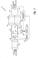
- CO 2 removal system 10 generally includes a first sorbent bed 12, a second sorbent bed 14, inlet passage 16, inlet valve 18, outlet passage 20, outlet valve 22, carbon dioxide passage 24, carbon dioxide valve 26, vacuum source 28, and controller 30.
- First and second sorbent beds 12 and 14 are thermally linked and heat is transferred between them. The heat extracted from one, adsorbing sorbent bed is used as energy to regenerate the other, desorbing sorbent bed.
- thermally linking first and second sorbent beds 12 and 14 increases the performance of CO 2 removal system 10 by approximately 30%.
- CO 2 removal system 10 may be used in any enclosed environment where removal of carbon dioxide is of importance, including, but not limited to, spacecraft.
- Inlet passage 16 introduces a process air stream into CO 2 removal system 10 from an enclosed environment.
- the process air stream generally includes water and carbon dioxide.
- Inlet valve 18 is connected to inlet passage 16 upstream of first and second sorbent beds 12 and 14 and is switchable between a first position and a second position to control the direction of the process air stream into either first sorbent bed 12 or second sorbent bed 14.
- Inlet valve 18 When inlet valve 18 is in the first position, the process air stream is allowed to flow only into first sorbent bed 12 and cannot enter second sorbent bed 14.
- Inlet valve 18 is in the second position, the process air stream is allowed to flow only into second sorbent bed 14 and cannot enter first sorbent bed 12.
- two inlet valves may also be used, depending on the configuration of inlet passage 16, to control flow of the process air stream into first and second sorbent beds 12 and 14 without departing from the intended scope of the present invention.
- First sorbent bed 12 and second sorbent bed 14 contain first sorbent 32 and second sorbent 34, respectively, and function to adsorb carbon dioxide in the process air stream.
- First sorbent bed 12 and second sorbent bed 14 are thermally linked to one another such that they may operate isothermally and at ambient temperature.
- First and second sorbent beds 12 and 14 may be thermally linked by direct physical contact or indirect physical contact.
- first and second sorbent beds 12 and 14 are indirectly connected through a heat exchanger or heat pipe. At any given time, one of sorbent beds 12, 14 is adsorbing carbon dioxide and the other sorbent bed 12, 14 is desorbing carbon dioxide.
- first and second sorbent beds 12 and 14 are constantly working in conjunction with one another. Once first sorbent bed 12 is fully saturated with carbon dioxide, inlet valve 18 will switch to the second position and second sorbent bed 14 will begin adsorbing carbon dioxide and first sorbent bed 12 will begin regenerating.
- Sorbents 32 and 34 of first and second sorbent bed 12 and 14, respectively may be any sorbent capable of adsorbing carbon dioxide, including, but not limited to: a 4A molecular sieve or a 5A molecular sieve.
- Thermal linking of first and second sorbent beds 12 and 14 provides a passive method of cooling first (adsorbing) sorbent bed 12 by transferring the exothermic heat created by the adsorption process to second sorbent bed 14. Because the adsorption process generates heat, first sorbent bed 12 needs to be cooled down. If the temperature of first sorbent bed 12 substantially increases above ambient temperature, adsorption will not occur. In contrast to the adsorption process, the desorption process is endothermic and requires energy to proceed. Thus, because the regeneration process is endothermic, second (desorbing) sorbent bed 14 will decrease in temperature, reaching equilibrium very quickly, with the rate of desorption decreasing as the temperature decreases.
- First and second sorbent beds 12 and 14 are thus thermally linked such that the heat generated from the adsorption process in first sorbent bed 12 is transferred to second sorbent bed 14 at a rate to maintain both the adsorption and the desorption processes at increased levels while still at ambient temperature.
- a temperature gradient is established between first and second sorbent beds 12 and 14 that allows for energy transfer between them.
- CO 2 removal system 10 thus operates by connecting first sorbent bed 12 and second sorbent bed 14 in a cyclic nature with one bed adsorbing and one bed desorbing.
- the heat transfer allows first and second sorbent beds 12 and 14 to operate substantially isothermally.
- Outlet passage 20 is connected to first and second sorbent beds 12 and 14 and expels cleansed air back into the environment.
- Outlet valve 22 is connected to outlet passage 20 downstream of first and second sorbent beds 12 and 14 and is switchable between a first position and a second position to allow cleansed process air back into the environment.
- the process air stream now cleansed of carbon dioxide is allowed to flow from first sorbent bed 12 back into the enclosed environment.
- the process air stream cannot flow from second sorbent bed 14 through outlet passage 20.
- outlet valve 22 is in the second position, the process air stream is allowed to flow from second sorbent bed 14 into the enclosed environment and cannot flow from first sorbent bed 12.
- outlet valve 22 When first sorbent bed 12 is adsorbing carbon dioxide, outlet valve 22 is in the first position and allows the cleansed process air stream to cycle back into the enclosed environment. Second sorbent bed 14, which is desorbing and may be carbon dioxide rich, is not allowed to expel into the environment. Although the sole figure depicts only one outlet valve, two outlet valves may also be used, depending on the configuration of outlet passage 20, to control flow of the process air stream back into the enclosed environment without departing from the intended scope of the present invention.
- Carbon dioxide passage 24 is connected to inlet passage 16 upstream of first and second sorbent beds 12 and 14.
- Carbon dioxide valve 26 is connected to carbon dioxide passage 24 and is positioned downstream of inlet valve 18.
- Carbon dioxide valve 26 is switchable between a first position and a second position to control the introduction of carbon dioxide enriched air into vacuum 28.
- first position When carbon dioxide valve 26 is in the first position, the process air stream from first sorbent bed 12 is allowed to flow from first sorbent bed 12 to vacuum 28.
- carbon dioxide valve 26 is in the second position, the process air stream from second sorbent bed 14 is allowed to flow from second sorbent bed 14 to vacuum 28.
- carbon dioxide valve 26 is in the second position and allows the carbon dioxide enriched stream to flow from second sorbent bed 14 through carbon dioxide passage 24 and into vacuum 28.
- first sorbent bed 12 is adsorbing carbon dioxide
- second sorbent bed 14 is desorbing carbon dioxide
- carbon dioxide valve 26 is in the second position and allows the carbon dioxide enriched stream to flow from second sorbent bed 14 through carbon dioxide passage 24 and into vacuum 28.
- two carbon dioxide valves may also be used, depending on the configuration of carbon dioxide passage 24, to control the flow of a carbon dioxide enriched stream to vacuum 28 without departing from the intended scope of the present invention.
- Vacuum 28 is connected to carbon dioxide passage 24 and reduces the pressure of first and second sorbent beds 12 and 14 to draw and expel the carbon dioxide enriched stream from first and second sorbent beds 12 and 14.
- vacuum reduces the pressure of first and second sorbent beds 12 and 14 to less than approximately 1 millimeter of mercury (0.133 kilopascals). The rate of desorption of the desorbing bed thus depends in part on the pressure at which vacuum 28 is running. The lower the pressure, the greater the efficiency of desorption.
- the enclosed environment is a spacecraft and vacuum 28 is a space vacuum, expelling the contaminated stream into space. In this case, the space vacuum runs at ambient pressure and expands to vacuum because of the close proximity of the vacuum of space.
- vacuum 28 includes a compressor and a vacuum pump. The compressor lowers the pressure in desorbing second sorbent bed 14 to a level that allows regeneration of second sorbent bed 14.
- Controller 30 is connected to inlet valve 18, outlet valve 22, and carbon dioxide valve 26 and switches valves 18, 22, and 26 between the first and second positions. Controller 30 determines which sorbent bed 12, 14 is adsorbing and which sorbent bed 12, 14 is desorbing and positions valves 18, 22, and 26 accordingly. When first sorbent bed 12 is adsorbing the carbon dioxide, controller 30 positions inlet valve 18 and outlet valve 22 in the first position and carbon dioxide valve 26 in the second position. When second sorbent bed 14 is adsorbing, controller 30 positions inlet valve 18 and outlet valve 22 in the second position and carbon dioxide valve 26 in the first position.
- inlet valve 18 and outlet valve 22 are initially in the first position with the process air stream flowing through first sorbent bed 12 and carbon dioxide valve 26 is initially in the second position with carbon dioxide enriched air from second sorbent bed 14 flowing out to the vacuum.
- CO 2 removal system 10 then operates as a batch process until first sorbent bed 12 is loaded with carbon dioxide and second sorbent bed 14 is regenerated and essentially free of carbon dioxide.
- inlet valve 18 and outlet valve 22 are switched to the second position to allow the process air stream to flow into second sorbent bed 14 and out to the environment.
- Carbon dioxide valve 26 is switched to the first position to allow first sorbent bed 12 to desorb the carbon dioxide into vacuum 28.
- First sorbent bed 12 then desorbs and second sorbent bed 14 adsorbs until second sorbent bed 14 becomes fully loaded with carbon dioxide and first sorbent bed 12 is regenerated.
- CO 2 removal system 10 continues to operate in this cyclic manner, with first and second sorbent beds 12 and 14 alternating between the adsorption process and the desorption process. Similarly, the direction of heat transfer is also cyclic.
- CO 2 removal system 10 may also optionally include third sorbent bed 36 positioned upstream of first and second sorbent beds 12 and 14.
- Third sorbent bed 36 includes third sorbent or dessicant 38 for removing any water from the process air stream before the process air stream enters first and second sorbent beds 12 and 14.
- the process air stream typically has a relative humidity of between approximately 30% and approximately 70%.
- Water can poison sorbents 32 and 34 by displacing the adsorbed carbon dioxide in sorbent beds 12 and 14.
- third sorbent bed 36 is positioned upstream of first and second sorbent beds 12 and 14.
- third sorbent 38 is a 13X molecular sieve.
- third sorbent bed 36 is saturated with water, the water may be desorbed from third sorbent bed 36 using heat in combination with vacuum 28 or a sweep gas.
- the heat may be supplied by any means known in the art, including heating rods installed within third sorbent bed 36 or by thermally linking third sorbent bed 36 with another sorbent bed.
- third sorbent bed 36 is connected to vacuum 28 by water valve 40, which is controlled by controller 30.
- Water valve 40 is switchable between a first position (closed) and a second (open) position. When water valve 40 is in the first position, third sorbent bed 36 is not connected to vacuum 28 and water is not removed from third sorbent bed 36.
- CO 2 removal system 10 may also include two sorbent beds for removing water working in conjunction with one another, such that one bed is adsorbing water and the other bed is desorbing water.
- the two beds may be thermally linked with the adsorbing sorbent bed transferring heat to the desorbing sorbent bed, similar to the process discussed for first and second sorbent beds 12 and 14.
- there may optionally be two water valves for controlling the flow of water to vacuum 28.
- the sweep gas may be any gas that does not contain water or carbon dioxide and must have a lower partial pressure than the partial pressure at which the water is being adsorbed in order to provide the driving force needed to regenerate third sorbent bed 36.
- the sweep gas may be the effluent leaving the sorbent bed that is adsorbing the carbon dioxide.
- the effluent functions efficiently as a sweep gas because it is dry and at an elevated temperature due to the exothermic adsorbing process.
- the water may be purged from third sorbent bed 36 using heated gas that is returned to the cabin to be dried by a condensing heat exchanger.
- third sorbent bed 36 is optional and is not required for the operation of CO 2 removal system 10. For example, if carbon dioxide is being removed in a dry atmosphere, third sorbent bed 36 would not be needed.
- the carbon dioxide removal system includes two thermally linked sorbent beds.
- the sorbent beds contain molecular sieves for adsorbing carbon dioxide from a process air stream. At any given time, one of the sorbent beds is adsorbing carbon dioxide from the process air stream and the other sorbent bed is regenerating by desorbing the carbon dioxide adsorbed from the process air stream.
- a plurality of valves switch positions such that the sorbent beds switch between adsorbing and desorbing.
- the sorbent beds are cyclic with one bed adsorbing and one bed desorbing.
- the sorbent beds of the carbon dioxide removal system thus operates substantially isothermally, maintains the carbon dioxide removal system at approximately ambient temperature, and provides a portion of the energy required to run the desorption process.
Landscapes
- Chemical & Material Sciences (AREA)
- Engineering & Computer Science (AREA)
- Analytical Chemistry (AREA)
- General Chemical & Material Sciences (AREA)
- Oil, Petroleum & Natural Gas (AREA)
- Chemical Kinetics & Catalysis (AREA)
- Separation Of Gases By Adsorption (AREA)
- Carbon And Carbon Compounds (AREA)
- Treating Waste Gases (AREA)
- Solid-Sorbent Or Filter-Aiding Compositions (AREA)
Applications Claiming Priority (1)
| Application Number | Priority Date | Filing Date | Title |
|---|---|---|---|
| US11/710,730 US7736416B2 (en) | 2007-02-26 | 2007-02-26 | Thermally linked molecular sieve beds for CO2 removal |
Publications (3)
| Publication Number | Publication Date |
|---|---|
| EP1964601A2 true EP1964601A2 (de) | 2008-09-03 |
| EP1964601A3 EP1964601A3 (de) | 2010-03-24 |
| EP1964601B1 EP1964601B1 (de) | 2014-01-22 |
Family
ID=39495826
Family Applications (1)
| Application Number | Title | Priority Date | Filing Date |
|---|---|---|---|
| EP07255088.2A Ceased EP1964601B1 (de) | 2007-02-26 | 2007-12-31 | Thermisch verbundene Molekularsiebbetten zur CO2-Entfernung |
Country Status (3)
| Country | Link |
|---|---|
| US (1) | US7736416B2 (de) |
| EP (1) | EP1964601B1 (de) |
| JP (1) | JP2008207177A (de) |
Cited By (6)
| Publication number | Priority date | Publication date | Assignee | Title |
|---|---|---|---|---|
| CN102032721A (zh) * | 2010-12-16 | 2011-04-27 | 中国科学院广州能源研究所 | 新型的蒸发器和冷凝器以及吸附式制冷机 |
| EP2468384A1 (de) * | 2010-12-22 | 2012-06-27 | Hamilton Sundstrand Space Systems International, Inc. | Verfahren und System zum Entfernen von Kohlendioxid |
| WO2013028815A1 (en) * | 2011-08-24 | 2013-02-28 | Corning Incorporated | Thermally integrated adsorption-desorption systems and methods |
| EP3656456A1 (de) * | 2018-11-21 | 2020-05-27 | Hamilton Sundstrand Corporation | Kohlenstoffdioxidadsorber für flugzeug |
| EP2767323B1 (de) * | 2013-02-14 | 2021-12-08 | The Boeing Company | System und Verfahren zum Sammeln von Kohlendioxid unter Verwendung einer dielektrischen Heizung |
| EP4563213A4 (de) * | 2022-09-01 | 2025-12-17 | Mitsubishi Heavy Ind Ltd | Vorrichtung und verfahren zur rückgewinnung von kohlendioxid |
Families Citing this family (34)
| Publication number | Priority date | Publication date | Assignee | Title |
|---|---|---|---|---|
| CA2770880C (en) * | 2009-08-24 | 2018-10-16 | Cellera, Inc. | Systems and methods of securing immunity to air co2 in alkaline fuel cells |
| US8128735B1 (en) * | 2009-10-21 | 2012-03-06 | The United States Of America As Represented By The United States Department Of Energy | Process for CO2 capture using zeolites from high pressure and moderate temperature gas streams |
| US20120006193A1 (en) * | 2010-07-09 | 2012-01-12 | Subir Roychoudhury | Adsorption-desorption apparatus and process |
| CN102463017A (zh) * | 2010-11-09 | 2012-05-23 | 江苏中川通大环保设备制造有限公司 | 换热吸附式气体吸附分离回收的方法及装置 |
| CN103492046B (zh) | 2011-01-20 | 2015-08-26 | 沙特阿拉伯石油公司 | 将废热用于co2的车上回收和存储的可逆固体吸附方法和系统 |
| EP2665808B1 (de) | 2011-01-20 | 2016-12-07 | Saudi Arabian Oil Company | Bordeigene rückgewinnung und lagerung von co2 aus kraftfahrzeugabgasen |
| WO2012100157A1 (en) | 2011-01-20 | 2012-07-26 | Saudi Arabian Oil Company | Direct densification method and system utilizing waste heat for on-board recovery and storage of co2 from motor vehicle internal combustion engine exhaust gases |
| US9371755B2 (en) | 2011-01-20 | 2016-06-21 | Saudi Arabian Oil Company | Membrane separation method and system utilizing waste heat for on-board recovery and storage of CO2 from motor vehicle internal combustion engine exhaust gases |
| US8858889B2 (en) | 2011-04-11 | 2014-10-14 | Hamilton Sundstrand Space Systems International, Inc. | Contaminate control device |
| WO2013012622A1 (en) | 2011-07-18 | 2013-01-24 | Carrier Corporation | Regenerative scrubber system with single flow diversion actuator |
| US9341408B2 (en) | 2011-07-18 | 2016-05-17 | Carrier Corporation | Scrubber system with moving adsorbent bed |
| DK2734048T3 (en) | 2011-07-18 | 2017-06-19 | Carrier Corp | MANAGING ATMOSPHERE IN A CLOSED ENVIRONMENT. |
| US10118122B2 (en) * | 2011-08-29 | 2018-11-06 | The Boeing Company | CO2 collection methods and systems |
| US8702851B2 (en) | 2012-03-02 | 2014-04-22 | Hamilton Sundstrand Space Systems International, Inc. | Heat exchanger |
| US8696802B2 (en) | 2012-03-02 | 2014-04-15 | Hamilton Sunstrand Space Systems International, Inc. | Heat exchanger |
| US9205357B2 (en) | 2012-03-29 | 2015-12-08 | The Boeing Company | Carbon dioxide separation system and method |
| US9156703B2 (en) | 2012-03-30 | 2015-10-13 | The Boeing Company | System and method for producing carbon dioxide |
| US9103549B2 (en) | 2012-08-23 | 2015-08-11 | The Boeing Company | Dual stream system and method for producing carbon dioxide |
| US9777628B2 (en) | 2012-08-23 | 2017-10-03 | The Boeing Company | System and method for processing greenhouse gases |
| US9073001B2 (en) | 2013-02-14 | 2015-07-07 | The Boeing Company | Monolithic contactor and associated system and method for collecting carbon dioxide |
| FR3003183A1 (fr) * | 2013-03-13 | 2014-09-19 | Eblatas | Recycleur a adsorption de co2. |
| JP5858948B2 (ja) * | 2013-03-28 | 2016-02-10 | Jfeスチール株式会社 | 吸着塔およびガス分離装置 |
| JP6238277B2 (ja) * | 2013-06-04 | 2017-11-29 | 株式会社Ihiエアロスペース | 二酸化炭素除去装置 |
| DE102013223342A1 (de) * | 2013-11-15 | 2015-05-21 | Thyssenkrupp Marine Systems Gmbh | Unterseeboot mit einer CO2-Bindeeinrichtung |
| EP2977093B1 (de) * | 2014-07-25 | 2021-05-05 | Airbus Defence and Space GmbH | Verfahren zu einer Abtrennung von Kohlendioxid aus Atemluft eines U-Boots |
| WO2017165974A1 (en) | 2016-03-31 | 2017-10-05 | Inventys Thermal Technologies Inc. | Adsorptive gas separation process and system |
| JP6957497B2 (ja) | 2016-03-31 | 2021-11-02 | スヴァンテ インコーポレイテッド | 再生のために蒸気を使用する吸着ガス分離 |
| JP2022100893A (ja) * | 2020-12-24 | 2022-07-06 | 株式会社デンソー | 二酸化炭素回収システム |
| EP4301491A4 (de) * | 2021-03-04 | 2024-11-20 | Echeneidae Inc. | System und verfahren zur mobilen kohlenstoffabscheidung |
| JP7394469B2 (ja) * | 2021-06-14 | 2023-12-08 | 龍祥 權 | 二酸化炭素回収装置及び二酸化炭素回収システム |
| US11654393B2 (en) * | 2021-08-29 | 2023-05-23 | Carbon Capture Inc. | Temperature vacuum swing adsorption process suited for carbon capture to regenerate sorbents using the CO2 product gas as the heat transfer medium |
| CA3249434A1 (en) * | 2022-01-26 | 2023-08-03 | Battelle Memorial Institute | SYSTEM AND METHOD FOR DIRECT CAPTURE OF AIR, WATER AND CO2 |
| US20230264138A1 (en) * | 2022-02-22 | 2023-08-24 | Battelle Memorial Institute | System and method for direct air capture of water and co2 |
| US12491467B1 (en) * | 2025-05-12 | 2025-12-09 | Provocative Science Holdings, Inc. | Carbon capture systems and methods of use |
Citations (1)
| Publication number | Priority date | Publication date | Assignee | Title |
|---|---|---|---|---|
| US6364938B1 (en) | 2000-08-17 | 2002-04-02 | Hamilton Sundstrand Corporation | Sorbent system and method for absorbing carbon dioxide (CO2) from the atmosphere of a closed habitable environment |
Family Cites Families (17)
| Publication number | Priority date | Publication date | Assignee | Title |
|---|---|---|---|---|
| US2545194A (en) | 1945-11-14 | 1951-03-13 | Allan P Colburn | Adsorption process for removal of carbon dioxide from the atmosphere of a submarine |
| US3100685A (en) * | 1959-10-30 | 1963-08-13 | Arnold Equipment Corp | Method of recovering carbon dioxide |
| US4005708A (en) | 1974-04-29 | 1977-02-01 | A-T-O Inc. | Apparatus for endothermal absorption of carbon dioxide |
| JPS5953201B2 (ja) * | 1979-12-18 | 1984-12-24 | 松下電器産業株式会社 | 水素ガスの精製方法 |
| US4822383A (en) | 1987-04-30 | 1989-04-18 | United Technologies Corporation | Method and apparatus for removing carbon dioxide from air |
| US4810266A (en) | 1988-02-25 | 1989-03-07 | Allied-Signal Inc. | Carbon dioxide removal using aminated carbon molecular sieves |
| GB8812263D0 (en) | 1988-05-24 | 1988-06-29 | Boc Group Plc | Separation of gaseous mixtures |
| US5110569A (en) | 1990-01-19 | 1992-05-05 | The Boc Group, Inc. | Low temperature purification of gases |
| US5281254A (en) | 1992-05-22 | 1994-01-25 | United Technologies Corporation | Continuous carbon dioxide and water removal system |
| US5376614A (en) | 1992-12-11 | 1994-12-27 | United Technologies Corporation | Regenerable supported amine-polyol sorbent |
| US5876488A (en) | 1996-10-22 | 1999-03-02 | United Technologies Corporation | Regenerable solid amine sorbent |
| ATE349347T1 (de) | 1999-11-17 | 2007-01-15 | Domnick Hunter Ltd | Luftbehandlungsystem |
| US6755892B2 (en) | 2000-08-17 | 2004-06-29 | Hamilton Sundstrand | Carbon dioxide scrubber for fuel and gas emissions |
| US6692545B2 (en) * | 2001-02-09 | 2004-02-17 | General Motors Corporation | Combined water gas shift reactor/carbon dioxide adsorber for use in a fuel cell system |
| US6630012B2 (en) * | 2001-04-30 | 2003-10-07 | Battelle Memorial Institute | Method for thermal swing adsorption and thermally-enhanced pressure swing adsorption |
| CA2388423C (en) | 2002-05-31 | 2005-03-22 | Co2 Solution Inc. | A ventilation system for an enclosure in which people live and a method thereof |
| US6709483B1 (en) | 2002-10-07 | 2004-03-23 | Hamilton Sundstrand Corp. | Regenerative carbon dioxide (CO2) removal system |
-
2007
- 2007-02-26 US US11/710,730 patent/US7736416B2/en active Active
- 2007-12-31 EP EP07255088.2A patent/EP1964601B1/de not_active Ceased
-
2008
- 2008-02-22 JP JP2008041536A patent/JP2008207177A/ja active Pending
Patent Citations (1)
| Publication number | Priority date | Publication date | Assignee | Title |
|---|---|---|---|---|
| US6364938B1 (en) | 2000-08-17 | 2002-04-02 | Hamilton Sundstrand Corporation | Sorbent system and method for absorbing carbon dioxide (CO2) from the atmosphere of a closed habitable environment |
Cited By (10)
| Publication number | Priority date | Publication date | Assignee | Title |
|---|---|---|---|---|
| CN102032721A (zh) * | 2010-12-16 | 2011-04-27 | 中国科学院广州能源研究所 | 新型的蒸发器和冷凝器以及吸附式制冷机 |
| CN102032721B (zh) * | 2010-12-16 | 2013-07-31 | 中国科学院广州能源研究所 | 包括蒸发器和冷凝器的吸附式制冷机 |
| EP2468384A1 (de) * | 2010-12-22 | 2012-06-27 | Hamilton Sundstrand Space Systems International, Inc. | Verfahren und System zum Entfernen von Kohlendioxid |
| WO2013028815A1 (en) * | 2011-08-24 | 2013-02-28 | Corning Incorporated | Thermally integrated adsorption-desorption systems and methods |
| US8858690B2 (en) | 2011-08-24 | 2014-10-14 | Corning Incorporated | Thermally integrated adsorption-desorption systems and methods |
| US9138676B2 (en) | 2011-08-24 | 2015-09-22 | Corning Incorporated | Thermally integrated adsorption-desorption systems and methods |
| EP2767323B1 (de) * | 2013-02-14 | 2021-12-08 | The Boeing Company | System und Verfahren zum Sammeln von Kohlendioxid unter Verwendung einer dielektrischen Heizung |
| EP3656456A1 (de) * | 2018-11-21 | 2020-05-27 | Hamilton Sundstrand Corporation | Kohlenstoffdioxidadsorber für flugzeug |
| US10981655B2 (en) | 2018-11-21 | 2021-04-20 | Hamilton Sundstrand Corporation | Carbon dioxide adsorber for aircraft |
| EP4563213A4 (de) * | 2022-09-01 | 2025-12-17 | Mitsubishi Heavy Ind Ltd | Vorrichtung und verfahren zur rückgewinnung von kohlendioxid |
Also Published As
| Publication number | Publication date |
|---|---|
| US20080202339A1 (en) | 2008-08-28 |
| JP2008207177A (ja) | 2008-09-11 |
| US7736416B2 (en) | 2010-06-15 |
| EP1964601B1 (de) | 2014-01-22 |
| EP1964601A3 (de) | 2010-03-24 |
Similar Documents
| Publication | Publication Date | Title |
|---|---|---|
| US7736416B2 (en) | Thermally linked molecular sieve beds for CO2 removal | |
| US11285438B2 (en) | Carbon dioxide separation recovery system and method | |
| EP2468384A1 (de) | Verfahren und System zum Entfernen von Kohlendioxid | |
| AU2019372694B2 (en) | Carbon dioxide separation recovery system and method | |
| JP2021133323A (ja) | ガス分離回収装置 | |
| EP2781249A1 (de) | Kohlendioxidabscheidungsausrüstung | |
| KR102473002B1 (ko) | 가스를 압축 및 건조하는 방법 및 장치 | |
| EP3656456A1 (de) | Kohlenstoffdioxidadsorber für flugzeug | |
| WO2017135468A1 (ja) | 二酸化炭素回収システム及び二酸化炭素分離回収システム | |
| US10315152B2 (en) | Method and system for pressure swing adsorption | |
| US20240139673A1 (en) | Method and apparatus for drying a process gas | |
| JPH04135611A (ja) | 炭酸ガス除去装置 | |
| JPH09122432A (ja) | 圧力スイング吸着法によるガス分離装置 | |
| JP7842136B2 (ja) | 二酸化炭素回収装置 | |
| EP4721840A1 (de) | Verfahren zur kontinuierlichen extraktion einer substanz aus einem fluid | |
| JP2026060177A (ja) | 二酸化炭素施用装置 | |
| CN120361671A (zh) | 二氧化碳回收装置 | |
| WO2025203438A1 (ja) | 二酸化炭素回収装置及び二酸化炭素回収方法 | |
| CN120679292A (zh) | 二氧化碳回收装置 | |
| JP2001252360A (ja) | 酸素濃縮装置 | |
| JP2007209900A (ja) | 成分濃縮分離装置および成分濃縮分離方法 | |
| JPH10202041A (ja) | 空質制御装置 | |
| OA18475A (en) | Method and apparatus for compressing and drying a gas | |
| JPH02284625A (ja) | 気体乾燥装置 |
Legal Events
| Date | Code | Title | Description |
|---|---|---|---|
| PUAI | Public reference made under article 153(3) epc to a published international application that has entered the european phase |
Free format text: ORIGINAL CODE: 0009012 |
|
| AK | Designated contracting states |
Kind code of ref document: A2 Designated state(s): AT BE BG CH CY CZ DE DK EE ES FI FR GB GR HU IE IS IT LI LT LU LV MC MT NL PL PT RO SE SI SK TR |
|
| AX | Request for extension of the european patent |
Extension state: AL BA HR MK RS |
|
| PUAL | Search report despatched |
Free format text: ORIGINAL CODE: 0009013 |
|
| AK | Designated contracting states |
Kind code of ref document: A3 Designated state(s): AT BE BG CH CY CZ DE DK EE ES FI FR GB GR HU IE IS IT LI LT LU LV MC MT NL PL PT RO SE SI SK TR |
|
| AX | Request for extension of the european patent |
Extension state: AL BA HR MK RS |
|
| 17P | Request for examination filed |
Effective date: 20100625 |
|
| 17Q | First examination report despatched |
Effective date: 20100730 |
|
| AKX | Designation fees paid |
Designated state(s): DE FR GB |
|
| GRAP | Despatch of communication of intention to grant a patent |
Free format text: ORIGINAL CODE: EPIDOSNIGR1 |
|
| INTG | Intention to grant announced |
Effective date: 20130731 |
|
| GRAS | Grant fee paid |
Free format text: ORIGINAL CODE: EPIDOSNIGR3 |
|
| GRAA | (expected) grant |
Free format text: ORIGINAL CODE: 0009210 |
|
| AK | Designated contracting states |
Kind code of ref document: B1 Designated state(s): DE FR GB |
|
| REG | Reference to a national code |
Ref country code: GB Ref legal event code: FG4D |
|
| REG | Reference to a national code |
Ref country code: DE Ref legal event code: R096 Ref document number: 602007034888 Country of ref document: DE Effective date: 20140306 |
|
| REG | Reference to a national code |
Ref country code: DE Ref legal event code: R097 Ref document number: 602007034888 Country of ref document: DE |
|
| PLBE | No opposition filed within time limit |
Free format text: ORIGINAL CODE: 0009261 |
|
| STAA | Information on the status of an ep patent application or granted ep patent |
Free format text: STATUS: NO OPPOSITION FILED WITHIN TIME LIMIT |
|
| 26N | No opposition filed |
Effective date: 20141023 |
|
| REG | Reference to a national code |
Ref country code: DE Ref legal event code: R097 Ref document number: 602007034888 Country of ref document: DE Effective date: 20141023 |
|
| REG | Reference to a national code |
Ref country code: DE Ref legal event code: R119 Ref document number: 602007034888 Country of ref document: DE |
|
| PG25 | Lapsed in a contracting state [announced via postgrant information from national office to epo] |
Ref country code: DE Free format text: LAPSE BECAUSE OF NON-PAYMENT OF DUE FEES Effective date: 20150701 |
|
| REG | Reference to a national code |
Ref country code: FR Ref legal event code: PLFP Year of fee payment: 9 |
|
| REG | Reference to a national code |
Ref country code: FR Ref legal event code: PLFP Year of fee payment: 10 |
|
| REG | Reference to a national code |
Ref country code: FR Ref legal event code: PLFP Year of fee payment: 11 |
|
| P01 | Opt-out of the competence of the unified patent court (upc) registered |
Effective date: 20230522 |
|
| PGFP | Annual fee paid to national office [announced via postgrant information from national office to epo] |
Ref country code: GB Payment date: 20231124 Year of fee payment: 17 |
|
| PGFP | Annual fee paid to national office [announced via postgrant information from national office to epo] |
Ref country code: FR Payment date: 20231122 Year of fee payment: 17 |
|
| GBPC | Gb: european patent ceased through non-payment of renewal fee |
Effective date: 20241231 |
|
| PG25 | Lapsed in a contracting state [announced via postgrant information from national office to epo] |
Ref country code: GB Free format text: LAPSE BECAUSE OF NON-PAYMENT OF DUE FEES Effective date: 20241231 |
|
| PG25 | Lapsed in a contracting state [announced via postgrant information from national office to epo] |
Ref country code: FR Free format text: LAPSE BECAUSE OF NON-PAYMENT OF DUE FEES Effective date: 20241231 |