EP1963808B1 - Vorrichtung zur lastenmessung - Google Patents
Vorrichtung zur lastenmessung Download PDFInfo
- Publication number
- EP1963808B1 EP1963808B1 EP06841973A EP06841973A EP1963808B1 EP 1963808 B1 EP1963808 B1 EP 1963808B1 EP 06841973 A EP06841973 A EP 06841973A EP 06841973 A EP06841973 A EP 06841973A EP 1963808 B1 EP1963808 B1 EP 1963808B1
- Authority
- EP
- European Patent Office
- Prior art keywords
- air gap
- outer part
- inner part
- electrode
- thermal expansion
- Prior art date
- Legal status (The legal status is an assumption and is not a legal conclusion. Google has not performed a legal analysis and makes no representation as to the accuracy of the status listed.)
- Not-in-force
Links
Images



Classifications
-
- G—PHYSICS
- G01—MEASURING; TESTING
- G01L—MEASURING FORCE, STRESS, TORQUE, WORK, MECHANICAL POWER, MECHANICAL EFFICIENCY, OR FLUID PRESSURE
- G01L5/00—Apparatus for, or methods of, measuring force, work, mechanical power, or torque, specially adapted for specific purposes
- G01L5/0009—Force sensors associated with a bearing
- G01L5/0014—Force sensors associated with a bearing by using capacitive sensors
-
- F—MECHANICAL ENGINEERING; LIGHTING; HEATING; WEAPONS; BLASTING
- F16—ENGINEERING ELEMENTS AND UNITS; GENERAL MEASURES FOR PRODUCING AND MAINTAINING EFFECTIVE FUNCTIONING OF MACHINES OR INSTALLATIONS; THERMAL INSULATION IN GENERAL
- F16C—SHAFTS; FLEXIBLE SHAFTS; ELEMENTS OR CRANKSHAFT MECHANISMS; ROTARY BODIES OTHER THAN GEARING ELEMENTS; BEARINGS
- F16C27/00—Elastic or yielding bearings or bearing supports, for exclusively rotary movement
- F16C27/04—Ball or roller bearings, e.g. with resilient rolling bodies
-
- F—MECHANICAL ENGINEERING; LIGHTING; HEATING; WEAPONS; BLASTING
- F16—ENGINEERING ELEMENTS AND UNITS; GENERAL MEASURES FOR PRODUCING AND MAINTAINING EFFECTIVE FUNCTIONING OF MACHINES OR INSTALLATIONS; THERMAL INSULATION IN GENERAL
- F16C—SHAFTS; FLEXIBLE SHAFTS; ELEMENTS OR CRANKSHAFT MECHANISMS; ROTARY BODIES OTHER THAN GEARING ELEMENTS; BEARINGS
- F16C35/00—Rigid support of bearing units; Housings, e.g. caps, covers
- F16C35/04—Rigid support of bearing units; Housings, e.g. caps, covers in the case of ball or roller bearings
- F16C35/042—Housings for rolling element bearings for rotary movement
- F16C35/045—Housings for rolling element bearings for rotary movement with a radial flange to mount the housing
-
- G—PHYSICS
- G01—MEASURING; TESTING
- G01L—MEASURING FORCE, STRESS, TORQUE, WORK, MECHANICAL POWER, MECHANICAL EFFICIENCY, OR FLUID PRESSURE
- G01L1/00—Measuring force or stress, in general
- G01L1/14—Measuring force or stress, in general by measuring variations in capacitance or inductance of electrical elements, e.g. by measuring variations of frequency of electrical oscillators
- G01L1/142—Measuring force or stress, in general by measuring variations in capacitance or inductance of electrical elements, e.g. by measuring variations of frequency of electrical oscillators using capacitors
-
- F—MECHANICAL ENGINEERING; LIGHTING; HEATING; WEAPONS; BLASTING
- F16—ENGINEERING ELEMENTS AND UNITS; GENERAL MEASURES FOR PRODUCING AND MAINTAINING EFFECTIVE FUNCTIONING OF MACHINES OR INSTALLATIONS; THERMAL INSULATION IN GENERAL
- F16C—SHAFTS; FLEXIBLE SHAFTS; ELEMENTS OR CRANKSHAFT MECHANISMS; ROTARY BODIES OTHER THAN GEARING ELEMENTS; BEARINGS
- F16C19/00—Bearings with rolling contact, for exclusively rotary movement
- F16C19/02—Bearings with rolling contact, for exclusively rotary movement with bearing balls essentially of the same size in one or more circular rows
- F16C19/04—Bearings with rolling contact, for exclusively rotary movement with bearing balls essentially of the same size in one or more circular rows for radial load mainly
- F16C19/06—Bearings with rolling contact, for exclusively rotary movement with bearing balls essentially of the same size in one or more circular rows for radial load mainly with a single row or balls
-
- F—MECHANICAL ENGINEERING; LIGHTING; HEATING; WEAPONS; BLASTING
- F16—ENGINEERING ELEMENTS AND UNITS; GENERAL MEASURES FOR PRODUCING AND MAINTAINING EFFECTIVE FUNCTIONING OF MACHINES OR INSTALLATIONS; THERMAL INSULATION IN GENERAL
- F16C—SHAFTS; FLEXIBLE SHAFTS; ELEMENTS OR CRANKSHAFT MECHANISMS; ROTARY BODIES OTHER THAN GEARING ELEMENTS; BEARINGS
- F16C19/00—Bearings with rolling contact, for exclusively rotary movement
- F16C19/52—Bearings with rolling contact, for exclusively rotary movement with devices affected by abnormal or undesired conditions
- F16C19/522—Bearings with rolling contact, for exclusively rotary movement with devices affected by abnormal or undesired conditions related to load on the bearing, e.g. bearings with load sensors or means to protect the bearing against overload
Definitions
- the present invention relates to the field of housings for bearings, in particular for rolling bearings, for detecting the load applied to said bearing in operation or at a standstill.
- the documents DE 2729699 and US 2002/0026839 describe housing arrangements for bearings.
- the housings are provided with strain gauges in order to allow measurement of the loads applied to the bearings by measuring the variations of stress in certain parts of the housing.
- Such devices use strain gauges whose implementation is relatively delicate and often not compatible with mass production at reasonable costs.
- the document FR 2 863 706 discloses a load metering device on a washing machine bearing, comprising capacitors provided with an insulator whose thickness may vary depending on the load and a means for measuring the capacity of the capacitor, the capacitance being representative of the load applied perpendicularly to the electrodes, one of the electrodes being formed by one of the rings of the bearing.
- This device works satisfactorily.
- the sensing zones comprise parts or parts of parts whose coefficients of thermal expansion are different. As a result, during temperature variations, differential expansions in the zone of detection likely to cause variations of gap which will disturb the measurements made because they will be interpreted as variations of load. This phenomenon is even more penalizing that the desired accuracy is high.
- the object of the invention is in particular to remedy the defects mentioned above.
- the invention aims at a reliable and accurate load measurement, based on the measurement of displacements due to elastic deformations of the housing under the load, regardless of the temperature.
- Another object of the invention is to provide a device for measuring charge which is very insensitive to temperature variations.
- the device for detecting a load comprises a test body provided with an external part and an internal part, the inner part being connected to the external part by at least two elastically deformable connecting elements under the effect of the applied load, the outer and inner parts being separated by an air gap between electrodes supported by the outer part and the inner part.
- the detection of the load is determined by the measurement of the displacements between the internal part and the external part at the gap.
- the inner portion comprises an annular shaped body provided with a bore, and two diametrically opposite detection portions, cooperating with corresponding portions of the outer portion with the gap.
- the air gap remains substantially constant when the temperature varies.
- the thicknesses and coefficients of thermal expansion of the portions of the test body capable of varying the air gap and electrodes are determined such that a positive variation of at least a portion of the test body that can vary. the gap and / or an electrode is compensated by a variation negative of at least another portion of the test body may vary the gap and / or another electrode.
- the inner part may be movable relative to the outer part.
- the sum of the products of the thickness by the coefficient of thermal expansion of the elements producing a positive variation of the gap is substantially equal to the sum of the products of the thickness by the coefficient of thermal expansion of the elements. producing a negative variation of the gap. This results in a compensation of the variations of the gap.
- the device being symmetrical with respect to a plane passing through a geometric axis of said device, the product of the coefficient of thermal expansion of the external part and the distance between the plane and a face of the external part is equal. to the sum of the product of the coefficient of thermal expansion of the inner part and the distance between the plane and a face of the inner part and the product of the thermal expansion coefficient of a first electrode and the thickness of the electrode .
- the gap can be substantially constant over a range of temperatures, for example from 0 to + 50 ° C in the field of household appliances.
- the outer portion and the inner portion may be made of the same material.
- the outer portion and a detection portion of the inner portion are made of different materials, the detection portion of the inner portion forming an electrode and the outer portion forming another electrode.
- the device comprises a pair of electrodes.
- the device may include two pairs of electrodes for differential measurement.
- the proof body is monoblock.
- the applied load detection system comprises a movable detection portion rigidly connected to the inner portion and thus movable under the action of the load.
- the detection portion of the inner portion is decoupled from the outer portion with respect to which said sensing portion can move without contact, the outer portion comprising an outer sensing portion facing the moving sensing portion to form at least one an air gap with the mobile detection portion.
- the applied load sensing system also includes sensing means for measuring the displacements of the inner portion through variations of the gap between the fixed and movable sensing portions.
- the terms "fixed” and “mobile” are here understood in the relative sense.
- the detection portions may be disposed near an axial plane of symmetry substantially perpendicular to the load to be measured.
- the device may comprise at least two planes of symmetry perpendicular to each other.
- the outer portion, the inner portion and the connecting elements form a one-piece assembly.
- Said one-piece assembly can be obtained in large series by molding a metal alloy or a synthetic material having mechanical properties, including elasticity, desired for the application in question.
- the same mold provided for a one-piece assembly can be used for manufacturing monoblock sets of features different elastics, depending on the chosen composition of the material, which is particularly economical.
- the fixed detection portion is attached to the inside of the outer portion.
- the fixed detection portion is integral with the outer portion.
- the outer portion may comprise a body comprising two portions each provided with a groove in which there protrudes a detection portion of the inner portion.
- the housing device is provided with a test body 1 comprising an outer portion 2 and an inner portion 3 separated by a space 4.
- the outer 2 and inner 3 portions are delimited by two radial planes.
- the inner part 3 is provided with a bore, in which is disposed a rolling bearing 5 mounted on a shaft 6.
- the outer part 2 is intended to be disposed in a mechanical assembly, for example a housing, a frame or a support , not shown.
- the rolling bearing 5 comprises an outer ring 7, an inner ring 8, a row of rolling elements 9, here balls, held at regular circumferential spacings by a cage 10.
- the rolling elements 9 are arranged between an inner raceway of the outer ring 7 and an outer race of the inner ring 8.
- the rolling bearing 5 is defined by the axial outer surface of the outer ring 7, the bore of the inner ring 8 and the radial end faces of the rings.
- outer 7 and inner 8 which pass from one side and the other of the rolling elements 9, each by a radial plane, coincident on one side with the radial plane delimiting the test body 1.
- the rings 7 and 8 are here made of metal, for example steel, and the raceways are machined with removal of chips.
- the shaft 6 is able to undergo a radial load oriented in the direction of the arrow 11. Said load causes a slight radial displacement of the shaft 6, the rolling bearing 5 and the inner portion 3 relative to the outer portion 2.
- the structure of Test Body 1 is discussed in more detail on the Figures 2 and 3 .
- the inner portion 3 comprises a ring-shaped body delimited axially by the aforementioned radial planes and having a substantially constant thickness.
- the inner part 3 also comprises two mobile detection portions 13, in the form of diametrically opposed ears extending outwardly from the body 12. In the example illustrated, the mobile detection portions 13 have an axial length substantially equal to that of the body 12 and the test body 1.
- the inner part 3 also comprises a flange 14, in the form of a plurality of segments separated from each other and circumferentially regularly distributed, flush with the one radial planes delimiting the test body 1 and extending radially inwards from the bore 12a of the annular body 12.
- the flange 14 serves as axial abutment to the rolling bearing 5, when mounting said bearing to bearing 5 in the housing, and thus ensures axial positioning of the bearing to rolling 5.
- the mobile detection portions 13 and the flange 14 are monoblock with the body 12.
- the outer portion 2 comprises a body 15, adapted to be mounted in the bore of a housing or the like.
- the body 15 comprises two thick portions 16, symmetrical with respect to a plane passing through the axis of the test body 1, and two portions 17 of small radial thickness, each in the shape of a roof, having two panels 17a and 17b, joining in a plane of symmetry passing through the axis of the test body 1.
- the sections 17a and 17b have a substantially constant thickness, except at their junction, because of a wide connection fillet, on the side concave, that is to say on the inside.
- the sections 17a and 17b are connected to the thick portions 16 opposite the roof edge.
- Each thick portion 16 comprises a groove 18 extending axially over the entire length of the test body 1, and in which the movable detection portion 13 of the inner portion 3 projects.
- the thick portion 16 extends radially towards the inside. interior to form jaw-shaped outer sensing portions 19 and 20 surrounding the movable sensing portion 13.
- the test body 1 is completed by a connecting portion 21 provided with four arms 22, of rounded and deformable shape, connected to the outer portion 3, substantially at the connection between the thick portion 16 and the thin portion. 17, and connecting to the inner portion 3 to the right of the junction between the sections 17a and 17b of the thin portion 17.
- two symmetrical arms 22 are also connected to one another. Between the aforementioned connections, the arms 22 have a rounded shape between the inner portion 3 and the thin portion 17 and extend axially over all or part of the length of the test body 1.
- the outer portion 2, the inner portion 3 and the connecting portion 21 are in one piece and can be made by molding a conductive synthetic material, or by molding a metal, for example an aluminum alloy.
- Test body 1 is symmetrical with respect to two perpendicular planes passing through the axis of said test body 1, one of the planes passing through the junction between the panels 17a and 17b, and the other plane passing through the mobile detection portions 13, which are thus angularly offset by 180 °.
- the air gap 25 between the mobile detection portion 13 and the fixed detection portion 19 is equal to the gap 26 between the mobile detection portion 13 and the fixed detection portion 20, and this both sides of the test body 1.
- a radial load is applied, for example in the direction 11, that is to say vertically downwards, the outer part 2 remains substantially immobile, while the inner portion 3 moves in the direction of the applied load.
- the air gap 25 between the mobile detection portion 13 and the fixed detection portion 19 decreases, and the air gap 26 between the mobile detection portion 13 and the fixed detection portion 20 increases.
- the connecting arms 22 deform downwards, without substantially deforming the inner portion 3 due, on the one hand, to its annular structure, and on the other hand, to the symmetry of the test body 1 as a whole, and without also substantially deforming the outer portion 2, in particular because of the large thickness of the thick portion 16, a slight deformation of the thin portion 17 can be tolerated without impairing the measurement.
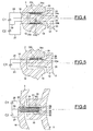
- each electrode 23, 24 comprises an insulating layer 23a, 24a, for example made of synthetic material, a conductive layer 23b, 24b disposed on the side of the mobile detection portion 13, and an inner conductive layer 23c, 24c or guard electrode forming an electromagnetic shield. More particularly, each electrode 23, 24 may be made by a printed circuit board portion, whose support forms the insulating layer 23a, 24a, and whose metal conductive circuits form the conductive layers 23b, 24b and 23c, 24c. Electrodes 23 and 24 can thus be manufactured at low cost, then fixed, for example by gluing, on the edges of the groove 18.
- An electrical circuit comprising two capacitors of varying capacitances, C1 and C2, the capacitor C1 being formed by the conductive layer 24b and the mobile detection portion 13 separated by the gap 26, and the capacitor C2 being formed by the layer conductor 23b of the electrode 23, and the mobile detection portion 13 separated by the gap 25.
- each capacitor C1, C2 is directly representative of the value of the air gaps 25 and 26 and, consequently, of the load applied to the internal part of the test body 1, insofar as the application of the charge causes moving the movable detection portion 13 relative to the electrodes 23 and 24 which remain fixed.
- Each electrode 23, 24 is provided with an output wire 27, 28, and the conductive mass of the test body 1 is connected by a wire 29 thus allowing the exploitation of the output signals.
- the device is devoid of electrode 23. Only the capacitance C1 then varies according to the gap between the mobile detection portion 13 and the electrode 24. The gap between the mobile detection portion 13 and the edge of the groove 18 opposite the electrode 24 remains without influence, insofar as the two surfaces are equipotential thanks to the integral embodiment of conductive material of the outer portion 2, the inner portion 3 and the connecting portion 21 of the body test 1.
- the electrical diagram is similar to that of the figure 4 , with two capacitors C1 and C2.
- the inner portion 3 comprises two movable detection portions 30 and 31, projecting radially outwardly, defining between them an axially elongated groove 32.
- the outer portion 2 comprises a tongue 33 directed radially inwards, disposed in the groove 32 between the mobile detection portions 30 and 31.
- the tongue 33 comprises a body of synthetic material 34 insulating, in which are arranged a measuring electrode 35 and a measuring electrode 36 facing respectively to the movable detection portions 30 and 31 of the inner part 3, and two guard electrodes 37 and 38 and disposed at a small distance from the measuring electrodes 35 and 36 inside the tongue 33, while the electrodes of FIG. 35 and 36 are arranged on the surface.
- a dielectric layer 39, 40 is disposed between the electrode 35, 36 and the guard electrode 37, 38.
- the tab 33 may be in the form of a multilayer printed circuit board portion.
- guard electrodes may also be arranged around the measurement electrodes, in the same plane as the latter.
- the measuring electrodes and the guard electrodes can be excited simultaneously in order to create an effective active shielding.
- Electromagnetic shielding by the guard electrodes also avoids parasitic capacitances and capacitance measurement disturbances which would be due to external electromagnetic fields. This ensures that the measurement of capacity performed is well representative of the variation in air gap between the measuring electrode and the corresponding electrode facing it, that is to say between the fixed and mobile electrodes.
- the embodiments of the Figures 4 and 6 allow for differential capacitance measurements, which greatly increases the reliability and accuracy of measuring air gap variations through capacitance measurements. Indeed, parasitic variations of capacitances which can be sensitive at the level of each pair of electrodes cancel each other out or attenuate each other by the differential measurement.
- the test body 1 considered here as a deformable test body, is used in its elastic domain. This use makes it possible to have a relationship between charge and deformation without hysteresis, since there is no friction. To limit the fatigue of the materials, the dimensioning of the connecting arms 21 limits their use under a ceiling. It is possible to choose a maximum applied stress, of the order of 80% of the elastic limit of the housing device, in order to withstand 10 million cycles of elastic deformation without significant permanent deformation.
- the materials of the different elements adjacent to the gap are chosen with expansion coefficients and dimensions such that the dimensional variations of the elements due to temperature changes. offset each other and do not cause significant variations in the gap.
- the ratio between the thermal expansion coefficients of the materials used for said adjacent elements of the gap is chosen close to the inverse ratio of the thicknesses of said elements to allow a constant air gap over a wide temperature range.
- an aluminum alloy proof body with a coefficient of thermal expansion of 23 ppm / ° K is available, leaving an initial air gap E i of 1.5 mm before assembly of the electrode reported it is possible to choose an attached electrode composed, for example, of a glass-teflon type printed circuit, with a coefficient of thermal expansion of the order of 34.5 ppm / ° K and a standard thickness of 1 mm.
- the sensor housing device made according to one aspect of the invention is particularly precise and reliable.
- the measurement performed is without significant hysteresis and is practically unaffected by outside parasitic phenomena, such as variations in temperature or hygrometry.
- the housing with particularly economical load sensors, which can be used with conventional bearings or provided with speed and / or temperature sensors, which can be mounted in a simple manner, the housing providing a accurate and reliable measurement of the load.
Landscapes
- Engineering & Computer Science (AREA)
- General Engineering & Computer Science (AREA)
- General Physics & Mathematics (AREA)
- Chemical & Material Sciences (AREA)
- Physics & Mathematics (AREA)
- Analytical Chemistry (AREA)
- Mechanical Engineering (AREA)
- Power Engineering (AREA)
- Measurement Of Force In General (AREA)
- Testing Of Devices, Machine Parts, Or Other Structures Thereof (AREA)
- Force Measurement Appropriate To Specific Purposes (AREA)
- Lubricants (AREA)
- Investigating Or Analyzing Materials Using Thermal Means (AREA)
- Investigating Strength Of Materials By Application Of Mechanical Stress (AREA)
- Transmission And Conversion Of Sensor Element Output (AREA)
Claims (9)
- Vorrichtung zur Erfassung einer Last mit einem Prüfkörper (1), der mit einem Außenteil (2) und einem Innenteil (3) versehen ist, wobei der Innenteil mit dem Außenteil durch wenigstens zwei Verbindungselemente (21) verbunden ist, die unter der Wirkung der anliegenden Last elastisch deformierbar sind, der Außenteil und der Innenteil durch einen Spalt (25) zwischen Elektroden (13, 23) getrennt sind, die durch den Innenteil und den Außenteil gehalten sind, die Erfassung der Last durch die Messung der Lageänderungen zwischen dem Innenteil und dem Außenteil im Bereich des Spaltes bestimmt wird und der Innenteil (3) zwei Erfassungsteile (13) aufweist, die mit korrespondierenden Teilen des Außenteils (2) über den Spalt (25) zusammenwirken, dadurch gekennzeichnet, dass der Außenteil zur Montage in einem Gehäuse oder dergleichen vorgesehen ist und der Innenteil (3) einen ringförmigen Körper (12) aufweist, der mit einer Bohrung (12a) versehen ist, die zur Aufnahme eines Wälzlagers (5) geeignet ist, das auf einer Welle montiert ist, die dazu fähig ist, die zu messende Last auszuhalten, wobei die zwei Erfassungsteile (13) sich diametral gegenüberliegend nach außen weg von dem Körper (12) erstrecken, der besagte Spalt (25) ungefähr konstant bleibt, wenn sich die Temperatur ändert, und die Dicken und Wärmeausdehnungskoeffizienten von Bereichen des den Spalt verändernden Prüfkörpers und der Elektroden in der Weise bestimmt sind, dass eine positive
Dimensionsänderung wenigstens eines Bereiches des den Spalt verändernden Prüfkörpers und/oder einer Elektrode durch eine negative Dimensionsänderung wenigstens eines anderen Bereiches des den Spalt verändernden Prüfkörpers und/oder einer anderen Elektrode kompensiert wird. - Vorrichtung nach Anspruch 1, bei welcher die Summe der Produkte aus Dicke und Wärmeausdehnungskoeffizient der Elemente, die eine positive Veränderung des Spaltes erzeugen, ungefähr gleich der Summe der Produkte aus Dicke und Wärmeausdehnungskoeffizienten der Elemente ist, die eine negative Veränderung des Spaltes erzeugen.
- Vorrichtung nach Anspruch 1 oder 2, bei welcher die Vorrichtung symmetrisch in Bezug auf eine durch eine geometrische Achse besagter Vorrichtung verlaufende Ebene ist, wobei das Produkt aus dem Wärmeausdehnungskoeffizienten des Außenteils und dem Abstand zwischen der Ebene und einer Flanke des Außenteils gleich der Summe aus dem Produkt aus dem Wärmeausdehnungskoeffizienten des Innenteils und dem Abstand zwischen der Ebene und einer Flanke des Innenteils und dem Produkt aus dem Wärmeausdehnungskoeffizienten einer ersten Elektrode und der Stärke der Elektrode ist.
- Vorrichtung nach Anspruch 3, bei welcher der Innenteil und der Außenteil aus dem gleichen Material bestehen.
- Vorrichtung nach Anspruch 3, bei welcher der Außenteil und ein Erfassungsteil des Innenteils aus unterschiedlichen Materialien bestehen, wobei der Erfassungsbereich eine Elektrode und der Außenteil eine andere Elektrode bildet.
- Vorrichtung nach einem der vorhergehenden Ansprüche, die ein Paar Elektroden aufweist.
- Vorrichtung nach einem der vorhergehenden Ansprüche, die zwei Paar Elektroden zur Durchführung einer differentiellen Messung aufweist.
- Vorrichtung nach einem der vorhergehenden Ansprüche, bei welcher der Prüfkörper (1) einstückig ist.
- Vorrichtung nach einem der vorhergehenden Ansprüche, bei welcher der Außenteil (2) einen Körper (15) aufweist, der zwei Bereiche (16) besitzt, die jeweils mit einer Ausnehmung (18) versehen sind, in welche ein vorspringender Erfassungsteil des Innenteils (3) reicht.
Applications Claiming Priority (2)
| Application Number | Priority Date | Filing Date | Title |
|---|---|---|---|
| FR0512963A FR2895078B1 (fr) | 2005-12-20 | 2005-12-20 | Dispositf de mesure de charge |
| PCT/FR2006/002770 WO2007077308A1 (fr) | 2005-12-20 | 2006-12-18 | Dispositif de mesure de charge |
Publications (2)
| Publication Number | Publication Date |
|---|---|
| EP1963808A1 EP1963808A1 (de) | 2008-09-03 |
| EP1963808B1 true EP1963808B1 (de) | 2009-09-02 |
Family
ID=37000032
Family Applications (1)
| Application Number | Title | Priority Date | Filing Date |
|---|---|---|---|
| EP06841973A Not-in-force EP1963808B1 (de) | 2005-12-20 | 2006-12-18 | Vorrichtung zur lastenmessung |
Country Status (5)
| Country | Link |
|---|---|
| EP (1) | EP1963808B1 (de) |
| AT (1) | ATE441844T1 (de) |
| DE (1) | DE602006008982D1 (de) |
| FR (1) | FR2895078B1 (de) |
| WO (1) | WO2007077308A1 (de) |
Family Cites Families (5)
| Publication number | Priority date | Publication date | Assignee | Title |
|---|---|---|---|---|
| GB2123157B (en) * | 1982-06-22 | 1986-10-15 | Peter Caleb Frederi Wolfendale | Load cells |
| GB2194638B (en) * | 1986-03-27 | 1990-01-10 | Protos Precision Systems Ltd | Shapemeter |
| JPH05346356A (ja) * | 1992-06-16 | 1993-12-27 | Kazuhiro Okada | 静電容量の変化を利用した物理量の検出装置 |
| DE4419228B4 (de) * | 1994-06-01 | 2005-02-10 | Bayer Technology Services Gmbh | Vorrichtung zur Dehnungsmessung |
| WO2005059492A2 (fr) * | 2003-12-15 | 2005-06-30 | Aktiebolaget Skf | Dispositif de mesure de charge sur un palier, palier à roulement à dispositif de mesure de charge et machine à tambour rotatif. |
-
2005
- 2005-12-20 FR FR0512963A patent/FR2895078B1/fr not_active Expired - Fee Related
-
2006
- 2006-12-18 DE DE602006008982T patent/DE602006008982D1/de not_active Expired - Fee Related
- 2006-12-18 EP EP06841973A patent/EP1963808B1/de not_active Not-in-force
- 2006-12-18 WO PCT/FR2006/002770 patent/WO2007077308A1/fr not_active Ceased
- 2006-12-18 AT AT06841973T patent/ATE441844T1/de not_active IP Right Cessation
Also Published As
| Publication number | Publication date |
|---|---|
| FR2895078A1 (fr) | 2007-06-22 |
| ATE441844T1 (de) | 2009-09-15 |
| WO2007077308A1 (fr) | 2007-07-12 |
| EP1963808A1 (de) | 2008-09-03 |
| FR2895078B1 (fr) | 2008-03-28 |
| DE602006008982D1 (de) | 2009-10-15 |
Similar Documents
| Publication | Publication Date | Title |
|---|---|---|
| EP1963779B1 (de) | Vorrichtung zur aufnahme einer lagerung mit einem system zur erkennung der auf die lagerung gelegten last. | |
| EP1518126B1 (de) | Mit einem sensor ausgestattetes wälzlager und damit ausgerüsteter elektromotor | |
| EP2338030B1 (de) | Magnetpositionssensor mit feldrichtungsmessung und flusskollektor | |
| EP0838683B1 (de) | Kodiervorrichtung für Drehgeschwindigkeitsmessaufnehmer sowie Wälzlager damit | |
| FR3012604A1 (fr) | Capteur de pression comprenant une structure de controle d'une couche d'adhesif resistante aux variations de temperatures | |
| EP3584570A1 (de) | Verfahren zur herstellung eines relativen feuchtesensors und relativer feuchtesensor | |
| EP1695056B1 (de) | Einrichtung zur Messung der Belastung an einem Lager, Antireibungslager mit einer Lastmesseinrichtung und Drehtrommelmaschine | |
| EP2047241B1 (de) | Verfahren und vorrichtung zur überprüfung eines elektrisch leitenden teils unter verwendung von wirbelströmen mit getrennten abgabe-/aufnahmefunktionen | |
| EP3217181B1 (de) | Gedämpfter linearer beschleunigungsmesser | |
| FR3074862A1 (fr) | Composant de palier revetu et palier comprenant un tel composant | |
| EP2966414B1 (de) | Montage eines systems zur bestimmung der winkelposition auf einem drehorgan | |
| EP1963808A1 (de) | Vorrichtung zur lastenmessung | |
| WO2009016289A2 (fr) | Dispositif et procédé de surveillance de l'état vibratoire d'une machine tournante | |
| US9891035B2 (en) | Distance sensor and measurement method | |
| EP2887086B1 (de) | Multisensorischer messwertaufnehmer | |
| EP1963806A2 (de) | Verschiebungsssensor-vorrichtung | |
| WO2018178564A1 (fr) | Capteur pour mesurer des forces d'accélération selon trois axes | |
| FR3030738A1 (fr) | Capteur de pression adapte aux mesures de pression en milieu agressif | |
| FR2863706A1 (fr) | Dispositif de mesure de charge sur un palier, palier a roulement et machine a tambour rotatif. | |
| FR2869989A1 (fr) | Dispositif de mesure de charge et machine comprenant un tel dispositif | |
| FR3120941A1 (fr) | Sonde aeronautique | |
| EP3159703A1 (de) | Mikroelektromechanische vorrichtung und system mit einem wandler mit einer schwachen impedanz | |
| FR2841978A1 (fr) | Dispositif codeur pour detection de parametres de rotation, palier a roulement instrumente et moteur electrique ainsi equipe | |
| EP1722240A1 (de) | Thermischer Beschleunigungsmesser mit muliplexierter Erfassung und Rückkopplung | |
| FR2932879A1 (fr) | Systeme de determination de la position lineaire d'un organe |
Legal Events
| Date | Code | Title | Description |
|---|---|---|---|
| PUAI | Public reference made under article 153(3) epc to a published international application that has entered the european phase |
Free format text: ORIGINAL CODE: 0009012 |
|
| 17P | Request for examination filed |
Effective date: 20080604 |
|
| AK | Designated contracting states |
Kind code of ref document: A1 Designated state(s): AT BE BG CH CY CZ DE DK EE ES FI FR GB GR HU IE IS IT LI LT LU LV MC NL PL PT RO SE SI SK TR |
|
| 17Q | First examination report despatched |
Effective date: 20081114 |
|
| GRAP | Despatch of communication of intention to grant a patent |
Free format text: ORIGINAL CODE: EPIDOSNIGR1 |
|
| GRAS | Grant fee paid |
Free format text: ORIGINAL CODE: EPIDOSNIGR3 |
|
| GRAA | (expected) grant |
Free format text: ORIGINAL CODE: 0009210 |
|
| AK | Designated contracting states |
Kind code of ref document: B1 Designated state(s): AT BE BG CH CY CZ DE DK EE ES FI FR GB GR HU IE IS IT LI LT LU LV MC NL PL PT RO SE SI SK TR |
|
| REG | Reference to a national code |
Ref country code: CH Ref legal event code: EP |
|
| REG | Reference to a national code |
Ref country code: IE Ref legal event code: FG4D Free format text: LANGUAGE OF EP DOCUMENT: FRENCH |
|
| REF | Corresponds to: |
Ref document number: 602006008982 Country of ref document: DE Date of ref document: 20091015 Kind code of ref document: P |
|
| PG25 | Lapsed in a contracting state [announced via postgrant information from national office to epo] |
Ref country code: SE Free format text: LAPSE BECAUSE OF FAILURE TO SUBMIT A TRANSLATION OF THE DESCRIPTION OR TO PAY THE FEE WITHIN THE PRESCRIBED TIME-LIMIT Effective date: 20090902 Ref country code: LT Free format text: LAPSE BECAUSE OF FAILURE TO SUBMIT A TRANSLATION OF THE DESCRIPTION OR TO PAY THE FEE WITHIN THE PRESCRIBED TIME-LIMIT Effective date: 20090902 Ref country code: FI Free format text: LAPSE BECAUSE OF FAILURE TO SUBMIT A TRANSLATION OF THE DESCRIPTION OR TO PAY THE FEE WITHIN THE PRESCRIBED TIME-LIMIT Effective date: 20090902 |
|
| NLV1 | Nl: lapsed or annulled due to failure to fulfill the requirements of art. 29p and 29m of the patents act | ||
| LTIE | Lt: invalidation of european patent or patent extension |
Effective date: 20090902 |
|
| PG25 | Lapsed in a contracting state [announced via postgrant information from national office to epo] |
Ref country code: LV Free format text: LAPSE BECAUSE OF FAILURE TO SUBMIT A TRANSLATION OF THE DESCRIPTION OR TO PAY THE FEE WITHIN THE PRESCRIBED TIME-LIMIT Effective date: 20090902 Ref country code: NL Free format text: LAPSE BECAUSE OF FAILURE TO SUBMIT A TRANSLATION OF THE DESCRIPTION OR TO PAY THE FEE WITHIN THE PRESCRIBED TIME-LIMIT Effective date: 20090902 Ref country code: SI Free format text: LAPSE BECAUSE OF FAILURE TO SUBMIT A TRANSLATION OF THE DESCRIPTION OR TO PAY THE FEE WITHIN THE PRESCRIBED TIME-LIMIT Effective date: 20090902 Ref country code: PL Free format text: LAPSE BECAUSE OF FAILURE TO SUBMIT A TRANSLATION OF THE DESCRIPTION OR TO PAY THE FEE WITHIN THE PRESCRIBED TIME-LIMIT Effective date: 20090902 |
|
| PG25 | Lapsed in a contracting state [announced via postgrant information from national office to epo] |
Ref country code: CY Free format text: LAPSE BECAUSE OF FAILURE TO SUBMIT A TRANSLATION OF THE DESCRIPTION OR TO PAY THE FEE WITHIN THE PRESCRIBED TIME-LIMIT Effective date: 20090902 |
|
| REG | Reference to a national code |
Ref country code: IE Ref legal event code: FD4D |
|
| PG25 | Lapsed in a contracting state [announced via postgrant information from national office to epo] |
Ref country code: CZ Free format text: LAPSE BECAUSE OF FAILURE TO SUBMIT A TRANSLATION OF THE DESCRIPTION OR TO PAY THE FEE WITHIN THE PRESCRIBED TIME-LIMIT Effective date: 20090902 Ref country code: ES Free format text: LAPSE BECAUSE OF FAILURE TO SUBMIT A TRANSLATION OF THE DESCRIPTION OR TO PAY THE FEE WITHIN THE PRESCRIBED TIME-LIMIT Effective date: 20091213 Ref country code: EE Free format text: LAPSE BECAUSE OF FAILURE TO SUBMIT A TRANSLATION OF THE DESCRIPTION OR TO PAY THE FEE WITHIN THE PRESCRIBED TIME-LIMIT Effective date: 20090902 Ref country code: IE Free format text: LAPSE BECAUSE OF FAILURE TO SUBMIT A TRANSLATION OF THE DESCRIPTION OR TO PAY THE FEE WITHIN THE PRESCRIBED TIME-LIMIT Effective date: 20090902 Ref country code: RO Free format text: LAPSE BECAUSE OF FAILURE TO SUBMIT A TRANSLATION OF THE DESCRIPTION OR TO PAY THE FEE WITHIN THE PRESCRIBED TIME-LIMIT Effective date: 20090902 Ref country code: PT Free format text: LAPSE BECAUSE OF FAILURE TO SUBMIT A TRANSLATION OF THE DESCRIPTION OR TO PAY THE FEE WITHIN THE PRESCRIBED TIME-LIMIT Effective date: 20100104 Ref country code: IS Free format text: LAPSE BECAUSE OF FAILURE TO SUBMIT A TRANSLATION OF THE DESCRIPTION OR TO PAY THE FEE WITHIN THE PRESCRIBED TIME-LIMIT Effective date: 20100102 |
|
| PG25 | Lapsed in a contracting state [announced via postgrant information from national office to epo] |
Ref country code: SK Free format text: LAPSE BECAUSE OF FAILURE TO SUBMIT A TRANSLATION OF THE DESCRIPTION OR TO PAY THE FEE WITHIN THE PRESCRIBED TIME-LIMIT Effective date: 20090902 |
|
| BERE | Be: lapsed |
Owner name: A.B. SKF Effective date: 20091231 |
|
| PG25 | Lapsed in a contracting state [announced via postgrant information from national office to epo] |
Ref country code: AT Free format text: LAPSE BECAUSE OF FAILURE TO SUBMIT A TRANSLATION OF THE DESCRIPTION OR TO PAY THE FEE WITHIN THE PRESCRIBED TIME-LIMIT Effective date: 20090902 |
|
| PLBE | No opposition filed within time limit |
Free format text: ORIGINAL CODE: 0009261 |
|
| STAA | Information on the status of an ep patent application or granted ep patent |
Free format text: STATUS: NO OPPOSITION FILED WITHIN TIME LIMIT |
|
| PG25 | Lapsed in a contracting state [announced via postgrant information from national office to epo] |
Ref country code: MC Free format text: LAPSE BECAUSE OF NON-PAYMENT OF DUE FEES Effective date: 20100701 Ref country code: DK Free format text: LAPSE BECAUSE OF FAILURE TO SUBMIT A TRANSLATION OF THE DESCRIPTION OR TO PAY THE FEE WITHIN THE PRESCRIBED TIME-LIMIT Effective date: 20090902 |
|
| 26N | No opposition filed |
Effective date: 20100603 |
|
| REG | Reference to a national code |
Ref country code: FR Ref legal event code: ST Effective date: 20100831 |
|
| PG25 | Lapsed in a contracting state [announced via postgrant information from national office to epo] |
Ref country code: FR Free format text: LAPSE BECAUSE OF NON-PAYMENT OF DUE FEES Effective date: 20091231 Ref country code: GR Free format text: LAPSE BECAUSE OF FAILURE TO SUBMIT A TRANSLATION OF THE DESCRIPTION OR TO PAY THE FEE WITHIN THE PRESCRIBED TIME-LIMIT Effective date: 20091203 Ref country code: BE Free format text: LAPSE BECAUSE OF NON-PAYMENT OF DUE FEES Effective date: 20091231 |
|
| PG25 | Lapsed in a contracting state [announced via postgrant information from national office to epo] |
Ref country code: DE Free format text: LAPSE BECAUSE OF NON-PAYMENT OF DUE FEES Effective date: 20100701 |
|
| PG25 | Lapsed in a contracting state [announced via postgrant information from national office to epo] |
Ref country code: BG Free format text: LAPSE BECAUSE OF FAILURE TO SUBMIT A TRANSLATION OF THE DESCRIPTION OR TO PAY THE FEE WITHIN THE PRESCRIBED TIME-LIMIT Effective date: 20091231 Ref country code: IT Free format text: LAPSE BECAUSE OF FAILURE TO SUBMIT A TRANSLATION OF THE DESCRIPTION OR TO PAY THE FEE WITHIN THE PRESCRIBED TIME-LIMIT Effective date: 20090902 |
|
| PG25 | Lapsed in a contracting state [announced via postgrant information from national office to epo] |
Ref country code: LU Free format text: LAPSE BECAUSE OF NON-PAYMENT OF DUE FEES Effective date: 20091218 |
|
| PG25 | Lapsed in a contracting state [announced via postgrant information from national office to epo] |
Ref country code: HU Free format text: LAPSE BECAUSE OF FAILURE TO SUBMIT A TRANSLATION OF THE DESCRIPTION OR TO PAY THE FEE WITHIN THE PRESCRIBED TIME-LIMIT Effective date: 20100303 |
|
| REG | Reference to a national code |
Ref country code: CH Ref legal event code: PL |
|
| GBPC | Gb: european patent ceased through non-payment of renewal fee |
Effective date: 20101218 |
|
| PG25 | Lapsed in a contracting state [announced via postgrant information from national office to epo] |
Ref country code: TR Free format text: LAPSE BECAUSE OF FAILURE TO SUBMIT A TRANSLATION OF THE DESCRIPTION OR TO PAY THE FEE WITHIN THE PRESCRIBED TIME-LIMIT Effective date: 20090902 |
|
| PG25 | Lapsed in a contracting state [announced via postgrant information from national office to epo] |
Ref country code: CH Free format text: LAPSE BECAUSE OF NON-PAYMENT OF DUE FEES Effective date: 20101231 Ref country code: LI Free format text: LAPSE BECAUSE OF NON-PAYMENT OF DUE FEES Effective date: 20101231 |
|
| PG25 | Lapsed in a contracting state [announced via postgrant information from national office to epo] |
Ref country code: GB Free format text: LAPSE BECAUSE OF NON-PAYMENT OF DUE FEES Effective date: 20101218 |