EP1962388A2 - Cadre pour un commutateur électrique et prises - Google Patents
Cadre pour un commutateur électrique et prises Download PDFInfo
- Publication number
- EP1962388A2 EP1962388A2 EP08003015A EP08003015A EP1962388A2 EP 1962388 A2 EP1962388 A2 EP 1962388A2 EP 08003015 A EP08003015 A EP 08003015A EP 08003015 A EP08003015 A EP 08003015A EP 1962388 A2 EP1962388 A2 EP 1962388A2
- Authority
- EP
- European Patent Office
- Prior art keywords
- projections
- frame
- indentations
- individual frames
- frame according
- Prior art date
- Legal status (The legal status is an assumption and is not a legal conclusion. Google has not performed a legal analysis and makes no representation as to the accuracy of the status listed.)
- Granted
Links
Images


Classifications
-
- H—ELECTRICITY
- H01—ELECTRIC ELEMENTS
- H01R—ELECTRICALLY-CONDUCTIVE CONNECTIONS; STRUCTURAL ASSOCIATIONS OF A PLURALITY OF MUTUALLY-INSULATED ELECTRICAL CONNECTING ELEMENTS; COUPLING DEVICES; CURRENT COLLECTORS
- H01R13/00—Details of coupling devices of the kinds covered by groups H01R12/70 or H01R24/00 - H01R33/00
- H01R13/46—Bases; Cases
- H01R13/514—Bases; Cases composed as a modular blocks or assembly, i.e. composed of co-operating parts provided with contact members or holding contact members between them
-
- H—ELECTRICITY
- H01—ELECTRIC ELEMENTS
- H01R—ELECTRICALLY-CONDUCTIVE CONNECTIONS; STRUCTURAL ASSOCIATIONS OF A PLURALITY OF MUTUALLY-INSULATED ELECTRICAL CONNECTING ELEMENTS; COUPLING DEVICES; CURRENT COLLECTORS
- H01R13/00—Details of coupling devices of the kinds covered by groups H01R12/70 or H01R24/00 - H01R33/00
- H01R13/46—Bases; Cases
- H01R13/516—Means for holding or embracing insulating body, e.g. casing, hoods
-
- H—ELECTRICITY
- H01—ELECTRIC ELEMENTS
- H01R—ELECTRICALLY-CONDUCTIVE CONNECTIONS; STRUCTURAL ASSOCIATIONS OF A PLURALITY OF MUTUALLY-INSULATED ELECTRICAL CONNECTING ELEMENTS; COUPLING DEVICES; CURRENT COLLECTORS
- H01R25/00—Coupling parts adapted for simultaneous co-operation with two or more identical counterparts, e.g. for distributing energy to two or more circuits
- H01R25/006—Coupling parts adapted for simultaneous co-operation with two or more identical counterparts, e.g. for distributing energy to two or more circuits the coupling part being secured to apparatus or structure, e.g. duplex wall receptacle
-
- H—ELECTRICITY
- H02—GENERATION; CONVERSION OR DISTRIBUTION OF ELECTRIC POWER
- H02G—INSTALLATION OF ELECTRIC CABLES OR LINES, OR OF COMBINED OPTICAL AND ELECTRIC CABLES OR LINES
- H02G3/00—Installations of electric cables or lines or protective tubing therefor in or on buildings, equivalent structures or vehicles
- H02G3/02—Details
- H02G3/08—Distribution boxes; Connection or junction boxes
- H02G3/14—Fastening of cover or lid to box
-
- H—ELECTRICITY
- H01—ELECTRIC ELEMENTS
- H01R—ELECTRICALLY-CONDUCTIVE CONNECTIONS; STRUCTURAL ASSOCIATIONS OF A PLURALITY OF MUTUALLY-INSULATED ELECTRICAL CONNECTING ELEMENTS; COUPLING DEVICES; CURRENT COLLECTORS
- H01R13/00—Details of coupling devices of the kinds covered by groups H01R12/70 or H01R24/00 - H01R33/00
- H01R13/73—Means for mounting coupling parts to apparatus or structures, e.g. to a wall
Definitions
- the invention relates to a frame for a plurality of vertically or horizontally juxtaposed, outer inserts, such as electrical switches and / or sockets, which are installed in wall boxes, each connected to a mounting plate inner electrical inserts to be mechanically connected, with a certain center distance of outer inserts is specified by the mounted on stop wall boxes and / or installation panels.
- outer inserts such as electrical switches and / or sockets
- the last-mentioned frame construction already represents a great step forward, but is still in need of improvement, because all loads on the frame during use and repairs are transferred from a single frame to an adjacent single frame via the intermediate piece connecting them.
- the small intermediate pieces can be overloaded and destroyed.
- the stiffness of the Links against bending of the composite frame relatively low.
- the invention is therefore an object of the invention to provide a frame of the latter type with a stiffer and more reliable connection between the single frame.
- the above object is achieved in that the individual frames are formed for mutual connection to opposite edges with positively engageable indentations and projections covering the end-side edges edge-mounted endpieces the end indentations and projections and adjacent to each other by bordering areas of the individual frames attachable spacers, the engaged indentations and projections are locked in the engaged position.
- the new frame has the advantage that the individual frames are directly engaged with each other by the molded-on projections and mating indentations. Accordingly, tensile forces are transmitted directly from one single frame to the next.
- the spacers only have the function to lock the Einzelrahmcn in its engaged position and possibly to cover the joint between the indentations and projections.
- the end pieces are also sufficiently wide so that the indentations and projections are covered at the ends of a composite frame.
- the shape of the indentations and projections is largely variable. All that needs to be done is the simple condition in that the indentations and projections on the one peripheral edge of the individual frames fit in such a manner to the indentations and projections of the opposite peripheral edge that the edge regions of two individual frames can be engaged in the longitudinal direction of the assembled frame without play. This can be z. B. by a relative movement normal to their contact surface on the wall.
- the intermediate pieces are alsklipsen from the front side of the adjacent edge regions adjacent individual frame that they rest in the assembled state with the central region of their length on the front and with their ends on the back of the single frame. Since the intermediate pieces have a greater width than the interlocking edge regions with indentations and projections and the entire frame engaging the engaged single frame at the front and back, one obtains a relatively rigid connection.
- the individual frames are formed on the edges not provided with indentations and projections with edge strips whose rear side forms the contact surface to be applied to the wall and the front side projects beyond a bottom surface of the single frame.
- the surface of the intermediate pieces in the mounted state flush with the surfaces of the adjacent edge strips.
- the outer inserts may have a rectangular outer surface which is flush with both the surfaces of the edge strips of the single frame and the surfaces of the intermediate pieces. In this case, no special measures are required to hold the outer inserts against rotation.
- the flush position of the outer surfaces of the outer inserts and the spacers is advantageously ensured by the fact that the individual frames are formed in addition to the edge portions provided with indentations and projections on the front side with webs on which rest in the assembled state, the spacers.
- the individual frames are also formed on the not provided with indentations and projections edges with marginal ridges, the rear side forms the contact surface to be applied to the wall, and whose front projecting beyond a bottom surface of the single frame, but in this case, the spacers between the arranged opposite edge strips and covered by the outer inserts.
- the front of the fully assembled sockets and switches is then formed only by the outer inserts, the edge strips and the end pieces.
- the outer inserts can be divided into a cover and a functional part. These two parts can be different or produced differently colored plastics, so that z.
- the possibility is opened to form the cover of a translucent material and behind the inner insert to install one or more light emitting diodes, which are preferably switchable so that they indicate depending on the installation situation in the individual case as desired specific operating or switching states.
- FIG. 1 shown frame 10 with a switch 12 and two sockets 14 as outer inserts is mounted in a known manner on a wall over three wall boxes installed therein, in which an inner switch insert and two inner socket inserts are installed, each fixed to an octagonal installation plate with a Width and length are each connected by 70 mm. Since the wall boxes, the inner inserts and the installation plates are known standard components, a representation is dispensed with.
- the assembly of the frame 12 is carried out in the usual way. It is placed on the wall so that it covers the installation plates on all sides, and then the outer inserts 12 and 14 are mechanically connected by locking or screwing with the firmly seated in the wall boxes inner inserts. The frame 12 is thus clamped and held between the inner and outer inserts.
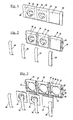
- the front view of the in Fig. 3 shown frame 10 according to the invention after acceptance of the outer inserts can be seen more details.
- the frame has three rectangular recesses for receiving front inserts, each having a central opening 16 in its bottom 18.
- the bottom is provided with four screw holes 20 distributed uniformly over the circumference.
- the depressions are each of two opposite edge strips 22 and two opposite webs 23 limited.
- the triple frame 10 after Fig. 1 to 4 are composed of single frame 24, spacers 26 and end pieces 28.
- Fig. 3 As can be seen from these three elements, as illustrated, complete single frames, double frames, triple frames, and generally any multiple frame can be assembled, and all of these frames can optionally be used for a vertical or horizontal row of switches and / or sockets ,
- the intermediate pieces 26 serve as locking elements of the juxtaposed single frame 24.
- the end pieces 28 are each attached only at the two ends of the juxtaposed single frame 24. Even with a single switch or, a single outlet, the frame is completed by two end pieces 28.
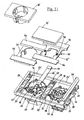
- the 6 and 7 show how the individual frames 24 are designed to work with the in FIGS. 9 and 10 shown intermediate and end pieces 26 and 28 to the in the Fig. 1 to 4 shown unit of a frame 10 according to the invention can be connected.
- these have a width which, taking into account the mutual overlap of the individual frame 24 corresponds to the length and width of an installation sheet, and a height of about 75 mm, so that in the positioning of the frame over three in horizontal row adjacent to each other Installation sheets the center of the overlap area at the right and left marginal edge of a single frame 24 is exactly on the right or left edge of a mounting plate, while the height of the single frame 24 is significantly greater than the height of the installation plates, so that they are completely covered in this extent.
- each individual frame 24 has, in each case outside the two opposite webs 23, a marginal area provided with indentations 30 and projections 32.
- these indentations and protrusions in a front or rear view have substantially the shape of a "Z".
- On each of the two opposite sides of a single frame 24 are each two such Z-shaped projections 32 are present.
- the free ends of the projections 32 on both sides of a single frame 24 in opposite directions, so that when looking at the composite frame 10 according to Fig.
- the Z-shaped projections 32 on the left side of a single frame 24 fit exactly into the Z-shaped indentations in the right edge region of the left-adjacent single frame 24.
- the two engageable edge portions of two adjacent single frame 24 are formed with such indentations 30 and projections 32 that the two cooperating edge regions in the engaged position, apart from the butt joint of the projections in the recesses, form a continuous closed surface.
- the indentations 30 and projections 32 may have any complementary shapes that allow a hooking nesting, so that the composite single frame 24 can not be separated by a tensile force in the longitudinal direction of the frame 10 from each other.
- the Z-shaped indentations 30 and projections 32 are brought into disassembly and disassembled by a relative movement of the individual frames 24 normal to their abutting surface 25 on the wall.
- the interlocked edge regions of the individual frame 24 are locked by the intermediate pieces 26 which fit with its width exactly between the edge strips 22 and after clipping on the front of the frame 10 to the projections 32 from the bottom 18 separating webs 23 and optionally in addition to projections on the projections 32, as in Fig. 6 shown.
- upper and lower hook-shaped ends 34 which are in engagement with their projections 32 edge portions of the individual frame 24 above and below.
- This clenching and clamping of the two composite, provided with projections 32 and therefore relatively wide edge regions ensures good rigidity of the frame 10.
- the intermediate pieces 26 would also prevent a relative displacement of the individual frame 24 transversely to the longitudinal direction of the composite frame 10. It would therefore also be possible to use projections 32 and comparatively larger recesses 30, which are composed transversely to the longitudinal direction of the frame 10 with play, but which can not be adversely affected as a result of the gripping by the intermediate pieces 26.
- edge portions with indentations 30 and projections 32 are also edge portions with indentations 30 and projections 32. These need only from the end pieces 28 on the front and the front side covered to become.
- the end pieces 28 are clipped for this purpose, as well as the intermediate pieces 26 on the edge regions of the individual frame 24 to be covered and are then also with hook-shaped ends 36 on the back of the single frame 24 at.
- the end pieces 28 are formed on an end face with an end wall 40, which covers the projections 32 frontally.
- Fig. 3 and 6 limit the edge strips 22 and webs 23 in the example, a rectangular or square recess, in which the outer inserts 12, 14 integrally formed or mounted rectangular front panels are suitable to use. Because of the rectangular or square outline of the front panels and the depression, there is no need for rotation on the frame for the outer inserts. If the front panels of the outer inserts 14 of the sockets rest on the bottom 18 of the depressions, it is in accordance Fig. 1 the front surface of the outer inserts both flush with the leading edges of the edge strips 22 and with the front surfaces of the intermediate pieces 26 and end pieces 28.
- the front part of the outer insert 12 a switch serves as a rocker and therefore does not need to lie flush with the front surfaces of the intermediate pieces 26, End pieces 28 and the designated front surfaces of the outer inserts 14 of the sockets.
- the edge strips 22 extend beyond the rear surface of the bottom 18 and the projections 32 to the rear. Accordingly, the rear end surfaces 25 of the edge strips 22 form the contact surface, with which the composite frame 10 abuts against the wall.
- the rear end edges of the intermediate pieces 26 and the end pieces 28 lie substantially in the same plane.
- Fig. 11 to 14 are the 22 'margins longer here. They extend to the parting plane between two adjacent individual frames 24, so that only a minimal gap exists between two adjacent edge strips.
- the spacers denoted 26 'do not extend to between the marginal ridges, but are shorter so that they remain within the space bounded by the marginal ridges 22'. Since the intermediate pieces 26 'here also have the function of locking the positive connection of the individual frames 24 to the projections 32, the hook-shaped ends 34 of the intermediate pieces 26' no longer engage around the outer peripheral edges of the individual frames 24, but according to FIG Fig. 11 through holes 27 on the back of the single frame.
- the intermediate pieces 26 ' On the outer side of the single frame are the intermediate pieces 26 ', fitting in width, between the webs 23 on the hooked projections 32 at. So that the hook-shaped ends 34 of the intermediate pieces 26 'do not protrude beyond the rear main plane of the individual frames 24, the connecting regions of the individual frames to be hooked together are formed with ribs 29, the free ends of which collide when joining two individual frames 24, as in FIG Fig. 11 and 12 shown.
- the two adjoining ribs 29 define the opening 27 formed during assembly and are in accordance with Fig. 11 stepped stepped down, so that in each case a hook-shaped end 34 of an intermediate piece 26 'can be hooked to the back of the ribs 29.
- the entanglement of the parts 29, 34 is carried out at both ends of the intermediate pieces 26 'in the same way.
- the ribs 29 at the lateral ends of a frame composed of individual frames 24 serve for clipping in the end pieces 28 covering the outer projections 32.
- the outer inserts are each formed in two parts.
- the rocker switch designated by 12 ' is associated with a lower part 12 "and the lower part 14" is designated by the socket insert 14'.
- On the upper side of the lower part 12 "bearings 44 are integrally formed or mounted, in which a on the underside of the rocker switch 12 'integrally formed pivot axis can be clipped.
- the switch rocker 12 In the case of a horizontal alignment of the frame consisting of two individual frames 24 on a wall, the switch rocker 12 'sits between and above it arranged light diffusion disks 46 which are integrally formed with the lower part 12' of a translucent plastic in the assembled state. Below the along the edge strips 22 'extending light diffusers 46 one or more light emitting diodes 48 are arranged on the lower insert 42, for example, when switching on a non-visible from the switch light source or an electrical device light up, so that the illuminated light diffusers 46 above and below the circuit 12 'indicate the operating state of the corresponding consumer.
- the lower part 14 ' is shaped in the same way as the lower part 12 "with light diffusion disks 46, so that when a plurality of juxtaposed individual frames 24 each above and below the functional units extending over the entire width of the frame extending to the end pieces 28 band of light diffusion disks 46.
- LEDs 48 are installed, which indicate a particular operating state when the consumer is switched on or off via the light diffusion plates 46.
- the embodiments shown illustrate that with a single shape of the single frame 24 in conjunction with a single form of spacers 26 and a single form of end pieces 28 frame for any number of standardized spacing juxtaposed outlets, switches u.
- the low tooling costs allow for a wider range of similarly constructed but differently shaped frames with outer inserts.
- Common to all is the fixed connection of the individual frames 24 directly to each other.
Applications Claiming Priority (1)
| Application Number | Priority Date | Filing Date | Title |
|---|---|---|---|
| DE102007008665A DE102007008665A1 (de) | 2007-02-20 | 2007-02-20 | Rahmen für elektrische Schalter und Steckdosen |
Publications (3)
| Publication Number | Publication Date |
|---|---|
| EP1962388A2 true EP1962388A2 (fr) | 2008-08-27 |
| EP1962388A3 EP1962388A3 (fr) | 2011-09-21 |
| EP1962388B1 EP1962388B1 (fr) | 2013-04-10 |
Family
ID=39449098
Family Applications (1)
| Application Number | Title | Priority Date | Filing Date |
|---|---|---|---|
| EP20080003015 Not-in-force EP1962388B1 (fr) | 2007-02-20 | 2008-02-19 | Cadre pour interrupteurs et prises de courant |
Country Status (2)
| Country | Link |
|---|---|
| EP (1) | EP1962388B1 (fr) |
| DE (1) | DE102007008665A1 (fr) |
Cited By (3)
| Publication number | Priority date | Publication date | Assignee | Title |
|---|---|---|---|---|
| DE102012007763A1 (de) | 2012-04-20 | 2013-10-24 | Ulrich Schmidt | Modularer Rahmen für Steckdosen und Schalter |
| EP3308435A4 (fr) * | 2015-06-12 | 2018-04-18 | Shanutec (Shanghai) Co., Ltd. | Bandelette de sortie d'énergie électrique |
| EP3629435B1 (fr) * | 2018-09-28 | 2022-08-10 | Schneider Electric (Australia) Pty Limited | Ensemble de panneaux et panneau multigang |
Citations (2)
| Publication number | Priority date | Publication date | Assignee | Title |
|---|---|---|---|---|
| DE10251852A1 (de) | 2002-11-07 | 2004-05-19 | Ulrich Schmidt | Rahmen für elektrische Schalter und Steckdosen |
| DE20305756U1 (de) | 2003-04-08 | 2004-09-02 | Polo Industrie Gmbh | Mehrteilige Abdeckung für Elektroinstallationseinsätze |
Family Cites Families (3)
| Publication number | Priority date | Publication date | Assignee | Title |
|---|---|---|---|---|
| DE29513445U1 (de) * | 1994-09-09 | 1995-11-23 | Legrand Oesterreich Gmbh | Abdeckrahmen für Unterputz-Elektroinstallationsgeräte |
| DE4440228B9 (de) * | 1994-11-10 | 2005-08-11 | Kontavill Kontakta Villamosszerelési Részvénytársaság | Elektrische Schalter, Steckdosen u. dgl. für Unterputzmontage |
| EP1039608A1 (fr) * | 1999-03-26 | 2000-09-27 | Interlander Patermann, S.L. | Ensemble modulaire pour mécanismes électriques de surface et/ou à encastrer |
-
2007
- 2007-02-20 DE DE102007008665A patent/DE102007008665A1/de not_active Ceased
-
2008
- 2008-02-19 EP EP20080003015 patent/EP1962388B1/fr not_active Not-in-force
Patent Citations (2)
| Publication number | Priority date | Publication date | Assignee | Title |
|---|---|---|---|---|
| DE10251852A1 (de) | 2002-11-07 | 2004-05-19 | Ulrich Schmidt | Rahmen für elektrische Schalter und Steckdosen |
| DE20305756U1 (de) | 2003-04-08 | 2004-09-02 | Polo Industrie Gmbh | Mehrteilige Abdeckung für Elektroinstallationseinsätze |
Cited By (4)
| Publication number | Priority date | Publication date | Assignee | Title |
|---|---|---|---|---|
| DE102012007763A1 (de) | 2012-04-20 | 2013-10-24 | Ulrich Schmidt | Modularer Rahmen für Steckdosen und Schalter |
| EP3308435A4 (fr) * | 2015-06-12 | 2018-04-18 | Shanutec (Shanghai) Co., Ltd. | Bandelette de sortie d'énergie électrique |
| US10468806B2 (en) | 2015-06-12 | 2019-11-05 | Shanutec (Shanghai) Co., Ltd. | Electrical power outlet strip |
| EP3629435B1 (fr) * | 2018-09-28 | 2022-08-10 | Schneider Electric (Australia) Pty Limited | Ensemble de panneaux et panneau multigang |
Also Published As
| Publication number | Publication date |
|---|---|
| EP1962388A3 (fr) | 2011-09-21 |
| DE102007008665A1 (de) | 2008-08-21 |
| EP1962388B1 (fr) | 2013-04-10 |
Similar Documents
| Publication | Publication Date | Title |
|---|---|---|
| WO1998023005A1 (fr) | Armoire de distribution | |
| DE3042116A1 (de) | Tragbares display system | |
| WO2008028811A1 (fr) | Tiroir | |
| DE102006040358A1 (de) | Einbau-Kältegerät mit Ausgabevorrichtung | |
| EP2681818B1 (fr) | Cadre de montage pour une armoire électrique ou rack | |
| DE4017584A1 (de) | Verbindungsstruktur zum verbinden aneinanderschliessender wandplatten und damit hergestellte versetzbare wand | |
| EP2681817B1 (fr) | Base ou châssis de montage pour une armoire ou un rack | |
| EP0940067A2 (fr) | Armoire de distribution comportant une plaque de montage | |
| WO1998023008A1 (fr) | Profile de chassis pour baie d'armoire de distribution | |
| EP1962388B1 (fr) | Cadre pour interrupteurs et prises de courant | |
| EP1441081B1 (fr) | Connecteur pour profilés et ensemble de connexion | |
| DE2507721A1 (de) | Mosaikschaltwand | |
| EP3333351B1 (fr) | Système de liaison destiné à relier un jambage à un profil de cadre d'une fenêtre ou d'une porte en matière plastique | |
| EP0109569A2 (fr) | Tiroir pour armoire destinée à des systèmes électriques | |
| EP0773615A1 (fr) | Armoire de commutation pour installation électrique | |
| EP2486824A1 (fr) | plinthe pour meuble | |
| WO2003030322A1 (fr) | Socle pour un coffret de distribution | |
| DE102017114389B4 (de) | Anordnung aus einem Schaltschranksockel und einem darauf montierten Schaltschrankrahmengestell sowie eine entsprechende Schaltschrankreihe | |
| EP2831970A1 (fr) | Module de système destiné au génie électrique d'immeubles et au génie des systèmes portiers de communication | |
| DE3243060A1 (de) | Elektrischer schaltschrank | |
| DE3022483C2 (de) | Elektrischer Schalter, insbesondere für Kraftfahrzeuge | |
| DE3312763A1 (de) | Regal | |
| DE202005015033U1 (de) | Blendenrahmen für Sicherungsunterteile für Sammelschienen | |
| EP1125524A1 (fr) | Dispositif de raccordement pour tiroirs de meuble | |
| AT401589B (de) | Unterputz-elektroinstallationsgerät |
Legal Events
| Date | Code | Title | Description |
|---|---|---|---|
| PUAI | Public reference made under article 153(3) epc to a published international application that has entered the european phase |
Free format text: ORIGINAL CODE: 0009012 |
|
| AK | Designated contracting states |
Kind code of ref document: A2 Designated state(s): AT BE BG CH CY CZ DE DK EE ES FI FR GB GR HR HU IE IS IT LI LT LU LV MC MT NL NO PL PT RO SE SI SK TR |
|
| AX | Request for extension of the european patent |
Extension state: AL BA MK RS |
|
| REG | Reference to a national code |
Ref country code: DE Ref legal event code: R079 Ref document number: 502008009662 Country of ref document: DE Free format text: PREVIOUS MAIN CLASS: H01R0013514000 Ipc: H02G0003140000 |
|
| PUAL | Search report despatched |
Free format text: ORIGINAL CODE: 0009013 |
|
| AK | Designated contracting states |
Kind code of ref document: A3 Designated state(s): AT BE BG CH CY CZ DE DK EE ES FI FR GB GR HR HU IE IS IT LI LT LU LV MC MT NL NO PL PT RO SE SI SK TR |
|
| AX | Request for extension of the european patent |
Extension state: AL BA MK RS |
|
| RIC1 | Information provided on ipc code assigned before grant |
Ipc: H01R 25/00 20060101ALI20110812BHEP Ipc: H01R 13/516 20060101ALI20110812BHEP Ipc: H01R 13/514 20060101ALI20110812BHEP Ipc: H02G 3/14 20060101AFI20110812BHEP |
|
| 17P | Request for examination filed |
Effective date: 20120321 |
|
| 17Q | First examination report despatched |
Effective date: 20120427 |
|
| AKX | Designation fees paid |
Designated state(s): AT BE BG CH CY CZ DE DK EE ES FI FR GB GR HR HU IE IS IT LI LT LU LV MC MT NL NO PL PT RO SE SI SK TR |
|
| GRAP | Despatch of communication of intention to grant a patent |
Free format text: ORIGINAL CODE: EPIDOSNIGR1 |
|
| GRAS | Grant fee paid |
Free format text: ORIGINAL CODE: EPIDOSNIGR3 |
|
| GRAA | (expected) grant |
Free format text: ORIGINAL CODE: 0009210 |
|
| AK | Designated contracting states |
Kind code of ref document: B1 Designated state(s): AT BE BG CH CY CZ DE DK EE ES FI FR GB GR HR HU IE IS IT LI LT LU LV MC MT NL NO PL PT RO SE SI SK TR |
|
| REG | Reference to a national code |
Ref country code: GB Ref legal event code: FG4D Free format text: NOT ENGLISH |
|
| REG | Reference to a national code |
Ref country code: AT Ref legal event code: REF Ref document number: 606456 Country of ref document: AT Kind code of ref document: T Effective date: 20130415 Ref country code: CH Ref legal event code: EP |
|
| REG | Reference to a national code |
Ref country code: IE Ref legal event code: FG4D Free format text: LANGUAGE OF EP DOCUMENT: GERMAN |
|
| REG | Reference to a national code |
Ref country code: DE Ref legal event code: R096 Ref document number: 502008009662 Country of ref document: DE Effective date: 20130606 |
|
| REG | Reference to a national code |
Ref country code: NL Ref legal event code: VDEP Effective date: 20130410 Ref country code: LT Ref legal event code: MG4D |
|
| PG25 | Lapsed in a contracting state [announced via postgrant information from national office to epo] |
Ref country code: ES Free format text: LAPSE BECAUSE OF FAILURE TO SUBMIT A TRANSLATION OF THE DESCRIPTION OR TO PAY THE FEE WITHIN THE PRESCRIBED TIME-LIMIT Effective date: 20130721 Ref country code: PT Free format text: LAPSE BECAUSE OF FAILURE TO SUBMIT A TRANSLATION OF THE DESCRIPTION OR TO PAY THE FEE WITHIN THE PRESCRIBED TIME-LIMIT Effective date: 20130812 Ref country code: GR Free format text: LAPSE BECAUSE OF FAILURE TO SUBMIT A TRANSLATION OF THE DESCRIPTION OR TO PAY THE FEE WITHIN THE PRESCRIBED TIME-LIMIT Effective date: 20130711 Ref country code: LT Free format text: LAPSE BECAUSE OF FAILURE TO SUBMIT A TRANSLATION OF THE DESCRIPTION OR TO PAY THE FEE WITHIN THE PRESCRIBED TIME-LIMIT Effective date: 20130410 Ref country code: NL Free format text: LAPSE BECAUSE OF FAILURE TO SUBMIT A TRANSLATION OF THE DESCRIPTION OR TO PAY THE FEE WITHIN THE PRESCRIBED TIME-LIMIT Effective date: 20130410 Ref country code: FI Free format text: LAPSE BECAUSE OF FAILURE TO SUBMIT A TRANSLATION OF THE DESCRIPTION OR TO PAY THE FEE WITHIN THE PRESCRIBED TIME-LIMIT Effective date: 20130410 Ref country code: SE Free format text: LAPSE BECAUSE OF FAILURE TO SUBMIT A TRANSLATION OF THE DESCRIPTION OR TO PAY THE FEE WITHIN THE PRESCRIBED TIME-LIMIT Effective date: 20130410 Ref country code: NO Free format text: LAPSE BECAUSE OF FAILURE TO SUBMIT A TRANSLATION OF THE DESCRIPTION OR TO PAY THE FEE WITHIN THE PRESCRIBED TIME-LIMIT Effective date: 20130710 Ref country code: IS Free format text: LAPSE BECAUSE OF FAILURE TO SUBMIT A TRANSLATION OF THE DESCRIPTION OR TO PAY THE FEE WITHIN THE PRESCRIBED TIME-LIMIT Effective date: 20130810 |
|
| PG25 | Lapsed in a contracting state [announced via postgrant information from national office to epo] |
Ref country code: LV Free format text: LAPSE BECAUSE OF FAILURE TO SUBMIT A TRANSLATION OF THE DESCRIPTION OR TO PAY THE FEE WITHIN THE PRESCRIBED TIME-LIMIT Effective date: 20130410 Ref country code: PL Free format text: LAPSE BECAUSE OF FAILURE TO SUBMIT A TRANSLATION OF THE DESCRIPTION OR TO PAY THE FEE WITHIN THE PRESCRIBED TIME-LIMIT Effective date: 20130410 Ref country code: HR Free format text: LAPSE BECAUSE OF FAILURE TO SUBMIT A TRANSLATION OF THE DESCRIPTION OR TO PAY THE FEE WITHIN THE PRESCRIBED TIME-LIMIT Effective date: 20130410 Ref country code: CY Free format text: LAPSE BECAUSE OF FAILURE TO SUBMIT A TRANSLATION OF THE DESCRIPTION OR TO PAY THE FEE WITHIN THE PRESCRIBED TIME-LIMIT Effective date: 20130410 Ref country code: BG Free format text: LAPSE BECAUSE OF FAILURE TO SUBMIT A TRANSLATION OF THE DESCRIPTION OR TO PAY THE FEE WITHIN THE PRESCRIBED TIME-LIMIT Effective date: 20130710 |
|
| PG25 | Lapsed in a contracting state [announced via postgrant information from national office to epo] |
Ref country code: SK Free format text: LAPSE BECAUSE OF FAILURE TO SUBMIT A TRANSLATION OF THE DESCRIPTION OR TO PAY THE FEE WITHIN THE PRESCRIBED TIME-LIMIT Effective date: 20130410 Ref country code: DK Free format text: LAPSE BECAUSE OF FAILURE TO SUBMIT A TRANSLATION OF THE DESCRIPTION OR TO PAY THE FEE WITHIN THE PRESCRIBED TIME-LIMIT Effective date: 20130410 Ref country code: CZ Free format text: LAPSE BECAUSE OF FAILURE TO SUBMIT A TRANSLATION OF THE DESCRIPTION OR TO PAY THE FEE WITHIN THE PRESCRIBED TIME-LIMIT Effective date: 20130410 Ref country code: EE Free format text: LAPSE BECAUSE OF FAILURE TO SUBMIT A TRANSLATION OF THE DESCRIPTION OR TO PAY THE FEE WITHIN THE PRESCRIBED TIME-LIMIT Effective date: 20130410 |
|
| PLBE | No opposition filed within time limit |
Free format text: ORIGINAL CODE: 0009261 |
|
| STAA | Information on the status of an ep patent application or granted ep patent |
Free format text: STATUS: NO OPPOSITION FILED WITHIN TIME LIMIT |
|
| PG25 | Lapsed in a contracting state [announced via postgrant information from national office to epo] |
Ref country code: RO Free format text: LAPSE BECAUSE OF FAILURE TO SUBMIT A TRANSLATION OF THE DESCRIPTION OR TO PAY THE FEE WITHIN THE PRESCRIBED TIME-LIMIT Effective date: 20130410 Ref country code: IT Free format text: LAPSE BECAUSE OF FAILURE TO SUBMIT A TRANSLATION OF THE DESCRIPTION OR TO PAY THE FEE WITHIN THE PRESCRIBED TIME-LIMIT Effective date: 20130410 |
|
| 26N | No opposition filed |
Effective date: 20140113 |
|
| REG | Reference to a national code |
Ref country code: DE Ref legal event code: R097 Ref document number: 502008009662 Country of ref document: DE Effective date: 20140113 |
|
| BERE | Be: lapsed |
Owner name: SCHMIDT, ULRICH Effective date: 20140228 |
|
| PG25 | Lapsed in a contracting state [announced via postgrant information from national office to epo] |
Ref country code: LU Free format text: LAPSE BECAUSE OF FAILURE TO SUBMIT A TRANSLATION OF THE DESCRIPTION OR TO PAY THE FEE WITHIN THE PRESCRIBED TIME-LIMIT Effective date: 20140219 Ref country code: MC Free format text: LAPSE BECAUSE OF FAILURE TO SUBMIT A TRANSLATION OF THE DESCRIPTION OR TO PAY THE FEE WITHIN THE PRESCRIBED TIME-LIMIT Effective date: 20130410 |
|
| REG | Reference to a national code |
Ref country code: CH Ref legal event code: PL |
|
| GBPC | Gb: european patent ceased through non-payment of renewal fee |
Effective date: 20140219 |
|
| PG25 | Lapsed in a contracting state [announced via postgrant information from national office to epo] |
Ref country code: LI Free format text: LAPSE BECAUSE OF NON-PAYMENT OF DUE FEES Effective date: 20140228 Ref country code: CH Free format text: LAPSE BECAUSE OF NON-PAYMENT OF DUE FEES Effective date: 20140228 |
|
| REG | Reference to a national code |
Ref country code: FR Ref legal event code: ST Effective date: 20141031 |
|
| REG | Reference to a national code |
Ref country code: IE Ref legal event code: MM4A |
|
| PG25 | Lapsed in a contracting state [announced via postgrant information from national office to epo] |
Ref country code: FR Free format text: LAPSE BECAUSE OF NON-PAYMENT OF DUE FEES Effective date: 20140228 Ref country code: IE Free format text: LAPSE BECAUSE OF NON-PAYMENT OF DUE FEES Effective date: 20140219 Ref country code: GB Free format text: LAPSE BECAUSE OF NON-PAYMENT OF DUE FEES Effective date: 20140219 Ref country code: BE Free format text: LAPSE BECAUSE OF NON-PAYMENT OF DUE FEES Effective date: 20140228 |
|
| PG25 | Lapsed in a contracting state [announced via postgrant information from national office to epo] |
Ref country code: SI Free format text: LAPSE BECAUSE OF FAILURE TO SUBMIT A TRANSLATION OF THE DESCRIPTION OR TO PAY THE FEE WITHIN THE PRESCRIBED TIME-LIMIT Effective date: 20130410 |
|
| REG | Reference to a national code |
Ref country code: DE Ref legal event code: R082 Ref document number: 502008009662 Country of ref document: DE Representative=s name: PATENTANWAELTE OLBRICHT, BUCHHOLD, KEULERTZ PA, DE |
|
| PG25 | Lapsed in a contracting state [announced via postgrant information from national office to epo] |
Ref country code: MT Free format text: LAPSE BECAUSE OF FAILURE TO SUBMIT A TRANSLATION OF THE DESCRIPTION OR TO PAY THE FEE WITHIN THE PRESCRIBED TIME-LIMIT Effective date: 20130410 |
|
| PGFP | Annual fee paid to national office [announced via postgrant information from national office to epo] |
Ref country code: AT Payment date: 20160226 Year of fee payment: 9 |
|
| PG25 | Lapsed in a contracting state [announced via postgrant information from national office to epo] |
Ref country code: TR Free format text: LAPSE BECAUSE OF FAILURE TO SUBMIT A TRANSLATION OF THE DESCRIPTION OR TO PAY THE FEE WITHIN THE PRESCRIBED TIME-LIMIT Effective date: 20130410 Ref country code: HU Free format text: LAPSE BECAUSE OF FAILURE TO SUBMIT A TRANSLATION OF THE DESCRIPTION OR TO PAY THE FEE WITHIN THE PRESCRIBED TIME-LIMIT; INVALID AB INITIO Effective date: 20080219 |
|
| PGFP | Annual fee paid to national office [announced via postgrant information from national office to epo] |
Ref country code: DE Payment date: 20160414 Year of fee payment: 9 |
|
| REG | Reference to a national code |
Ref country code: DE Ref legal event code: R119 Ref document number: 502008009662 Country of ref document: DE |
|
| REG | Reference to a national code |
Ref country code: AT Ref legal event code: MM01 Ref document number: 606456 Country of ref document: AT Kind code of ref document: T Effective date: 20170219 |
|
| PG25 | Lapsed in a contracting state [announced via postgrant information from national office to epo] |
Ref country code: AT Free format text: LAPSE BECAUSE OF NON-PAYMENT OF DUE FEES Effective date: 20170219 |
|
| PG25 | Lapsed in a contracting state [announced via postgrant information from national office to epo] |
Ref country code: DE Free format text: LAPSE BECAUSE OF NON-PAYMENT OF DUE FEES Effective date: 20170901 |