EP1962011A1 - Device with controllable protection device - Google Patents
Device with controllable protection device Download PDFInfo
- Publication number
- EP1962011A1 EP1962011A1 EP08002417A EP08002417A EP1962011A1 EP 1962011 A1 EP1962011 A1 EP 1962011A1 EP 08002417 A EP08002417 A EP 08002417A EP 08002417 A EP08002417 A EP 08002417A EP 1962011 A1 EP1962011 A1 EP 1962011A1
- Authority
- EP
- European Patent Office
- Prior art keywords
- control
- storage capacitor
- controller
- control element
- switching element
- Prior art date
- Legal status (The legal status is an assumption and is not a legal conclusion. Google has not performed a legal analysis and makes no representation as to the accuracy of the status listed.)
- Granted
Links
Images


Classifications
-
- D—TEXTILES; PAPER
- D06—TREATMENT OF TEXTILES OR THE LIKE; LAUNDERING; FLEXIBLE MATERIALS NOT OTHERWISE PROVIDED FOR
- D06F—LAUNDERING, DRYING, IRONING, PRESSING OR FOLDING TEXTILE ARTICLES
- D06F34/00—Details of control systems for washing machines, washer-dryers or laundry dryers
- D06F34/10—Power supply arrangements, e.g. stand-by circuits
-
- D—TEXTILES; PAPER
- D06—TREATMENT OF TEXTILES OR THE LIKE; LAUNDERING; FLEXIBLE MATERIALS NOT OTHERWISE PROVIDED FOR
- D06F—LAUNDERING, DRYING, IRONING, PRESSING OR FOLDING TEXTILE ARTICLES
- D06F39/00—Details of washing machines not specific to a single type of machines covered by groups D06F9/00 - D06F27/00
- D06F39/12—Casings; Tubs
- D06F39/14—Doors or covers; Securing means therefor
-
- D—TEXTILES; PAPER
- D06—TREATMENT OF TEXTILES OR THE LIKE; LAUNDERING; FLEXIBLE MATERIALS NOT OTHERWISE PROVIDED FOR
- D06F—LAUNDERING, DRYING, IRONING, PRESSING OR FOLDING TEXTILE ARTICLES
- D06F37/00—Details specific to washing machines covered by groups D06F21/00 - D06F25/00
- D06F37/42—Safety arrangements, e.g. for stopping rotation of the receptacle upon opening of the casing door
-
- D—TEXTILES; PAPER
- D06—TREATMENT OF TEXTILES OR THE LIKE; LAUNDERING; FLEXIBLE MATERIALS NOT OTHERWISE PROVIDED FOR
- D06F—LAUNDERING, DRYING, IRONING, PRESSING OR FOLDING TEXTILE ARTICLES
- D06F2103/00—Parameters monitored or detected for the control of domestic laundry washing machines, washer-dryers or laundry dryers
- D06F2103/40—Opening or locking status of doors
Landscapes
- Engineering & Computer Science (AREA)
- Textile Engineering (AREA)
- Control Of Washing Machine And Dryer (AREA)
Abstract
Description
Die vorliegende Erfindung betrifft ein Gerät mit einer ansteuerbaren Schutzeinrichtung nach dem Oberbegriff des Anspruchs 1.The present invention relates to a device with a controllable protective device according to the preamble of claim 1.
Geräte mit einer gefährdenden Einrichtung sind zur Vermeidung von unsachgemäßem Gebrauch mit einer Schutzeinrichtung versehen, die bevorzugt elektrisch ansteuerbar ist. Bei einem Gerät mit einer gefährdenden Einrichtung kann es sich beispielsweise um ein Wäschebehandlungsgerät handeln. Beim Betrieb von Wäschebehandlungsgeräten, insbesondere von Waschmaschinen, muss sichergestellt werden, dass die Tür zum Bestücken des Geräts nur dann geöffnet werden kann, wenn dies ohne Schaden für den Benutzer möglich ist. Eine Türöffnung muss beispielsweise verhindert werden, wenn sich (heißes) Wasser in der Trommel befindet oder wenn sich die Trommel mit mehr als etwa 60 U/min dreht.Devices with a hazardous device are provided to prevent improper use with a protective device, which is preferably electrically controlled. For example, a device with a hazardous device may be a laundry treatment device. When operating laundry treatment appliances, especially washing machines, it must be ensured that the door can only be opened to load the appliance if this is possible without harm to the user. For example, a door opening must be prevented when (hot) water is in the drum or when the drum is rotating at more than about 60 rpm.
Ein klassisches Element, das zur Verriegelung der Maschinentür eingesetzt wird, ist zum Beispiel aus einem Bimetall gebildet, das über eine PTC-Pille aufgeheizt wird, einen Verriegelungsnocken treibt und gleichzeitig, wenn die Verriegelung erfolgreich ist, einen Kontakt schließt. Über diesen Kontakt, d.h. erst mit der sicheren Verriegelung der Tür, wird den Leistungselementen der Maschine Energie zugeführt. Ein solches Türverriegelungselement ist zum Beispiel in der
Weiter ist zum Beispiel aus der
Bei einer weiteren Art von Türverriegelung verriegelt sich die Tür beim Schließen entweder selbständig mechanisch oder wird durch einen Ansteuerimpuls aktiv verriegelt. Die Verriegelung kann mit einem Magneten des Türverriegelungselements ohne Eigenverzögerung durch Ansteuerung mit kurzen Impulsen deaktiviert oder aktiv geöffnet werden, um die Beladungstür der Waschmaschine zu entriegeln. Solche Türverriegelungen werden meistens alleine über Schalter von der Elektronik gesteuert, weil dies eine größere Freiheit in der Programmgestaltung der Wäschebehandlung ergibt. Bei einem Kurzschluss des Ansteuerschalters wäre die Tür jedoch dauernd entriegelt. Um Sicherheit gegen unerlaubtes Öffnen der Tür zu erhalten, ist es z.B. Stand der Technik, zwei in Serie liegende unabhängige Ansteuerkreise zu nutzen. Dies ist jedoch aufwändig in Bezug auf den Platzverbrauch der Ansteuerschaltung und nicht kostengünstig.In another type of door lock, the door locks when closing either mechanically or is actively locked by a drive pulse. The lock can be deactivated with a magnet of the door locking element without self-delay by driving with short pulses or actively opened to unlock the loading door of the washing machine. Such door locks are mostly controlled solely by switches from the electronics, because this results in a greater freedom in the program design of the laundry treatment. In the event of a short circuit of the control switch, however, the door would be permanently unlocked. In order to protect against unauthorized opening of the door, it is e.g. State of the art to use two independent drive circuits in series. However, this is expensive in terms of the space consumption of the drive circuit and not cost.
Abhilfe kann zum Beispiel dadurch erreicht werden, bei nur einfacher Ansteuerung die Türverriegelung so zu gestalten, dass mindestens zwei Impulse zur Entriegelung notwendig sind. Ein derartiges Türverriegelungselement, das mit einem Zahnrad und einer Klinke arbeitet, ist in der
Eine Lösung des letztgenannten Problems besteht darin, das Tachosignal, welches der rotierende Motor abgibt, mit der Ansteuerschaltung des Türverriegelungselements zu verknüpfen. Dies geschieht derart, dass die Steuerimpulse zum Öffnen der Verriegelung bei rotierender Trommel hardwaremäßig verhindert werden.A solution to the latter problem is to combine the tacho signal, which emits the rotating motor, with the drive circuit of the door locking element. This is done in such a way that the control pulses for opening the lock with rotating drum are prevented by hardware.
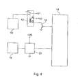
Es ist außerdem eine Ansteuerschaltung für ein Wäschebehandlungsgerät bekannt, die wie in
Diese herkömmliche Ansteuerschaltung eines Wäschebehandlungsgeräts steuert eine Motorsteuerung 10 einer Waschmaschinentrommel als ein Beispiel einer elektrisch ansteuerbaren, gefährdenden Einrichtung. Die Versorgungsspannung V1 der Motorsteuerung 10 kann mittels eines Relais 12 als einem ersten Steuerelement durch einen Mikrocontroller 14 zu- und abgeschaltet werden. Bei Abschaltung der Versorgungsspannung V1 ist der gefährdende Zustand sofort oder nach einer gewissen Zeit nicht mehr vorhanden. Das Relais 12 wird üblicherweise über einen Transistor oder dergleichen Schaltelement 16 angesteuert.This conventional driving circuit of a laundry treating machine controls an
Um den Benutzer der Waschmaschine vor einer Gefährdung zum Beispiel durch eine rotierende Wäschetrommel zu schützen, ist ein Türverriegelungselement (z.B. der magnetische Verschluss der Waschmaschinentür) 18 als eine elektrisch steuerbare und elektrisch deaktivierbare Schutzeinrichtung vorgesehen. Zur Ansteuerung des Türverriegelungselements 18 durch den Mikrocontroller 14 dient ein zweites Steuerelement 20, das zum Beispiel als Triac ausgebildet ist, der über einen Transistor Triggerimpulse erhält.In order to protect the user of the washing machine from being endangered by, for example, a rotary laundry drum, a door locking element (e.g., the magnetic closure of the washing machine door) 18 is provided as an electrically controllable and electrically deactivatable guard. For controlling the
Beide Steuerelemente 12, 20 der Motorsteuerung 10 und des Türverriegelungselements 18 besitzen eine unabhängige Versorgungsspannung. Aus diesem Grund kann der Benutzer der Waschmaschine einer Gefährdung ausgesetzt sein, wenn durch einen Fehler im zweiten Steuerelement 20, einen Softwarefehler des Mikrocontrollers 14, eine elektromagnetische Störung oder durch ein anderes Ereignis das Türverriegelungselement 18 außer Kraft gesetzt ist.Both controls 12, 20 of the
Der vorliegenden Erfindung liegt die Aufgabe zugrunde, ein Gerät mit einer gefährdenden Einrichtung derart weiterzuentwickeln, dass die Funktionssicherheit der Schutzeinrichtung weiter erhöht ist.The present invention has for its object to further develop a device with a hazardous device such that the reliability of the protective device is further increased.
Diese Aufgabe wird gelöst durch ein Gerät mit den Merkmalen des Anspruchs 1. Vorteilhafte Ausgestaltungen und Weiterbildungen der Erfindung sind Gegenstand der abhängigen Ansprüche.This object is achieved by a device having the features of claim 1. Advantageous embodiments and further developments of the invention are the subject of the dependent claims.
Das Gerät mit einer gefährdenden Einrichtung enthält eine erste Steuerung, die über ein erstes Steuerelement angesteuert wird, welches wiederum über ein erstes Schaltelement von einer Steuerung angesteuert wird, und eine elektrisch ansteuerbare Schutzeinrichtung, die über ein zweites Steuerelement angesteuert wird, wobei die elektrisch ansteuerbare Schutzeinrichtung deaktivierbar ist. Weiter ist zwischen dem ersten und dem zweiten Steuerelement ein Speicherkondensator vorgesehen, der das zweite Steuerelement mit Energie für einen Steuerimpuls versorgt und der bei abgeschalteter erster Steuerung über das erste Steuerelement geladen und bei eingeschalteter erster Steuerung über das erste Schaltelement entladen wird.The device with a hazardous device includes a first control, which is controlled by a first control, which in turn is controlled by a controller via a first switching element, and an electrically controllable protective device, which is controlled via a second control element, wherein the electrically controllable protective device can be deactivated. Next is between the a first and the second control a storage capacitor provided, which supplies the second control element with energy for a control pulse and is loaded when the first control is switched off via the first control element and discharged when the first control via the first switching element.
Im Gegensatz zu der in
In einer Ausgestaltung der Erfindung ist zwischen den Speicherkondensator und das erste Schaltelement ein Ladewiderstand geschaltet, sodass der Speicherkondensator mit einer bestimmten Zeitverzögerung aufgeladen wird. Diese Zeitverzögerung durch den Ladewiderstand ist vorzugsweise so bemessen, dass der Gefährdungszustand durch die erste Steuerung sicher beendet ist.In one embodiment of the invention, a charging resistor is connected between the storage capacitor and the first switching element, so that the storage capacitor is charged with a certain time delay. This time delay through the charging resistor is preferably dimensioned such that the hazardous condition is safely ended by the first controller.
In einer weiteren Ausgestaltung der Erfindung ist zwischen den Speicherkondensator und das erste Steuerelement eine Reihenschaltung aus einem Entladewiderstand und einer Diode geschaltet, sodass der Speicherkondensator bei eingeschalteter erster Steuerung schnell über den Entladewiderstand entladen werden kann.In a further embodiment of the invention, a series connection of a discharge resistor and a diode is connected between the storage capacitor and the first control element, so that the storage capacitor can be discharged quickly via the discharge resistor when the first control is switched on.
In einem Ausführungsbeispiel ist das zweite Steuerelement ein Triac, der über ein zweites Schaltelement von der Steuerung mit der Energie des Speicherkondensators getriggert wird. In einem alternativen Ausführungsbeispiel ist das zweite Steuerelement ein Relais, das über ein zweites Schaltelement von der Steuerung mit der Energie des Speicherkondensators erregt wird.In one embodiment, the second control element is a triac which is triggered by the controller with the energy of the storage capacitor via a second switching element. In an alternative embodiment, the second control element is a relay which is energized by the controller with the energy of the storage capacitor via a second switching element.
In einer noch weiteren Ausgestaltung der Erfindung sind das erste Steuerelement und das erste Schaltelement in einem separaten Modul integriert.In a still further embodiment of the invention, the first control element and the first switching element are integrated in a separate module.
In einer bevorzugten Alternative ist das Gerät ein Wäschebehandlungsgerät, insbesondere eine Waschmaschine. Zweckmäßiger Weise ist die gefährdende Einrichtung eine antreibbare Wäschetrommel. Vorteilhafter Weise ist die erste Steuerung eine Motorsteuerung. In einer besonders vorteilhaften Weise ist die elektrisch ansteuerbare Schutzeinrichtung ein Türverriegelungselement.In a preferred alternative, the device is a laundry treatment device, in particular a washing machine. Conveniently, the hazardous device is a drivable laundry drum. Advantageously, the first controller is a motor controller. In a particularly advantageous manner, the electrically controllable protective device is a door locking element.
In einer bevorzugten Alternative ist die elektrisch ansteuerbare Schutzeinrichtung über mindestens zwei Steuerimpulse deaktivierbar. Hierdurch wird gewährleistet, dass die elektrisch ansteuerbare Schutzeinrichtung nicht mehr deaktiviert werden kann, weil zur Deaktivierung mindestens zwei Steuerimpulse erforderlich sind, der Speicherkondensator aber nur Energie für einen solchen Steuerimpuls zur Verfügung stellen kann, wenn er nicht wieder aufgeladen wird.In a preferred alternative, the electrically controllable protective device can be deactivated via at least two control pulses. This ensures that the electrically controllable protective device can not be deactivated because at least two control pulses are required for deactivation, but the storage capacitor can only provide energy for such a control pulse if it is not recharged.
Obige sowie weitere Merkmale und Vorteile der Erfindung werden aus der nachfolgenden Beschreibung bevorzugter, nicht-einschränkender Ausführungsbeispiele unter Bezugnahme auf die beiliegenden Zeichnungen besser verständlich. Darin zeigen:
- Fig. 1
- eine schematische Darstellung einer Ansteuerschaltung gemäß einem ersten Ausführungsbeispiel eines Wäschebehandlungsgeräts der vorliegenden Erfindung;
- Fig. 2
- eine schematische Darstellung einer Ansteuerschaltung gemäß einem zweiten Ausführungsbeispiel eines Wäschebehandlungsgeräts der vorliegenden Erfindung;
- Fig. 3
- eine detailliertere Darstellung der Ansteuerschaltung von
Fig. 2 ; und - Fig. 4
- eine schematische Darstellung einer herkömmlichen Ansteuerschaltung eines Wäschebehandlungsgeräts.
- Fig. 1
- a schematic representation of a drive circuit according to a first embodiment of a laundry treatment device of the present invention;
- Fig. 2
- a schematic representation of a drive circuit according to a second embodiment of a laundry treatment device of the present invention;
- Fig. 3
- a more detailed representation of the drive circuit of
Fig. 2 ; and - Fig. 4
- a schematic representation of a conventional drive circuit of a laundry treatment appliance.
Anhand von
Die Versorgungsspannung V1 für die Motorsteuerung (z.B. Frequenzumrichter) 10 der Waschmaschine wird über ein erstes Steuerelement 12 in Form eines Relais zugeführt bzw. unterbrochen. Die Ansteuerung des ersten Steuerelements 12 erfolgt ihrerseits von einer Steuerung (z.B. Mikrocontroller) 14 über ein erstes Schaltelement 16 in Form eines Transistors, Treibers oder dergleichen Schaltelement. Wird die Versorgung der Motorsteuerung 10 mit der Versorgungsspannung V1 durch das erste Steuerelement 12 unterbrochen, so ist ein gefährdender Zustand für den Benutzer durch die Motorsteuerung 10 nach einer gewissen Zeit T nicht mehr vorhanden, beispielsweise ist die Drehzahl der Wäschetrommel unter einen vorbestimmten Grenzwert abgesunken.The power supply voltage V1 for the motor control (e.g., frequency converter) 10 of the washing machine is supplied through a
Zum Schutz des Benutzers der Waschmaschine ist ferner ein Türverriegelungselement 18 vorgesehen, das die Tür zur Beladung der Wäschetrommel vorzugsweise automatisch verriegelt und nur bei sicher verriegelter Tür eine Ansteuerung der Motorsteuerung 10 erlaubt. Dieses Türverriegelungselement 18 wird von der Steuerung 14 über ein zweites Steuerelement 20 angesteuert, d.h. bei Bedarf deaktiviert, um die Tür zu entriegeln und damit ein Öffnen der Tür zu ermöglichen. Hierbei sind zur Deaktivierung des Türverriegelungselements 18 mindestens zwei Steuerimpulse des zweiten Steuerelements 20 erforderlich.To protect the user of the washing machine, a
Die Energieversorgung dieses zweiten Steuerelements 20 zum Erzeugen der Steuerimpulse zur Deaktivierung des Türverriegelungselements 18 erfolgt über einen Speicherkondensator 22, der zwischen dem ersten und dem zweiten Steuerelement 12, 20 vorgesehen ist. Der Speicherkondensator 22 ist dabei über einen Ladewiderstand 24 mit dem ersten Steuerelement 12 verbunden.The power supply of this
Wenn die Motorsteuerung 10 abgeschaltet ist, d.h. das erste Steuerelement 12 die Versorgungsspannung V1 zur Motorsteuerung 10 unterbricht, wird der Speicherkondensator 22 über den Ladewiderstand 24 mit der Versorgungsspannung V0 des ersten Steuerelements 12 aufgeladen. Die zum Aufladen des Speicherkondensators 22 benötigte Zeit T1 ist dabei vorzugsweise länger als die obige Zeit T bis zum Erreichen des sicheren Zustandes nach dem Abschalten der Motorsteuerung 10.When the
Der so aufgeladene Speicherkondensator 22 stellt die zum Erzeugen der Steuerimpulse durch das zweite Steuerelement 20, d.h. zum Deaktivieren des Türverriegelungselements 18 erforderliche Energie zur Verfügung. Die Energie des aufgeladenen Speicherkondensators 22 reicht dabei zum Erzeugen eines Steuerimpulses.The thus charged
Das zweite Steuerelement 20 ist beispielsweise ein Triac, der über ein zweites Schaltelement (z.B. Transistor) 30 (siehe
Wird die Motorsteuerung 10 durch das erste Steuerelement 12 mit Energie versorgt, wird das erste Schaltelement 16 durchgesteuert. In diesem Zustand entlädt sich der Speicherkondensator 22 über den Ladewiderstand 24 in einer bestimmten Zeit. Nach Ablauf einer kurzen Zeitdauer kann das Türverriegelungselement 18 bereits nicht mehr deaktiviert werden, weil der Speicherkondensator 22 nicht genügend Energie zum Erzeugen eines Steuerimpulses durch das zweite Steuerelement 20 bereitstellt.If the
Ferner führt jede Unterbrechung einer Verbindungsleitung oder eines Bauteils dazu, dass entweder die Motorsteuerung 10 nicht mehr mit Energie versorgt werden kann oder dass das Türverriegelungselement 18 nicht mehr deaktiviert werden kann, weil hierfür keine Energie zur Verfügung steht. Gleiches gilt auch für den Fall eines Kurzschlusses des Transistors 16 oder des zweiten Steuerelements 20, weil der Speicherkondensator 22 nur die Energie für einen Steuerimpuls des zweiten Schaltelements 20 liefert, für eine Deaktivierung des Türverriegelungselements 18 aber zwei solcher Steuerimpulse erforderlich sind. Auch eine fehlerhafte Ansteuerung des Türverriegelungselements 18 durch die Steuerung oder EMV-Störungen, die eine fälschliche Deaktivierung des Türverriegelungselements 18 bewirken, können vermieden werden. Dies ist auch dann möglich, wenn keine Tachoimpulse des Motors zur Auswertung zur Verfügung stehen.Furthermore, any interruption of a connection line or a component causes either the
Die in
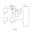
Ein zweites Ausführungsbeispiel einer Ansteuerschaltung einer Waschmaschine wird nun Bezug nehmend auf
Das zweite Ausführungsbeispiel unterscheidet sich von der obigen ersten Ansteuerschaltung dadurch, dass parallel zu dem Ladewiderstand 24 eine Reihenschaltung aus einem Entladewiderstand 26 und einer Diode 28 geschaltet ist. Dieser Schaltungsaufbau ermöglicht unterschiedliche Zeiten für den Ladevorgang und den Entladevorgang des Speicherkondensators.The second embodiment differs from the above first drive circuit in that a series circuit of a
Beim Zuschalten der Versorgungsspannung V1 auf die Motorsteuerung 10 durch das erste Schaltelement 12 wird der Speicherkondensator 22 in diesem Fall über den Entladewiderstand 26 und die Diode 28 mit einer Zeitkonstante T2 entladen, die kürzer als die Zeitkonstante T1 für den Ladevorgang des Speicherkondensators 22 über den Ladewiderstand 24 ist. Auf diese Weise ist eine Deaktivierung des Türverriegelungselements 18 bereits sehr kurze Zeit nach dem Einschalten der Motorsteuerung 10 nicht mehr möglich. Nach dem Abschalten der Motorsteuerung 10 kann die Tür der Wäschetrommel erst nach einer Zeit T1 (> T) deaktiviert werden.When connecting the supply voltage V1 to the
Die weiteren Merkmale und Vorteile dieser zweiten Ansteuerschaltung sind gleich jenen des oben beschriebenen ersten Ausführungsbeispiels.The other features and advantages of this second drive circuit are the same as those of the first embodiment described above.
Eine detailliertere Darstellung einer Ansteuerschaltung des oben beschriebenen zweiten Ausführungsbeispiels ist in
Das Türverriegelungselement 18 verriegelt sich beim Schließen der Tür 19 der Wäschetrommel automatisch und betätigt mit einem Verriegelungsnocken einen Schalter 18a. Der Netzanschluss L wird dann über diesen Schalter 18a als L' an die Leistungselemente der Waschmaschine gelegt. Die Motorsteuerung 10 wird von der Steuerung 14 über den Schalter 12a des Relais 12 eingeschaltet. In diesem Zustand, d.h. wenn der Motor und damit die Wäschetrommel dreht, liegt am Kollektor des Transistors 16 eine Spannung von 0 V und der Speicherkondensator 22 wird über den Entladewiderstand 26 und die Diode 28 entladen.The
Das Türverriegelungselement 18 weist ferner einen Magneten 18b zum magnetischen Auslösen des Schalters 18a auf. Der Triac 20, der diesen Magneten 18b betätigt, kann mit einem Signal von der Steuerung über den Transistor (zweites Schaltelement der Erfindung) 30 mit der Energie aus dem Speicherkondensator 22 getriggert werden.The
Sobald die Steuerung 14 den Transistor 16 sperrt, fällt das Relais 12 ab und sein Schalter 12a öffnet den Anschluss zur Motorsteuerung 10. Am Kollektor des Transistors 16 liegt dann vom Netzteil 32 die Spannung U, geführt über die Relaiswicklung des Relais 12. Der Speicherkondensator 22 lädt sich jetzt über den Ladewiderstand 24 mit der entsprechenden Zeitkonstante T1 auf. Nun, d.h. im stromlosen Zustand der Motorsteuerung 10, kann die Tür 1 durch die Steuerung 14 über Transistor 30, Triac 20 und Türverriegelungselement 18 entriegelt werden, wobei der Transistor 30 die zum Triggern des Triacs 20 notwendige Energie dem Speicherkondensator 22 entnimmt.As soon as the
Sobald die Motorsteuerung 10 von der Steuerung 14 wieder über den Transistor 16 und das Relais 12 mit dem Schalter 12a an die Versorgungsspannung gelegt wird, entlädt der Transistor 16 den Speicherkondensator 22 schnell über den Entladewiderstand 26 und die Diode 28. Eine Entriegelung der Tür 19 ist dann nicht mehr möglich.Once the
Claims (11)
einer ersten Steuerung (10), die über ein erstes Steuerelement (12) angesteuert wird, welches wiederum über ein erstes Schaltelement (16) von einer zweiten Steuerung (14) angesteuert wird; und
einer elektrisch ansteuerbaren Schutzeinrichtung (18), die über ein zweites Steuerelement (20) angesteuert wird, wobei die elektrisch ansteuerbare Schutzeinrichtung (18) deaktivierbar ist,
dadurch gekennzeichnet,
dass zwischen dem ersten und dem zweiten Steuerelement (12, 20) ein Speicherkondensator (22) vorgesehen ist, der das zweite Steuerelement (20) mit Energie für einen Steuerimpuls versorgt und der bei abgeschalteter erster Steuerung (10) über das erste Steuerelement (12) geladen und bei eingeschalteter erster Steuerung (10) über das erste Schaltelement (16) entladen wird.Device with a hazardous device, with
a first controller (10), which is controlled via a first control element (12), which in turn is controlled by a second control (14) via a first switching element (16); and
an electrically controllable protective device (18), which is controlled via a second control element (20), wherein the electrically activatable protective device (18) can be deactivated,
characterized,
in that a storage capacitor (22) is provided between the first and the second control element (12, 20), which supplies the second control element (20) with energy for a control pulse and which, when the first control (10) is switched off, is transmitted via the first control element (12). is charged and discharged when the first controller (10) via the first switching element (16).
dadurch gekennzeichnet,
dass zwischen den Speicherkondensator (22) und das erste Schaltelement (16) ein Ladewiderstand (24) geschaltet ist.Apparatus according to claim 1,
characterized,
in that a charging resistor (24) is connected between the storage capacitor (22) and the first switching element (16).
dadurch gekennzeichnet,
dass zwischen den Speicherkondensator (22) und das erste Steuerelement (12) eine Reihenschaltung aus einem Entladewiderstand (26) und einer Diode (28) geschaltet ist.Apparatus according to claim 1 or 2,
characterized,
in that a series connection of a discharge resistor (26) and a diode (28) is connected between the storage capacitor (22) and the first control element (12).
dadurch gekennzeichnet,
dass das zweite Steuerelement (20) ein Triac ist, der über ein zweites Schaltelement (30) von der zweiten Steuerung (14) mit der Energie des Speicherkondensators (22) getriggert wird.Device according to one of claims 1 to 3,
characterized,
in that the second control element (20) is a triac which is triggered by the second control (14) with the energy of the storage capacitor (22) via a second switching element (30).
dadurch gekennzeichnet,
dass das zweite Steuerelement (20) ein Relais ist, das über ein zweites Schaltelement (30) von der zweiten Steuerung (14) mit der Energie des Speicherkondensators (22) erregt wird.Device according to one of claims 1 to 3,
characterized,
in that the second control element (20) is a relay which is energized via a second switching element (30) by the second control (14) with the energy of the storage capacitor (22).
dadurch gekennzeichnet,
dass das erste Steuerelement (12) und das erste Schaltelement (16) in einem separaten Modul integriert sind.Device according to one of claims 1 to 5,
characterized,
that the first control element (12) and the first switching element (16) are integrated in a separate module.
dadurch gekennzeichnet,
dass das Gerät ein Wäschebehandlungsgerät, insbesondere eine Waschmaschine ist.Device according to one of the preceding claims,
characterized,
that the device is a laundry treatment device, in particular a washing machine.
dadurch gekennzeichnet,
dass die gefährdende Einrichtung eine antreibbare Wäschetrommel ist.Device according to one of the preceding claims,
characterized,
that the hazardous device is a drivable laundry drum.
dadurch gekennzeichnet,
dass die erste Steuerung (10) eine Motorsteuerung ist.Device according to one of the preceding claims,
characterized,
that the first controller (10) is an engine controller.
dadurch gekennzeichnet,
dass die elektrisch ansteuerbaren Schutzeinrichtung (18) ein Türverriegelungselement ist.Device according to one of the preceding claims,
characterized,
that the electrically actuatable protection device (18) is a door locking element.
dadurch gekennzeichnet,
dass die elektrisch ansteuerbare Schutzeinrichtung (18) über mindestens zwei Steuerimpulse deaktivierbar ist.Device according to one of the preceding claims,
characterized,
that the electrically controllable protection means (18) via at least two control pulses can be deactivated.
Applications Claiming Priority (2)
| Application Number | Priority Date | Filing Date | Title |
|---|---|---|---|
| DE102007009637 | 2007-02-26 | ||
| DE102007037767A DE102007037767A1 (en) | 2007-02-26 | 2007-08-10 | Device with controllable protective device |
Publications (2)
| Publication Number | Publication Date |
|---|---|
| EP1962011A1 true EP1962011A1 (en) | 2008-08-27 |
| EP1962011B1 EP1962011B1 (en) | 2010-04-21 |
Family
ID=39495599
Family Applications (1)
| Application Number | Title | Priority Date | Filing Date |
|---|---|---|---|
| EP08002417A Not-in-force EP1962011B1 (en) | 2007-02-26 | 2008-02-09 | Laundry treatment apparatus |
Country Status (1)
| Country | Link |
|---|---|
| EP (1) | EP1962011B1 (en) |
Cited By (2)
| Publication number | Priority date | Publication date | Assignee | Title |
|---|---|---|---|---|
| DE102014216556A1 (en) | 2014-08-20 | 2016-02-25 | BSH Hausgeräte GmbH | Circuit arrangement for controlling an electrically driven locking device for a door of a household appliance, household appliance and method for this |
| CN106460299A (en) * | 2014-05-14 | 2017-02-22 | Bsh家用电器有限公司 | Locking device for locking a door of a domestic appliance, domestic appliance, and corresponding method |
Citations (5)
| Publication number | Priority date | Publication date | Assignee | Title |
|---|---|---|---|---|
| DE1585850A1 (en) * | 1965-02-09 | 1970-11-05 | Philips Nv | Washing machine with a first and a second timer and a temperature controlled circuit |
| US3553488A (en) | 1968-02-06 | 1971-01-05 | Westinghouse Air Brake Co | Fail-safe circuit arrangement |
| DE2163449A1 (en) * | 1971-12-21 | 1973-07-05 | Miele & Cie | DOOR LOCKING FOR A WASHING MACHINE OR SPINTER |
| GB2128283A (en) | 1982-10-04 | 1984-04-26 | Texas Instruments Italia Spa | Safety locking devices for doors of washing machines and the like |
| EP0702103A1 (en) | 1994-09-13 | 1996-03-20 | ELECTROLUX ZANUSSI ELETTRODOMESTICI S.p.A. | Improvement in the control arrangement of a clothes washing machine |
-
2008
- 2008-02-09 EP EP08002417A patent/EP1962011B1/en not_active Not-in-force
Patent Citations (5)
| Publication number | Priority date | Publication date | Assignee | Title |
|---|---|---|---|---|
| DE1585850A1 (en) * | 1965-02-09 | 1970-11-05 | Philips Nv | Washing machine with a first and a second timer and a temperature controlled circuit |
| US3553488A (en) | 1968-02-06 | 1971-01-05 | Westinghouse Air Brake Co | Fail-safe circuit arrangement |
| DE2163449A1 (en) * | 1971-12-21 | 1973-07-05 | Miele & Cie | DOOR LOCKING FOR A WASHING MACHINE OR SPINTER |
| GB2128283A (en) | 1982-10-04 | 1984-04-26 | Texas Instruments Italia Spa | Safety locking devices for doors of washing machines and the like |
| EP0702103A1 (en) | 1994-09-13 | 1996-03-20 | ELECTROLUX ZANUSSI ELETTRODOMESTICI S.p.A. | Improvement in the control arrangement of a clothes washing machine |
Cited By (4)
| Publication number | Priority date | Publication date | Assignee | Title |
|---|---|---|---|---|
| CN106460299A (en) * | 2014-05-14 | 2017-02-22 | Bsh家用电器有限公司 | Locking device for locking a door of a domestic appliance, domestic appliance, and corresponding method |
| CN106460299B (en) * | 2014-05-14 | 2018-10-30 | Bsh家用电器有限公司 | Locking device, household appliance and the corresponding method of door for locking household appliance |
| DE102014216556A1 (en) | 2014-08-20 | 2016-02-25 | BSH Hausgeräte GmbH | Circuit arrangement for controlling an electrically driven locking device for a door of a household appliance, household appliance and method for this |
| DE102014216556B4 (en) | 2014-08-20 | 2023-02-09 | BSH Hausgeräte GmbH | Circuit arrangement for controlling an electrically driven locking device for a door of a household appliance, household appliance and method therefor |
Also Published As
| Publication number | Publication date |
|---|---|
| EP1962011B1 (en) | 2010-04-21 |
Similar Documents
| Publication | Publication Date | Title |
|---|---|---|
| DE102007037767A1 (en) | Device with controllable protective device | |
| EP1960582B1 (en) | Circuit arrangement for locking and/or unlocking a door lock, especially in an electric appliance | |
| EP1060922B1 (en) | Control circuit and method for power operated windows, sliding roofs or door locks in motor vehicles | |
| EP2089653B1 (en) | Method and circuit arrangement for secure control of actuators, sensors and/or users in an electrical domestic appliance | |
| EP2373839B1 (en) | Household appliance having an automatic switch-off device | |
| EP1544388B1 (en) | Motor vehicle | |
| EP1775366B1 (en) | Control circuit for fabric treatment devices | |
| EP1962011B1 (en) | Laundry treatment apparatus | |
| DE2222258C2 (en) | Control circuit for a burner system. Anal: Landis & Gyr AG, Zug (Switzerland) | |
| EP1986062B1 (en) | Control device and control method for an electric domestic appliance | |
| DE102007031882B4 (en) | Laundry treatment device with door locking element | |
| WO2005093934A1 (en) | Method for operating a supply unit for a driver circuit, and supply unit for a driver circuit | |
| EP2020721B1 (en) | Switching assembly for monitoring a tachometer for a drive motor of a drum of a washing machine | |
| DE2163449A1 (en) | DOOR LOCKING FOR A WASHING MACHINE OR SPINTER | |
| DE102015225730A1 (en) | Electronic control unit | |
| DE10012440A1 (en) | Locking unit for motor vehicle steering with locking element for locking and unlocking steering spindle movable between locked and unlocked position with electric drive | |
| DE19722927C1 (en) | Switching device with in-built safety function for protecting personnel from injury due to moving machinery or plant | |
| DE102009045224A1 (en) | A vehicle steering lock assembly having a safety circuit receiving a lock release signal | |
| DE102004018767A1 (en) | Control circuit for the operation of electrical DC brushless machines and in particular as motors | |
| EP3426956A1 (en) | Valve train | |
| WO2007012534A1 (en) | Method and circuit arrangement for safely triggering actuators, sensors, or consumers in an electrical appliance, especially an electrical domestic appliance, comprising the same | |
| WO2012025373A1 (en) | Method for engaging a safe operating state of a device of a household appliance, circuit configuration for operating a household appliance, and household appliance | |
| DE102016213136A1 (en) | Door monitoring circuit for a household appliance | |
| DE10122877A1 (en) | Protecting motor controller e.g. for washing machine, involves checking switching signals emitted by controller for relays and power switch, and switching off power switch in event of faulty switch states | |
| WO2023006149A1 (en) | Motor vehicle lock |
Legal Events
| Date | Code | Title | Description |
|---|---|---|---|
| PUAI | Public reference made under article 153(3) epc to a published international application that has entered the european phase |
Free format text: ORIGINAL CODE: 0009012 |
|
| AK | Designated contracting states |
Kind code of ref document: A1 Designated state(s): AT BE BG CH CY CZ DE DK EE ES FI FR GB GR HR HU IE IS IT LI LT LU LV MC MT NL NO PL PT RO SE SI SK TR |
|
| AX | Request for extension of the european patent |
Extension state: AL BA MK RS |
|
| 17P | Request for examination filed |
Effective date: 20080730 |
|
| 17Q | First examination report despatched |
Effective date: 20081001 |
|
| AKX | Designation fees paid |
Designated state(s): AT BE BG CH CY CZ DE DK EE ES FI FR GB GR HR HU IE IS IT LI LT LU LV MC MT NL NO PL PT RO SE SI SK TR |
|
| GRAP | Despatch of communication of intention to grant a patent |
Free format text: ORIGINAL CODE: EPIDOSNIGR1 |
|
| RTI1 | Title (correction) |
Free format text: LAUNDRY TREATMENT APPARATUS |
|
| GRAS | Grant fee paid |
Free format text: ORIGINAL CODE: EPIDOSNIGR3 |
|
| GRAA | (expected) grant |
Free format text: ORIGINAL CODE: 0009210 |
|
| AK | Designated contracting states |
Kind code of ref document: B1 Designated state(s): AT BE BG CH CY CZ DE DK EE ES FI FR GB GR HR HU IE IS IT LI LT LU LV MC MT NL NO PL PT RO SE SI SK TR |
|
| REG | Reference to a national code |
Ref country code: GB Ref legal event code: FG4D Free format text: NOT ENGLISH |
|
| REG | Reference to a national code |
Ref country code: CH Ref legal event code: EP |
|
| REG | Reference to a national code |
Ref country code: IE Ref legal event code: FG4D Free format text: LANGUAGE OF EP DOCUMENT: GERMAN |
|
| REF | Corresponds to: |
Ref document number: 502008000542 Country of ref document: DE Date of ref document: 20100602 Kind code of ref document: P |
|
| REG | Reference to a national code |
Ref country code: ES Ref legal event code: FG2A Ref document number: 2342741 Country of ref document: ES Kind code of ref document: T3 |
|
| REG | Reference to a national code |
Ref country code: NL Ref legal event code: VDEP Effective date: 20100421 |
|
| LTIE | Lt: invalidation of european patent or patent extension |
Effective date: 20100421 |
|
| PG25 | Lapsed in a contracting state [announced via postgrant information from national office to epo] |
Ref country code: SE Free format text: LAPSE BECAUSE OF FAILURE TO SUBMIT A TRANSLATION OF THE DESCRIPTION OR TO PAY THE FEE WITHIN THE PRESCRIBED TIME-LIMIT Effective date: 20100421 Ref country code: NO Free format text: LAPSE BECAUSE OF FAILURE TO SUBMIT A TRANSLATION OF THE DESCRIPTION OR TO PAY THE FEE WITHIN THE PRESCRIBED TIME-LIMIT Effective date: 20100721 Ref country code: LT Free format text: LAPSE BECAUSE OF FAILURE TO SUBMIT A TRANSLATION OF THE DESCRIPTION OR TO PAY THE FEE WITHIN THE PRESCRIBED TIME-LIMIT Effective date: 20100421 Ref country code: NL Free format text: LAPSE BECAUSE OF FAILURE TO SUBMIT A TRANSLATION OF THE DESCRIPTION OR TO PAY THE FEE WITHIN THE PRESCRIBED TIME-LIMIT Effective date: 20100421 |
|
| REG | Reference to a national code |
Ref country code: IE Ref legal event code: FD4D |
|
| PG25 | Lapsed in a contracting state [announced via postgrant information from national office to epo] |
Ref country code: SI Free format text: LAPSE BECAUSE OF FAILURE TO SUBMIT A TRANSLATION OF THE DESCRIPTION OR TO PAY THE FEE WITHIN THE PRESCRIBED TIME-LIMIT Effective date: 20100421 Ref country code: LV Free format text: LAPSE BECAUSE OF FAILURE TO SUBMIT A TRANSLATION OF THE DESCRIPTION OR TO PAY THE FEE WITHIN THE PRESCRIBED TIME-LIMIT Effective date: 20100421 Ref country code: IS Free format text: LAPSE BECAUSE OF FAILURE TO SUBMIT A TRANSLATION OF THE DESCRIPTION OR TO PAY THE FEE WITHIN THE PRESCRIBED TIME-LIMIT Effective date: 20100821 Ref country code: HR Free format text: LAPSE BECAUSE OF FAILURE TO SUBMIT A TRANSLATION OF THE DESCRIPTION OR TO PAY THE FEE WITHIN THE PRESCRIBED TIME-LIMIT Effective date: 20100421 Ref country code: FI Free format text: LAPSE BECAUSE OF FAILURE TO SUBMIT A TRANSLATION OF THE DESCRIPTION OR TO PAY THE FEE WITHIN THE PRESCRIBED TIME-LIMIT Effective date: 20100421 |
|
| PG25 | Lapsed in a contracting state [announced via postgrant information from national office to epo] |
Ref country code: CY Free format text: LAPSE BECAUSE OF FAILURE TO SUBMIT A TRANSLATION OF THE DESCRIPTION OR TO PAY THE FEE WITHIN THE PRESCRIBED TIME-LIMIT Effective date: 20100602 Ref country code: PL Free format text: LAPSE BECAUSE OF FAILURE TO SUBMIT A TRANSLATION OF THE DESCRIPTION OR TO PAY THE FEE WITHIN THE PRESCRIBED TIME-LIMIT Effective date: 20100421 |
|
| PG25 | Lapsed in a contracting state [announced via postgrant information from national office to epo] |
Ref country code: IE Free format text: LAPSE BECAUSE OF FAILURE TO SUBMIT A TRANSLATION OF THE DESCRIPTION OR TO PAY THE FEE WITHIN THE PRESCRIBED TIME-LIMIT Effective date: 20100421 Ref country code: DK Free format text: LAPSE BECAUSE OF FAILURE TO SUBMIT A TRANSLATION OF THE DESCRIPTION OR TO PAY THE FEE WITHIN THE PRESCRIBED TIME-LIMIT Effective date: 20100421 Ref country code: EE Free format text: LAPSE BECAUSE OF FAILURE TO SUBMIT A TRANSLATION OF THE DESCRIPTION OR TO PAY THE FEE WITHIN THE PRESCRIBED TIME-LIMIT Effective date: 20100421 |
|
| PLBE | No opposition filed within time limit |
Free format text: ORIGINAL CODE: 0009261 |
|
| STAA | Information on the status of an ep patent application or granted ep patent |
Free format text: STATUS: NO OPPOSITION FILED WITHIN TIME LIMIT |
|
| PG25 | Lapsed in a contracting state [announced via postgrant information from national office to epo] |
Ref country code: CZ Free format text: LAPSE BECAUSE OF FAILURE TO SUBMIT A TRANSLATION OF THE DESCRIPTION OR TO PAY THE FEE WITHIN THE PRESCRIBED TIME-LIMIT Effective date: 20100421 Ref country code: SK Free format text: LAPSE BECAUSE OF FAILURE TO SUBMIT A TRANSLATION OF THE DESCRIPTION OR TO PAY THE FEE WITHIN THE PRESCRIBED TIME-LIMIT Effective date: 20100421 Ref country code: RO Free format text: LAPSE BECAUSE OF FAILURE TO SUBMIT A TRANSLATION OF THE DESCRIPTION OR TO PAY THE FEE WITHIN THE PRESCRIBED TIME-LIMIT Effective date: 20100421 |
|
| 26N | No opposition filed |
Effective date: 20110124 |
|
| PG25 | Lapsed in a contracting state [announced via postgrant information from national office to epo] |
Ref country code: GR Free format text: LAPSE BECAUSE OF FAILURE TO SUBMIT A TRANSLATION OF THE DESCRIPTION OR TO PAY THE FEE WITHIN THE PRESCRIBED TIME-LIMIT Effective date: 20100722 |
|
| BERE | Be: lapsed |
Owner name: DIEHL AKO STIFTUNG & CO. K.G. Effective date: 20110228 |
|
| PG25 | Lapsed in a contracting state [announced via postgrant information from national office to epo] |
Ref country code: MC Free format text: LAPSE BECAUSE OF NON-PAYMENT OF DUE FEES Effective date: 20110228 |
|
| PG25 | Lapsed in a contracting state [announced via postgrant information from national office to epo] |
Ref country code: BE Free format text: LAPSE BECAUSE OF NON-PAYMENT OF DUE FEES Effective date: 20110228 |
|
| PG25 | Lapsed in a contracting state [announced via postgrant information from national office to epo] |
Ref country code: MT Free format text: LAPSE BECAUSE OF FAILURE TO SUBMIT A TRANSLATION OF THE DESCRIPTION OR TO PAY THE FEE WITHIN THE PRESCRIBED TIME-LIMIT Effective date: 20100421 |
|
| REG | Reference to a national code |
Ref country code: CH Ref legal event code: PL |
|
| GBPC | Gb: european patent ceased through non-payment of renewal fee |
Effective date: 20120209 |
|
| PG25 | Lapsed in a contracting state [announced via postgrant information from national office to epo] |
Ref country code: CH Free format text: LAPSE BECAUSE OF NON-PAYMENT OF DUE FEES Effective date: 20120229 Ref country code: LI Free format text: LAPSE BECAUSE OF NON-PAYMENT OF DUE FEES Effective date: 20120229 |
|
| PG25 | Lapsed in a contracting state [announced via postgrant information from national office to epo] |
Ref country code: GB Free format text: LAPSE BECAUSE OF NON-PAYMENT OF DUE FEES Effective date: 20120209 |
|
| PGFP | Annual fee paid to national office [announced via postgrant information from national office to epo] |
Ref country code: FR Payment date: 20130301 Year of fee payment: 6 Ref country code: ES Payment date: 20130227 Year of fee payment: 6 |
|
| PG25 | Lapsed in a contracting state [announced via postgrant information from national office to epo] |
Ref country code: LU Free format text: LAPSE BECAUSE OF NON-PAYMENT OF DUE FEES Effective date: 20110209 |
|
| PG25 | Lapsed in a contracting state [announced via postgrant information from national office to epo] |
Ref country code: PT Free format text: LAPSE BECAUSE OF NON-PAYMENT OF DUE FEES Effective date: 20100421 |
|
| PG25 | Lapsed in a contracting state [announced via postgrant information from national office to epo] |
Ref country code: BG Free format text: LAPSE BECAUSE OF FAILURE TO SUBMIT A TRANSLATION OF THE DESCRIPTION OR TO PAY THE FEE WITHIN THE PRESCRIBED TIME-LIMIT Effective date: 20100721 Ref country code: TR Free format text: LAPSE BECAUSE OF FAILURE TO SUBMIT A TRANSLATION OF THE DESCRIPTION OR TO PAY THE FEE WITHIN THE PRESCRIBED TIME-LIMIT Effective date: 20100421 |
|
| PG25 | Lapsed in a contracting state [announced via postgrant information from national office to epo] |
Ref country code: HU Free format text: LAPSE BECAUSE OF FAILURE TO SUBMIT A TRANSLATION OF THE DESCRIPTION OR TO PAY THE FEE WITHIN THE PRESCRIBED TIME-LIMIT Effective date: 20100421 |
|
| REG | Reference to a national code |
Ref country code: AT Ref legal event code: MM01 Ref document number: 465370 Country of ref document: AT Kind code of ref document: T Effective date: 20130209 |
|
| PG25 | Lapsed in a contracting state [announced via postgrant information from national office to epo] |
Ref country code: AT Free format text: LAPSE BECAUSE OF NON-PAYMENT OF DUE FEES Effective date: 20130209 |
|
| REG | Reference to a national code |
Ref country code: FR Ref legal event code: ST Effective date: 20141031 |
|
| PG25 | Lapsed in a contracting state [announced via postgrant information from national office to epo] |
Ref country code: FR Free format text: LAPSE BECAUSE OF NON-PAYMENT OF DUE FEES Effective date: 20140228 |
|
| REG | Reference to a national code |
Ref country code: ES Ref legal event code: FD2A Effective date: 20151006 |
|
| PG25 | Lapsed in a contracting state [announced via postgrant information from national office to epo] |
Ref country code: ES Free format text: LAPSE BECAUSE OF NON-PAYMENT OF DUE FEES Effective date: 20140210 |
|
| PGFP | Annual fee paid to national office [announced via postgrant information from national office to epo] |
Ref country code: IT Payment date: 20200225 Year of fee payment: 13 |
|
| PGFP | Annual fee paid to national office [announced via postgrant information from national office to epo] |
Ref country code: DE Payment date: 20200415 Year of fee payment: 13 |
|
| REG | Reference to a national code |
Ref country code: DE Ref legal event code: R119 Ref document number: 502008000542 Country of ref document: DE |
|
| PG25 | Lapsed in a contracting state [announced via postgrant information from national office to epo] |
Ref country code: DE Free format text: LAPSE BECAUSE OF NON-PAYMENT OF DUE FEES Effective date: 20210901 |
|
| PG25 | Lapsed in a contracting state [announced via postgrant information from national office to epo] |
Ref country code: IT Free format text: LAPSE BECAUSE OF NON-PAYMENT OF DUE FEES Effective date: 20210209 |