EP1959644B1 - Rundfunkempfänger und Kommunikationsverfahren mit dem Rundfunkempfänger - Google Patents
Rundfunkempfänger und Kommunikationsverfahren mit dem Rundfunkempfänger Download PDFInfo
- Publication number
- EP1959644B1 EP1959644B1 EP07123049A EP07123049A EP1959644B1 EP 1959644 B1 EP1959644 B1 EP 1959644B1 EP 07123049 A EP07123049 A EP 07123049A EP 07123049 A EP07123049 A EP 07123049A EP 1959644 B1 EP1959644 B1 EP 1959644B1
- Authority
- EP
- European Patent Office
- Prior art keywords
- cable card
- host
- address
- cable
- communication
- Prior art date
- Legal status (The legal status is an assumption and is not a legal conclusion. Google has not performed a legal analysis and makes no representation as to the accuracy of the status listed.)
- Not-in-force
Links
- 238000000034 method Methods 0.000 title claims description 179
- 230000008569 process Effects 0.000 claims description 153
- 230000008901 benefit Effects 0.000 description 4
- 230000006870 function Effects 0.000 description 4
- 230000005540 biological transmission Effects 0.000 description 3
- 238000010586 diagram Methods 0.000 description 2
- 239000000284 extract Substances 0.000 description 2
- 230000004048 modification Effects 0.000 description 2
- 238000012986 modification Methods 0.000 description 2
- 230000004044 response Effects 0.000 description 2
- 101100513046 Neurospora crassa (strain ATCC 24698 / 74-OR23-1A / CBS 708.71 / DSM 1257 / FGSC 987) eth-1 gene Proteins 0.000 description 1
- 230000009471 action Effects 0.000 description 1
- 230000000694 effects Effects 0.000 description 1
- 238000005538 encapsulation Methods 0.000 description 1
- 230000006855 networking Effects 0.000 description 1
- 230000002093 peripheral effect Effects 0.000 description 1
- 230000005236 sound signal Effects 0.000 description 1
Images




Classifications
-
- H—ELECTRICITY
- H04—ELECTRIC COMMUNICATION TECHNIQUE
- H04N—PICTORIAL COMMUNICATION, e.g. TELEVISION
- H04N21/00—Selective content distribution, e.g. interactive television or video on demand [VOD]
- H04N21/60—Network structure or processes for video distribution between server and client or between remote clients; Control signalling between clients, server and network components; Transmission of management data between server and client, e.g. sending from server to client commands for recording incoming content stream; Communication details between server and client
-
- H—ELECTRICITY
- H04—ELECTRIC COMMUNICATION TECHNIQUE
- H04N—PICTORIAL COMMUNICATION, e.g. TELEVISION
- H04N7/00—Television systems
- H04N7/16—Analogue secrecy systems; Analogue subscription systems
- H04N7/173—Analogue secrecy systems; Analogue subscription systems with two-way working, e.g. subscriber sending a programme selection signal
- H04N7/17309—Transmission or handling of upstream communications
- H04N7/17318—Direct or substantially direct transmission and handling of requests
-
- H—ELECTRICITY
- H04—ELECTRIC COMMUNICATION TECHNIQUE
- H04L—TRANSMISSION OF DIGITAL INFORMATION, e.g. TELEGRAPHIC COMMUNICATION
- H04L61/00—Network arrangements, protocols or services for addressing or naming
- H04L61/50—Address allocation
- H04L61/5007—Internet protocol [IP] addresses
- H04L61/5014—Internet protocol [IP] addresses using dynamic host configuration protocol [DHCP] or bootstrap protocol [BOOTP]
-
- H—ELECTRICITY
- H04—ELECTRIC COMMUNICATION TECHNIQUE
- H04L—TRANSMISSION OF DIGITAL INFORMATION, e.g. TELEGRAPHIC COMMUNICATION
- H04L61/00—Network arrangements, protocols or services for addressing or naming
- H04L61/59—Network arrangements, protocols or services for addressing or naming using proxies for addressing
-
- H—ELECTRICITY
- H04—ELECTRIC COMMUNICATION TECHNIQUE
- H04N—PICTORIAL COMMUNICATION, e.g. TELEVISION
- H04N21/00—Selective content distribution, e.g. interactive television or video on demand [VOD]
- H04N21/60—Network structure or processes for video distribution between server and client or between remote clients; Control signalling between clients, server and network components; Transmission of management data between server and client, e.g. sending from server to client commands for recording incoming content stream; Communication details between server and client
- H04N21/63—Control signaling related to video distribution between client, server and network components; Network processes for video distribution between server and clients or between remote clients, e.g. transmitting basic layer and enhancement layers over different transmission paths, setting up a peer-to-peer communication via Internet between remote STB's; Communication protocols; Addressing
- H04N21/64—Addressing
- H04N21/6402—Address allocation for clients
Definitions
- the present invention relates to a broadcasting receiver and a communication method using the broadcasting receiver.
- IP Internet protocol
- a two-way cable TV system since network communication using a down channel and an up channel is possible, an IP address for IP communication needs to be acquired.
- the cable TV system can perform communication according to RFC 2131 and RFC 2132 using a dynamic host configuration protocol (DHCP), for two-way IP communication.
- DHCP dynamic host configuration protocol
- an IP address is allocated to a physical interface in one-to-one correspondence. For example, one IP address is allocated to one network card. If the number of network cards is two, two IP addresses may be allocated to the respective physical layers thereof. For example, on a Linux system, the IP addresses may be represented by interfaces eth0 and eth1, and the interfaces enable IP communication through the respective physical interfaces.
- the cable modem can directly acquire the IP address from an IP address allocation server, and the host acquires an IP address for the host and an IP address for the cable card connected to the host.
- communication between an external network and a cable receiver including the cable modem, the host and the cable card are performed via the cable modem.
- the host Since the cable card does not include a separate network interface, the host should acquire the IP address for the host and the IP address for the cable card.
- IP networking for example, a Linux network stack is used. Accordingly, it is easy to acquire the IP address for the host.
- the cable card only performs communication based on a host-cable card interface (CCIP) standard and does not include an interface which can perform IP network communication. Accordingly, it is impossible for the cable card to independently receive the IP address and perform the IP network communication.
- CCIP host-cable card interface
- the present invention is directed to a broadcasting receiver and a communication method using the broadcasting receiver that substantially obviate one or more problems due to limitations and disadvantages of the related art.
- An object of the present invention is to provide a broadcasting receiver including an IP process for receiving an IP address of a cable card and a method of controlling the IP process.
- Another object of the present invention is to provide a broadcasting receiver capable of efficiently operating an IP process according to a mode of a cable card and a method of controlling the IP process.
- a method according to claim 1 of performing communication between an Internet protocol (IP) address allocation server and a cable card for a host device, is included.
- IP Internet protocol
- the host acquires identification information of the cable card and transmits a message including the identification information of the cable card to the IP address allocation server.
- the host receives an IP address for the cable card from the IP address allocation server and sends the received IP address for the cable card to the cable card.
- a broadcasting receiver communicating with an IP address allocation server, is included.
- the broadcasting receiver includes a cable card and a controller.
- the cable card makes a request for an IP address of the cable card.
- the controller receives the request from the cable card, transmits a message including identification information of the cable card to the IP address allocation server, receives the IP address of the cable card from the IP address allocation server, and transmits the received IP address to the cable card.
- FIG. 1 is a conceptual diagram of a broadcasting network in digital cable broadcasting
- FIG. 2 is a view showing the flow of data between an IP process of a host and an IP address allocation server;
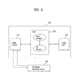
- FIG. 3 is a view showing a system in which a broadcasting receiver is connected to the IP address allocation server;
- FIG. 4 is a flowchart illustrating a method of controlling the broadcasting receiver
- FIG. 5 is a view showing the form of a message which is exchanged between the IP process and the IP address allocation server;
- FIG. 6 is a characteristic view of a format of transmitted/received message shown in FIG. 5 ;
- FIG. 7 is a view illustrating a process of allocating IP addresses to internal processes in the host
- FIG. 8 is a view showing internal process communication between a host process and an IP process in the host.
- FIG. 9 is a view showing the configuration of the broadcasting receiver.
- FIG. 1 is a conceptual diagram of a broadcasting network in digital cable broadcasting.
- a cable headend hereinafter, referred to as a headend
- a plant can receive a broadcasting signal via various communication networks.
- the headend can transmit the cable broadcasting signal, which is received via the various communication networks, to a cable broadcasting receiver via a network including a node.
- the cable broadcasting receiver can receive the broadcasting signal from the headend or transmit a specific signal to the headend. At this time, the transmission/reception is realized via a cable network shown in FIG. 1 , which can bidirectionally transmit data.
- a host can be connected to peripheral devices such as a digital television receiver, a DVD player, a digital camcorder, and a set top box via various types of interfaces.
- peripheral devices such as a digital television receiver, a DVD player, a digital camcorder, and a set top box via various types of interfaces.
- the host can receive and process a cable broadcasting service from the headend, as described above.
- the host downloads a monitor application, various applications, or an opencable application platform (OCAP)-Java application such as an electronic program guide (EPG) from the remote headend via the cable network and operates the application on its system.
- OCAP opencable application platform
- EPG electronic program guide
- a security module is installed in the receiver which receives the broadcasting signal.
- the broadcasting receiver is composed of the host and the security module.
- the host and the security module exchange an encrypted broadcasting signal or other data, for security.
- the headend and the host use IP network communication, for two-way communication.
- the host receives an IP address in order to transmit data via an up channel.
- FIG. 2 is a view showing the flow of data between an IP process of the host and an IP address allocation server.
- the IP process and the IP address allocation server transmit/receive messages in time-series order.
- the IP process indicates a process for performing the IP network communication in the host and may be, for example, a process for receiving the IP address according to a dynamic host configuration protocol (DHCP).
- DHCP dynamic host configuration protocol
- the IP address allocation server may be called a DHCP server and the IP process may be called a DHCP client.
- the DHCP is shown for convenience of description.
- the IP process may be a process for the DHCP client or a processor for performing the process.
- the IP process transmits a DHCP discover message in order to search for a usable IP address allocation server (1).
- the IP address allocation server which receives the DHCP message transmits a DHCP offer message to the IP process in response to the DHCP discover message (2).
- the IP process receives the DHCP offer message and transmits a DHCP request, which is an IP address request message, to the IP address allocation server (3).
- the IP address allocation server which receives the DHCP request message transmits a DHCP ACK, which is a response message, to the IP process (4).
- FIG. 3 is a view showing a system in which the broadcasting receiver is connected to the IP address allocation server.
- the cable broadcasting receiver 300 includes a cable modem 310, a host 320 and a cable card 330.
- the IP address allocation server 350 is connected to the cable modem 310 and performs network communication with the cable broadcasting receiver 300 via a down channel and an up channel.
- the cable modem is an example of a cable communication unit.
- the host may perform a host process for controlling a variety of hardware of the host and an IP process for performing the IP network communication and may include processors for implementing the host process and the IP process.
- the processor for performing the host process and the processor for performing the IP process may be equal physically to each other.
- the IP process may be a DHCP client and the IP address allocation server may be a DHCP server.
- all the cable modem 310, the host 320 and the cable card 330 require the respective IP addresses.
- the cable modem 310 may receive the IP address from the IP address allocation server through the procedure shown in FIG. 2 and may transmit information via the up channel using the received IP address. That is, the cable modem 310 searches for the IP address allocation server 350, is connected to the IP address allocation server 350, transmits identification information of the cable modem 310 to the IP address allocation server 350, and makes a request for an IP address. Then, the IP address allocation server 350 transmits the IP address for the cable modem to the cable modem 310. Accordingly, the IP network communication between the cable modem 310 and the IP address allocation server 350 becomes possible. That is, the two-way communication between the broadcasting receiver and the IP address allocation server becomes possible.
- the cable modem 310 transmits a "2-way-OK" message indicating that the two-way communication is possible to the host 320.
- the host 320 operates the IP process for the host in order to obtain the IP address for the host.
- the host 320 operates the IP process and receives the IP address for the host from the IP address allocation server 350 via the cable modem 310 in a method similar to the method of acquiring the IP address by the cable modem 310.
- FIG. 4 is a flowchart illustrating a method of controlling the broadcasting receiver.
- the method of controlling the broadcasting receiver includes receiving identification information of the cable card (S41), transmitting the identification information to the IP address allocation server (S42), receiving an IP address for the cable card from the IP address allocation server (S43), and transmitting the received IP address to the cable card (S44).
- the host receives the identification information of the cable card via a cable card interface (CCIF).
- CCIF cable card interface
- the identification information of the cable card includes an identification number of the cable card.
- the host may further receive option data from the cable card.
- the identification number of the cable card is an identifier for identifying the cable card and includes a media access control (MAC) or a serial number of the cable card.
- the option data indicates vendor information of the cable card.
- the vendor information is information on a manufacturer of the card.
- the host sends the identification information received from the cable card to the IP address allocation server. That is, the IP process for the cable card of the host includes the identification information received from the cable card in a message and transmits the message to the IP address allocation server.
- the IP process which receives the IP address for the host and the IP process which receives the IP address for the cable card are independently operated.
- the host operates a DHCP process for acquiring the IP address of the host and a DHCP process for acquiring the IP address of the cable card.
- the IP process which receives the IP address for the cable card sends the identification information of the cable card to the IP address allocation server so as to represent that the requested IP address is the IP address for the cable card.
- the host receives the IP address for the cable card from the IP address allocation server, that is, the IP address allocation server, which receives the request for the IP address for the cable card of the host, transmits the IP address for the cable card to the host.
- the IP address allocation server that is, the IP address allocation server, which receives the request for the IP address for the cable card of the host, transmits the IP address for the cable card to the host.
- the IP address includes network information for network communication and may include all the IP address, a sub net address, a gateway, a bns and a domain name.
- the host informs the cable card of the IP address received from the IP address allocation server, that is, informs the cable card of the IP address of the cable card via the CCIF.
- the host transmits a rejection message indicating that the IP address cannot be allocated to the cable card.
- the IP process of the host determines whether or not the IP address can be allocated and sends the rejection message to the host process. Then, the host process can transmit the message to the cable card.
- FIG. 5 is a view showing the form of a message which is exchanged between the IP process and the IP address allocation server.
- an example of the message includes an eth header, an IP header, an UDP header and a DHCP message.
- the eth header is an example of a header for identifying a physical interface (for example ethernet header). That is, in the embodiment of the present invention, an interface which is used to acquire the IP address of the cable card is an interface of the host, and information for identifying the interface of the host is included in a message including the eth header.
- a header for identifying a physical interface for example ethernet header.
- the IP header and the UDP header indicate encapsulation of a message using a communication protocol used for transmission/reception of the message.
- the header may vary according to the used communication protocol.
- the DHCP message is a payload including actual data. If the message is a message transmitted from the host to the IP address allocation server, the message includes the identification information of the cable card. If the message is a message transmitted from the IP address allocation server to the host, the message may include network information for the cable card allocated to the cable card.
- FIG. 6 shows a format of transmitted/received message shown in FIG. 5 in detail.
- a chaddr field to which a hardware address is added may include the identification number of the cable card and the option data of the cable card may be included in an option field.
- the IP address which is allocated to the cable card by the IP address allocation server is included in a yiaddr field.
- FIG. 7 is a view illustrating an example of an overall process of allocating IP addresses to internal processes in the host.
- the host process receives the MAC address and the option data of the cable card from the cable card via the CCIF.
- the host process receives a message including the MAC address and the option data from the cable card and sends the received message to the IP address allocation server via the DHCP client which is the IP process.
- the message in which the MAC address and the option data of the cable card are included by the IP process, is sent to the IP address allocation server via the physical interface of the host.
- the physical interface identifier of the host, the MAC address and the option information of the cable card are included in the message.
- the IP process receives the IP address for the cable card from the IP address allocation server and sends the received IP address for the cable card to the host process.
- the host process sends the received IP address for the cable card to the cable card via the CCIF.
- FIG. 8 is a view showing internal process communication between the host process and the IP process in the host.
- examples of the communication between the internal processes may include a file system, a pipe and a unix socket.
- the host process and the IP process can be operated together and the cable card acquires the IP address via the two processes.
- the internal process communication between the host process and the IP process is required.
- the communication between the internal processes is necessary when a message or an event is exchanged between individual processes with respect to information which is internally implemented.
- the file system indicates that a file generated in a process is formed at the outside of the process and is sent to another process.
- the pipe indicates that two processes are connected to each other such that an output of one process can be used as an input of the other process.
- the unix socket directly connects the host process to the IP address.
- the host process may use all the file system, the pipe and the unix socket.
- the file system is used. Both a command and other message may be communicated using the unix socket. Both the option information and other message may be communicated using the unix socket.
- the IP process may be stopped or re-operated according to an operation mode of the cable card.
- the operation mode of the cable card largely includes three modes, that is, an out-of-band (OOB) mode, a DOCSIS set-top box gateway (DSG) 2-way mode and a DSG 1-way mode.
- OOB out-of-band
- DSG DOCSIS set-top box gateway
- DSG 1-way mode a DSG 1-way mode.
- the OOB mode since the cable card functions as a link modem such that the IP address is transmitted from the host to the cable card, the IP process of the host may not be operated.
- the DSG 1-way mode since the two-way communication is interrupted, the IP communication is impossible. Accordingly, even in this state, the IP process of the host may not be operated. If the operation mode of the cable card is switched from the OOB mode or the DSG 1-way mode to the DSG 2-way mode, the IP process is newly operated or the interrupted IP process of the host is re-operated.
- the IP process which is being operated is killed. If the operation mode is switched to the 2-way mode, the IP process is re-operated.
- the host executes a host control program, a great amount of threads including a new process or a process which is a portion of the program are generated. If the new process is generated during the operation of the host process, a system load may be increased. For example, since the host process such as the Linux process is bulky and all the threads which have been executed are copied to the new process, the resource of the system is wasted.
- IP process If the IP process is killed in order to stop the operation of the process, the process may not be clearly erased and Zombie processes may be generated. If the IP process continuously perform operations fork() and kill() on an embedded system, the stability of the system may deteriorate.
- the IP process of the host which was run once, is controlled such that the effect obtained when the IP process is killed, is obtained even in a state in which the IP process is not killed, even in a case that the mode is switched until the system is completed.
- the IP process is controlled to three states including a "RUNNING" state, a "SUSPEND” state and a "RESUME” state via the unix socket communication.
- the "SUSPEND” state indicates a state in which the IP process is continuously operated but no action is internally taken in a waiting state until the operation of the IP process is normally performed or a "RESUME" command is received according to the mode.
- the host adequately controls the IP process according to the operation mode of the cable card. For example, when the mode is switched to the OOB mode or the DSG 1-way mode, the host sends a "SUSPEND" command to the IP processes for the host and the cable card via the internal process communication such that the operation of the IP process is immediately stopped.
- the cable modem sends a "2-way OK” message
- the host sends the "RESUME” command to the IP process for the host in order to acquire the IP address of the host.
- the IP process is controlled to be resumed in an INIT-REBOOT state.
- the host sends a "RESUME" command to the IP process for the cable card.
- the IP process for the cable card is also resumed in the INIT-REBOOT state.
- the state of the IP process is switched to the "RUNNING" state.
- a case where the IP process is not operated or a case where the IP process is operated once while the switching is performed between the "SUSPEND" state and the "RUNNING" state are distinguished from each other. Otherwise, many IP processes may be generated on the system.
- the IP process In order to determine whether or not the IP process is operated, it may be determined whether a Pid file is generated while the IP process is performed or it may be determined whether or not the unix socket communication is normally operated.
- the Pid file for the IP processes and files which are generated while performing the IP process may be stored in a memory, may be automatically deleted when power is turned off, or may be deleted at the time of the completion of the system in a case of being stored in a flash memory.
- the IP process may send the IP address to the host process via the internal communication when receiving the IP address for the cable card from the IP address allocation server, and the host process may transmit the IP address for the cable card to the cable card via the CCIF.
- the host process may stop or operate the IP process so as to stabilize the system.
- vendor specific information which is the vendor information of the cable card
- the DHCP client may read this file and include option information related thereto in the option field of the DHCP message.
- the DHCP client may make a request for the option information related thereto to the host process via the unix socket interface and include the option information in the option field of the DHCP message.
- FIG. 9 is a view showing the configuration of the broadcasting receiver.
- a host 900 receives a stream broadcasting signal from the headend and transmits the stream broadcasting signal to a security module 950.
- the cable card is used as an example of the security module.
- the broadcasting signal which is restrictively received by the cable card 950 is transmitted to the host 900 again to allow a viewer to view the broadcasting.
- the broadcasting receiver includes the host 900, a cable communication unit 940 and the cable card 950. At this time, the host operates the process for acquiring the IP address of the cable card.
- the digital broadcasting receiver includes the host 900, the cable communication unit 940 and the cable card 950.
- the host 900 includes a tuner 902, a demultiplexer 904, an audio decoder 906, a video decoder 908, an output unit 910, an additional information processor 912, a conditional access module (CAS) module 914, a key input unit 919, a card interface unit 918, a memory 920, and a controller 930.
- CAS conditional access module
- the tuner 902 seeks a broadcasting channel selected by a user. If the user changes a viewing channel, a frequency corresponding thereto is selected. A signal according to the selected frequency is input to a demodulator (not shown) which demodulates the signal in a vestigal side band (VSB) or quadrature amplitude modulation (QAM) scheme, and the demodulated signal is converted into a digital signal by an A/D converter (not shown).
- VSB vestigal side band
- QAM quadrature amplitude modulation
- the demultiplexer 904 demultiplexes a time-multiplexed transport stream into video, audio and additional information signals.
- the audio decoder 906 decodes the audio signal output from the demultiplexer 904 and outputs the decoded signal to the output unit 910.
- the video decoder 908 decodes the video signal outputted from the demultiplexer 904 and the output unit 910 displays the video signal.
- the CAS module 914 extracts entitlement control message (ECM) packet indicator (PID) and a local transport stream ID (LTSID) from the information analyzed by the additional information processor 912.
- ECM entitlement control message
- LTSID local transport stream ID
- a desired command of the user is input to the key input unit 919 and the control unit 930 controls the whole operations of the components of the digital broadcasting receiver.
- the controller 930 performs a restrictive reception function between the cable card 950 and the host 900 and a duplication restriction process.
- the controller 930 divides the received digital broadcasting signal into a main stream and an extra stream, determines whether or not the streams are scrambled, and descrambles a scrambled stream.
- the controller 930 operates the host process and the IP process and controls the acquisition of the IP address of the cable card.
- the host process and the IP process may be performed by the controller 930.
- the memory 920 stores and extracts necessary information according to a control signal of the controller 930.
- information on the stream which is subjected to the determination as to whether or not the stream is scrambled is stored by the control signal of the controller 930.
- the cable card 950 is inserted into the card interface unit 918.
- the card interface unit 918 may be positioned in any one or both of the host and the security module 950.
- the card interface unit 918 functions as a data communication path when the controller 930 reads the identification information and the option information of the cable card from the cable card, and the host functions as a data communication path for transmitting the IP address for the cable card received from the IP address allocation server to the cable card.
- the cable communication unit 940 performs the network communication.
- the cable communication unit 940 is connected to the IP address allocation server so as to transmit/receive a message to/from the IP address allocation server.
- Examples of the cable communication unit include a cable modem.
- a descrambling module is included in the cable card and the cable card may be attached/detached to/from the host.
- the broadcasting signal from a broadcasting station is descrambled by the descrambling module of the cable card and is provided to the user.
- the descrambling module may be included in the host without the cable card and the descrambling module may be included in the host when the descrambling module is downloaded from the broadcasting station.
- the descrambling module which is downloaded from the broadcasting station is stored in a predetermined memory of the host.
- a method of downloading the descrambling module may be, for example, performed by automatically downloading a conditional access (CA) image from the headend when a security processor which is previously mounted in a set top box is connected to a network.
- CA conditional access
Landscapes
- Engineering & Computer Science (AREA)
- Signal Processing (AREA)
- Multimedia (AREA)
- Computer Networks & Wireless Communication (AREA)
- Two-Way Televisions, Distribution Of Moving Picture Or The Like (AREA)
- Small-Scale Networks (AREA)
- Data Exchanges In Wide-Area Networks (AREA)
Claims (16)
- Verfahren zum Durchführen der Kommunikation zwischen einem Internetprotokoll-, IP-Adressen-Zuweisungsserver und einer Kabelkarte (950) für einen Host (900), wobei das Verfahren aufweist:Erfassen (S41) von Identifikationsinformationen der Kabelkarte (950) und Übertragen (S42) einer Nachricht einschließlich der Identifikationsinformationen der Kabelkarte (950) an den IP-Adressen-Zuweisungsserver durch den Host (900);Empfangen (S43) einer IP-Adresse für die Kabelkarte (950) von dem IP-Adressen-Zuweisungsserver durch den Host (900);Senden (S44) der empfangenen IP-Adresse für die Kabelkarte (950) an die Kabelkarte (950) durch den Host (900);dadurch gekennzeichnet, dass das Verfahren ferner das Ausführen eines Hostprozesses zum Steuern eines internen Systems des Hosts (900) und/oder das Ausführen eines IP-Prozesses zum Erfassen der IP-Adresse von dem IP-Adressen-Zuweisungsserver aufweist, undwobei der IP-Prozess unterbrochen wird, wenn eine Kommunikationsbetriebsart zwischen dem Host (900) und der Kabelkarte (950) ein Außerbandbetrieb, OOB-Betriebsart oder eine DOCSIS-Set-Top-Box-Gateway-Betriebsart, DSG-Einwegbetriebsart ist, und der IP-Prozess wieder aufgenommen wird, wenn die Kommunikationsbetriebsart zwischen dem Host (900) und der Kabelkarte (950) eine DSG-Zweirichtungsbetriebsart ist.
- Verfahren nach Anspruch 1, wobei die Identifikationsinformation der Kabelkarte (950) eine Identifikationsnummer der Kabelkarte (950) ist.
- Verfahren nach Anspruch 2, wobei die Identifikationsnummer der Kabelkarte (950) eine Medienzugriffssteuerungs-, MAC-Adresse der Kabelkarte (950) oder eine Seriennummer der Kabelkarte (950) ist.
- Verfahren nach Anspruch 1, wobei die Nachricht Informationen über einen Hersteller der Kabelkarte (950) umfasst.
- Verfahren nach Anspruch 1, wobei die Nachricht beim Übertragen der Nachricht an den I P-Adressen-Zuweisungsserver in einer Form eines dynamischen Hostkonfigurationsprotokolls DHCP übertragen wird.
- Verfahren nach Anspruch 1, wobei der IP-Prozess über Socket-Kommunikation auf einen "RUNNING" (laufenden) Zustand, einen "SUSPEND" (unterbrochenen) Zustand und einen "RESUME" (wieder aufgenommenen) Zustand gesteuert wird.
- Verfahren nach Anspruch 1, wobei der Hostprozess und der IP-Prozess unter Verwendung eins Dateisystems, einer Leitung oder eines Socket miteinander kommunizieren.
- Verfahren nach Anspruch 1, das ferner das Durchführen der Kommunikation durch die Kabelkarte (950) unter Verwendung der IP-Adresse für die Kabelkarte (950) aufweist.
- Rundfunkempfänger, der mit einem IP-Adressen-Zuweisungsserver kommuniziert, wobei der Rundfunkempfänger aufweist:eine Kabelkarte (950), die konfiguriert ist, um eine Anforderung einer IP-Adresse der Kabelkarte (950) zu senden;einen Host (900), der konfiguriert ist, um mit einem IP-Adressen-Zuweisungsserver zu kommunizieren, die Anforderung von der Kabelkarte (950) zu empfangen, eine Nachricht mit Identifikationsinformationen der Kabelkarte (950) an den IP-Adressen-Zuweisungsserver zu übertragen, die IP-Adresse der Kabelkarte (950) von dem IP-Adressen-Zuweisungsserver zu empfangen und die empfange IP-Adresse an die Kabelkarte (950) zu übertragen,eine Kartenschnittstelle (918), die konfiguriert ist, um die Kommunikation zwischen der Kabelkarte (950) und dem Host (900) durchzuführen; undeine Kabelkommunikationseinheit (940), die konfiguriert ist, um die Kommunikation zwischen dem Host (900) und dem IP-Adressen-Zuweisungsserver durchzuführen,dadurch gekennzeichnet, dassder Host (900) ferner konfiguriert ist, um einen Hostprozess zum Steuern eines internen Systems des Hosts (900) auszuführen und einen IP-Prozess zum Erfassen der IP-Adresse von dem IP-Adressen-Zuweisungsserver auszuführen, undwobei der IP-Prozess unterbrochen wird, wenn eine Kommunikationsbetriebsart zwischen dem Host (900) und der Kabelkarte (950) ein Außerbandbetrieb, OOB-Betriebsart oder eine DOCSIS-Set-Top-Box-Gateway-Betriebsart, DSG-Einwegbetriebsart ist, und der IP-Prozess wieder aufgenommen wird, wenn die Kommunikationsbetriebsart zwischen dem Host (900) und der Kabelkarte (950) eine DSG-Zweirichtungsbetriebsart ist.
- Rundfunkempfänger nach Anspruch 9, wobei die Identifikationsinformation der Kabelkarte (950) eine Identifikationsnummer der Kabelkarte (950) ist.
- Rundfunkempfänger nach Anspruch 10, wobei die Identifikationsnummer der Kabelkarte (950) eine Medienzugriffssteuerungs-, MAC-Adresse der Kabelkarte (950) oder eine Seriennummer der Kabelkarte (950) ist.
- Rundfunkempfänger nach Anspruch 9, wobei die Nachricht Informationen über einen Hersteller der Kabelkarte (950) umfasst.
- Rundfunkempfänger nach Anspruch 9, wobei die Nachricht von dem Host (900) in der Form eines dynamischen Hostkonfigurationsprotokolls DHCP übertragen wird.
- Rundfunkempfänger nach Anspruch 9, wobei der IP-Prozess über Socket-Kommunikation auf einen "RUNNING" (laufenden) Zustand, einen "SUSPEND" (unterbrochenen) Zustand und einen "RESUME" (wieder aufgenommenen) Zustand gesteuert wird.
- Rundfunkempfänger nach Anspruch 9, wobei der Hostprozess und der IP-Prozess unter Verwendung eins Dateisystems, einer Leitung oder eines Socket miteinander kommunizieren.
- Rundfunkempfänger nach Anspruch 9, wobei die Kabelkarte (950) die Kommunikation unter Verwendung der empfangenen IP-Adresse durchführt.
Applications Claiming Priority (1)
| Application Number | Priority Date | Filing Date | Title |
|---|---|---|---|
| KR1020060130997A KR101342363B1 (ko) | 2006-12-20 | 2006-12-20 | 방송 수신 장치 및 이를 제어하는 방법 |
Publications (3)
| Publication Number | Publication Date |
|---|---|
| EP1959644A2 EP1959644A2 (de) | 2008-08-20 |
| EP1959644A3 EP1959644A3 (de) | 2008-08-27 |
| EP1959644B1 true EP1959644B1 (de) | 2011-11-30 |
Family
ID=39544880
Family Applications (1)
| Application Number | Title | Priority Date | Filing Date |
|---|---|---|---|
| EP07123049A Not-in-force EP1959644B1 (de) | 2006-12-20 | 2007-12-12 | Rundfunkempfänger und Kommunikationsverfahren mit dem Rundfunkempfänger |
Country Status (4)
| Country | Link |
|---|---|
| US (1) | US7900234B2 (de) |
| EP (1) | EP1959644B1 (de) |
| KR (1) | KR101342363B1 (de) |
| CN (1) | CN100571279C (de) |
Families Citing this family (2)
| Publication number | Priority date | Publication date | Assignee | Title |
|---|---|---|---|---|
| US9197919B2 (en) | 2013-06-12 | 2015-11-24 | Mediacom Communications Corporation | Video on demand using combined host and client addressing |
| KR20140146400A (ko) * | 2013-06-17 | 2014-12-26 | 삼성전자주식회사 | 방송수신장치 및 그 제어방법 |
Family Cites Families (23)
| Publication number | Priority date | Publication date | Assignee | Title |
|---|---|---|---|---|
| US5768539A (en) * | 1994-05-27 | 1998-06-16 | Bell Atlantic Network Services, Inc. | Downloading applications software through a broadcast channel |
| US6230326B1 (en) * | 1998-07-30 | 2001-05-08 | Nortel Networks Limited | Method and apparatus for initialization of a cable modem |
| JP2000196631A (ja) | 1998-12-24 | 2000-07-14 | Toshiba Corp | ケーブルモデムシステム及びipアドレス動的割当装置 |
| US6785564B1 (en) * | 1999-08-31 | 2004-08-31 | Broadcom Corporation | Method and apparatus for latency reduction in low power two way communications equipment applications in hybrid fiber coax plants |
| US7150017B1 (en) * | 2000-08-29 | 2006-12-12 | International Business Machines Corporation | System and method for scheduling digital information transmission and retransmission on a network during time slots |
| WO2002065771A1 (en) * | 2001-02-09 | 2002-08-22 | Quadriga Technology Limited | System for and method of distributing television, video and other signals |
| CN1144421C (zh) | 2001-04-25 | 2004-03-31 | 数位联合电信股份有限公司 | 双向缆线网络地址管理系统及方法 |
| US20030048380A1 (en) * | 2001-09-12 | 2003-03-13 | Yuriko Tamura | Self provisioning Set-Top Box |
| JP3687599B2 (ja) | 2001-12-06 | 2005-08-24 | ソニー株式会社 | 通信装置および方法、記録媒体、並びにプログラム |
| JP3948277B2 (ja) | 2001-12-27 | 2007-07-25 | 富士ゼロックス株式会社 | 外部ネットワーク接続のための設定情報割当方法 |
| KR100934138B1 (ko) | 2002-05-06 | 2009-12-29 | 퀄컴 인코포레이티드 | 무선 통신 장치의 ip 어드레스를 등록하기 위한 시스템및 방법 |
| US7805746B2 (en) * | 2003-03-14 | 2010-09-28 | Tvworks, Llc | Optimized application on-the-wire format for construction, delivery and display of enhanced television content |
| US7958505B2 (en) * | 2003-06-20 | 2011-06-07 | Ericsson Television, Inc | Systems and methods for distributing software for a host device in a cable system |
| US7694323B2 (en) * | 2004-01-12 | 2010-04-06 | Time Warner Cable, Inc. | Technique for providing security measures for communications device connectable to a communications network |
| JP4257238B2 (ja) * | 2004-03-15 | 2009-04-22 | 日本電気株式会社 | Ipアドレス自動付与方法/プログラム/記録媒体/装置/システム、シャーシ管理装置、制御カード |
| WO2006016760A1 (en) * | 2004-08-10 | 2006-02-16 | Samsung Electronics Co., Ltd. | Apparatus and method for diagnosing cablecard-related status and performing proper processing, opencable host, and opencable reception apparatus |
| KR100636321B1 (ko) * | 2004-10-18 | 2006-10-18 | 삼성전자주식회사 | 다중 dsg 채널을 갖는 오픈케이블 디지털 방송시스템과 그 디지털 방송 시스템에서의 홈 dsg 채널획득 방법 |
| EP1834483B1 (de) * | 2004-12-30 | 2016-04-13 | Telecom Italia S.p.A. | Verfahren und system zum empfang multimedia inhalten auf der wiedergabeeinheit eines anwender via kommunikationsendgerät |
| US20060159122A1 (en) * | 2005-01-18 | 2006-07-20 | Texas Instruments Incorporated | Providing TDM channels to locations connected by networks implemented on broadcast medium |
| WO2006077720A1 (ja) * | 2005-01-18 | 2006-07-27 | Matsushita Electric Industrial Co., Ltd. | 画像合成装置 |
| US7594252B2 (en) * | 2005-03-01 | 2009-09-22 | Time Warner Cable, Inc. | Early warning fault identification and isolation system for a two-way cable network |
| US7810127B2 (en) * | 2005-08-31 | 2010-10-05 | Time Warner Cable, Inc. | System and method for evaluating the operational status of a STB in a cable network |
| KR20070079229A (ko) * | 2006-02-01 | 2007-08-06 | 엘지전자 주식회사 | 방송 수신기, 진단 정보 데이터 구조 및 진단 정보 표출방법 |
-
2006
- 2006-12-20 KR KR1020060130997A patent/KR101342363B1/ko not_active Expired - Fee Related
-
2007
- 2007-12-11 US US12/000,326 patent/US7900234B2/en not_active Expired - Fee Related
- 2007-12-12 EP EP07123049A patent/EP1959644B1/de not_active Not-in-force
- 2007-12-20 CN CNB2007101600188A patent/CN100571279C/zh not_active Expired - Fee Related
Also Published As
| Publication number | Publication date |
|---|---|
| US20080155640A1 (en) | 2008-06-26 |
| CN100571279C (zh) | 2009-12-16 |
| KR101342363B1 (ko) | 2013-12-16 |
| US7900234B2 (en) | 2011-03-01 |
| KR20080057561A (ko) | 2008-06-25 |
| EP1959644A2 (de) | 2008-08-20 |
| EP1959644A3 (de) | 2008-08-27 |
| CN101207790A (zh) | 2008-06-25 |
Similar Documents
| Publication | Publication Date | Title |
|---|---|---|
| US7219367B2 (en) | Backup communication modes | |
| US9706243B2 (en) | Broadcasting receiver and a method of determining an operation mode of broadcasting receiver | |
| CA2498280C (en) | Adaptive communication modes | |
| JP2008310553A (ja) | デジタル放送受信機及びデジタル放送受信システム | |
| US7650622B2 (en) | Interactive session establishment based on initiation failure detection | |
| US20090133056A1 (en) | Broadcasting system and method of processing emergency alert message | |
| US20080168513A1 (en) | Broadcast receiver and method for transmitting reception status of the broadcast receiver | |
| EP1959644B1 (de) | Rundfunkempfänger und Kommunikationsverfahren mit dem Rundfunkempfänger | |
| US8086742B2 (en) | Broadcasting receiver and method of interfacing resource information between a host device and a POD, sending host device resource information and obtaining host device resource information | |
| US8572667B2 (en) | Host device interfacing with a point of deployment (POD) and a method of processing digital video recorder (DVR) status information | |
| US7924701B2 (en) | Data transmitting and receiving method and broadcasting receiver | |
| JP2007201911A (ja) | ケーブルテレビ受信システム | |
| US20070106809A1 (en) | Data structure and method for initiating a flow over an extended channel | |
| JP5349660B2 (ja) | デジタル放送受信機及びデジタル放送受信システム | |
| KR20080108701A (ko) | 데이터 송수신 방법 및 방송 수신 장치 | |
| KR20080108702A (ko) | 데이터 송수신 방법 및 방송 수신 장치 |
Legal Events
| Date | Code | Title | Description |
|---|---|---|---|
| PUAI | Public reference made under article 153(3) epc to a published international application that has entered the european phase |
Free format text: ORIGINAL CODE: 0009012 |
|
| PUAL | Search report despatched |
Free format text: ORIGINAL CODE: 0009013 |
|
| 17P | Request for examination filed |
Effective date: 20071212 |
|
| AK | Designated contracting states |
Kind code of ref document: A2 Designated state(s): AT BE BG CH CY CZ DE DK EE ES FI FR GB GR HU IE IS IT LI LT LU LV MC MT NL PL PT RO SE SI SK TR |
|
| AX | Request for extension of the european patent |
Extension state: AL BA HR MK RS |
|
| AK | Designated contracting states |
Kind code of ref document: A3 Designated state(s): AT BE BG CH CY CZ DE DK EE ES FI FR GB GR HU IE IS IT LI LT LU LV MC MT NL PL PT RO SE SI SK TR |
|
| AX | Request for extension of the european patent |
Extension state: AL BA HR MK RS |
|
| 17Q | First examination report despatched |
Effective date: 20090311 |
|
| AKX | Designation fees paid |
Designated state(s): DE FR GB IT |
|
| GRAP | Despatch of communication of intention to grant a patent |
Free format text: ORIGINAL CODE: EPIDOSNIGR1 |
|
| RAP1 | Party data changed (applicant data changed or rights of an application transferred) |
Owner name: LG ELECTRONICS INC. |
|
| GRAS | Grant fee paid |
Free format text: ORIGINAL CODE: EPIDOSNIGR3 |
|
| GRAA | (expected) grant |
Free format text: ORIGINAL CODE: 0009210 |
|
| AK | Designated contracting states |
Kind code of ref document: B1 Designated state(s): DE FR GB IT |
|
| REG | Reference to a national code |
Ref country code: GB Ref legal event code: FG4D |
|
| REG | Reference to a national code |
Ref country code: DE Ref legal event code: R096 Ref document number: 602007019037 Country of ref document: DE Effective date: 20120126 |
|
| PG25 | Lapsed in a contracting state [announced via postgrant information from national office to epo] |
Ref country code: IT Free format text: LAPSE BECAUSE OF FAILURE TO SUBMIT A TRANSLATION OF THE DESCRIPTION OR TO PAY THE FEE WITHIN THE PRESCRIBED TIME-LIMIT Effective date: 20111130 |
|
| PLBE | No opposition filed within time limit |
Free format text: ORIGINAL CODE: 0009261 |
|
| STAA | Information on the status of an ep patent application or granted ep patent |
Free format text: STATUS: NO OPPOSITION FILED WITHIN TIME LIMIT |
|
| 26N | No opposition filed |
Effective date: 20120831 |
|
| REG | Reference to a national code |
Ref country code: DE Ref legal event code: R097 Ref document number: 602007019037 Country of ref document: DE Effective date: 20120831 |
|
| REG | Reference to a national code |
Ref country code: FR Ref legal event code: PLFP Year of fee payment: 9 |
|
| REG | Reference to a national code |
Ref country code: FR Ref legal event code: PLFP Year of fee payment: 10 |
|
| REG | Reference to a national code |
Ref country code: FR Ref legal event code: PLFP Year of fee payment: 11 |
|
| REG | Reference to a national code |
Ref country code: FR Ref legal event code: PLFP Year of fee payment: 12 |
|
| PGFP | Annual fee paid to national office [announced via postgrant information from national office to epo] |
Ref country code: DE Payment date: 20191105 Year of fee payment: 13 |
|
| PGFP | Annual fee paid to national office [announced via postgrant information from national office to epo] |
Ref country code: FR Payment date: 20191107 Year of fee payment: 13 |
|
| PGFP | Annual fee paid to national office [announced via postgrant information from national office to epo] |
Ref country code: GB Payment date: 20191106 Year of fee payment: 13 |
|
| REG | Reference to a national code |
Ref country code: DE Ref legal event code: R119 Ref document number: 602007019037 Country of ref document: DE |
|
| GBPC | Gb: european patent ceased through non-payment of renewal fee |
Effective date: 20201212 |
|
| PG25 | Lapsed in a contracting state [announced via postgrant information from national office to epo] |
Ref country code: FR Free format text: LAPSE BECAUSE OF NON-PAYMENT OF DUE FEES Effective date: 20201231 |
|
| PG25 | Lapsed in a contracting state [announced via postgrant information from national office to epo] |
Ref country code: GB Free format text: LAPSE BECAUSE OF NON-PAYMENT OF DUE FEES Effective date: 20201212 Ref country code: DE Free format text: LAPSE BECAUSE OF NON-PAYMENT OF DUE FEES Effective date: 20210701 |