EP1959587B1 - Verfahren, vorrichtung und system zur bearbeitung von glasfaserleitungsfehlern - Google Patents
Verfahren, vorrichtung und system zur bearbeitung von glasfaserleitungsfehlern Download PDFInfo
- Publication number
- EP1959587B1 EP1959587B1 EP06828276.3A EP06828276A EP1959587B1 EP 1959587 B1 EP1959587 B1 EP 1959587B1 EP 06828276 A EP06828276 A EP 06828276A EP 1959587 B1 EP1959587 B1 EP 1959587B1
- Authority
- EP
- European Patent Office
- Prior art keywords
- optical
- amplifier
- signal
- fiber
- station
- Prior art date
- Legal status (The legal status is an assumption and is not a legal conclusion. Google has not performed a legal analysis and makes no representation as to the accuracy of the status listed.)
- Active
Links
- 239000013307 optical fiber Substances 0.000 title description 2
- 238000003672 processing method Methods 0.000 title 1
- 230000003287 optical effect Effects 0.000 claims description 168
- 239000000835 fiber Substances 0.000 claims description 79
- 238000000034 method Methods 0.000 claims description 50
- 238000011144 upstream manufacturing Methods 0.000 claims description 35
- 238000001514 detection method Methods 0.000 claims description 32
- 238000004891 communication Methods 0.000 claims description 30
- 230000001629 suppression Effects 0.000 claims description 18
- 239000004065 semiconductor Substances 0.000 claims description 4
- 229910052761 rare earth metal Inorganic materials 0.000 claims description 3
- 230000008859 change Effects 0.000 claims description 2
- 230000005281 excited state Effects 0.000 claims description 2
- 230000002441 reversible effect Effects 0.000 description 12
- 238000010586 diagram Methods 0.000 description 9
- 229910052691 Erbium Inorganic materials 0.000 description 8
- 238000012423 maintenance Methods 0.000 description 8
- 238000001069 Raman spectroscopy Methods 0.000 description 7
- -1 erbium ions Chemical class 0.000 description 7
- 230000004044 response Effects 0.000 description 4
- 230000005540 biological transmission Effects 0.000 description 3
- 230000000737 periodic effect Effects 0.000 description 3
- 230000009467 reduction Effects 0.000 description 3
- 238000004364 calculation method Methods 0.000 description 2
- 230000007274 generation of a signal involved in cell-cell signaling Effects 0.000 description 2
- 230000005283 ground state Effects 0.000 description 2
- 230000008569 process Effects 0.000 description 2
- 238000005086 pumping Methods 0.000 description 2
- 230000001360 synchronised effect Effects 0.000 description 2
- 230000002159 abnormal effect Effects 0.000 description 1
- 230000003321 amplification Effects 0.000 description 1
- 238000004458 analytical method Methods 0.000 description 1
- 238000006243 chemical reaction Methods 0.000 description 1
- 230000003247 decreasing effect Effects 0.000 description 1
- 230000007547 defect Effects 0.000 description 1
- 238000004090 dissolution Methods 0.000 description 1
- 238000005516 engineering process Methods 0.000 description 1
- UYAHIZSMUZPPFV-UHFFFAOYSA-N erbium Chemical compound [Er] UYAHIZSMUZPPFV-UHFFFAOYSA-N 0.000 description 1
- 238000002474 experimental method Methods 0.000 description 1
- RGNPBRKPHBKNKX-UHFFFAOYSA-N hexaflumuron Chemical compound C1=C(Cl)C(OC(F)(F)C(F)F)=C(Cl)C=C1NC(=O)NC(=O)C1=C(F)C=CC=C1F RGNPBRKPHBKNKX-UHFFFAOYSA-N 0.000 description 1
- 230000000977 initiatory effect Effects 0.000 description 1
- 230000007246 mechanism Effects 0.000 description 1
- 238000012986 modification Methods 0.000 description 1
- 230000004048 modification Effects 0.000 description 1
- 238000003199 nucleic acid amplification method Methods 0.000 description 1
- 230000005855 radiation Effects 0.000 description 1
Images

Classifications
-
- H—ELECTRICITY
- H04—ELECTRIC COMMUNICATION TECHNIQUE
- H04B—TRANSMISSION
- H04B10/00—Transmission systems employing electromagnetic waves other than radio-waves, e.g. infrared, visible or ultraviolet light, or employing corpuscular radiation, e.g. quantum communication
- H04B10/07—Arrangements for monitoring or testing transmission systems; Arrangements for fault measurement of transmission systems
- H04B10/075—Arrangements for monitoring or testing transmission systems; Arrangements for fault measurement of transmission systems using an in-service signal
-
- H—ELECTRICITY
- H04—ELECTRIC COMMUNICATION TECHNIQUE
- H04B—TRANSMISSION
- H04B10/00—Transmission systems employing electromagnetic waves other than radio-waves, e.g. infrared, visible or ultraviolet light, or employing corpuscular radiation, e.g. quantum communication
- H04B10/03—Arrangements for fault recovery
-
- H—ELECTRICITY
- H04—ELECTRIC COMMUNICATION TECHNIQUE
- H04B—TRANSMISSION
- H04B2210/00—Indexing scheme relating to optical transmission systems
- H04B2210/07—Monitoring an optical transmission system using a supervisory signal
- H04B2210/071—Monitoring an optical transmission system using a supervisory signal using alarms
Definitions
- the present invention relates to optical communication technologies, and more particularly, to a method for handling a fiber line fault, a method for restoring an optical communication system on the basis of the method for handling a fiber line fault, apparatuses and an optical communication system for suppressing downstream alarms induced by a fiber line fault.
- the power density of laser in the output direction is especially high, which greatly threatens human eyes.
- the wavelength of lasers used in the existing communication system is generally around 870nm, 1310nm and 1550nm, which are all beyond the wavelength range of visible light. Because it is invisible, the light beam has a greater possibility to hurt human eyes.
- EDFA Erbium-Doped Fiber Amplifier
- WDM Wavelength Division Multiplexing
- the output power of optical signals carried in fibers is even higher than that of conventional Synchronous Digital Hierarchy (SDH) devices.
- SDH Synchronous Digital Hierarchy
- such apparatuses as RAMAN amplifier may be introduced into the existing communication system, which makes the power of the optical signals carried in fibers of some systems reach or even exceed 30dBm. Such a high power of the optical signal greatly threatens the safety of operators and maintenance personnel of telecommunication system.
- the safety level of laser apparatus and device is defined in Standard IEC60825, which specifies the specific operational measure and safety identifier as well.
- the International Telecommunication Union-Telecommunication Standardization Sector (ITU-T) constitutes Standard G.664 for laser safety in communication system, and puts forward that an optical communication apparatus should be able to automatically reduce the output power to the safe power and even turn off the laser when a laser leakage occurs, which is expressed as the Automatic Power Reduction (APR) and the Automatic Power Shutdown (APSD) solution in G.664.
- APR Automatic Power Reduction
- APSD Automatic Power Shutdown
- the APR is implemented by adding link status detection components and laser output control components in optical communication devices.
- the link status detection component in a downstream station detects loss of optical power, and determines that there is a potential laser leakage on an upstream link.
- the output power in an upstream direction of the downstream station is reduced via the corresponding laser output control component.
- the upstream station detects power reduction of the downstream station, and reduces output power in the downstream direction accordingly to reduce hazards caused by the laser leakage.
- An APR procedure of a common optical amplifier in an optical communication system is described in detail as an example.
- the west optical amplifier of station A detects loss of the optical signal sent from station B by the link state detecting component, and determines that there is a potential laser leakage on the fiber from station B to station A.
- the potential laser leakage may also exist on the fiber from station A to station B, and therefore, the west optical amplifier of station A instructs the east optical amplifier of station A to reduce the output power to make the laser leakage on the fiber from station A to station B compatible with the safety level constituted by Standard IEC60825, thereby protecting the operator and maintenance personnel.
- the east optical amplifier of station B detects the power reduction or loss of the east optical signal.
- the east optical amplifier of station B performs the same procedure described above. In other words, the east optical amplifier of station B notifies the west optical amplifier of station B to reduce the output power to make the laser leakage from station A to station B compatible with the safety level constituted by Standard IEC60825.
- APSD The implementation procedure of APSD is similar to that of APR, and the difference is that the APSD solution is to directly shut down a laser or an optical amplifier, rather than reduce the output power to a preset power.
- the APR and the APSD of the existing communication apparatuses are basically implemented by detecting optical power.
- optical power output in its reverse direction is reduced or shut down at once, so the laser leakage in the reverse direction is ensured to meet the requirement of safety standard, and an opposite side device is also instructed to perform the protection procedure.
- the key of the APR and the APSD solutions is detecting whether the received optical power is below a certain threshold to decide whether there is a potential laser leakage on the fiber.
- the APR is unavailable with the optical power detection alone where RAMAN amplifiers or remotely-pumped amplifiers are applied.
- pump light of the RAMAN amplifier or the remotely-pumped amplifier is usually inputted into a transmission fiber in the reverse direction of signal light.
- a west fiber from station B to station A fails, e.g. breaks, and poses a potential laser leakage
- a west receiving side of station A always detects high optical power because a part of inputted pump light is reflected back and also a reversed stimulated Raman radiation generated in the same direction of the optical signals is received by station A. In such case, the optical power detection is insufficient for determining whether a network breaks and whether there is a potential laser leakage in a network correctly.
- Typical solutions include detecting fiber line faults with an optical monitor channel, judging fiber line faults by a majority voting mechanism of optical channels, and even judging fiber line faults according to an Optical Signal to Noise Ratio (OSNR) and an electronic Signal to Noise Ratio (SNR).
- OSNR Optical Signal to Noise Ratio
- SNR electronic Signal to Noise Ratio
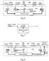
- upstream stations and downstream stations initiate restoration timing respectively, and launch a self restoration procedure when the restoration timing is up.
- the terminal that ends the restoration timing first sends a detection pulse.
- an amplifier in a direction of the detection pulse determines that an upstream link in the direction has been restored to normal, and sends the detection pulse along the same direction after amplifying the detection pulse.
- the detection pulse reaches a downstream terminal in the direction.
- the downstream terminal in the direction upon a receipt of the detection pulse, restores output power in a reverse direction.
- the light in the reverse direction is also amplified by amplifiers along the reverse direction. If the fiber line has been restored to normal, the terminal which sends the detection pulse detects the light in the reverse direction and thus determines that the network has been restored to normal, and the whole restoration procedure is accomplished.
- an upstream terminal initiates a restoration request first and sends a detection pulse at time point t1.
- the power of the detection pulse is lower than or equal to a safety power threshold.
- a downstream terminal detects the detection pulse and restores normal output power in a reverse fiber link at time point t2 after a time delay.
- the upstream terminal upon detection of the output power in the reverse direction at time point t3, learns that the network has been restored, and restores the output power of the detection pulse to normal output power. Hence the whole fiber link is restored to normal. If the fiber link has not been restored, the downstream terminal is unable to detect the detection pulse and does not open the light path in the reverse direction.
- the upstream terminal receives no feedback and thus stops sending the detection pulse when a waiting time is up. If the reverse fiber link has not been restored, the optical output by the downstream terminal is unable to reach the upstream terminal, and the upstream terminal shuts down the optical output when a waiting time is up. Consequently the downstream terminal shuts down optical output because no optical signal is received.
- the restoration procedure described in the ITU-T G.664 is performed between an upstream terminal and a downstream terminal. It is obvious that all amplifiers between the upstream terminal and the downstream terminal enter a failure state when one segment of the fiber line breaks. Because amplifiers adjacent to the broken segment shut down optical output once the fault is detected, which results in that even non-adjacent amplifiers consequentially shut down optical output. Because it takes time for each of the amplifier to restore normal output, hence a self restoration of the whole optical communication system needs a very long period of time which grows even longer when more cascade amplifiers are connected. Furthermore, once a fiber segment breaks, all neighboring amplifiers shut down output and all downstream amplifiers determine that the network fails and announce alarm because the downstream amplifiers receive no optical signal. As a result, all nodes in the network announce alarms, making it extremely difficult to locate the broken fiber segment in the whole network, and the abrupt alarms congest overhead channels and servers of the system, and the whole network is put in disturbance.
- US2005/185956 A1 discloses a method and apparatus for fault notification in an optical network.
- An exemplary process includes detecting at a node that at least a portion of a first unidirectional path of an optical circuit is down, where the first unidirectional path is originated from a first terminating node.
- the node signals the first terminating node by removing at least a portion of light of a second unidirectional path in an opposite direction of the first unidirectional path of the optical circuit, to indicate a path between the node and the first terminating node is down.
- GB 2 371 168 A discloses alarm signal suppression in telecommunications networks.
- traffic signals can be tagged to indicate that a fault condition has already been identified and reported.
- an alarm is suppressed if the tag indicates that the fault has already been reported.
- US2004/213567 A1 discloses an automatic power restoring method capable of reliably detecting continuity by the dissolution of a line fault, to restore the optical power, even in a structure including an optical amplification medium on an optical transmission path and an optical communication system using the method.
- EP1227606A1 discloses an optical repeating device.
- an optical transmitting apparatus and an optical repeating apparatus are provided.
- US 20040208519 A1 discloses a method and apparatus for controlling the power level of an optical signal includes detecting the loss of a supervisory signal counterpropagating in an optical fiber.
- KR20030094844A discloses a WDM system and an alarm generation suppressing and laser cut off method therefor.
- a failure detector detects whether each optical signal receiving channel has a failure.
- a maintenance signal inserter inserts a maintenance signal into a lower optical link device and an upper optical link device when a failure is detected from the channels.
- a maintenance signal detector detects the maintenance signal from the upper or the lower optical link device.
- An alarm suppresser inactivates a failure alarm generated in the lower optical link device in response to the detected maintenance signal.
- a laser cut off unit cuts off a laser of an optical amplifier connected to a front end of the optical link device where the failure is detected, in response to the maintenance signal.
- embodiments of the present invention provide a method for handling a fiber line fault, suppressing alarms from downstream stations and amplifiers which are not adjacent to the broken segment, and further suppressing APR or APSD procedures according to the alarms. Therefore, the time needed for a self restoration from the APR or APSD procedures is reduced.
- a method for handling a fiber line fault includes: loading, by an amplifier station, an indication signal carrying alarm suppression information onto an optical signal to be output to a downstream fiber upon detection of a fault on upstream fiber line in a double fiber two way optical communication system; and keeping, by a downstream amplifier station, a status of the downstream amplifier station in a normal working status upon a receipt of the optical signal with the indication signal, wherein keeping the status in the normal working status comprises at least keeping output power within a preconfigured level.
- the alarm suppression information comprises at least one of an ID of the amplifier station that outputs the alarm suppression information, a direction and an ID of a fiber segment with the upstream fiber fault.
- Embodiments of the present invention provide a double fiber two way optical communication system for suppressing downstream alarms induced by a fiber line fault, suppressing alarms from downstream stations and amplifiers which are not adjacent to the broken segment, and further reducing the time needed for a self restoration from the APR or APSD procedures.
- a double fiber two way optical communication system for suppressing downstream alarms induced by a fiber line fault includes at least two amplifier stations connected with a fiber, where a upstream amplifier station is configured to load an indication signal carrying alarm suppression information onto optical signal to be output, upon detection of a fiber line fault on a fiber link adjacent to the upstream station; a downstream amplifier station is configured to keep in a normal working status, upon a receipt of the indication signal carrying the alarm suppression information, wherein keeping the status in the normal working status comprises at least keeping output power within a preconfigured level.
- amplifiers adjacent to a broken segment indicates that a fault exists on an upstream fiber segment to downstream amplifiers, so as to solve the conventional problems including one fiber fault causes all amplifiers in a multiplex section to close, which results in a long restoration time, and all amplifiers announcing alarms which makes it extremely difficult to locate the network fault.
- downstream stations which are not adjacent to the broken segment are suppressed alarms, the APR or APSD procedures according to the alarms are suppressed, so that the downstream amplifiers do not all close and the time needed for a self restoration of the APR or APSD procedures is reduced.
- multiple stations are prevent from announcing alarms at the same time so that the alarm channel is not congested, work loads of network administrators are reduced, efficiency of the network administrator is improved, fiber faults may be located faster and more accurately, and the time needed for the self restoration from the fault is saved.
- the basic theory of a method provided by embodiments of the present invention for suppressing alarms of fiber line faults from downstream stations includes: when a fiber segment breaks, loading by a downstream station adjacent to the broken segment, upon a detection of a fiber line fault, an indication signal onto optical signals output to a downlink to indicate the fault on the upstream link.
- downstream stations which are not adjacent to the broken segment are suppressed alarms, and APR or APSD procedures invoked by receiving no optical signals at the downstream stations are stopped.
- amplifiers which are not adjacent to the broken segment are not closed when the fiber segment is being repaired, the time needed for self restoration is reduced significantly.
- a downstream amplifier adjacent to the broken segment detects a Loss of Signal (LOS), and determines that the upstream link may be broken and a potential laser leakage may exist. Therefore the downstream amplifier shuts down output in a reverse direction, i.e. the output from the amplifier to the direction of the broken segment.
- the downstream amplifier inserts a special indication signal (e.g. Forward Defect Indication, FDI) carrying specific information into the optical signals, and outputs the optical signals to the downlink for indicating a upstream fiber fault to the downstream amplifier stations so as to suppress alarms in the downstream amplifier stations.
- a special indication signal e.g. Forward Defect Indication, FDI
- the downstream stations Because the station adjacent to the broken segment is obliged to send optical signals to the downlink, the downstream stations always detect optical signals (no power loss) and thus does not determine that upstream signals are lost, nor the downstream stations perform APR or APSD procedures. The objectives of the present invention are thus achieved.
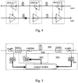
- FIG. 4 is a schematic diagram illustrating an optical communication system for suppressing downstream alarms induced by a fiber line faults in accordance with embodiments of the present invention.
- Station A includes an east amplifier EDFA1 and a west amplifier EDFA6
- station B includes an east amplifier EDFA2 and a west amplifier EDFA5
- station C includes an east amplifier EDFA3 and a west amplifier EDFA4.
- a east fiber segment between station A and station B breaks, the amplifier EDFA2 in east downstream station B detects that input signals of the amplifier EDFA2 are lost via embedded power or piloted signal detection device.
- the amplifier EDFA2 may shut down or reduce output of the amplifier EDFA5 which is in the same station serving in a reserve direction so as to avoid a potential laser leakage from station B to station A and instruct station A to shut down or reduce output of the amplifier EDFA1 to avoid a potential laser leakage from station A to station B.
- the above procedure is a conventional procedure and is not described in detail.
- the amplifier EDFA2 in station B After the amplifier EDFA2 in station B has detected loss of upstream signals, the amplifier EDFA2 still keeps output power within a certain level and inserts an indication signal carrying predetermined alarm suppression information into output optical signals.
- the amplifier EDFA3 in station C detects the optical signals and the inserted optical indication signal, and determines that a non-adjacent fiber segment breaks according to the piloted signal. Therefore station C keeps in a normal working status and announces no alarm.
- the downstream station C may also reduce the output power a little or take other actions, or forward the alarm suppression information to downstream stations without announcing alarm.
- station A may still keep output power within a certain level just as on the east link, and insert an indication signal carrying a predetermined alarm suppression information into output optical signals so that downstream stations of the station A on the east link announce no alarm and keep in a normal working status.
- all downstream amplifiers of station B are prevented from unwanted operations via inserting a special indication.
- the downstream amplifiers have always been in normal working status, the whole network is restored as soon as station A and station B is restored to the normal working status. Therefore, much less time is needed in comparison with the conventional restoration mode in which all stations need to be restored one by one.
- a scheme for loading an indication signal on a service optical channel in the procedure described above includes: loading a low amplitude intensity modulation signal on the service optical channel, i.e. the service optical channel is taken as a bearer for carrying the intensity modulation signal.
- the intensity modulation signal is received by a downstream station together with the signals on the service optical channel. And the downstream station determines that signals from the upstream station are normal upon a detection of the intensity modulation signal, and further determines that there is no failure on the fiber.
- An optical amplifier usually participates in power budgeting of a WDM system to meet requirements of optical multiplexing and de-multiplexing.
- the optical amplifiers used in the WDM system generally adopts an automatic gain control mode or an automatic power control mode to guarantee that power of optical signals amplified by the optical amplifier is kept steady on each optical channel and power of the single channel is free from being affected by increasing or decreasing optical wavelength signals.
- amplifying the optical signals is implemented through controlling output power of a pump laser of the optical amplifier.
- the optical amplifier includes a gain unit 501, a pump laser unit 502 and a feedback control unit 503.
- the bold line represents electric signals and the fine line represents optical signals.
- the gain unit 501 connects to a service optical channel fiber and includes couplers, isolators, a combiner and an Erbium Doped Fiber (EDF).
- the pump laser unit 502 mainly includes pump laser LDs such as semiconductor lasers.
- the feedback control unit 503 includes PIN diodes and a control module.
- a small number of input optical signals that have not yet been amplified by the optical amplifier and a small number of amplified output optical signals are split respectively by the couplers, processed photoelectric conversions by the PIN diodes, and inputted into the control module.
- the control module analyses the input and output optical signals accordingly so as to control a pump current and output the pump current to the pump laser LD.
- the pump laser LD generates appropriate pump light intensity in order to guarantee that a needed amplificatory performance is obtained by the signal light and the pump light after processed by the EDF. Detection of the pump light intensity is omitted in Figure 5 .
- the circuit may further include a detection component for detecting intensity of the light output from the pump laser.
- multiple pump lasers may be included in the circuit.
- pump light output from a pump laser is controlled by controlling a control module of an optical amplifier to load a low amplitude intensity modulation signal into output signals of the optical amplifier.
- a procedure for loading the low amplitude intensity modulation signal in the embodiment is described as follows in detail by taking an EDFA as an example.
- An operational principle of the EDFA is that, erbium ions, being pumped to an excited state with pump light, drop to metastable state quickly after a very short relaxation time, and population inversion occurs between the metastable state and a ground state because the erbium ions need a long relaxation time to drop from the metastable state to the ground state.
- the control module may indirectly control the population inversion of the erbium ions in the EDF through controlling pump current of the pump laser, and thus may further control gain variations of optical signals amplified by the optical amplifier.
- a signal period used for controlling the pump laser should be longer than the life time of erbium ions in the metastable state in the embodiment to perform the low amplitude intensity modulation for the signals on the service optical channel through controlling the pump light output intensity of the pump laser. Otherwise periodic output changes of the pump laser induce no periodic changes of the erbium ion, and thus achieve no low amplitude intensity modulation for the signals output of the amplifier, which results in failing to attain the objective of the present invention.
- a low-frequency low-amplitude control signal is loaded onto the pump current in the embodiment, and the pump current changes of the pump laser are controlled via a intensity modulation mode or a Pulse Width Modulation (PWM) mode, so that the intensity of the optical signals processed by the optical amplifier shows low-frequency low-amplitude changes and thereby carries the indication signal.
- PWM Pulse Width Modulation
- the feedback control unit 503 further includes a signal source with a low-frequency and low-amplitude as the control signal generation module.
- the signal source generates low-frequency and low-amplitude control signals used for the intensity modulation or the pulse width modulation as required.
- Variation rules such as amplitude and frequency variation rules of the control signal with a low-frequency and low-amplitude can be predetermined through calculations on the basis of a modulation pattern and characteristics of the intensity modulation signal which needs to be loaded in the master optical channel, e.g. the amplitude and frequency of the signal.
- the variation rules such as amplitude and frequency variation rules of control signal may be predetermined through experimental method as well.
- the signal source with low-frequency and low-amplitude is configured to generate such control signal and output of the signal source is superposed on the original pump current signal output from the control module.
- the pump light intensity output by the laser has a low amplitude and periodic variation, and further to introduce a low amplitude variation into the intensity of the optical signal output from the EDFA on the service optical channel. Hence the intensity modulation signal is loaded on the service optical channel.
- the signal source may also connect to the control module so that the control module controls the output of the signal source.
- control module may be controlled directly to generate a pump current carrying the control signal.
- a low-speed control module may be added into the feedback control unit 503 as the control signal generation module.
- the low-speed control module may be a hardware logic module or a software module.
- the control module keeps a original function of quick responses to signal changes, for example, when input signal power changes upon a newly added or dropped stream of signals, a high-speed control module immediately adjusts the pump current to an appropriate value on the basis of the signal power variation, so that the optical amplifier amplifies the signals accordingly.
- a time driven slow-speed control module slowly and periodically controls the control module to change the pump current in a small range, so that the pump current output is simultaneously controlled by a fast control program and a slow control program.
- Such procedure is very similar to superposing a low-frequency and low-amplitude modulation signal on the pump current of the pump laser, and achieves that adding a low amplitude modulation signal in the service optical channel eventually.
- Methods for loading the indication signal in the service optical channel is not limited to controlling the pump light of the amplifier.
- the identifier signal is loaded in the service optical channel by adding a signal intensity modulation module, such as a variable attenuator or a variable gain component, to the service optical channel.
- variable attenuator is adopted in the embodiment and the variable attenuator may be a Mach-Zehnder (MZ) modulator or a Variable Optical Attenuator (VOA).
- MZ Mach-Zehnder
- VOA Variable Optical Attenuator
- the variable attenuator is installed on an upstream station side of the service optical channel and controlled by a control signal output from the control unit, and the control signal is identical with the indication signal required. Changes of the indication signal induces changes of attenuation capacity of the variable attenuator and further controls changes of optical power on the service optical channel, so as to modulate the indication signal to the service optical channel.
- the variable attenuator is installed at a location of outputting optical signals in the optical amplifier and connected to the feedback control unit 503 of the optical amplifier.
- the feedback control unit 503 controls the variable attenuator by outputting control signals.
- a signal source needs to be added in the feedback control unit 503 of the optical amplifier to output the control signal to a control side of the variable attenuator.
- the signal source can be connected to and controlled by the control module of the feedback control unit 503. It can be seen that, compared with the first embodiment, the second embodiment is advantageous in that the control signal is generally identical with the indication signal which needs to be loaded and no more calculation for the control signal based on the indication signal is required.
- variable gain component added on the service optical channel can provide completely the same function as the variable attenuator.
- the variable gain component may be a semiconductor laser or an EDF, etc.
- optical amplifiers apart from the EDFA e.g. rare earth element doped fiber amplifiers, semiconductor optical amplifiers, may also be used for transmitting and detecting the indication signal, as long as the optical amplifiers do not amplify optical signals by pumping pump light to transmission fibers between stations.
Landscapes
- Physics & Mathematics (AREA)
- Electromagnetism (AREA)
- Engineering & Computer Science (AREA)
- Computer Networks & Wireless Communication (AREA)
- Signal Processing (AREA)
- Optical Communication System (AREA)
- Lasers (AREA)
Claims (14)
- Verfahren zur Behandlung eines Faserleitungsfehlers, dadurch gekennzeichnet, dass das Verfahren Folgendes umfasst:Laden, durch eine Verstärkerstation, eines Indikationssignals, das Alarmunterdrückungsinformationen führt, auf ein auszugebendes optisches Master-Signal nachgelagert zu einer nachgelagerten Faser eines optischen Doppelfaser-Zweiwege-Kommunikationssystems bei der Detektion eines Fehlers, wobei der Fehler auf einer Faserleitung angrenzend vorgelagert zu der Verstärkerstation ist;Behalten, durch eine nachgelagerte Verstärkerstation, eines Status der nachgelagerten Verstärkerstation in einem normalen Arbeitsstatus bei einem Empfang des optischen Signals mit dem Indikationssignal, wobei das Behalten des Status im normalen Arbeitsstatus zumindest ein Behalten einer Ausgangsleistung innerhalb eines vorkonfigurierten Pegels umfasst.
- Verfahren nach Anspruch 1, wobei das Indikationssignal, das die Alarmunterdrückungsinformationen führt, während einer gesamten Fehlerperiode auf das optische Signal geladen wird.
- Verfahren nach Anspruch 1, ferner umfassend:
Reduzieren, durch die Verstärkerstation, bei der Detektion des Fehlers vorgelagert auf der Faserleitung, einer Ausgangsleistung des optischen Signals auf der vorgelagerten Faser des optischen Doppelfaser-Zweiwege-Kommunikationssystems auf einen Sicherheitspegel oder auf einen Pegel unter dem Sicherheitspegel. - Verfahren nach Anspruch 1 oder 2, wobei die Alarmunterdrückungsinformationen eine ID der Verstärkerstation, die die Alarmunterdrückungsinformationen ausgibt, und/oder eine Richtung und/oder eine ID eines Fasersegments mit dem vorgelagerten Faserfehler umfassen.
- Verfahren nach Anspruch 1 oder 2, wobei das Indikationssignal ein Intensitätsmodulationssignal ist.
- Verfahren nach Anspruch 1 oder 2, wobei das Laden des Indikationssignals auf das optische Signal Folgendes umfasst:Laden des Indikationssignals durch Steuern einer Pumpeinheit eines optischen Verstärkers in der Verstärkerstation; oderLaden des Indikationssignals durch Steuern einer variablen Verstärkungskomponente oder eines variablen Dämpfungselements an einer Ausgangsseite eines optischen Verstärkers in der Verstärkerstation.
- Verfahren nach Anspruch 1, ferner umfassend:
Aufhören mit dem Laden, durch die Verstärkerstation, bei der Detektion einer Beseitigung des Faserleitungsfehlers, des Indikationssignals, das die Alarmunterdrückungsinformationen führt, auf das optische Signal, um einen normalen Arbeitsstatus wiederherzustellen. - Optisches Doppelfaser-Zweiwege-Kommunikationssystem zum Unterdrücken von nachgelagerten Alarmen, die durch einen Faserleitungsfehler induziert werden, umfassend:eine vorgelagerte Verstärkerstation, die dazu ausgelegt ist, ein Indikationssignal, das Alarmunterdrückungsinformationen führt, auf ein auszugebendes optisches Master-Signal bei einer Detektion eines Faserleitungsfehlers auf einer Faserleitung zu laden, wobei der Fehler angrenzend vorgelagert zu der vorgelagerten Station ist;eine nachgelagerte Verstärkerstation, die dazu ausgelegt ist, einen normalen Arbeitsstatus bei einem Empfang des Indikationssignals, das die Alarmunterdrückungsinformationen führt, zu behalten, wobei das Behalten des Status im normalen Arbeitsstatus zumindest ein Behalten einer Ausgangsleistung innerhalb eines vorkonfigurierten Pegels umfasst.
- Optisches Kommunikationssystem nach Anspruch 8, wobei die vorgelagerte Verstärkerstation einen optischen Verstärker umfasst und der optische Verstärker Folgendes umfasst:eine Steuereinheit, die dazu ausgelegt ist, bei einer Detektion des Fehlers auf der vorgelagerten Faserleitung ein Steuersignal auf einen Pumpstrom durch Anpassen des Pumpstroms zu laden; wobei eine Periode des Steuersignals länger ist als eine Lebensdauer eines angeregten Zustands von hochenergetischen Ionen in einer Verstärkungseinheit;eine Pumplasereinheit, die dazu ausgelegt ist, Pumplicht zu erzeugen und das Pumplicht zu steuern, sich gemäß einem vorbestimmten Muster basierend auf dem Pumpstrom von der Steuereinheit zu ändern; unddie Verstärkungseinheit, die dazu ausgelegt ist, ein Indikationssignal, das Alarmunterdrückungsinformationen führt, auf ein optisches Signal gemäß dem Pumplicht von der Pumplasereinheit zu laden, und die optischen Signale zu verstärken und auszugeben.
- Optisches Kommunikationssystem nach Anspruch 9, wobei der optische Verstärker einen Seltenerdelement-dotierten Faserverstärker umfasst.
- Optisches Kommunikationssystem nach Anspruch 8, wobei die vorgelagerte Verstärkerstation einen optischen Verstärker umfasst und der optische Verstärker Folgendes umfasst:eine Steuereinheit, die dazu ausgelegt ist, einen Pumpstrom zu erzeugen und zu steuern;eine Pumplasereinheit, die dazu ausgelegt ist, Pumplicht basierend auf dem Pumpstrom von der Steuereinheit zu erzeugen; undeine Verstärkungseinheit, die ein Signalintensitätsmodulationsmodul an einer Ausgangsseite umfasst, das dazu ausgelegt ist, ein Indikationssignal, das Alarmunterdrückungsinformationen führt, auf ein optisches Signal über eine Steuerung einer Intensitätsvariation des optischen Signals gemäß einem Eingangssteuersignal zu laden.
- Optisches Kommunikationssystem nach Anspruch 11, wobei das Signalintensitätsmodulationsmodul eine variable Verstärkungskomponente oder ein variables Dämpfungselement umfasst.
- Optisches Kommunikationssystem nach Anspruch 12, wobei die variable Verstärkungskomponente eine Seltenerdelement-dotierte Faser oder einen Halbleiterlaser umfasst.
- Optisches Kommunikationssystem nach Anspruch 12, wobei das variable Dämpfungselement einen Mach-Zehnder(MZ)-Modulator oder ein variables optisches Dämpfungselement (VOA) umfasst.
Applications Claiming Priority (2)
| Application Number | Priority Date | Filing Date | Title |
|---|---|---|---|
| CN2005101303835A CN1852052B (zh) | 2005-12-09 | 2005-12-09 | 光纤线路故障下游告警的抑制方法、装置及系统 |
| PCT/CN2006/003338 WO2007065368A1 (en) | 2005-12-09 | 2006-12-08 | A optical fiber line failure processing method, apparatus, and system |
Publications (3)
| Publication Number | Publication Date |
|---|---|
| EP1959587A1 EP1959587A1 (de) | 2008-08-20 |
| EP1959587A4 EP1959587A4 (de) | 2015-06-17 |
| EP1959587B1 true EP1959587B1 (de) | 2019-03-20 |
Family
ID=37133523
Family Applications (1)
| Application Number | Title | Priority Date | Filing Date |
|---|---|---|---|
| EP06828276.3A Active EP1959587B1 (de) | 2005-12-09 | 2006-12-08 | Verfahren, vorrichtung und system zur bearbeitung von glasfaserleitungsfehlern |
Country Status (5)
| Country | Link |
|---|---|
| US (1) | US8254778B2 (de) |
| EP (1) | EP1959587B1 (de) |
| CN (2) | CN1852052B (de) |
| RU (1) | RU2382500C1 (de) |
| WO (1) | WO2007065368A1 (de) |
Families Citing this family (24)
| Publication number | Priority date | Publication date | Assignee | Title |
|---|---|---|---|---|
| JP2009540866A (ja) | 2006-06-29 | 2009-11-26 | キャドバリー アダムス ユーエスエー エルエルシー | 中心部充填型ガム片を連続的に形成するための改良型チェーンカッター |
| CN101132237A (zh) * | 2006-08-22 | 2008-02-27 | 华为技术有限公司 | 光学网络的自愈恢复方法及其系统 |
| JP5056097B2 (ja) * | 2007-03-22 | 2012-10-24 | 日本電気株式会社 | 装置内警報抑止機能を有する基幹伝送装置と方法 |
| CN101369926B (zh) * | 2007-08-13 | 2011-04-20 | 华为技术有限公司 | 无源光网络系统的故障检测方法、系统和设备 |
| JP5151927B2 (ja) * | 2008-11-21 | 2013-02-27 | 富士通株式会社 | 伝送装置、警報制御方法、警報制御プログラムおよびメッセージ送受信プログラム |
| CN101882958B (zh) * | 2010-05-12 | 2014-12-10 | 中兴通讯股份有限公司 | Apr保护方法及装置 |
| US9143236B1 (en) * | 2011-08-08 | 2015-09-22 | Optical Zonu Corporation | Fiber fault detection within data transceiver having micro OTDR (μOTDR) for fiber optic network |
| WO2013173964A1 (zh) * | 2012-05-21 | 2013-11-28 | 华为海洋网络有限公司 | 中继器及环回模式切换方法 |
| JP6040583B2 (ja) * | 2012-06-14 | 2016-12-07 | 富士通株式会社 | 光伝送装置 |
| CN103916144B (zh) * | 2013-01-05 | 2016-09-28 | 北京北广科技股份有限公司 | 甚低频长波发射机功放单元自适应校正方法和装置 |
| ES2625663T3 (es) * | 2013-01-25 | 2017-07-20 | Huawei Technologies Co., Ltd. | Método de inhibición de alarma y dispositivo de red óptica |
| CN105577283A (zh) * | 2014-10-14 | 2016-05-11 | 中兴通讯股份有限公司 | 一种多信道系统自动光功率降低的方法及装置 |
| EP3076565B1 (de) * | 2015-03-31 | 2018-12-05 | Alcatel Lucent | Optischer verstärker für unterwassernetzwerk |
| CN105337151B (zh) * | 2015-11-30 | 2018-10-12 | 武汉光迅科技股份有限公司 | 一种二阶拉曼放大器及其控制方法 |
| US9870307B2 (en) | 2016-02-01 | 2018-01-16 | Linkedin Corporation | Regression testing of software services |
| US9886366B2 (en) * | 2016-03-25 | 2018-02-06 | Microsoft Technology Licensing, Llc | Replay-suitable trace recording by service container |
| CN109327262B (zh) * | 2018-10-26 | 2022-02-18 | 武汉光迅科技股份有限公司 | 一种无osc监控机制下的apr实现方法和装置 |
| US10615867B1 (en) * | 2019-04-18 | 2020-04-07 | Ciena Corporation | Optical amplifier signaling systems and methods for shutoff coordination and topology discovery |
| CN110324088A (zh) * | 2019-07-23 | 2019-10-11 | 成都市德科立菁锐光电子技术有限公司 | 带光放大器的光模块及光信号的放大控制方法 |
| CN110635341A (zh) * | 2019-09-19 | 2019-12-31 | 苏州创鑫激光科技有限公司 | 一种光纤激光器保护方法及光纤激光器 |
| US11652545B2 (en) * | 2020-11-24 | 2023-05-16 | Ciena Corporation | Avoiding fiber damage on non-supervisory optical fiber links |
| CN115051751B (zh) * | 2021-03-08 | 2024-11-08 | 腾讯科技(深圳)有限公司 | 一种检测光中继设备故障的方法、装置、电子设备及介质 |
| CN116613615A (zh) * | 2023-05-30 | 2023-08-18 | 苏州创鑫激光科技有限公司 | 一种高功率激光器的光路保护装置、方法及高功率激光器 |
| CN119519826B (zh) * | 2025-01-22 | 2025-03-28 | 深圳市澜潮科技有限公司 | 一种智能电网通信链路自动化切换方法及系统 |
Citations (2)
| Publication number | Priority date | Publication date | Assignee | Title |
|---|---|---|---|---|
| KR20030094844A (ko) * | 2002-06-08 | 2003-12-18 | 한국전자통신연구원 | 파장분할 다중화 시스템 및 그것을 위한 경보발생 억제 및레이저 차단 방법 |
| US20040208519A1 (en) * | 2002-03-07 | 2004-10-21 | Lucent Technologies Inc. | Method and apparatus for automatically controlling optical signal power in optical transmission systems |
Family Cites Families (13)
| Publication number | Priority date | Publication date | Assignee | Title |
|---|---|---|---|---|
| US6008915A (en) * | 1996-02-16 | 1999-12-28 | Lucent Technologies, Inc. | Method of identifying faults in WDM optical networks |
| US5959767A (en) * | 1996-12-31 | 1999-09-28 | Lucent Technologies | Loss-less optical cross-connect |
| US6344915B1 (en) * | 1997-06-20 | 2002-02-05 | Ciena Corporation | System and method for shutting off an optical energy source in a communication system having optical amplifiers |
| RU2118885C1 (ru) * | 1997-06-24 | 1998-09-20 | Владимир Георгиевич Ежов | Экологически чистый способ приготовления зернистой рыбной икры (варианты) |
| EP1227606B1 (de) * | 1999-10-29 | 2009-08-19 | Fujitsu Limited | Optische übertragungsvorrichtung und optische zwischenverstärkungsvorrichtung |
| GB2371168B (en) * | 2001-01-16 | 2003-04-23 | Marconi Comm Ltd | Alarm signal suppression in telecommunications networks |
| RU2221341C2 (ru) * | 2002-01-24 | 2004-01-10 | Федеральное Государственное Унитарное Предприятие "Концерн "Системпром" | Способ защиты информационного сигнала от несанкционированного доступа в волоконно-оптической линии связи |
| RU2237367C2 (ru) * | 2002-11-11 | 2004-09-27 | Открытое акционерное общество "Информационные телекоммуникационные технологии" | Волоконно-оптическая линия связи для чрезвычайных ситуаций |
| JP3898137B2 (ja) * | 2003-03-06 | 2007-03-28 | 富士通株式会社 | 自動出力復帰方法および光通信システム |
| JP4244150B2 (ja) * | 2003-03-14 | 2009-03-25 | 富士通株式会社 | 双方向線路切替えリングネットワーク |
| US7202995B2 (en) * | 2003-06-18 | 2007-04-10 | Lucent Technologies Inc. | Method and apparatus for communicating status in a lightwave communication system employing optical amplifiers |
| US7499646B2 (en) * | 2004-02-23 | 2009-03-03 | Dynamic Method Enterprises Limited | Fast fault notifications of an optical network |
| US7218442B2 (en) * | 2005-03-04 | 2007-05-15 | Jds Uniphase Corporation | Optical communications system with fiber break detection in the presence of Raman amplification |
-
2005
- 2005-12-09 CN CN2005101303835A patent/CN1852052B/zh not_active Expired - Fee Related
-
2006
- 2006-12-08 RU RU2008118233A patent/RU2382500C1/ru active
- 2006-12-08 WO PCT/CN2006/003338 patent/WO2007065368A1/zh not_active Ceased
- 2006-12-08 CN CNA200680012245XA patent/CN101160759A/zh active Pending
- 2006-12-08 EP EP06828276.3A patent/EP1959587B1/de active Active
-
2008
- 2008-04-17 US US12/104,538 patent/US8254778B2/en active Active
Patent Citations (2)
| Publication number | Priority date | Publication date | Assignee | Title |
|---|---|---|---|---|
| US20040208519A1 (en) * | 2002-03-07 | 2004-10-21 | Lucent Technologies Inc. | Method and apparatus for automatically controlling optical signal power in optical transmission systems |
| KR20030094844A (ko) * | 2002-06-08 | 2003-12-18 | 한국전자통신연구원 | 파장분할 다중화 시스템 및 그것을 위한 경보발생 억제 및레이저 차단 방법 |
Also Published As
| Publication number | Publication date |
|---|---|
| RU2008118233A (ru) | 2009-11-20 |
| CN1852052B (zh) | 2010-04-14 |
| EP1959587A1 (de) | 2008-08-20 |
| US20090324214A1 (en) | 2009-12-31 |
| CN101160759A (zh) | 2008-04-09 |
| RU2382500C1 (ru) | 2010-02-20 |
| EP1959587A4 (de) | 2015-06-17 |
| CN1852052A (zh) | 2006-10-25 |
| US8254778B2 (en) | 2012-08-28 |
| WO2007065368A1 (en) | 2007-06-14 |
Similar Documents
| Publication | Publication Date | Title |
|---|---|---|
| US8254778B2 (en) | Method, apparatus and system for handling fiber line fault | |
| US8036538B2 (en) | Method and optical amplifier for laser safety protection and method for loading identification signal | |
| US8045851B2 (en) | Method and apparatus for automatic restoration detection and automatic restoration of optical communication system | |
| US10063313B1 (en) | Synchronization of optical protection switching and loading of path specific characteristics | |
| US6583899B1 (en) | Automatic protection system for an optical transmission system | |
| US7586672B2 (en) | Optical transmission system | |
| US7957643B2 (en) | Method and apparatus for automatically controlling optical signal power in optical transmission systems | |
| CA2287656A1 (en) | Automatic power shut-down arrangement for optical line systems | |
| JP3898137B2 (ja) | 自動出力復帰方法および光通信システム | |
| US20030169487A1 (en) | Method and apparatus for controlling power transients in an optical communication system | |
| US10615867B1 (en) | Optical amplifier signaling systems and methods for shutoff coordination and topology discovery | |
| US7864389B2 (en) | Method of controlling optical amplifier located along an optical link | |
| JP4620667B2 (ja) | Ase光の再循環を伴うループ型光ネットワーク並びにリンク及びネットワークのサバイバル能力制御システム | |
| EP1017192A1 (de) | Automatisches Schutzsystem für ein optisches Übertragungssystem | |
| KR20000052633A (ko) | 광 전송 시스템용 자동보호 시스템 및 방법 | |
| US20230028166A1 (en) | Optical transmission equipment, optical transmission system, and raman amplifier control method | |
| US9209895B2 (en) | Method of carrying out fast switching in optical communication networks | |
| Masumoto et al. | Pro-active control VOA for canceling transient response in burst optical signal transmission | |
| CN121509845A (zh) | 一种通信节点、光通信网络以及通信方法 |
Legal Events
| Date | Code | Title | Description |
|---|---|---|---|
| PUAI | Public reference made under article 153(3) epc to a published international application that has entered the european phase |
Free format text: ORIGINAL CODE: 0009012 |
|
| 17P | Request for examination filed |
Effective date: 20080328 |
|
| AK | Designated contracting states |
Kind code of ref document: A1 Designated state(s): AT BE BG CH CY CZ DE DK EE ES FI FR GB GR HU IE IS IT LI LT LU LV MC NL PL PT RO SE SI SK TR |
|
| DAX | Request for extension of the european patent (deleted) | ||
| RA4 | Supplementary search report drawn up and despatched (corrected) |
Effective date: 20150519 |
|
| RIC1 | Information provided on ipc code assigned before grant |
Ipc: H04B 10/075 20130101ALI20150512BHEP Ipc: H04B 10/03 20130101ALI20150512BHEP Ipc: H04B 10/032 20130101AFI20150512BHEP |
|
| STAA | Information on the status of an ep patent application or granted ep patent |
Free format text: STATUS: EXAMINATION IS IN PROGRESS |
|
| 17Q | First examination report despatched |
Effective date: 20170309 |
|
| GRAP | Despatch of communication of intention to grant a patent |
Free format text: ORIGINAL CODE: EPIDOSNIGR1 |
|
| STAA | Information on the status of an ep patent application or granted ep patent |
Free format text: STATUS: GRANT OF PATENT IS INTENDED |
|
| INTG | Intention to grant announced |
Effective date: 20181008 |
|
| GRAS | Grant fee paid |
Free format text: ORIGINAL CODE: EPIDOSNIGR3 |
|
| GRAA | (expected) grant |
Free format text: ORIGINAL CODE: 0009210 |
|
| STAA | Information on the status of an ep patent application or granted ep patent |
Free format text: STATUS: THE PATENT HAS BEEN GRANTED |
|
| AK | Designated contracting states |
Kind code of ref document: B1 Designated state(s): AT BE BG CH CY CZ DE DK EE ES FI FR GB GR HU IE IS IT LI LT LU LV MC NL PL PT RO SE SI SK TR |
|
| REG | Reference to a national code |
Ref country code: GB Ref legal event code: FG4D |
|
| REG | Reference to a national code |
Ref country code: CH Ref legal event code: EP |
|
| REG | Reference to a national code |
Ref country code: DE Ref legal event code: R096 Ref document number: 602006057654 Country of ref document: DE |
|
| REG | Reference to a national code |
Ref country code: AT Ref legal event code: REF Ref document number: 1111583 Country of ref document: AT Kind code of ref document: T Effective date: 20190415 |
|
| REG | Reference to a national code |
Ref country code: IE Ref legal event code: FG4D |
|
| REG | Reference to a national code |
Ref country code: NL Ref legal event code: MP Effective date: 20190320 |
|
| PG25 | Lapsed in a contracting state [announced via postgrant information from national office to epo] |
Ref country code: LT Free format text: LAPSE BECAUSE OF FAILURE TO SUBMIT A TRANSLATION OF THE DESCRIPTION OR TO PAY THE FEE WITHIN THE PRESCRIBED TIME-LIMIT Effective date: 20190320 Ref country code: FI Free format text: LAPSE BECAUSE OF FAILURE TO SUBMIT A TRANSLATION OF THE DESCRIPTION OR TO PAY THE FEE WITHIN THE PRESCRIBED TIME-LIMIT Effective date: 20190320 Ref country code: SE Free format text: LAPSE BECAUSE OF FAILURE TO SUBMIT A TRANSLATION OF THE DESCRIPTION OR TO PAY THE FEE WITHIN THE PRESCRIBED TIME-LIMIT Effective date: 20190320 |
|
| REG | Reference to a national code |
Ref country code: LT Ref legal event code: MG4D |
|
| PG25 | Lapsed in a contracting state [announced via postgrant information from national office to epo] |
Ref country code: NL Free format text: LAPSE BECAUSE OF FAILURE TO SUBMIT A TRANSLATION OF THE DESCRIPTION OR TO PAY THE FEE WITHIN THE PRESCRIBED TIME-LIMIT Effective date: 20190320 Ref country code: LV Free format text: LAPSE BECAUSE OF FAILURE TO SUBMIT A TRANSLATION OF THE DESCRIPTION OR TO PAY THE FEE WITHIN THE PRESCRIBED TIME-LIMIT Effective date: 20190320 Ref country code: BG Free format text: LAPSE BECAUSE OF FAILURE TO SUBMIT A TRANSLATION OF THE DESCRIPTION OR TO PAY THE FEE WITHIN THE PRESCRIBED TIME-LIMIT Effective date: 20190620 Ref country code: GR Free format text: LAPSE BECAUSE OF FAILURE TO SUBMIT A TRANSLATION OF THE DESCRIPTION OR TO PAY THE FEE WITHIN THE PRESCRIBED TIME-LIMIT Effective date: 20190621 |
|
| REG | Reference to a national code |
Ref country code: AT Ref legal event code: MK05 Ref document number: 1111583 Country of ref document: AT Kind code of ref document: T Effective date: 20190320 |
|
| PG25 | Lapsed in a contracting state [announced via postgrant information from national office to epo] |
Ref country code: ES Free format text: LAPSE BECAUSE OF FAILURE TO SUBMIT A TRANSLATION OF THE DESCRIPTION OR TO PAY THE FEE WITHIN THE PRESCRIBED TIME-LIMIT Effective date: 20190320 Ref country code: PT Free format text: LAPSE BECAUSE OF FAILURE TO SUBMIT A TRANSLATION OF THE DESCRIPTION OR TO PAY THE FEE WITHIN THE PRESCRIBED TIME-LIMIT Effective date: 20190720 Ref country code: SK Free format text: LAPSE BECAUSE OF FAILURE TO SUBMIT A TRANSLATION OF THE DESCRIPTION OR TO PAY THE FEE WITHIN THE PRESCRIBED TIME-LIMIT Effective date: 20190320 Ref country code: RO Free format text: LAPSE BECAUSE OF FAILURE TO SUBMIT A TRANSLATION OF THE DESCRIPTION OR TO PAY THE FEE WITHIN THE PRESCRIBED TIME-LIMIT Effective date: 20190320 Ref country code: CZ Free format text: LAPSE BECAUSE OF FAILURE TO SUBMIT A TRANSLATION OF THE DESCRIPTION OR TO PAY THE FEE WITHIN THE PRESCRIBED TIME-LIMIT Effective date: 20190320 Ref country code: IT Free format text: LAPSE BECAUSE OF FAILURE TO SUBMIT A TRANSLATION OF THE DESCRIPTION OR TO PAY THE FEE WITHIN THE PRESCRIBED TIME-LIMIT Effective date: 20190320 Ref country code: EE Free format text: LAPSE BECAUSE OF FAILURE TO SUBMIT A TRANSLATION OF THE DESCRIPTION OR TO PAY THE FEE WITHIN THE PRESCRIBED TIME-LIMIT Effective date: 20190320 |
|
| PG25 | Lapsed in a contracting state [announced via postgrant information from national office to epo] |
Ref country code: PL Free format text: LAPSE BECAUSE OF FAILURE TO SUBMIT A TRANSLATION OF THE DESCRIPTION OR TO PAY THE FEE WITHIN THE PRESCRIBED TIME-LIMIT Effective date: 20190320 |
|
| PG25 | Lapsed in a contracting state [announced via postgrant information from national office to epo] |
Ref country code: IS Free format text: LAPSE BECAUSE OF FAILURE TO SUBMIT A TRANSLATION OF THE DESCRIPTION OR TO PAY THE FEE WITHIN THE PRESCRIBED TIME-LIMIT Effective date: 20190720 Ref country code: AT Free format text: LAPSE BECAUSE OF FAILURE TO SUBMIT A TRANSLATION OF THE DESCRIPTION OR TO PAY THE FEE WITHIN THE PRESCRIBED TIME-LIMIT Effective date: 20190320 |
|
| REG | Reference to a national code |
Ref country code: DE Ref legal event code: R097 Ref document number: 602006057654 Country of ref document: DE |
|
| PLBE | No opposition filed within time limit |
Free format text: ORIGINAL CODE: 0009261 |
|
| STAA | Information on the status of an ep patent application or granted ep patent |
Free format text: STATUS: NO OPPOSITION FILED WITHIN TIME LIMIT |
|
| PG25 | Lapsed in a contracting state [announced via postgrant information from national office to epo] |
Ref country code: DK Free format text: LAPSE BECAUSE OF FAILURE TO SUBMIT A TRANSLATION OF THE DESCRIPTION OR TO PAY THE FEE WITHIN THE PRESCRIBED TIME-LIMIT Effective date: 20190320 |
|
| 26N | No opposition filed |
Effective date: 20200102 |
|
| PG25 | Lapsed in a contracting state [announced via postgrant information from national office to epo] |
Ref country code: SI Free format text: LAPSE BECAUSE OF FAILURE TO SUBMIT A TRANSLATION OF THE DESCRIPTION OR TO PAY THE FEE WITHIN THE PRESCRIBED TIME-LIMIT Effective date: 20190320 |
|
| PG25 | Lapsed in a contracting state [announced via postgrant information from national office to epo] |
Ref country code: TR Free format text: LAPSE BECAUSE OF FAILURE TO SUBMIT A TRANSLATION OF THE DESCRIPTION OR TO PAY THE FEE WITHIN THE PRESCRIBED TIME-LIMIT Effective date: 20190320 |
|
| REG | Reference to a national code |
Ref country code: CH Ref legal event code: PL |
|
| REG | Reference to a national code |
Ref country code: BE Ref legal event code: MM Effective date: 20191231 |
|
| PG25 | Lapsed in a contracting state [announced via postgrant information from national office to epo] |
Ref country code: MC Free format text: LAPSE BECAUSE OF FAILURE TO SUBMIT A TRANSLATION OF THE DESCRIPTION OR TO PAY THE FEE WITHIN THE PRESCRIBED TIME-LIMIT Effective date: 20190320 |
|
| PG25 | Lapsed in a contracting state [announced via postgrant information from national office to epo] |
Ref country code: LU Free format text: LAPSE BECAUSE OF NON-PAYMENT OF DUE FEES Effective date: 20191208 Ref country code: FR Free format text: LAPSE BECAUSE OF NON-PAYMENT OF DUE FEES Effective date: 20191231 Ref country code: IE Free format text: LAPSE BECAUSE OF NON-PAYMENT OF DUE FEES Effective date: 20191208 |
|
| PG25 | Lapsed in a contracting state [announced via postgrant information from national office to epo] |
Ref country code: BE Free format text: LAPSE BECAUSE OF NON-PAYMENT OF DUE FEES Effective date: 20191231 Ref country code: CH Free format text: LAPSE BECAUSE OF NON-PAYMENT OF DUE FEES Effective date: 20191231 Ref country code: LI Free format text: LAPSE BECAUSE OF NON-PAYMENT OF DUE FEES Effective date: 20191231 |
|
| PG25 | Lapsed in a contracting state [announced via postgrant information from national office to epo] |
Ref country code: CY Free format text: LAPSE BECAUSE OF FAILURE TO SUBMIT A TRANSLATION OF THE DESCRIPTION OR TO PAY THE FEE WITHIN THE PRESCRIBED TIME-LIMIT Effective date: 20190320 |
|
| PG25 | Lapsed in a contracting state [announced via postgrant information from national office to epo] |
Ref country code: HU Free format text: LAPSE BECAUSE OF FAILURE TO SUBMIT A TRANSLATION OF THE DESCRIPTION OR TO PAY THE FEE WITHIN THE PRESCRIBED TIME-LIMIT; INVALID AB INITIO Effective date: 20061208 |
|
| PGFP | Annual fee paid to national office [announced via postgrant information from national office to epo] |
Ref country code: DE Payment date: 20241029 Year of fee payment: 19 |
|
| PGFP | Annual fee paid to national office [announced via postgrant information from national office to epo] |
Ref country code: GB Payment date: 20241031 Year of fee payment: 19 |